
Emerging carbon-based quantum dots for sustainable photocatalysis
Jiamei
Wang
a,
Jizhou
Jiang
 *a,
Fangyi
Li
a,
Jing
Zou
a,
Kun
Xiang
a,
Haitao
Wang
*a,
Youji
Li
c and
Xin
Li
*b
*a,
Fangyi
Li
a,
Jing
Zou
a,
Kun
Xiang
a,
Haitao
Wang
*a,
Youji
Li
c and
Xin
Li
*b
aSchool of Environmental Ecology and Biological Engineering, School of Chemistry and Environmental Engineering, Key Laboratory of Green Chemical Engineering Process of Ministry of Education, Engineering Research Center of Phosphorus Resources Development and Utilization of Ministry of Education, Novel Catalytic Materials of Hubei Engineering Research Center, Wuhan Institute of Technology, Wuhan 430205, Hubei, P. R. China. E-mail: 027wit@163.com; wanghaitao@wit.edu.cn
bInstitute of Biomass Engineering, Key Laboratory of Energy Plants Resource and Utilization, Ministry of Agriculture and Rural Affairs, South China Agricultural University, Guangzhou, 510642, P. R. China. E-mail: xinli@scau.edu.cn
cCollege of Chemistry and Chemical Engineering, Jishou University, Hunan, 416000, P. R. China
First published on 19th November 2022
Abstract
Carbon-based quantum dots (QDs), as a new type of zero-dimensional (0D) inorganic material, are favored by researchers because of their superior optical properties, good water solubility, and biocompatibility. Besides graphene QDs (GQDs), many new carbon-based QD materials with good quality and excellent performance have emerged in recent years, such as g-C3N4 QDs (CNQDs), MXene QDs (MQDs), and graphdiyne QDs (GDQDs). These carbon-based QDs will open up unprecedented new opportunities in the fields of materials science, energy and environmental photocatalysis. Regrettably, a comprehensive review of the relevant topics is lacking. This review focuses on the applications of emerging carbon-based QD materials in sustainable photocatalysis. Herein, the structural characteristics of carbon-based QDs are first depicted. On this basis, the preparation, modification, and photocatalytic mechanism of high-quality carbon-based QDs are comprehensively summarized. Subsequently, the latest research progress on typical carbon-based QDs in the field of sustainable photocatalysis is discussed categorically. Finally, the future developments and challenges of highly active carbon-based QDs are proposed insightfully. This review is expected to provide powerful scientific guidance for the design, fabrication, and application of carbon-based QD materials.
1. Introduction
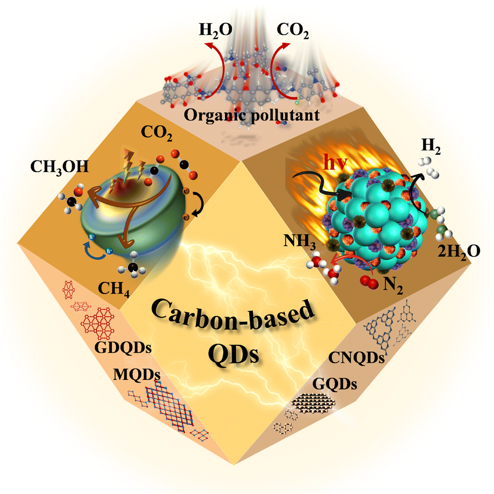
As excellent 0D materials, QDs are widely employed in nanosemiconductors due to their small particle sizes and large surface areas.1 The unique structure of QDs endows the material with a smaller Bohr radius, an obvious quantum size effect, excellent metal conductivity, and outstanding hydrophilicity.2–4 Thus, QD-based materials have attracted extensive attention from researchers in many fields.5 Early traditional QDs, such as CdSe QDs,6 PbSe QDs,7 Ag2S QDs,8 ZnSe QDs,9 are considered harmful to the environment due to their high toxicity and low biocompatibility, and thus, suffer from a difficult application bottleneck. Under the concerns of environment impact and public demand, there is an urgent need to develop green and non-toxic carbon-based QD materials.10 As a result, various carbon-based QDs, including GQDs, CNQDs, MQDs, GDQDs, have rapidly become a research hotspot (Fig. 1), due to their superior sustainability and good biocompatibility.11–13 With further research, a variety of synthesis strategies have been reported gradually, including the hydrothermal/solvothermal method, ultrasonic treatment, chemical etching and pyrolysis.14 However, different synthesis methods have their own advantages and disadvantages, resulting in the expected research interest in the properties and applications of carbon-based QDs.15–18 | ||
| Fig. 1 Synthesis strategies and structures of different carbon-based QDs. | ||
Carbon-based QDs, as a new material with broad application prospects in the fields of materials, energy and environment, have been widely verified. In fact, the number of studies on carbon-based quantum dots has exploded in recent years. Therefore, it is particularly important to rationally design highly active, selective and stable carbon-based QDs, and deeply explore their underlying physicochemical properties and photocatalytic mechanisms. Most importantly, different from previous reviews, which only focused on the application of QDs in photocatalysis, this work mainly focuses on the structural properties, synthesis strategies and photocatalytic promotion mechanism of emerging carbon-based QDs.
Photocatalysis is considered to be an effective means to solve the energy shortage due to the sustainability of solar energy. The most common photocatalysts are metal semiconductors, but some metals are harmful to the environment and human health, such as Pb, Co, etc. Accordingly, metal-free photocatalysts, such as GQDs, CNQDs, and GDQDs, have gradually come into the researcher's focus and have gained widespread attention. As a 0D conductive material, carbon-based QDs have excellent electrical conductivity and size effects. Moreover, their surface functional groups are highly adjustable, so they can be coupled with semiconductors to obtain suitable band positions, thereby enhancing the photocatalytic efficiency. Additionally, the excellent specific surface area and abundant surface functional groups of carbon-based QDs endow them with a strong adsorption capacity for reactants, which is conducive to the photocatalytic process. Furthermore, carbon-based QDs consist only of Earth-abundant C or N elements, making them easy to synthesize.19,20 As an important branch of carbon-based QD research, the study of MQDs for photocatalytic degradation and biosensing is also an important research hotspot that cannot be ignored due to the low toxicity of MQDs.21–24 Although significant achievements have been made in the research of carbon-based QDs, this attractive field has only just gained a foothold, and there are still many fundamental technological gaps and challenges to be filled.
Herein, papers related to carbon-based QDs published from 2000 to 2022 are selected to compare the structural and functionalization characteristics of carbon QDs, as well as the advantages and disadvantages of diverse preparation and modification methods through theoretical simulations. In addition, research progress for common applications of carbon-based QDs in photocatalysis is summarized systematically (Fig. 2). We hope that this work can guide new research directions for carbon-based QDs to meet the high requirements of diverse applications.
 | ||
| Fig. 2 Overview of the photocatalytic applications of carbon-based QDs. | ||
2. Structural properties of carbon-based QDs
Studying the structures of QDs has important implications for understanding their properties, as the structural characteristics could lead to predicting the properties of the materials to a certain extent.25,26 In addition to bonding and active sites on the surface, many groups on the surface of carbon-based QDs convey excellent biocompatibility and water solubility. Carbon-based QDs are also suitable for surface passivation and chemical modification of various polymeric, biological, organic, or inorganic materials. Through surface passivation, the physical and fluorescent properties of QDs are enhanced. Although bulk carbon-based materials have zero bandgaps, by cutting 1/2D carbon-based materials into 0D QDs, the bandgaps of carbon-based materials can be adjusted from 0 eV to that of benzene. Compared with 2D carbon-based nanosheets and 1D carbon-based nanobelts, 0D carbon-based QDs not only inherit the unique layer structures, excellent optical/electrical performance, and transport properties as well as exceptional thermal and chemical stability,27 they also exhibit stronger quantum confinement and edge effects when the particle size is reduced to 10 nm, thus resulting in new physical properties, which greatly expand their applications.28,29Carbon-based QDs are mostly single-layer or double-layer materials with particle sizes of only several nm and less than 1 nm thick.30 Graphene is a single layer of carbon atoms packed tightly together in a 2D honeycomb lattice, which can be packaged as 1D carbon nanotubes, 3D graphite or even divided into 0D GQDs.31,32 Although the largest published size is approximately equal to 60 nm, the transverse size of QDs is typically only several nanometers. As they are considered to be graphene with a reduced size, the exact structural formulation of GQDs is uncertain and usually represented by their structural characteristics, namely, the layer number and oxygen content, so the specific characteristics of GQDs in research are further described by size, defects, and acidity. GQDs are mostly oval or circular, but experts are devoted to the synthesis of square, hexagonal and triangular GQDs. Fig. 3a displays the orientation of a typical hexagonal graphene network, including the opposite zigzag and armchair directions. The edges of carbon-based QDs are mainly parallel to the zigzag orientation.33,34 CNQDs have two basic structural units of a triazine ring (C3N3) and a 3-s-triazine ring (C6N7) (Fig. 3b and c), and the latter is usually more stable than the former.35,36 When the two elemental units extend infinitely in the plane, a network structure named CNQDs is formed. CNQDs can be obtained from g-C3N4 nanosheets.37–40 Compared with g-C3N4, CNQDs with atomic thickness and a graphite-like lamellar structure, have a higher specific surface area, which is more favorable for a photoresponse and charge transfer.41,42 In addition, MQDs are a layered accordion-like carbon-based material (Fig. 3d).43,44 The general formula of MQDs is Mn+1XnTx (n = 1–3), where M stands for an early transition metal; X is carbon or nitrogen; T is a surface terminating group (halogen functional groups, chalcogen functional groups, imino and vacancy functional groups), which is obtained by etching of the A-layers from MAX (Fig. 3e).45–49 Since the MAX and MXene phases have hexagonal symmetry structures, the derived MQD systems form hexagonal lattices with the same symmetry.50–56 Zeng et al. established a hexagonal cluster MQD model for DFT calculations, in which the size of the model was on the brink of the experimental size; this proved the reliability of the calculation results.57 The high resolution TEM (HRTEM) images of GDQDs demonstrate a typical crystalline structure with a lattice spacing of 0.42 nm (Fig. 3f),58 which is considered to be similar to that of graphdiyne with a reduced size. GDQDs is constructed by inserting two ethynyl units (–C![[triple bond, length as m-dash]](https://www.rsc.org/images/entities/char_e002.gif) C–) between two neighboring aromatic rings as exhibited in Fig. 3g.59,60
C–) between two neighboring aromatic rings as exhibited in Fig. 3g.59,60
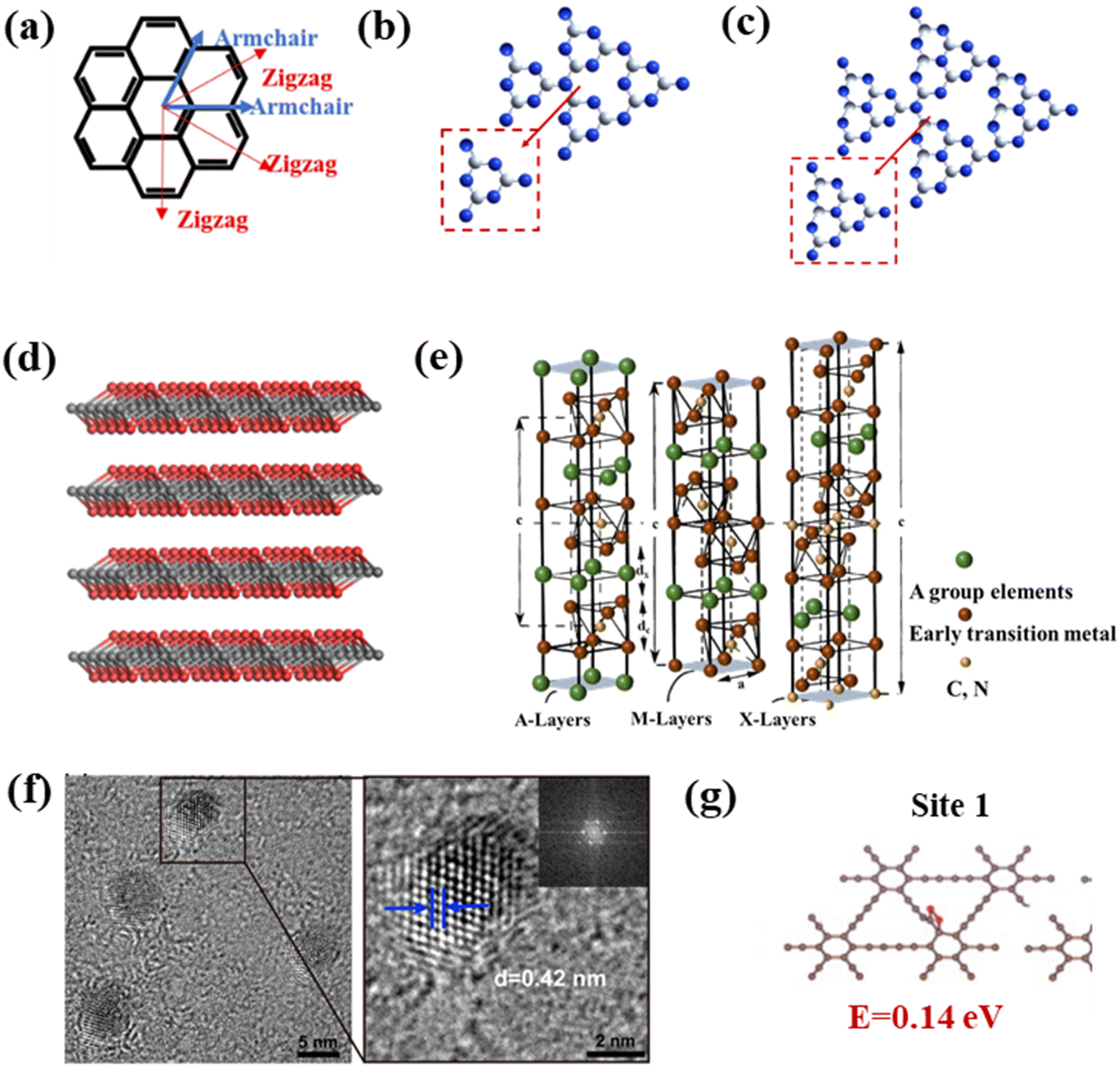 | ||
| Fig. 3 (a) Hexagonal structure of graphene, (b) structural model of C3N3, (c) C6N7 QDs, (d) layered accordion-like Ti3C2 QDs, (e) crystal structures of MAX phases, and (f) TEM (HRTEM) of GDQDs.58 Reprinted with permission. Copyright 2019, American Chemical Society. (g) Structural model of GDQDs.59 Reprinted with permission. Copyright with 2020 Elsevier. | ||
3. Synthesis strategies for carbon-based QDs
Over the past few years, the synthesis methods for carbon-based QDs have been widely developed. The most common synthesis methods are the hydrothermal/solvothermal method, ultrasonic treatment, high-temperature pyrolysis, and chemical etching. In addition, some special synthesis methods, such as electrochemical stripping, ball milling and micro-explosion, have also been studied consecutively. Different carbon-based QDs have a variety of precursors (Fig. 4), so they can exhibit different properties, such as hydrophilicity, biocompatibility, electron transport performance, etc.11–13,15–21,45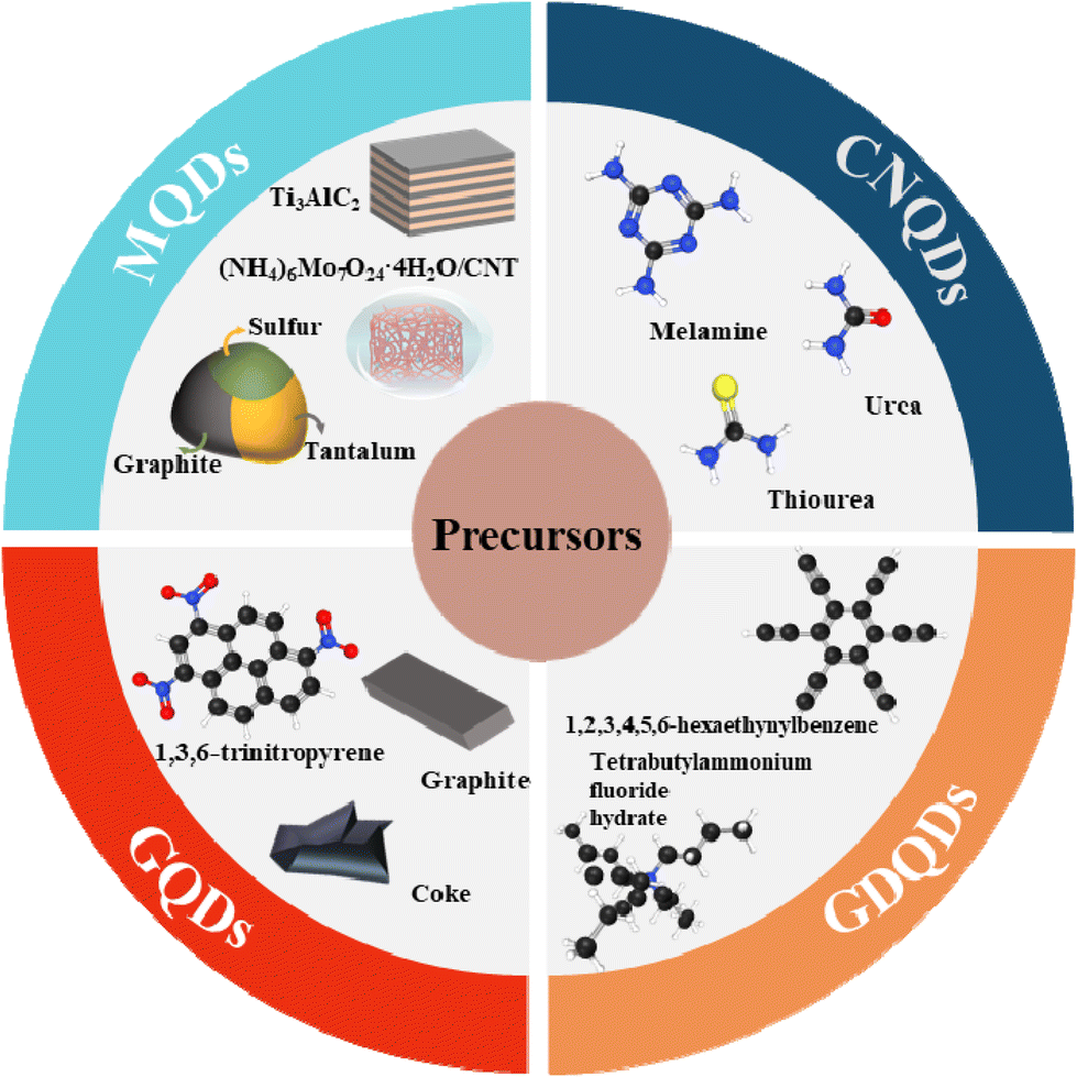 | ||
| Fig. 4 Different precursors of carbon-based QDs.12,15–21,45 | ||
Each experimental approach has its own merits and demerits, and the selected precursors also affect the characteristics of the obtained carbon-based QDs, such as size, dispersion, surface functionalization, etc. By optimizing the synthesis method, the size, morphology and structure of the as-prepared carbon-based QDs can be tuned to obtain satisfactory structures and properties.17,61
3.1. Hydrothermal/solvothermal method
The hydrothermal method is a top-down approach to catalyst synthesis based on heating and pressurizing the reaction system in a specially designed autoclave. An aqueous solution is used to create a relatively high temperature and pressure environment, in which precursors can be dissolved and recrystallized for inorganic synthesis. The hydrothermal/solvothermal method is the most common method to prepare carbon-based QDs15,17 due to its high specificity, simple operation, good selectivity, high accuracy, and good reproducibility. For example, boron-doped GQDs (B-GQDs) are synthesized by the one-step bottom-up molecular fusion of 1,3,6-thiotriazinone and borax in sodium hydroxide solution (Fig. 5a and b) under hydrothermal conditions. The obtained B-GQDs not only possess high crystallinity, uniform particle size, absolute luminescence yield and high selectivity to Fe3+, but also display excellent water dispersibility, outstanding biocompatibility, high photostability, as well as significant quantum confinement and edge effects.62 More importantly, the gram-level production of B-GQDs can be achieved by using the hydrothermal method, and the yield is even as high as 71%, showing great potential for practical applications. Similarly, CNQDs can also be obtained via high-temperature hydrothermal treatment of graphitic carbon nitride (g-C3N4) under strongly acidic conditions (Fig. 5c and d).63 However, this hydrothermal synthesis of CNQDs involves high temperature and a strong acid (H2SO4 and HNO3), which may not be in line with the concepts of green and sustainable development. Therefore, green preparation methods of CNQDs need to be developed urgently. MQDs, a new type of carbon-based QDs, were first synthesized by hydrothermal cutting of massive layered Ti3C2 in 2017. Moreover, the morphology and size of MQDs can also be controlled by changing the reaction temperature. Therein, MQD-120, as a multicolor cell imaging reagent, exhibits higher quantum yields than other materials, displaying surprising potential for the field of optics, which is of great significance for broadening the application field of MXenes.11 Recently, researchers successfully prepared MQD/g-C3N4 composite by the solvothermal treatment of Li-dissolved MXenes with g-C3N4 in dimethyl sulfoxide solution (Fig. 5e). Additional studies confirm that the introduction of MQDs can significantly increase the specific surface area of g-C3N4, thereby exposing a higher density of active sites (Fig. 5f), which is beneficial for the photocatalytic HER process.64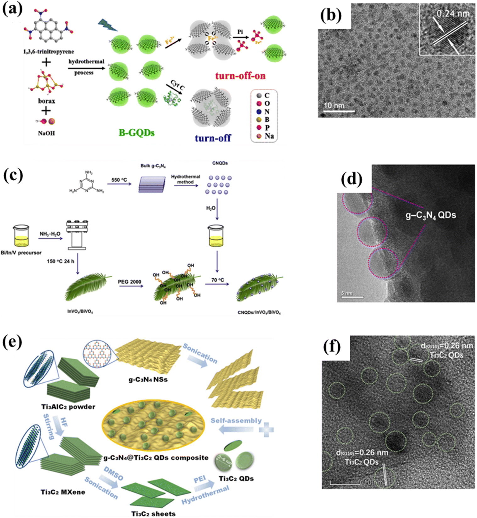 | ||
| Fig. 5 (a) Synthesis process for B-GQDs and (b) the corresponding TEM image.62 Reprinted with permission. Copyright 2019, Elsevier. (c) Preparation scheme for CNQD/InVO4/BiVO4 and (d) the corresponding HRTEM image.63 Reprinted with permission. Copyright 2016, Elsevier. (e) Preparation diagram of g-C3N4@Ti3C2 QDs and (f) the corresponding HRTEM image.64 Reprinted with permission. Copyright 2019, American Chemical Society. | ||
3.2. Chemical etching method
Chemical etching means the direct chemical interaction of a precursor with an external medium, causing damage to the surface structure or even inducing chemical reactions. It differs from electrochemical etching, in which an electric current is generated. Sapkota et al. reported a two-step liquid-phase chemical dissolution synthesis route for the large-scale production of GQDs. Typically, graphite is dispersed in water to form a dark brown dispersion, which is then cleaved with lysine to obtain a series of golden GQDs (Fig. 6a). Among them, GQDs with sizes ranging from 15 to 35 nm have excellent surface chemistry and fluorescence properties, which are manifested by strong visible fluorescence (average quantum yield of 0.64) and a high two-photon absorption (TPA) cross-section. Moreover, the size of GQDs before and after gelation are still uniform and regular as displayed in Fig. 6b. Additionally, the obtained GQDs also exhibit good cell permeability for live epithelial cells since they have a microscopic size, thus showing potential for bioimaging applications.65 The preparation of GQDs by chemical etching opens up the way to prepare other carbon-based QDs. Subsequent scholars have found that chemical etching is also suitable for the preparation of CNQDs and MQDs. For instance, CNQDs with sizes ranging from 5 to 9 nm could be obtained by acidic or hydrothermal cutting of g-C3N4 nanosheets (Fig. 6c and d).41,66 MQDs with an average grain size of 5 nm are successfully prepared by acid etching of Ti3AlC2 (Fig. 6e and f).67 Chemical etching is a popular preparation method for the assembly of carbon-based QDs because of its advantages of simplicity and economy.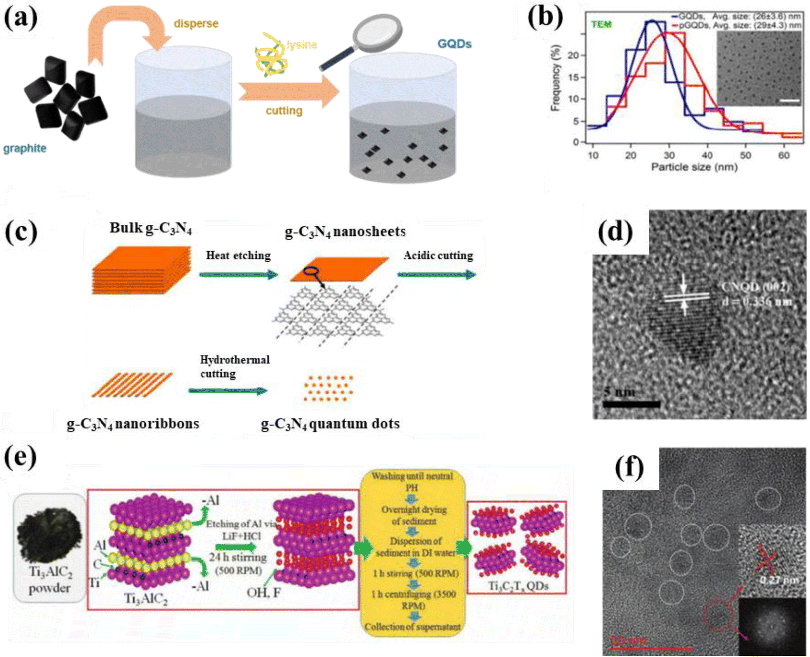 | ||
| Fig. 6 (a) Schematic illustration for the synthesis of GQDs and (b) particle size distribution of GQDs (inset is a TEM image of the GQDs).65 Reprinted with permission. Copyright 2017, American Chemical Society. (c) Synthesis process for CNQDs and (d) HRTEM image of CNQDs.41 Reprinted with permission. Copyright 2014, The Royal Society of Chemistry. (e) Preparation scheme for MQDs and (f) the corresponding TEM image. Reprinted with permission.67 Copyright 2020, Wiley-VCH Verlag GmbH & Co. KGaA, Weinheim. | ||
3.3. Ultrasonic method
Ultrasonic synthesis is a common top-down synthesis method. Ultrasound is a high frequency sound wave that causes mechanical forces to be transmitted through vibrations, thus changing the morphology of the material; this technique can be divided into probe ultrasound and water bath ultrasound. Compared with the outcomes of the water bath ultrasound method, the materials obtained by the probe ultrasound method are more dispersed and have a higher crushing strength, which requires a higher experimental operation level.4,68,69 Typically, uniform GQDs with a diameter of 3–5 nm can be prepared via a simple ultrasonic method using graphene as a precursor (Fig. 7a and b). The as-prepared GQDs exhibit excitation-independent down-conversion and up-conversion photoluminescence behaviors. In another example, the photocatalyst composed of rutile TiO2/GQDs and anatase TiO2/GQDs is produced by the ultrasonic method and displays an outstanding photocatalytic degradation rate of methylene blue, which can reach 9 times that of the anatase TiO2/GQDs.70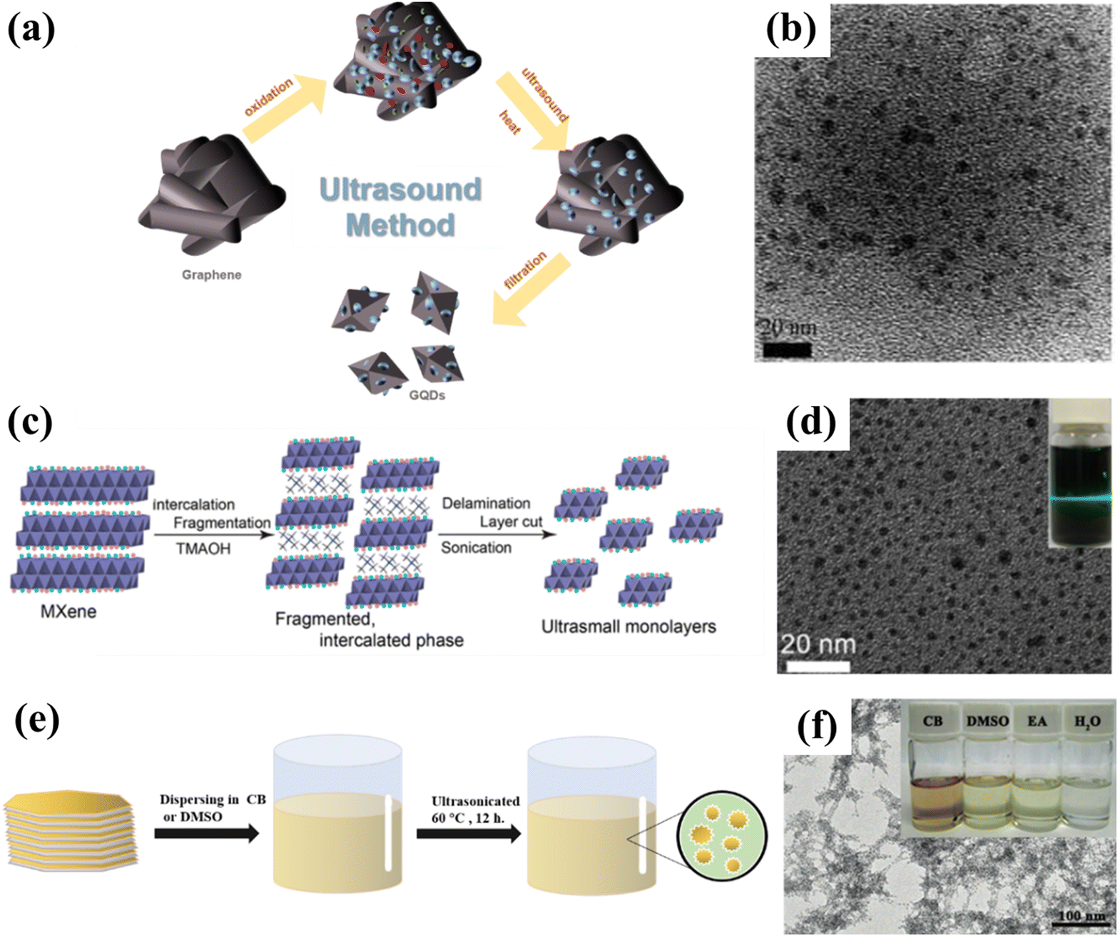 | ||
| Fig. 7 (a) Synthesis process for GQDs and (b) the corresponding TEM image.70 Reprinted with permission. Copyright 2012, American Chemical Society. (c) Preparation procedure for ultrasmall Ti3C2 sheets and (d) the corresponding TEM image.71 Reprinted with permission. Copyright 2017, American Chemical Society. (e) Schematic illustration of the synthesis of GDQDs and (f) the corresponding TEM image.59 Reprinted with permission. Copyright 2017, Wiley-VCH Verlag GmbH & Co. KGaA, Weinheim. | ||
Sonication is especially common in the preparation of MQDs. Wang et al. used TMAOH to break the Ti–Al bond in Ti3AlC2 by ultrasonic treatment for the first time. In this process, lamella cutting and separation can be performed simultaneously, thus successfully yielding ultra-small Ti3C2 QDs with exceptional optical properties (Fig. 7c and d). The obtained Ti3C2 QDs not only have very similar optical properties to those of carbon dots, but also exhibit excellent photoluminescence properties. It is encouraging to note that this method is also applicable to the preparation of other MQDs, such as Nb2C QDs and Ti2C QDs.71 Particularly, uniform-sized GDQDs with a diameter of 3–5 nm are prepared by ultrasonically dispersing graphdiyne powder in a mixture of chlorobenzene (CB), dimethyl sulfoxide (DMSO), ethanol (EA) and H2O (Fig. 7e and f). The obtained GDQDs can be employed as surface modifiers or dopants for perovskite solar cells, in which, GDQDs not only contribute to higher current density, filling factor, and open-circuit voltage, but also significantly improve the stability of the solar cell. Compared with the control sample, the power conversion efficiency of the modified device is improved by more than 15%, and it is expected to be widely used in the future.59
3.4. Pyrolysis method
In pyrolytic synthesis, two or more atoms or molecules are driven by high temperatures to recombine and restructure, resulting in the creation of entirely new substances. In contrast to top-down synthesis, this bottom-up method is a chemical reaction that transforms a material from being microscopic to potentially being macroscopic. Take the preparation of GQDs as an example, the pyrolysis method usually involves mixing samples and subsequent pyrolysis at high temperatures as shown in Fig. 8a. With the increased urea content, GQDs not only contain rich nitrogen dopants, but also form binary crystals. Moreover, the prepared GQDs possess a uniform particle size (Fig. 8b) and have a high quantum yield of 22.2%, showing potential application value in the fields of optics, sensing, energy, and biology.72 It is worth mentioning that GQDs are the first carbon-based QDs obtained by high temperature pyrolysis. Subsequently, the preparation of other carbon-based QDs via pyrolysis was demonstrated. As shown in Fig. 8c, CNQDs are prepared by the heat treatment of citric acid and thiourea. Moreover, the obtained CNQDs not only display a uniform particle size (Fig. 8d), but also exhibit strong blue light photoluminescence properties in terms of a quantum yield of 14.5%.73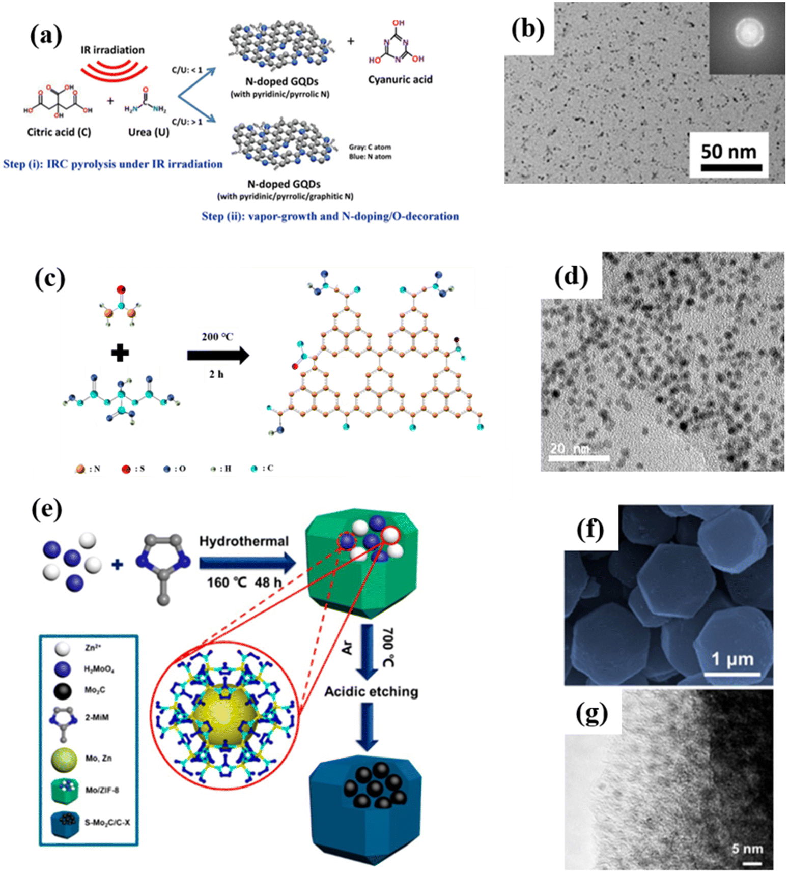 | ||
| Fig. 8 (a) Pyrolysis preparation process for NGQDs and (b) the corresponding HRTEM image.72 Reprinted with permission. Copyright 2019, Elsevier. (c) Formation mechanism of OS-GNCQDs and (d) the corresponding TEM image.73 Reprinted with permission. Copyright 2015, Royal Society of Chemistry. (e) Schematic diagram for the synthesis of Mo2C QD/C, and (f) the corresponding SEM and (g) TEM images.74 Reprinted with permission. Copyright 2018, American Chemical Society. | ||
Likewise, Wang et al. synthesized Mo2C QD/carbon polyhedron (Mo2C QD/C) composites by the pyrolysis method and subsequent acid etching using 2-methylimidazole as a precursor (Fig. 8e). The results show that the Mo2C QD/C composites not only inherit the polyhedral shape of the matrix, but also form uniformly distributed Mo2C QDs on the surface of the carbon matrix (Fig. 8f and g). The composites show the characteristics of good impedance matching, strong reflection loss (−60.4 dB) and wide bandwidth (14.5 GHz), thereby exhibiting a good microwave absorption effect in the range of 2.0–18.0 GHz, which is superior to most of the previously reported cemented carbide composites.74 However, there are currently only three kinds of carbon-based QDs reported that can be prepared by high-temperature pyrolysis. Therefore, the high-temperature pyrolysis method needs to be further studied to prepare a variety of carbon-based QDs.
3.5. Other methods
Although the above methods are usually effective and common for the preparation of carbon-based QDs, they still suffer from many disadvantages, such as being time-consuming, low yield, and poor repeatability. Hence, scholars in related fields have always been committed to searching for better synthesis methods, including electrochemical stripping, micro-explosion and ball milling. For instance, GQDs with a particle size of several nanometers can be prepared via the electrochemical stripping method (Fig. 9a and b) by employing coke, platinum and methanol solution as the working electrode, counter electrode and electrolyte, respectively.75 This method has numerous advantages, such as using a cheap and readily available coke feedstock, mild conditions, and high yield, which will make such preparation methods for coal-based GQDs more diverse and meaningful.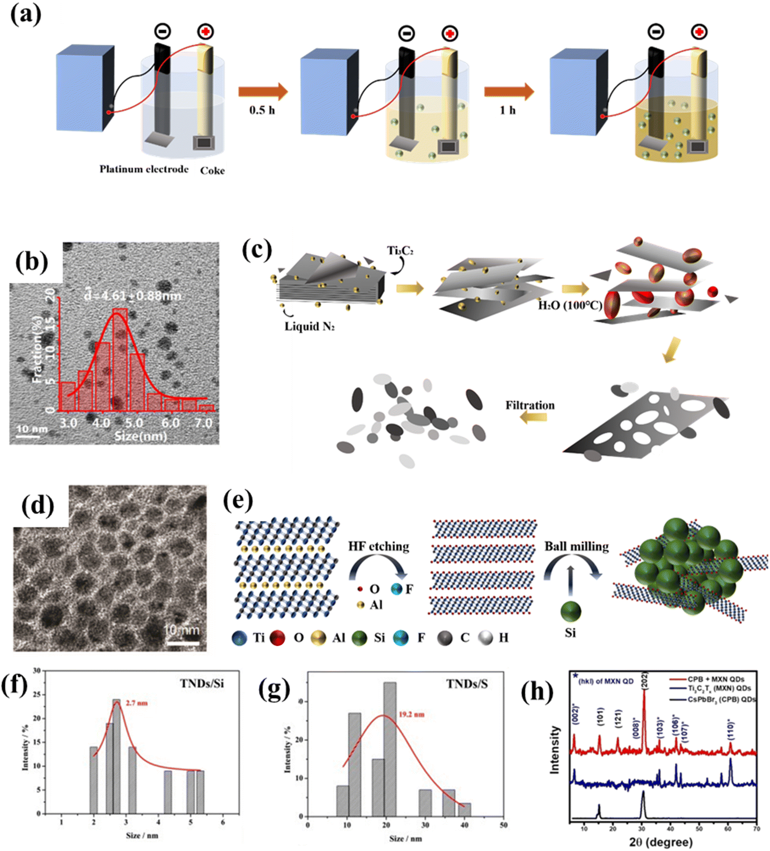 | ||
| Fig. 9 (a) Synthesis process for GQDs and (b) The TEM image of GQDs.75 Reprinted with permission. Copyright 2018, Elsevier. (c) Preparation procedure for NMQD–Ti3C2Tx and (d) the corresponding TEM image.76 Reprinted with permission. Copyright 2020, Wiley-VCH Verlag GmbH & Co. KGaA, Weinheim. (e) Schematic illustration of the ball milling of TNDs, (f) particle size distributions of TND/Si and (g) TND/P.77 Reprinted with permission. Copyright 2018, Wiley-VCH Verlag GmbH&Co. KGaA, Weinheim. (h) XRD patterns of MQD-based materials.78 Reprinted with permission. Copyright 2020, American Chemical Society. | ||
In addition, on the basis of general synthesis methods, scholars have developed some more economical and higher-yield synthesis methods. Li et al. prepared Ti3C2 QDs using a self-designed micro-explosion method in a closed space. In this process, the volume of N2 can be expanded nearly 700 times by temperature control, thus micro-explosion could have enough destructive power to form a porous structure. As exhibited in Fig. 9c and d, the microstructure of Ti3C2Tx was affected by micro-explosion, therefore, generating Ti3C2 QDs with strong biocompatibility.76 Although this method has particularly good effects of intercalation and fragmentation, we should also pay attention to the potential danger of using high-pressure gas in synthesis. Furthermore, ball milling is a universal synthesis method that uses high-energy shear forces to change the shape and size of substances to obtain the desired product. For example, Zhan et al. prepared various modified Ti3C2 QDs by ball milling layered Ti3C2Tx with solid elements (P, Si, C and S, Fig. 9e). Among them, Ti3C2 QD/P possesses the best battery performance (Fig. 9f and g).77 Inspired by this research, Pandey et al. first ball-milled Ti3AlC2 into nano-sized particles, and then etched away Al species to obtain Ti3C2 QDs (Fig. 9h). Compared with the previous methods, ball milling is more suitable for the large-scale production of QDs.78
In general, compared with conventional methods for preparing carbon-based QDs, electrochemical stripping, micro-explosion and ball milling have many advantages, including being non-toxic, convenient operation, low cost, and suitability for large-scale preparation. But electrochemical stripping has not been widely applied in the research community, and the micro-explosion method is still dangerous due to the need for high-pressure gas to participate in the reaction. Additionally, the above methods have not been vigorously promoted due to insufficient related research. It is expected that these methods will be further explored in the future. According to different synthesis methods, the advantages and disadvantages of various synthesis approaches to carbon-based QDs are summarized in Table 1.
| Method | Materials | Advantages | Disadvantages |
|---|---|---|---|
| Hydrothermal/solvothermal | GQDs, CNQDs, MQDs, GDQDs | High specificity, simple operation, good selectivity, high accuracy, excellent reproducibility, non-toxic, size controllability.79 | Long reaction time, low production yield, harsh reaction conditions and experimental requirements.79 |
| Chemical etching | GQDs, CNQDs, MQDs | Simple and cost-effective.67 | Poor tunability of morphology,80 low efficiency and uncontrollable product.81 |
| Ultrasonic | GQDs, MQDs, GDQDs | Effective and safe.53 | High equipment demand,80 time consuming, low output and difficult repeatability.53 |
| Pyrolysis | GQDs, CNQDs, MQDs | Controllable performance,80 high atomic efficiency, adjustable microstructure,53 easily achievable, and inexpensive.81 | Demand for high temperature heat treatment, emission of polluting gases.81 |
| Electrochemical stripping | GQDs | Abundant surface functional groups.81 | Vulnerable aromatic carbon structures,81 and uncontrollable microstructures. |
| Ball milling | MQDs | High productivity.53 | Uncontrollable particle size and morphology, time-consuming. |
| Micro-explosion | MQDs | Non-toxic, convenient operation, low cost, suitable for large-scale preparation.76 | High gas pressure demand, low safety factor.76 |
4. Modified strategy
Although carbon-based QDs are favored in the field of photocatalysis, there are still some limitations of the primordial carbon-based QDs. To compensate for the shortcomings of the original carbon-based QDs, they can be modified in various ways: composition modification, structure modification and heterojunction modification. Primitive carbon-based QD catalysts are often limited by factors such as the range of light absorption or the compounding of photogenerated carriers due to their own structural or performance defects, which hinders them from performing optimally as catalysts. During research on photocatalysis, scholars have therefore been working on two central questions: broadening the absorption range of light and improving the separation efficiency of carriers to widen the bandgap and increase the adsorption of small gas molecules.4.1. Composition modification
Changes to the elemental composition is usually a relatively efficient and low-cost modification. Metal doping and non-metal doping have been developed to modify the composition of carbon-based QDs. In order to simultaneously modify the crystal, weave and electronic structure, the material is improved by enhancing light absorption, promoting charge separation and transport, and extending the charge carrier lifetime. Modification of the elemental composition is particularly common in the modification of carbon-based QDs, with the use of N as the most common dopant, along with S and Cl, which are also favored (Fig. 10a). Doping with non-metal elements primarily improves the light absorption range of the catalyst, which influences the photocatalytic function of the catalyst. It is mostly accomplished by narrowing the semiconductor's bandgap. In most cases, doping with non-metals primarily reduces the band gap by raising the edge of the valence band rather than creating the donor energy level.82 The doped metal may induce flaws or alter the crystallinity of the original semiconductor, which will affect the recombination of photogenerated electrons and holes. For instance, the lifetime of carriers can be prolonged when the doped metal acts as a potential well for electrons or holes, whereas the recombination of carriers is accelerated when the doped metal is positioned in the electrons or holes’ rebuilt center. In other words, doping with a metal can have both good and bad effects on photocatalysis. This mostly depends on the type, quantity, and manner of dopant metal elements and catalysts.82,83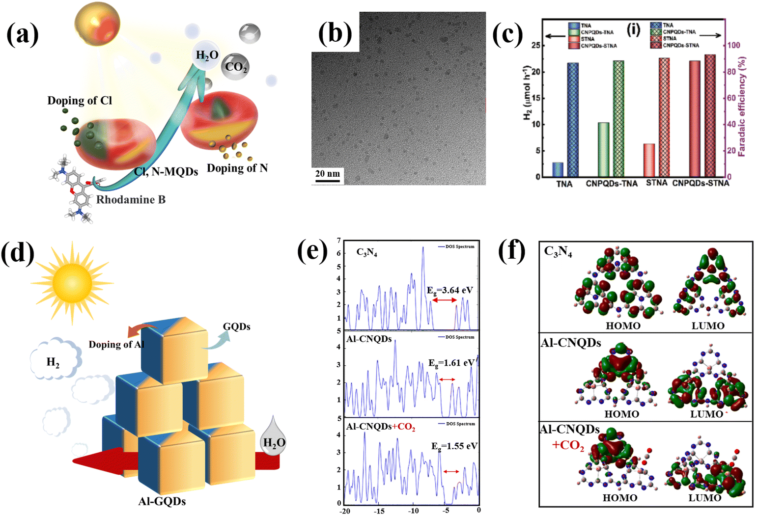 | ||
| Fig. 10 (a) Schematic illustration of non-metal doped carbon-based QDs and (b) TEM of S,N-GQDs.84 Reprinted with permission. Copyright 2015, Wiley-VCH Verlag GmbH & Co. KGaA, Weinheim. (c) H2 production rate of P-GDQDs.88 Reprinted with permission. Copyright 2019, WILEY-VCH Verlag GmbH & Co. KGaA, Weinheim. (d) Schematic illustration of metal doped carbon-based QDs, (e) DOS diagrams for the energy surfaces of the molecular orbitals of g-C3N4, Al-C3N4 QDs and Al-doped C3N4 QDs in the presence of CO2, and (f) calculated spatial distribution of the HOMOs and LUMOs of g-C3N4, Al-C3N4 QDs and Al-doped C3N4 QDs in the presence of CO2.90 Reprinted with permission. Copyright 2022, Elsevier. | ||
As the earliest carbon-based QDs, GQDs are also suitable for modification by non-metal doping. Qu prepared S,N Co-GQDs (Fig. 10b); S and N doping may change the chemical composition of GQDs, so three independent luminescence centers are proposed to coexist in S,N-GQDs. Doping GQDs with S, N provides an attractive way to effectively tune their optical properties and develop photocatalytic applications.84 Huang et al. doped GQDs with S element by hydrothermal methods (S-GQDs), the products had good crystallinity and mono-dispersity. S-GQDs exhibit excellent photocatalytic performance in the degradation of pollutants through visible light irradiation.85 In other research, N and Cl were implanted into the C skeleton and Ti boundaries by electrochemical processes during etching, the Cl,N-Ti3C2 MQD was directly stripped from bulk Ti3AlC2. The Cl,N-Ti3C2 MQD has a particle size of about 3.45 nm. In comparison with previously reported graphene-based nanoparticles, Cl,N-Ti3C2 MQDs exhibit a lower p-hydroxyl radical consumption rate (12.5 g mL−1) and a higher surface area to volume ratio.86 Similar to N-MQDs, doping with N can also improve the optical and electrochemical properties of GDQDs. In addition, the fluorescence performance is dramatically enhanced by the addition of N, and the number of surface defects of N-GDQD are increased by the addition of N element, which also significantly raises the quantum yield (from 14.6% to 48.6%). Additionally, due to the increased electrical conductivity brought about by doping with N, N-GDQDs experienced strong electron transfer and good electrical conductivity, which made it easier for electron transfer from N-GDQDs.87 Besides N-GDQDs, Kumar demonstrated that metal-free P-doped g-C3N4 QDs (P-CNQDs)/TiO2 photocatalysts could be used as effective catalysts for the H2 production. P-CNQDs/TiO2 structures enhance charge separation and electron transfer, resulting in significantly improved photocatalytic efficiency (Fig. 10c).88 Through the non-metal doping of various carbon-based QDs, we find that non-metal doping plays a major role in the modification of carbon-based QDs by enhancing the carrier separation efficiency to improve the photocatalytic conversion activity. The P and N elements are usually the first choice for the modification of carbon-based QDs due to their easy doping and good effects.
Montejo-Alvaro discovered that the binding energy of gas molecules to GQDs could be controlled if GQDs were doped with metal, as the addition of a suitable metal, such as Ni and Al, to graphene could improve its conductivity by reducing its band gap. The ELF contour demonstrates that Al-doped GQDs have a greater ability to adsorb NH3 than N-GQDs. Covalent connection of the C–Al bond of GQD means that water molecules interact with Al-doped GQDs via the lone pair of water in this location.89 The strong adsorption of small gas molecules to Al-GQDs can be used to lower the gas detection limits, and also be used for photocatalytic pollutant degradation in the future (Fig. 10d). Moreover, Abbass investigated the possibility of simulating natural photosynthesis and the sensing and adsorption applications of Al-g-C3N4 QDs. The doping of Al leads to a narrowing of the CNQD band gap and enhanced light absorption (Fig. 10e). Due to the narrow band gap and relatively high absorption, Al-g-C3N4 QDs can be introduced into the production of CH4 from CO2 and clean fuels from water-cracking processes (Fig. 10f).90 Tang prepared a catalyst with tunable Co doping; the prepared Co-MQDs had efficient light harvesting and charge separation/injection properties for use as photoelectrochemical water oxidation photoanodes. The introduction of Co triggered an accompanying surface plasma effect and acted as a water oxidation center, leading to visible light harvesting capability and improved surface reaction kinetics.91 In general, doping with metal elements facilitates the adsorption of reactants that exhibit different electronegativity from that of the pure carbon structure, which can alter their electroneutrality and thus induce charge transfer to form active sites.92
4.2. Structural modification
In order to remedy some inevitable drawbacks of carbon-based QDs, such as the tendency to be oxidized or agglomerate, functionalization is a way to improve their practical applications, and surface modification is the most common way to functionalize carbon-based QDs. The differences in the type and location of surface groups will seriously affect the properties of QDs.51,93–99 Based on the previous mechanistic analysis, different carbon-based QDs have certain functional differences. In order to highlight the outstanding performance of carbon-based QDs and apply their properties in photocatalysis, some specially designed carbon-based QDs are often prepared. For example, the abundant –F, –Cl, –NH, –OH, and –O groups on the surface of MQDs enhance the electronic conductivity of the material (Fig. 11a), and the Gibbs free energy (ΔGH*) of the adsorbed hydrogen atoms of –O-terminal T2C MQDs is close to 0 eV, indicating that they have great potential for photocatalytic hydrogen production.44,46,48,49,56 When terminated with –OH and –F groups, the band structure exhibits a semi-conductive property with a clear separation between the valence and conduction bands. Cl-terminated MQDs can be used as multifunctional synthons and be converted into MQDs with different surface terminal groups with the help of molten Lewis acid/basic salts.46 In addition to common groups, the presence of some vacancies would also enhance the properties of MQDs. When MQDs are applied to photocatalytic N2 reduction, the defect sites in the oxygen vacancy (OV) defect state are conducive to capture. And the activation of N2 molecules results in the efficient reduction of preactivated N2 molecules to NH3 (Fig. 11b).96 Bare MQDs are mostly conductors and can be used as cocatalysts to promote charge transfer.97 Different from MQDs, CNQDs often play a more prominent role as the main catalyst. Various defects on the surface of CNQDs lead to the formation of various functional groups. CNQDs with surface defects and electron-rich properties also exhibit unique nucleophilic properties from basic surface functional groups or H-bond motifs, thus facilitating their more valuable applications in the field of photocatalysis. The abundance of basic groups (–NH–, N–, and –NH2) on the surface of typical CNQDs facilitates photocatalytic CO2 reduction (Fig. 11c). In addition, CNQDs can also be used for photocatalytic pollutant degradation because most of the basic groups has the ability to adsorb acidic substances.98 After O was incorporated within CNQDs, the oxygen element mainly existed in the form of –COOH functional groups. These functional groups improved the response of CNQDs to visible light, as well as the separation of more obvious photogenerated charge carriers, thereby promoting photocatalytic RhB degradation (Fig. 11d).100 Compared with other carbon-based materials, GDQDs have a uniform distribution of pores, flexible electronic characteristics and lower atomic density, so that they can be used as a carrier transport channel in carbon-based catalysts to inhibit carrier recombination.60 GQDs are commonly optimized by two strategies to make them suitable for photocatalysis. The modification strategy focuses on emphasizing the electron donating ability of GQDs.101 At this time, the electron-donating parts, such as carboxyl functional groups, are connected to the electron-withdrawing part to couple the redox reaction and promote the separation of photogenerated electron–hole pairs (Fig. 11e).102 In addition, highly oxidized N-GQDs also contribute to the generation of H2 during photocatalysis because of the modification with –NH2 (Fig. 11f).95,103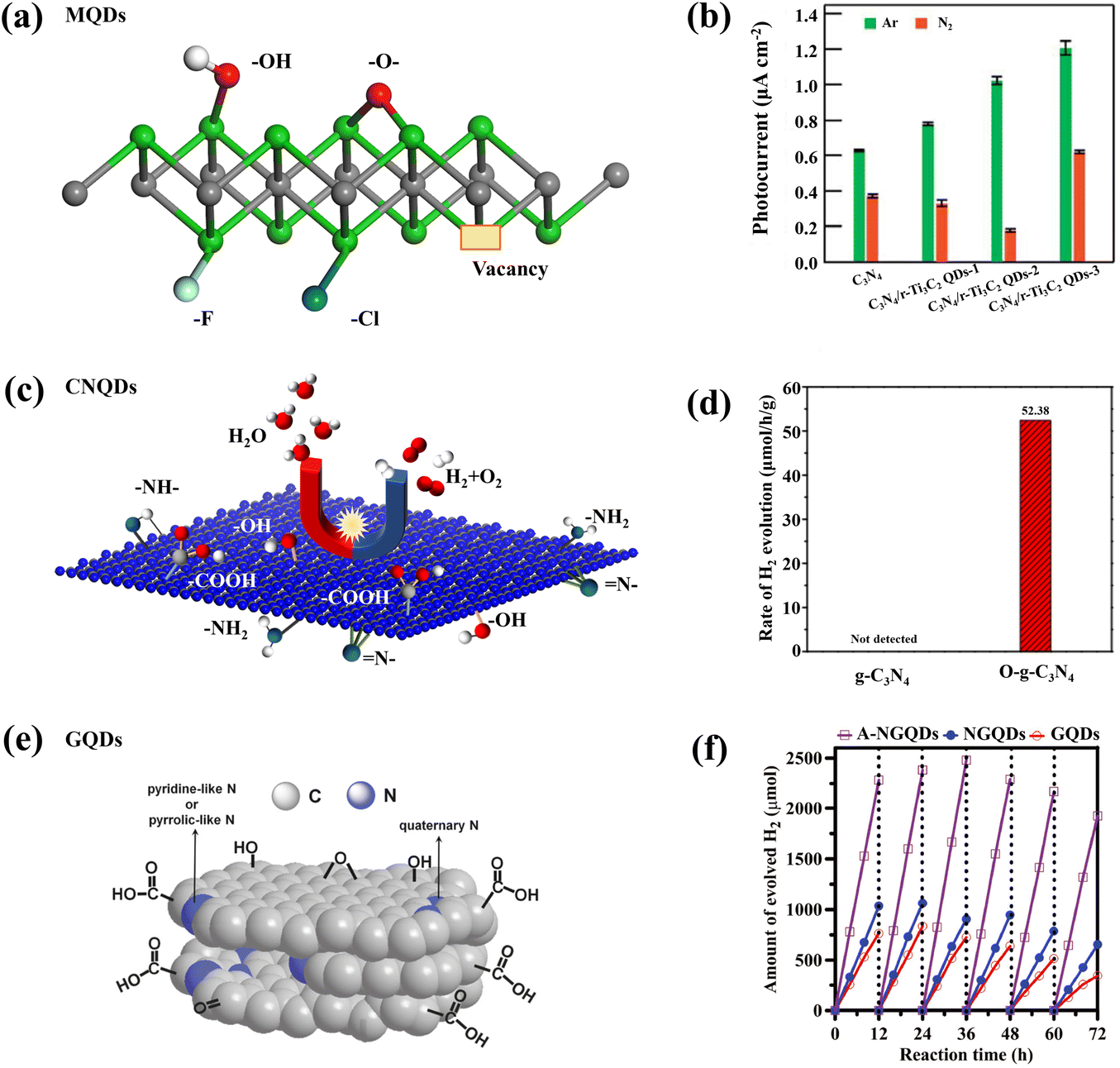 | ||
| Fig. 11 (a) Functional groups on the surface of MQDs.46 Reprinted with permission. Copyright with 2022, the Royal Society of Chemistry. (b) Photocatalytic hydrogen evolution rates of MQD-based catalysts.96 Reprinted with permission. Copyright 2022, Wiley-VCH Verlag GmbH&Co. KGaA, Weinheim. (c) Schematic representation of the functional groups of CNQDs and (d) photocatalytic hydrogen evolution rates of O-CNQDs.100 Reprinted with permission. Copyright 2015, American Association for the Advancement of Science. (e) Schematic representation of the functional groups of GQDs.102 Reprinted with permission. Copyright with 2014, Wiley-VCH Verlag GmbH & Co. KGaA, Weinheim. (f) Amount of evolved H2 with different GQDs.103 Reprinted with permission. Copyright 2020, Wiley-VCH Verlag GmbH&Co. KGaA, Weinheim. | ||
4.3. Heterojunction modification
Heterojunctions in binary or multiple semiconductors are also an effective way to increase the efficiency of photocatalytic reactions with carbon-based QDs, which often play the role of co-catalysts in the formation of composites. The heterojunction of semiconductors with different energy levels changes the carrier transfer path, facilitating charge transfer and the generation of holes from the photoexcitation process. When carbon-based QDs form heterojunctions, a carrier concentration gradient is created on the surface of the composite, which leads to the diffusion of carriers spontaneously. As a result, a layer of electrons accumulates and forms on one semiconductor, while a depletion layer forms on the other side, which facilitates the separation of photogenerated electrons and holes. With the separation of photogenerated electron–hole pairs, the heterojunction between these different semiconductors increases the catalytic activity.104 In addition to promoting carrier separation, carbon-based QDs form a heterojunction by bonding with other materials and can effectively extend their range of absorption of sunlight, thus facilitating photocatalysis.64For instance, Zhou prepared CNQDs that grew on the surface of g-C3N4. The enhanced photocatalytic performance of CNQD/CN can be attributed to effective charge separation and transfer at the interface between g-C3N4 and CNQDs, thanks to the excellent photoelectrochemical properties as well as the extended charge carrier lifetime. The self-modification strategy provides a rational and interesting design idea for the preparation of efficient photocatalysts.105,106 In addition to facilitating surface reactions, carbon-based QDs can also play a role in enhancing the absorption of light in heterojunctions. Liu successfully prepared the heterojunction structure of CNQDs attached to C3N4, and the presence of CNQDs enhanced the specific surface area and expanded the light absorption range of C3N4. In CNQD/C3N4, the quantum size effect of C3N4 QDs is a key factor in the construction of the heterojunction. This unique structure provides good intergranular compatibility.107 Carbon-based QDs not only promote light absorption, but also act as photosensitizers to generate electrons. A heterojunction photocatalyst (g-C3N4/MXene QDs) was prepared by hydrothermal treatment (Fig. 12a). Electron movement on the two surfaces effectively promoted the photocatalytic reaction.64 Liu prepared a Z-type NH2-MIL-125(Ti)/Ti3C2 MXene quantum dot/ZnIn2S4 (Ti MOF/QD/ZIS) photocatalyst, which was stable in both antibiotic photodegradation and hydrogen production experiments (Fig. 12b). This work identified a novel Z-type photocatalyst system for water purification and solar hydrogen production. As electron transfer mediators, MQDs play a decisive role in the photocatalytic activity of Z-type catalysts.108 GQDs are also commonly used in heterojunction modification strategies to make them suitable for photocatalysis. The heterojunction of GQDs emphasizes the electron transfer ability of GQDs, such as the coexistence of GQDs with p–n heterojunctions constructed from other materials to promote electron transfer (Fig. 12c), thereby enhancing the photocatalytic activity.95,102 The performance of GQDs with p–n heterojunctions was compared with that of ordinary GQDs, and the hydrogen production rate of the former was about twice that of the latter (Fig. 12d and e).102 It is evident from previous research that due to heterojunction modification, carbon-based QDs play a key role in all three steps of photocatalysis: light absorption, charge separation and surface reaction.
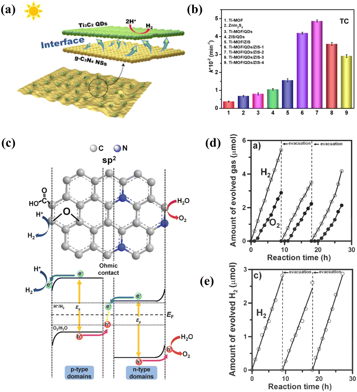 | ||
| Fig. 12 (a) Mechanism of heterojunction.64 Reprinted with permission. Copyright 2019, American Chemical Society. (b) Comparison of photocatalytic H2 evolution activity of different photocatalysts.108 Reprinted with permission. Copyright 2022, Elsevier. (c) Interaction of p-type and n-type semiconductors on the surface of GQDs and (d) evolution of H2 with NGO-QDs and (e) GO-QDs.102 Reprinted with permission. Copyright with 2014, Wiley-VCH Verlag GmbH & Co. KGaA, Weinheim. | ||
Table 2 is used to summarize the functionalization characteristics of carbon-based QDs. Although there is limited research on carbon-based QDs, functionalization is the key to realizing their practical applications, and further research is needed on more effective functionalization methods to improve the performance of carbon-based QDs.
| Carbon-based QD | Surface functional groups | Advantages | Disadvantages |
|---|---|---|---|
| GQDs | –COOH, –OH, –NH | Water soluble,33 the ability to give electrons is outstanding.102 | GQDs with hydroxyl showed high cytotoxicity (100 μg mL−1).101 |
| CNQDs | –COOH, –OH, –NH–, ![[double bond, length as m-dash]](https://www.rsc.org/images/entities/char_e001.gif) N–, –NH2 N–, –NH2 |
Main catalyst,98 hydrophilic,59 large number of surface defects.34 | Delocalized π bonds hybridize weakly with π bonds in sp2 leading to poor stability.109 |
| MQDs | –F, –O–, –OH, –Cl, –NH | Hydrophilic,48,49 strong electron transport capacity,97 strong adsorption of hydrogen atoms [photocatalysis technology is a green and sustainable energy conversion process, which exhibits great application potential in solving environmental pollution and energy shortage issues], biocompatibility.110,111 | Disabled as the main catalyst.97 |
| GDQDs | –COOH, –NH2 | Strong stability,58 uniform distribution of pores, flexible electronic characteristics and smaller atomic density,47 hydrophobicity.112 | Band gap is too narrow, the photogenerated charge carriers are easy to compound.113 |
5. Mechanism analysis
5.1. Theoretical simulations
In order to confirm the excellent performance and photocatalytic potential of carbon-based QDs, theoretical analysis is essential.57,114,115 Triazine (tg-CN) clusters are doped with p-block (B, O, S and P) elements and the CNQDs obtained by different doping methods are further compared using DFT. The calculations predict that B doping of both types of CNQDs favors the substitution of carbon atoms, while O, S and P doping favors the substitution of nitrogen atoms. The initial HOMO–LUMO gap and overall hardness of the CNQDs are reduced after doping, with the most significant changes to the hg-CN and tg-CN structures after O and S doping. hg-CN and tg-CN both became better electrophiles after modification, in particular, B-doped modified CNQDs exhibited the best performance (Fig. 13a).116 The energy gap of N-MQDs widens and combines gap states in the sub-gaps, compared to the original energy gap of MQDs and sub-gaps (0.15 eV) (Fig. 13b). Chemical bonding between Ti and N in Ti3C2 demonstrates how N-MQDs favor a decrease in charge and energy loss. The experimental results reveal an increase in lifespan from 5.89 ns to 7.06 ns, indicating that the existence of large gap states in MQDs boosts the carrier lifetime and enhances the quantum yield. Comparing MQDs and N-MQDs demonstrates that the energy gap widens as a result of nitrogen doping, extending the carrier lifetime and enhancing the quantum yield.117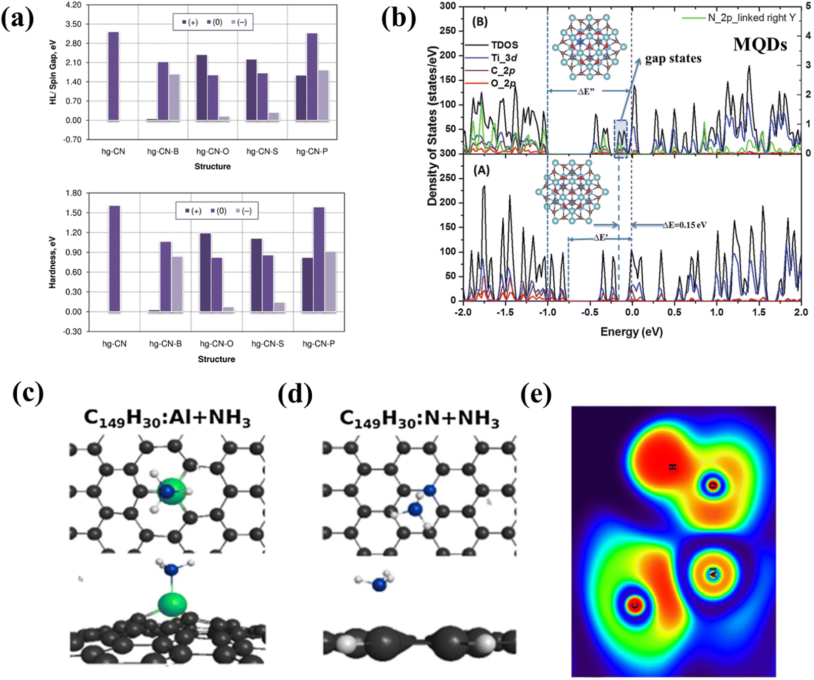 | ||
| Fig. 13 (a) HOMO–LUMO (HL) and global hardness of doped QD nanoclusters of pristine heptazine (upper panel) carbon nitride at the HSE06/6-311+G* level of theory.116 Reprinted with permission. Copyright 2018, Elsevier. (b) DFT calculated total and projected density of states of Ti3C2O2 QDs and Ti3C2−xNxO2 QDs. Reprinted with permission.117 Top and side views of the optimized geometries for the adsorption of NH3 on (c) N-GQDs and (d) Al-GQDs. (e) ELF contour maps for the adsorption of water on Al-GQDs.89 Reprinted with permission. Copyright 2019, Springer. | ||
In addition to the preparation process and structure, theoretical simulations can also predict the photocatalytic performance of carbon-based QDs, providing design guidance for high performance applications.86,96,118,119 The adsorption effects of Al-GQDs and N-GQDs prove the strong adsorption capacity of the catalysts for small gas molecules and H2O, which means that GQDs play an important role in photocatalysis according to DFT theory (Fig. 13c–e).89 In the GQD/g-C3N4 photocatalytic reaction mechanism, Bader charge calculations confirm that under light irradiation, photogenerated electrons excited by GQDs are transferred to g-C3N4 in a direction opposite to the internal electric field.114 In the photocatalytic hydrogen production process of ZIS-MQDs, a Schottky junction is formed at the ZIS–MQD interface and photogenerated electrons are transferred from the CB of ZIS to the surface of MQDs. The Ef of MQDs is close to that of Pt and is more positive than the CB of ZIS, and the Schottky barrier effectively prevents electron reflux, which confirms that ZIS-MQDs are suitable for photocatalytic HER.119 The H2O splitting energy of MQDs and MQD/Cu2O/Cu foam varies close to zero; the presence of MQDs increases the hydrogen binding energy and leads to excellent reaction kinetics.99
5.2. In situ analysis
In situ analysis of carbon-based QDs can purposefully confirm their structures or properties. For example, controlled binding morphology and in situ Raman analysis confirmed that dispersed GQDs not only provide sites to combine with other materials, but also regulate the electric field and ion flux to promote dendritic-free surface growth.120 In addition, in order to further study the color pressing effect of carbon-based QDs, the in situ high-pressure detection of MQDs was performed (Fig. 14a). With the increase in pressure, the fluorescence emission of MQDs showed a redshift, but MQDs still showed white luminescence (Fig. 14b). When the pressure increased to 5.0 GPa, the Raman spectra almost did not change, as proved by irreversible absorption spectra.121In situ PL detection of GQDs shows that the PL intensity increases during the reduction of GQD due to the migration of excitons from the sp3 defect state to sp2. The PL blueshift is due to the larger size transitions of π → π*. This confirms the dependence of GQD luminescence on the reduction/oxidation state.122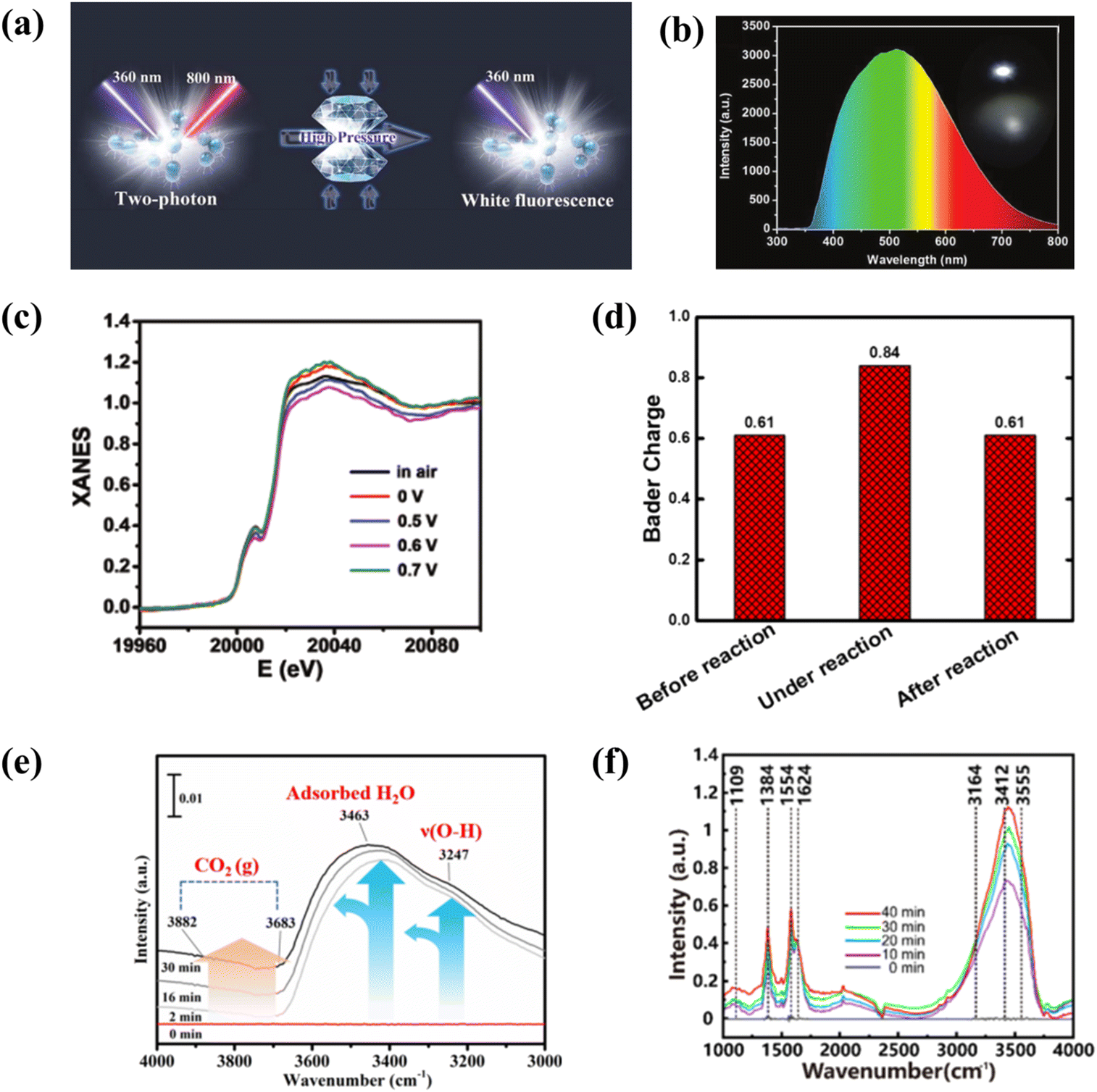 | ||
| Fig. 14 (a) Illustration of the properties of MQDs at high pressure in situ, and (b) photograph (insert) and emission spectrum.121 Reprinted with permission. Copyright with 2019 Wiley-VCH Verlag GmbH & Co. KGaA, Weinheim. (c) The calculated Bader charges for Mo atom and (d) XANES spectra of MoC QD/NS.123 Reprinted with permission. Copyright with 2018 Wiley-VCH Verlag GmbH & Co. KGaA, Weinheim. (e) In situ DRIFTS over BB@10CN catalyst.124 Reprinted with permission. Copyright 2022, Elsevier. (f) In situ FTIR spectra from the as-prepared 9MX-MOF nanosheet.125 Reprinted with permission. Copyright 2020, American Chemical Society. | ||
With different potentials, the edge energies of absorption are different (Fig. 14c). Compared with the PL intensity of GQDs in the reduction state, the PL intensity of carbon-based QDs in the high oxidation state may have a more prominent catalytic performance. MoC QD/NG are used for quinone catalysis, and electron transfer of the Bader charge of MoC QDs on the active site of the catalyst during the reaction could be further analyzed through the valence in situ EXAF analysis of Mo (Fig. 14d). With the assistance of the electric field, hydroquinone sulfonate (SHQ) is absorbed on the surface of MoC QD/NG. At the same time, MoC QDs are used as the catalytic site of the reaction, and the valence state changes.123 In addition to the identification of reaction sites, in situ analysis of carbon-based QDs helps us to understand their major roles in photocatalytic reaction progression. In order to accurately reduce the intermediates of CO2 photocatalysis and identify the intermediate pathways, in situ DRIFTS analysis is performed on the catalysts. As the excitation time increases, CO2 from all activated species accumulates on the BB@10CN catalyst, while it can be seen that b-CO32−, HCO3−, and ˙CO2− species are light sensitive and their adsorption intensities are affected by light-induced charge transport. This indicates that visible light successfully achieves an efficient separation of electron–hole pairs, and fast carrier transfer from the inside of the catalyst to the surface creates an opportunity for deep activation and conversion of the reactant (CO2) (Fig. 14e).124 In order to comprehend the effect of N-related functional groups, in situ FTIR is explored. During the coexistence of N2 and H2O, the absorption signal increased gradually from 0 to 30 min. Bands at 3555 cm−1 and 3164 cm−1 were attributed to N–H stretching. The 3412 cm−1 and 1354 cm−1 bands are from NH3, and 1109 cm−1 from adsorbed N2 (Fig. 14f). The strong N2 adsorption energy of MXene quantum dot/Ni-MOF was confirmed, which explained the reaction process of N2 photocatalytic reduction by MQDs from a mechanistic point of view.125
6. Photocatalytic applications
Photocatalysis is a green and sustainable energy conversion process, which exhibits great application potential in solving environmental pollution and energy shortages.41,61,70 Compared with 2D materials or 1D materials, 0D carbon-based QDs possess superior optical properties due to their stronger quantum confinement and boundary effects. Accordingly, carbon-based QDs are considered as promising photocatalysts for CO2 reduction, pollutant degradation, hydrogen (H2) evolution, and nitrogen reduction.536.1. Photocatalytic carbon dioxide reduction
Recently, the reduction of carbon dioxide (CO2) to energy fuels via photocatalytic technology is a promising approach to alleviate the energy crisis and global warming. The photocatalytic reduction of CO2 mainly relies on semiconductor-based photocatalysts. Raziq reported a CdSe QD modified phosphorus-doped g-C3N4 (P-CN) as a CO2 reduction photocatalyst. After P-doping and structural coupling with CdSe, QDs can significantly extend the optical response of g-C3N4 from visible light to the near-infrared boundary (700 nm). Thus, the yield of 4CdSe/P-CN from CO2 to CH4 is 47 μmol h−1 g−1 under visible light irradiation (Fig. 15a). A series of photochemical tests show that the introduction of 4CdSe/P-CN greatly promotes the separation efficiency of photosensitive carriers, which is the fundamental reason for the narrower bandgap and greater photocatalytic activity. This confirms the full absorption and utilization of near-infrared light by CNQDs and the excellent performance of CNQDs in photocatalytic CO2 conversion.126 Based on the application of g-C3N4 in photocatalysis,127–130 later scholars further utilized CNQDs in photocatalytic CO2 reduction and achieved satisfactory results. For instance, CNQD-decorated mesoporous CeO2 composite photocatalyst was prepared by the hydrothermal method. The results reveal that the photoelectronic response is effectively enhanced. After 10 h of reaction, the yields of CO and CH4 were 22.48 μmol g−1 and 15.81 μmol g−1 (Fig. 15b). The introduced CNQDs can excite more oxygen vacancies with the m-CeO2 heterostructure, thereby adsorbing more CO2 and photoreducing electrons.131 CNQDs and gold nanoparticles were co-modified with CeO2/Fe3O4 to obtain flower-like catalysts for photocatalytic CO2 reduction. The yields of CO and CH4 were 5 and 8 times higher than that with pure CeO2. Gold nanoparticles have excellent electron transport properties. Also, CNQDs could improve the carrier separation ability and the light energy utilization rate of the photocatalyst.132 Clearly, the CNQDs can effectively improve the functioning of the as-modified composite photocatalysts. Therefore, it is a feasible way to prepare a highly active photocatalyst via CNQD modification.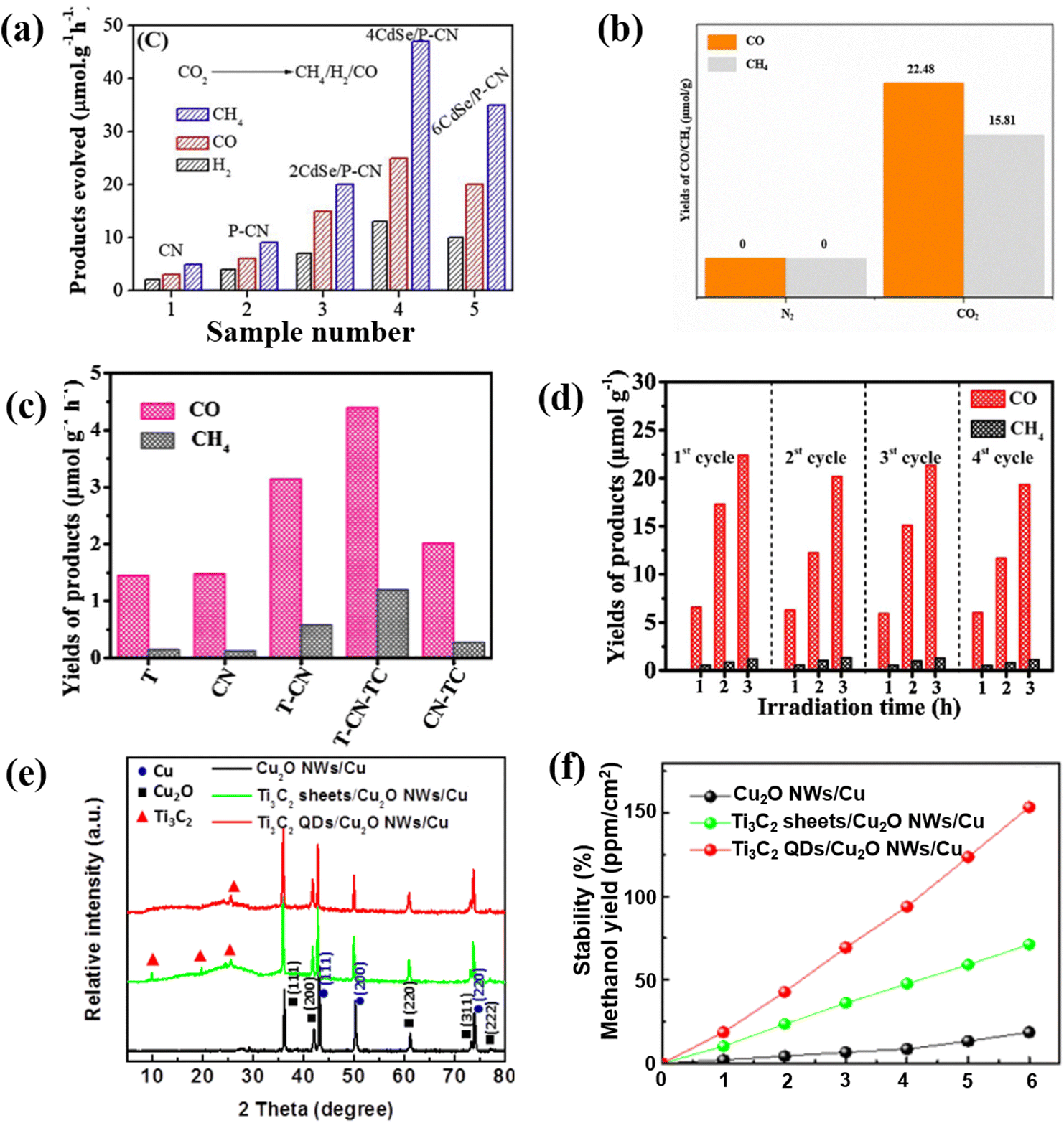 | ||
| Fig. 15 (a) Photocatalytic CO2 reduction activities of different carbon-based QDs.126 Reprinted with permission. Copyright 2020, Elsevier. (b) Results of CO2 photoreduction.131 Reprinted with permission. Copyright 2020, Springer. (c) Photocatalytic CO2 reduction of TCQDs and (d) cycle effect on photocatalytic CO2 degradation.135 Reprinted with permission. Copyright 2020, Elsevier. (e) XRD patterns of Ti3C2 QD-based photocatalysts and (f) the corresponding methanol yields.99 Reprinted with permission. Copyright 2018, Wiley-VCH GmbH. | ||
As a derivative of MXenes, MQDs have also been reported to be suitable for photocatalytic CO2 reduction.125–134 He et al. constructed the 2D/2D/0D TiO2/C3N4/Ti3C2 MXene heterojunction, in which the edge-capped 0D Ti3C2 QDs (TCQD) are grown on the surface of g-C3N4 through electrostatic interactions. The advantages of the heterogeneous structure in photocatalytic CO2 reduction are higher yields of CH4 and CO, as well as much better stability than a single precursor catalyst; this confirms the important role of the introduction of TCQD on improving the photocatalytic activity of TiO2/g-C3N4 (Fig. 15c and d).135 Furthermore, Cu0.05Zn2.95In2S6@Ti3C2OH QDs exhibit superior light utilization capability, and the highest efficient carrier separation and transfer capability. The CO yield of the optimized material is 51.848 μmol g−1 h−1, and the selectivity is up to 99%. This high yield is 22.3 times higher than that with Zn3In2S6. This indicates that Cu doping and Ti3C2OH have a synergistic effect and QD modification can enhance the reduction of CO2 to CO. The enhanced activity is mainly due to the Cu0.05Zn2.95In2S6@Ti3C2OH QDs having the strongest CO2 adsorption and activation abilities.136 Additionally, Zeng et al. successfully synthesized Ti3C2/Cu2O nanowires by the heterogeneous coupling of Ti3C2 QDs with Cu2O nanowires through a simple hydrothermal method. The results show that the existence of Ti3C2 QDs not only effectively improves the crystallization stability of Cu2O (Fig. 15e), but also significantly promotes the separation of photogenerated charges and reduces the band bending edge, thus greatly promoting the photocatalytic CO2 reduction activity (Fig. 15f).99 Compared with MQDs, CNQDs have the characteristics of higher yield when applied to photocatalytic CO2 reduction, while MQDs tend to have more prominent selectivity and stability, both of which have different advantages.
6.2. Photocatalytic pollutant degradation
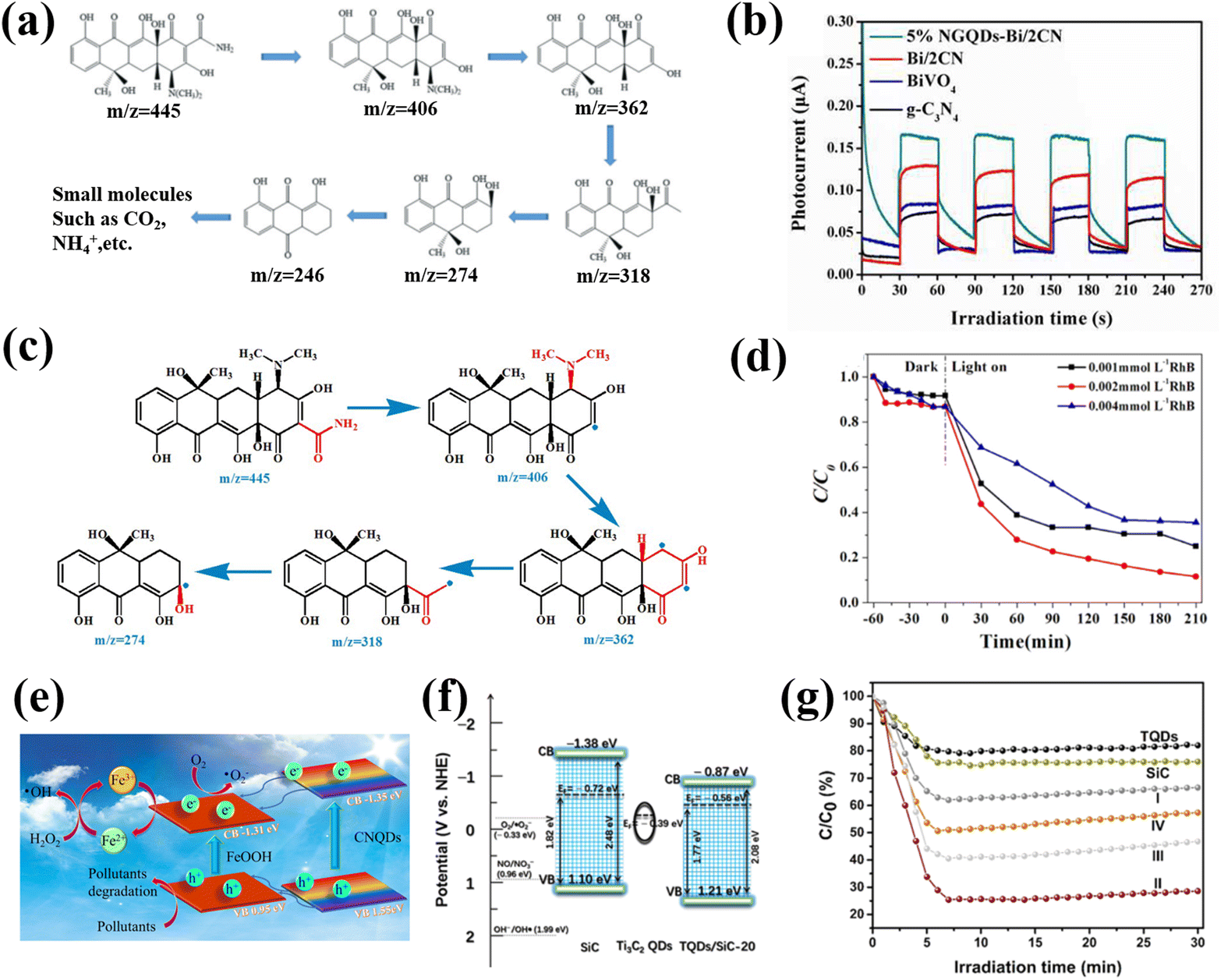
In the aquatic environment, organic pollutants pose a serious threat to the environment and human health. The degradation of pollutants has always been a hot issue in the field of photocatalysis.137,138 GQDs were the first materials applied to photocatalytic pollutant degradation. In early research, the simple S-GQD showed excellent photocatalytic performance for the degradation of basic fuchsin under visible light.139 Che and co-workers successfully constructed the Z-type g-C3N4/Bi2WO6 heterojunction using N-doped graphene QDs (NGQD) as a modifier through a simple hydrothermal method. Further analysis showed that NGQD could be employed as an effective carrier collector to significantly improve the electron–hole separation efficiency of the g-C3N4/Bi2WO6 heterojunction. Therefore, the NGQD modified Z-type g-C3N4/Bi2WO6 heterojunction shows excellent photocatalytic degradation activity, and can even remove various antibiotics, such as tetracycline (TC), ciprofloxacin (CIP), oxytetracycline (OTC), etc. (Fig. 16a), at the same time.140 One of the most effective ways to improve the photocatalytic performance of semiconductor photocatalysts is by coupling with other semiconductors to reduce electron–hole recombination. Yan et al. prepared nitrogen-doped GQDs to modify the BiVO4/g-C3N4 heterojunction and systematically explored the influence of chemical composition on the photocatalytic degradation effect. The corresponding results show that the 5% NGQD-Bi/2CN sample displays the highest photocatalytic efficiency and exhibits the highest photocurrent response when the Bi/CN ratio is 1![[thin space (1/6-em)]](https://www.rsc.org/images/entities/char_2009.gif) :2 (Fig. 16b). Subsequent free radical capture experiments showed that the presence of NGQDs accelerated the separation of carriers, thus showing a high degradation activity for the photocatalytic degradation of TC, OTC and CIP (Fig. 16c).141
:2 (Fig. 16b). Subsequent free radical capture experiments showed that the presence of NGQDs accelerated the separation of carriers, thus showing a high degradation activity for the photocatalytic degradation of TC, OTC and CIP (Fig. 16c).141
 | ||
| Fig. 16 (a) Schematic diagram of NGQD for photocatalytically degrading TC.140 Reprinted with permission. Copyright 2019, Elsevier. (b) Transient photocurrent response of different catalysts and (c) photocatalytic pathway of 5% NGQD-Bi/2CN for degrading TC.141 Reprinted with permission. Copyright 2016, Royal Society of Chemistry. (d) Photocatalytic degradation performances at different RhB concentrations.144 Reprinted with permission. Copyright 2019, Elsevier. (e) Schematic diagram of CNQD for photocatalytic degrading TC.145 Reprinted with permission. Copyright 2016, Elsevier. (f) Photocatalytic mechanism and (g) rate of Ti3C2 QD/SiC composite for degrading NO.137 Reprinted with permission. Copyright 2020, American Chemical Society. | ||
Moreover, CNQDs are commonly used in the photocatalytic degradation of organic compounds such as TC, RhB and NO.72,142–146 By calcining a mixture of P25 and melamine at 500 °C for 4 hours, Li successfully prepared a hybrid of g-C3N4 QDs and TiO2 (rTiO2). The results show that the 15% CNQD-rTiO2 (S 15) possesses the highest photocatalytic activity for the degradation of RhB and NO under visible light irradiation. The existence of CNQDs not only improves the ability to capture visible light, but also delays the recombination of photogenerated electron–hole pairs.142 The CNQD/Ag/Bi2MoO6 composites prepared by the team of Lin exhibited exceptional photocatalytic activity (100%) against RhB under visible light irradiation. The superior performance is attributed to the increased specific surface area caused by the loaded CNQDs and the effective expansion of the light absorption range.143 Li reported a modest green strategy for preparing the CNQD/BiVO4 heterostructure. Compared with pure BiVO4, the photocatalytic degradation of RhB and TC by the CNQD/BiVO4 composite is significantly improved, and the maximum degradation rate is close to 80% (Fig. 16d). The enhancement of the photocatalytic degradation activity could be due to the enhanced specific surface area, directional charge transfer, and accelerated carrier separation efficiency, resulting from the introduction of CNQDs.144 Zhao used a facile method to prepare CNQD/FeOOH. The composite material exhibits a highly efficient photo-Fenton effect when used to degrade organic pollutants, thereby promoting the enhancement of the photocatalytic effect (Fig. 16e). When CNQD/FeOOH was applied to degrade TC, the degradation efficiency of TC reached 89% within 2 min, which provided a new idea for studying the catalytic mechanism of CNQD complexes: using the Fenton effect to promote the separation of photogenerated carriers.145
In addition to GQDs and CNQDs, MQDs are also reported to be suitable for the photocatalytic degradation of pollutants. For example, Wang constructed a new heterojunction catalyst by incorporating Ti3C2 QDs onto the surface of SiC material. Photochemical test results confirmed that the coupling of Ti3C2 QDs could significantly improve the carrier separation efficiency (Fig. 16f). The corresponding theoretical calculation demonstrates that the introduction of Ti3C2 QDs is beneficial for the generation of superoxide radicals. Thus, the photocatalytic degradation rate of NO by the Ti3C2 QD/SiC composite is up to 74%, which is 3.1 times and 3.7 times higher than that of Ti3C2 QDs and SiC alone, respectively (Fig. 16g).137 These breakthroughs made with carbon-based QDs in the photocatalytic degradation of pollutants provide a great possibility for the synthesis and design of various nanomaterial catalysts, which can convert solar energy into chemical energy and contribute to environmental remediation.
6.3. Photocatalytic hydrogen evolution
Based on research on 2D carbon-based materials in recent years,138–156 carbon-based QDs have great application potential in photocatalytic hydrogen evolution. For instance, Zou et al. designed a series of novel N-GQD/g-C3N4 photocatalysts by changing the coupling ratio of N-GQDs. Among them, the 15N-CNU sample possesses the best photocatalytic hydrogen evolution rate, which is 2.16 times that of initial g-C3N4 (Fig. 17a and b).152 Metal-free and low-cost S-GQDs were prepared by Gliniak et al. Under direct sunlight, the hydrogen production rate was 18166 μmol h−1g−1.153 The photocatalytic hydrogen production rate of S-GQDs is undoubtedly the highest among carbon-based QDs. Wang et al. prepared boron-doped g-C3N4 QDs (BCNQDs) by a simple molten salt method using melamine and boron oxide as precursors. Impressively, the photocatalytic hydrogen evolution efficiency of the g-C3N4/BCNQD heterojunction is 58 times that of BCNQDs (Fig. 17c and d).154 The improved photocatalytic performance can be attributed to boron doping, which leads to a narrow energy band, and the existence of BCNQDs leads to effective charge separation and transfer efficiency.155
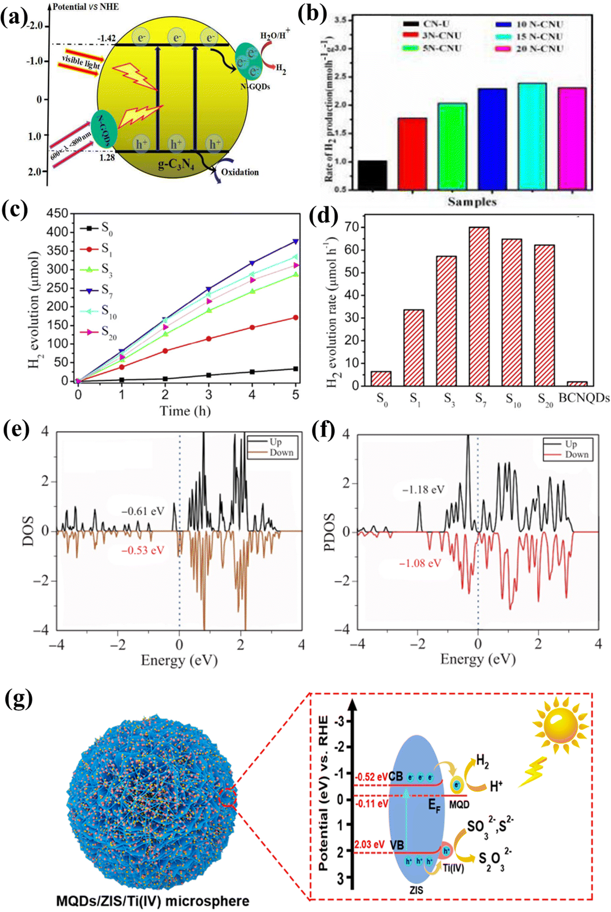 | ||
| Fig. 17 (a) Photocatalytic hydrogen evolution mechanism of NGQD/CN-U and (b) photocatalytic hydrogen evolution rates of NGQD-based samples.152 Reprinted with permission. Copyright 2016, Elsevier. (c and d) Photocatalytic hydrogen evolution rates of BCNQD-based heterojunction.154 Reprinted with permission. Copyright 2019, Elsevier. (e) Calculated PDOS of Ti3C2O QDs and (f) Ti a’ sites of Ti3C2O QD/G.156 Reprinted with permission. Copyright with 2021, Higher Education Press. (g) The mechanism of photocatalytic H2 evolution on the MQD/ZIS/Ti(IV).119 Reprinted with permission. Copyright with 2022, Elsevier. | ||
Zheng et al. designed Ti2CTx MQDs for alkaline electrocatalytic hydrogen evolution. It was found that the –Cl functional group was replaced by terminal O during the cathodic reaction of the Ti2CTx MQD/Cu2O/Cu catalyst to form the final stable Ti2CO MQD/Cu2O/Cu foam. DFT calculations showed that the active sites were O-functional sites on the surface of MQDs. Excellent electrocatalytic hydrogen evolution reduction activity comes from the adsorption and dissociation of water molecules promoted by transferring charges at the interface between MQDs and Cu2O.99 Kong et al. investigated the electronic structure and hydrogen evolution properties of Ti3C2O2 QD/graphene heterostructures using density functional theory. The results show that a slight distortion can be observed after the hybridization of graphene with QDs, which changes the electronic structure of QDs (Fig. 17e and f). The Ti3C2O2 QD–graphene interaction optimizes the catalytic activity of Ti3C2O2 QDs, thus achieving an excellent HER catalytic performance.156 On the other hand, due to electron transfer between the semiconductor components, the Z-scheme Ti-MOF/QD/ZIS photocatalyst achieved a high hydrogen production rate (2931.9 μmol g−1 h−1), and the high stability of the Ti-MOF/QD/ZIS composite photocatalyst was demonstrated by cycling tests.108 Based on previous studies, Li et al. reported that the photocatalytic HER rate of g-C3N4 nanosheets modified with MQDs was about 5111.8 μmol g−1 h−1.64 What is more fascinating is that the best photocatalytic hydrogen evolution rate of MQD/ZIS/Ti(IV) is 7.52 mmol g−1 h−1. Even in the presence of hole scavengers, the catalyst still shows excellent light stability compared with that promoted by metallic Pt. The remarkable enhancement of photocatalytic HER is attributed to the synergistic effect of 3D flower-shaped microspheres, amorphous Ti(IV) and active sites of MQDs (Fig. 17g).119 This study proves that MQDs can be used to catalyze HER; evolution is about three times as much as that of NGQDs and two times as much as BCNQDs, which opens up a new way to design semiconductors with surface-induced effects to obtain efficient photocatalysts, and provides more possibilities for the practical application of carbon-based QD photocatalysis technology.
6.4. Photocatalytic N2 reduction
As NH3 is widely used in industrial and agricultural markets, energy technologies are dedicated to the conversion of nitrogen (N2) into NH3 because of their green and environmentally friendly characteristics, and photocatalytic N2 reduction is a more effective way.Qin and co-workers prepared the Ti3C2 QD/Ni-MOF heterostructure, which showed a fairly high NH3 yield (88.79 μmol−1 h−1) (Fig. 18a).125 The e− in the Ti3C2 QD is transferred to the CB of the Ni-MOF nanosheets, and then N2 is injected under sunlight to obtain a more negative potential. Since the VB potential of Ni-MOF is significantly more correct than that of Ti3C2 QD, the excited h+ in the VB of Ni-MOF readily migrates to the VB of Ti3C2 QDS (Fig. 18b). At the same time, though XANES technology, it can be confirmed that the interaction between Ti3C2 QD and Ni MOF can accelerate electron transfer, and the Ni site could be the main region for the enrichment of electron density and the adsorption and activation of N2.125 Due to its outstanding adsorption energy of N2 (−3.18 eV), MXene acted as a source of N2 enrichment and electron transfer in this system to adjust the chemisorption equilibrium of N2 and NH3, thereby promoting the desorption of product NH3 and the efficiency of the active site (Fig. 18c). MXene/TiO2/Co-0.5% exhibited an excellent NH4+ formation rate (110 μmol g−1 h−1) and excellent stability in pure water under UV-vis light without using any hole sacrificing agent (Fig. 18d and e).157 Different from research by Qin,125 Gao et al.157 proposed for the first time to promote the process of photocatalytic N2 reduction by improving the resolution ability of NH3 by the catalyst, which is undoubtedly a significant step in the field of carbon-based QD photocatalytic nitrogen reduction. Table 3 presents a comparative analysis of the photocatalytic performance of different catalysts. The above results indicate that carbon-based QDs possess important development potential in the field of photocatalysis. With the progress of scientific research, we believe that carbon-based QDs will exhibit broad application prospects in the future.140,155–158
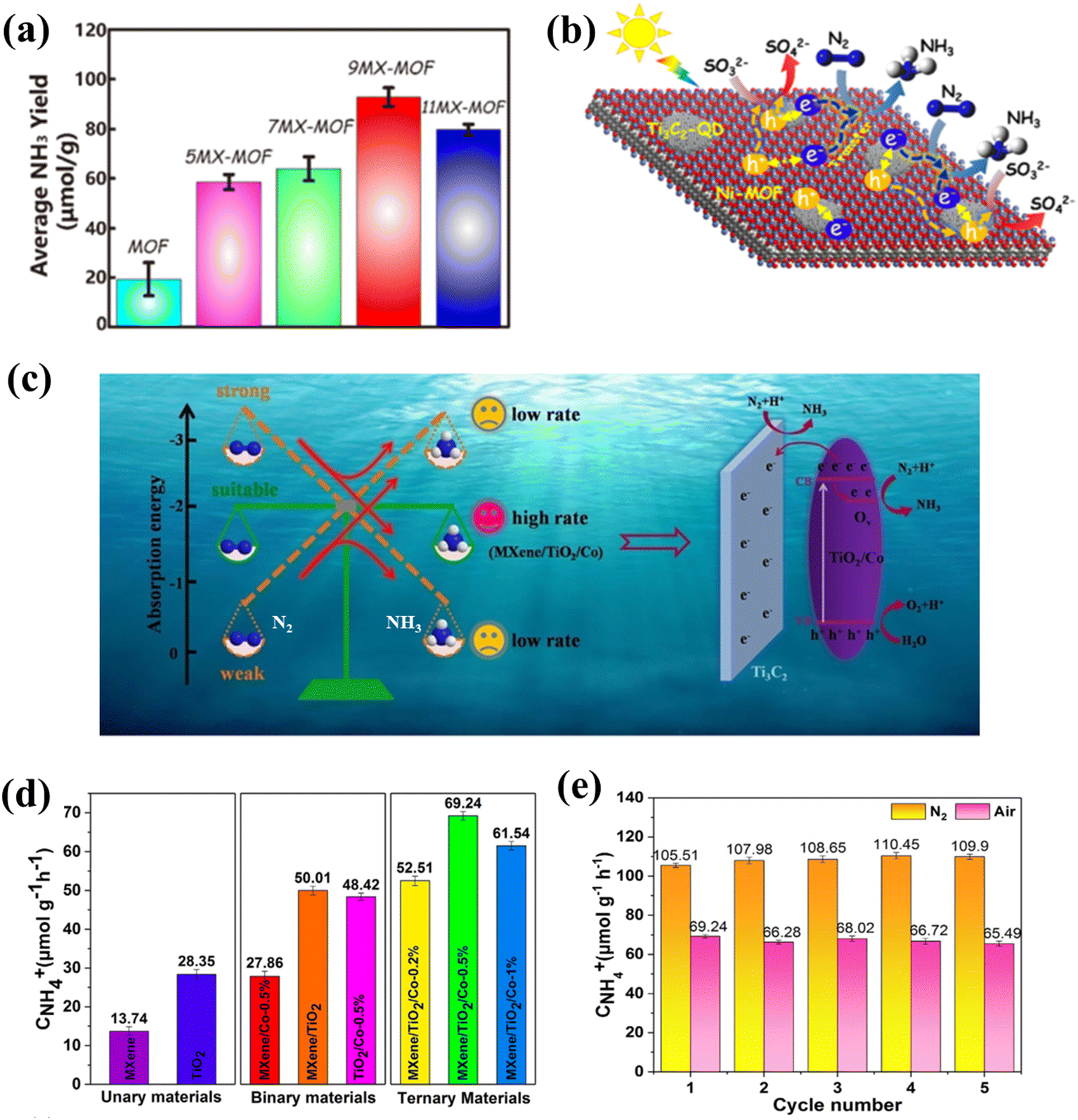 | ||
| Fig. 18 (a) Photocatalytic N2 reduction rates of Ti3C2-QD/Ni-MOF and (b) photocatalytic N2 reduction mechanism of Ti3C2-QD/Ni-MOF.125 Reprinted with permission. Copyright 2020, American Chemical Society. (c) Photocatalytic N2 reduction mechanism of MXene/TiO2/Co-0.5%, (d) photocatalytic N2 reduction rates of MXene/TiO2/Co-0.5%, and (e) the stability of N2 fixation of MXene/TiO2/Co-0.5%.157 Reprinted with permission. Copyright 2021, Elsevier. | ||
| Photocatalyst | Application | Photocatalyst efficiency | Production | Advantages | Disadvantages | Ref. |
|---|---|---|---|---|---|---|
| 4CdSe/P-CN | Photocatalytic carbon dioxide reduction | 47 μmol g−1 h−1 | CH4 | High selectivity | Low conversion rate | 126 |
| CNQD/CeO2 | Photocatalytic carbon dioxide reduction | 1.58 μmol g−1 h−1 | CH4 | Excellent carrier separation | Low productivity | 131 |
| TiO2/C3N4/Ti3C2 QDs | Photocatalytic carbon dioxide reduction | 4 μmol g−1 h−1 | CO | High stability | Low selectivity | 135 |
| Cu0.05Zn2.95In2S6@Ti3C2OH QDs | Photocatalytic carbon dioxide reduction | 51.848 μmol g−1 h−1 | CO | High selectivity, reactant adsorption | The preparation of red tape | 136 |
| Ti3C2 QD/Cu2O | Photocatalytic carbon dioxide reduction | — | CH3OH | Alleviates band bending | Large bandgap | 99 |
| NGQD/g-C3N4/Bi2WO3 | Photocatalytic pollutant degradation | Percent conversion: 89.1% | — | Absorbs near-infrared light | Without environmentally friendly synthesis path | 140 |
| GQD/BiVO4/g-C3N4 | Photocatalytic pollutant degradation | Percent conversion: 91.5% | — | Strong oxidation capacity, excellent carrier separation | Synthesis route is not safe enough | 141 |
| CNQD/Ag/Bi2MoO6 | Photocatalytic pollutant degradation | Percent conversion: 100% | — | Excellent carrier separation, high conversion | Catalysts are difficult to synthesize in large quantities | 143 |
| CNQD/FeOOH | Photocatalytic pollutant degradation | Percent conversion: 89% | — | Fast degradation, Fenton-like effect | Poor stability | 145 |
| Ti3C2 QD/SiC | Photocatalytic pollutant degradation | Percent conversion: 74% | — | Strong oxidation capacity, stable structure | Low degradation rate | 137 |
| NGQD/g-C3N4 | Photocatalytic hydrogen evolution | 2300 μmol g−1 h−1 | H2 | High productivity | Large bandgap | 152 |
| g-C3N4/BCNQD | Photocatalytic hydrogen evolution | 1400 μmol g−1 h−1 | H2 | Excellent carrier separation, narrow bandgap | Low productivity | 154 |
| MQD/g-C3N4 | Photocatalytic hydrogen evolution | 5111.8 μmol g−1 h−1 | H2 | High productivity | Catalysts cannot be prepared on a large scale, the synthesis process involves organic reagents | 64 |
| MQD/ZIS/Ti | Photocatalytic hydrogen evolution | 7520 μmol g−1 h−1 | H2 | High productivity, more active sites | Preparation method is not green enough | 109 |
| Ti3C2 QD/Ni-MOF | Photocatalytic N2 reduction | 88.79 μmol−1 h−1 | NH3 | Easy preparation of catalyst | Production rate is low | 125 |
| MXene/TiO2/Co | Photocatalytic N2 reduction | 110 μmol g−1 h−1 | NH3 | Strong nitrogen fixation property | Reaction conditions are demanding | 157 |
7. Conclusion and prospects
In this review, the structural properties, synthesis methods, modification strategies, mechanism analysis, and photocatalytic applications of carbon-based QDs are summarized. As a frontier branch of QD materials, carbon-based QDs have attracted increasing attention due to their outstanding physicochemical and excellent optoelectronic properties. The vigorous development of stripping technology promotes the formation of various carbon-based QDs, such as GQDs, MQDs, CNQDs, and GDQDs. These carbon-based QDs have many unique properties, such as low toxicity and good biocompatibility, laying the foundation for the wider application of QDs in photocatalysis. Despite these tremendous achievements, many fundamental technological gaps and challenges still remain in this alluring but nascent field. Based on the above summary, four challenges and limitations of carbon-based QDs are highlighted below (Fig. 19).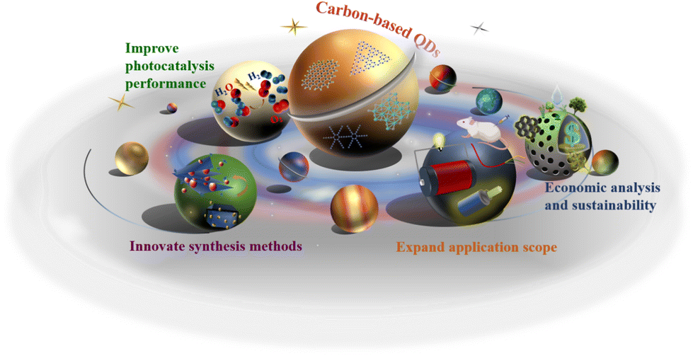 | ||
| Fig. 19 Challenges and prospects of carbon-based QDs. | ||
7.1. Innovation of synthesis methods
Many synthesis methods for carbon-based QDs remain to be explored. For instance, the removal degree of the Al layer and peeling level between MXenes layers are important factors affecting the subsequent preparation of MQDs. Similarly, GQDs or GDQDs are also prepared by etching massive precursors such as graphite, carbon nanotubes, and graphdiyne. There is currently no precise control method for interlayer exfoliation and etching processes of bulk precursors. In the future, researchers could focus on the optimization of exfoliation methods, in order to control the stripping scale of precursors during the preparation process for carbon-based QDs, so as to obtain carbon-based two-dimensional materials with controllable thickness, thereby realizing the large-scale fabrication of carbon-based QDs. In particular, research on the synthesis methods for GDQDs is missing due to the short time since their discovery. In the future, the synthesis shortcomings of carbon-based QDs should be studied laterally, such as the preparation of MXene QDs by combining molten salts with pyrolysis, or the development of new top-down synthesis techniques to prepare GDQDs. Additionally, a new method for synthesizing carbon-based QDs could be developed, allowing for more precise control of size, morphology, and surface defects.7.2. Improvement of photocatalytic performance
QDs are considered promising photocatalytic catalysts for CO2 reduction, H2 generation, and pollutant degradation. Therefore, the continuous improvement of the photocatalytic efficiency of carbon-based QDs will bring great advantages for energy utilization and environmental governance. In the future, researchers can improve on the photocatalytic performance of carbon-based QDs by refining the structural defects, controlling the type and number of surface-active sites and constructing complexes or heterojunctions. Additionally, the relatively low quantum yield (QY) of carbon-based nanomaterials cannot be ignored either. To date, the QYs of most carbon-based QDs reported in the literature are roughly in the range of 5%–60%, which is relatively low compared with other fluorophores, such as organic dyes and semiconductor QDs. In the future, scholars could try to modify the coating ligands on the surface of QDs and through this QDs might have relatively long carbon chains and organic ligands with greater steric hindrance. The fluorescence properties of QDs can also be improved by growing a shell material with a wide bandgap or doping elements, thus obtaining high-quality carbon-based QDs with improved QY.7.3. Expansion of application scope
Carbon-based QDs are biocompatible due to their unique nanostructures and diverse compositions, but there are still some challenges in applications. Typically, the toxicity of carbon-based QDs on organisms and the environment would limit their applications in sensing, biological imaging, photothermal therapy, and fluorescent devices. Previous studies have indicated that it is difficult to evaluate the in vitro toxicity of carbon-based QDs comprehensively. The toxicity and potential side effects of carbon-based QDs are not obvious at very low concentrations. The cytotoxic effects on organisms only become apparent at high concentrations (over 100 μg mL−1). Based on this, more studies are required to evaluate the toxic effects and associated safety issues of carbon-based QDs.159–161 Therefore, the establishment of a complete carbon-based QD toxicity evaluation system, and reparation strategies for the toxic effects of carbon-based QDs, etc., may still need further exploration, to broaden their application scope.7.4. Economic analysis and sustainability
Carbon-based quantum dots are mainly composed of common non-toxic elements, such as C and N, and thus, are not only environmentally friendly but also easy to prepare. Thus, the wide application of carbon-based quantum dots is in line with the current concept of the carbon cycle and the green sustainable social concept. Moreover, the high bonding energy of C endows carbon-based QDs with high catalytic stability, which is another major advantage for an ideal photocatalyst. However, current research on carbon-based QDs focuses on functionalization and photocatalytic conversion efficiency, but often ignores their potential economic benefits and environmental friendliness. Therefore, it is essential to further explore carbon-based quantum dots from the perspective of the environment. It is expected that a simple, economical, environmentally friendly and efficient synthesis method will be developed in the future to prepare carbon-based QDs with excellent photocatalytic activity.In conclusion, the ultimate value of carbon-based QDs will be realized by addressing the above-mentioned challenges. We expect more upcoming studies on the optical, biological, toxicological, and physical properties of carbon-based QDs. There is no doubt that the properties, applications, and devices based on carbon-based QDs will continue to be innovated, and they will find practical applications in many fields in the future.
Conflicts of interest
There are no conflicts of interest to declare.Acknowledgements
This work is supported by the National Natural Science Foundation of China (Grant Nos. 62004143, 21975084, 51672089), the Key R&D Program of Hubei Province (Grant No. 2022BAA084), the Central Government Guided Local Science and Technology Development Special Fund Project (Grant No. 2020ZYYD033), the Natural Science Foundation of Hubei Province (Grant No. 2021CFB133), the Opening Fund of Key Laboratory for Green Chemical Process of Ministry of Education of Wuhan Institute of Technology (Grant No. GCP202101), the Innovation Project of Engineering Research Center of Phosphorus Resources Development and Utilization of Ministry of Education (Grant No. LCX2021003) and the Open Research Fund of Key Laboratory of Material Chemistry for Energy Conversion and Storage (HUST), Ministry of Education (No. 2021JYBKF05).References
- J. Lee, K. Kim, W. I. Park, B. H. Kim, J. H. Park, T. H. Kim, S. Bong, C. H. Kim, G. S. Chae, M. Jun, Y. Hwang, Y. S. Jung and S. Jeon, Nano Lett., 2012, 12, 6078–6083 CrossRef CAS PubMed.
- R. K. Singh, R. Kumar, D. P. Singh, R. Savu and S. A. Moshkalev, Mater. Today Chem., 2019, 12, 282–314 CrossRef CAS.
- Y. Wang, Y. Liu, J. Zhang, J. Wu, H. Xu, X. Wen, X. Zhang, C. S. Tiwary, W. Yang, R. Vajtai, Y. Zhang, N. Chopra, I. N. Odeh, Y. Wu and P. M. Ajayan, Sci. Adv., 2017, 3, e1701500 CrossRef PubMed.
- R. Gui, H. Jin, Z. Wang and J. Li, Chem. Soc. Rev., 2018, 47, 6795–6823 RSC.
- V. C. Hoang, K. Dave and V. G. Gomes, Nano Energy, 2019, 66, 104093 CrossRef CAS.
- N. Chouhan, C. L. Yeh, S. F. Hu, R. S. Liu, W. S. Chang and K. H. Chen, Chem. Commun., 2011, 47, 3493–3495 RSC.
- W. Liao, B. Wang and Z. Liu, Int. J. Hydrogen Energy, 2017, 42, 10962–10970 CrossRef CAS.
- J. Zhang, G. Y. Hao, C. Yao, J. Yu, J. Wang, W. Yang, C. Hu and B. Zhang, ACS Appl. Mater. Interfaces, 2016, 8, 16612–16621 CrossRef CAS.
- L. Ding, P. J. Zhou, H. J. Zhan, C. Chen, W. Hu, T. F. Zhou and C. W. Lin, J. Lumin., 2013, 142, 167–172 CrossRef CAS.
- D. Das and A. Samanta, Phys. Chem. Chem. Phys., 2015, 17, 5063–5071 RSC.
- Q. Xue, H. Zhang, M. Zhu, Z. Pei, H. Li, Z. Wang, Y. Huang, Q. Deng, J. Zhou, S. Du, Q. Huang and C. Zhi, Adv. Mater., 2017, 29, 1604847 CrossRef PubMed.
- M. Wu, Y. Wang, W. Wu, C. Hu, X. Wang, J. Zheng, Z. Li, B. Jiang and J. Qiu, Carbon, 2014, 78, 480–489 CrossRef CAS.
- L. A. Ponomarenko, F. Schedin, M. I. Katsnelson, R. Yang, E. W. Hill, K. S. Novoselov and A. K. Geim, Science, 2008, 320, 356–358 CrossRef CAS PubMed.
- L. Li, G. Wu, G. Yang, J. Peng, J. Zhao and J. J. Zhu, Nanoscale, 2013, 5, 4015–4039 RSC.
- T. Wu, X. Pang, S. Zhao, S. Xu, Z. Liu, Y. Li and F. Huang, Small Struct., 2022, 3, 2100206 CrossRef CAS.
- S. Gu, C. T. Hsieh, Y. A. Gandomi, J. K. Chang, J. Li, J. Li, H. Zhang, Q. Guo, K. C. Lauh and R. Pandey, J. Mater. Chem. C, 2019, 7, 5468–5476 RSC.
- B. Yu, A. Huang, D. Chen, K. Srinivas, X. Zhang, X. Wang, B. Wang, F. Ma, C. Liu, W. Zhang, J. He, Z. Wang and Y. Chen, Small, 2021, 17, 2100460 CrossRef CAS PubMed.
- B. Geng, P. Li, F. Fang, W. Shi, J. Glowacki, D. Pan and L. Shen, Carbon, 2021, 184, 375–385 CrossRef CAS.
- H. Li, G. Huang, H. Xu, Z. Yang, X. Xu, J. Li, A. Qu and Y. Chen, J. Solid State Chem., 2020, 292, 121705 CrossRef CAS.
- G. Li, Z. Lian, W. Wang, D. Zhang and H. Li, Nano Energy, 2016, 19, 446–454 CrossRef CAS.
- Y. Lv, X. Wu, H. Lin, J. Li, H. Zhang, J. Guo, D. Jia and H. Zhang, Small, 2021, 17, 2006442 CrossRef CAS.
- G. Cai, Z. Yu, P. Tong and D. Tang, Nanoscale, 2019, 11, 15659–15667 RSC.
- X. Chen, J. Li, G. Pan, W. Xu, J. Zhu, D. Zhou, D. Li, C. Chen, G. Lu and H. Song, Sens. Actuators, B, 2019, 289, 131–137 CrossRef CAS.
- Z. Miao, G. Wang, X. Zhang and X. Dong, Appl. Surf. Sci., 2020, 528, 146929 CrossRef CAS.
- S. Zhu, Y. Song, X. Zhao, J. Shao, J. Zhang and B. Yang, Nano Res., 2015, 8, 355–381 CrossRef CAS.
- S. Y. Lim, W. Shen and Z. Gao, Chem. Soc. Rev., 2015, 44, 362–381 RSC.
- J. Jiang, N. Li, J. Zou, X. Zhou, G. Eda, Q. Zhang, H. Zhang, L. Li, T. Zhai and A. T. S. Wee, Chem. Soc. Rev., 2019, 48, 4639–4654 RSC.
- J. Shen, Y. Zhu, X. Yang and C. Li, Chem. Commun., 2012, 31, 3686–3699 RSC.
- P. Namdari, B. Negahdari and A. Eatemadi, Biomed. Pharmacother., 2017, 87, 209–222 CrossRef CAS PubMed.
- T. Gao, X. Wang, L. Y. Yang, H. He, X. X. Ba, J. Zhao, F. L. Jiang and Y. Liu, ACS Appl. Mater. Interfaces, 2017, 9, 24846–24856 CrossRef CAS PubMed.
- A. K. Geim and K. S. Novoselov, Nat. Mater., 2007, 6, 183–191 CrossRef CAS PubMed.
- A. H. C. Neto, F. Guinea, N. M. R. Peres, K. S. Novoselov and A. K. Geim, Rev. Mod. Phys., 2009, 81, 109 CrossRef.
- J. Peng, W. Gao, B. K. Gupta, Z. Liu, R. Romero-Aburto, L. Ge, L. Song, L. B. Alemany, X. Zhan, G. Gao, S. A. Vithayathil, B. A. Kaipparettu, A. A. Marti, T. Hayashi, J. J. Zhu and P. M. Ajayan, Nano Lett., 2012, 12, 844–849 CrossRef CAS.
- T. F. Yeh, S. J. Chen and H. Teng, Nano Energy, 2015, 12, 476–485 CrossRef CAS.
- J. Zou, S. Wu, Y. Liu, Y. Sun, Y. Cao, J. P. Hsu, A. T. S. Wee and J. Jiang, Carbon, 2018, 130, 652–663 CrossRef CAS.
- J. Jiang, L. Ou-yang, L. Zhu, A. Zheng, J. Zou, X. Yi and H. Tang, Carbon, 2014, 80, 213–221 CrossRef CAS.
- E. Kroke, M. Schwarz, E. Horath-Bordon and P. Kroll, New J. Chem., 2002, 26, 508–512 RSC.
- Q. Cui, J. Xu, X. Wang, L. Li, M. Antonietti and M. Shalom, Angew. Chem., Int. Ed., 2016, 55, 3672–3676 CrossRef CAS PubMed.
- L. He, M. Fei, J. Chen, Y. Tian, Y. Jiang, Y. Huang, K. Xu, J. Hu, Z. Zhao, Q. Zhang, H. Ni and L. Chen, Mater. Today, 2019, 22, 76–84 CrossRef CAS.
- J. Zhou, W. Cai, J. Ding, H. Wan and G. Guan, J. Environ. Chem. Eng., 2021, 9, 105292 CrossRef CAS.
- W. Wang, J. C. Yu, Z. Shen, D. K. L. Chan and T. Gu, Chem. Commun., 2014, 50, 10148–10150 RSC.
- J. Zhou, Y. Yang and C. Zhang, Chem. Commun., 2013, 49, 8605–8607 RSC.
- B. Anasori, M. R. Lukatskaya and Y. Gogotsi, Nat. Rev. Mater., 2017, 2, 16098 CrossRef CAS.
- Y. Qin, Z. Wang, N. Liu, Y. Qin, Z. Wang, N. Liu, Y. Sun, D. Han, Y. Liu, L. Niu and Z. Kang, Nanoscale, 2018, 10, 14000–14004 RSC.
- S. Bai, M. Yang, J. Jiang, X. He, J. Zou, Z. Xiong, G. Liao and S. Liu, npj 2D Mater. Appl., 2021, 5, 78 CrossRef CAS.
- J. Zou, J. Wu, Y. Wang, F. Deng, J. Jiang, Y. Zhang, S. Liu, N. Li, H. Zhang, J. Yu, T. Zhai and H. N. Alshareef, Chem. Soc. Rev., 2022, 51, 2972–2990 RSC.
- J. Jiang, S. Bai, M. Yang, J. Zou, N. Li, J. Peng, H. Wang, K. Xiang, S. Liu and T. Zhai, Nano Res., 2022, 15, 5977–5986 CrossRef CAS.
- Y. Liu, W. Zhang and W. Zheng, Nano-Micro Lett., 2022, 14, 158 CrossRef CAS PubMed.
- P. Wang, D. Zhao, X. Hui, Z. Qian, P. Zhang, Y. Ren, Y. Lin, Z. Zhang and L. Yin, Adv. Energy Mater., 2021, 11, 2003069 CrossRef CAS.
- J. Jiang, S. Bai, J. Zou, S. Liu, J. P. Hsu, N. Li, G. Zhu, Z. Zhuang, Q. Kang and Y. Zhang, Nano Res., 2022, 15, 6551–6567 CrossRef CAS.
- B. Shao, Z. Liu, G. Zeng, H. Wang, Q. Liang, Q. He, M. Cheng, C. Zhou, L. Jiang and B. Song, J. Mater. Chem. A, 2020, 8, 7508–7535 RSC.
- J. Jiang, F. Li, S. Bai, Y. Wang, K. Xiang, H. Wang, J. Zou and J.-P. Hsu, Nano Res., 2022 DOI:10.1007/s12274-022-5112-x.
- G. Deysher, S. Sin, Y. Gogotsi and B. Anasori, Mater. Today, 2018, 21, 1064–1065 CrossRef.
- J. Jiang, Z. Xiong, H. Wang, K. Xiang, P. Wu and J. Zou, Sci. China: Technol. Sci., 2022, 65, 3020–3028 CrossRef CAS.
- J. Jiang, F. Li, J. Zou, S. Liu, J. Wang, K. Xiang, H. Zhang, Y. Zhang, X. Fu and J.-P. Hsu, Sci. China Mater., 2022, 65, 2895–2910 CrossRef.
- Y. Liu, X. Zhang, W. Zhang, X. G. Y. Wang, X. Zou, X. Zhou and W. Zheng, Energy Environ. Sci., 2022 DOI:10.1002/eem2.12432.
- Z. Zeng, Y. Yan, J. Chen, P. Zan, Q. Tian and P. Chen, Adv. Funct. Mater., 2019, 29, 1806500 CrossRef.
- H. Min, Y. Qi, Y. Chen, Y. Zhang, X. Han, Y. Xu, Y. Liu, J. Hu, H. Liu, Y. Li and G. Nie, ACS Appl. Mater. Interfaces, 2019, 11, 32798–32807 CrossRef CAS PubMed.
- X. Zhang, Q. Wang, Z. Jin, Y. Chen, H. Liu, J. Wang, Y. Li and S. Liu, Adv. Mater. Interfaces, 2017, 5, 1701117 CrossRef.
- X. Chen, W. J. Ong, Z. Kong, X. Zhao and N. Li, Sci. Bull., 2020, 65, 45–54 CrossRef CAS.
- T. Wang, C. Nie, Z. Ao, S. Wang and T. An, J. Mater. Chem. A, 2020, 8, 485–502 RSC.
- S. Ge, J. He, C. Ma, J. Liu, F. Xi and X. Dong, Talanta, 2019, 199, 581–589 CrossRef CAS PubMed.
- X. Lin, D. Xu, J. Zheng, M. Song, G. Che, Y. Wang, Y. Yang, C. Liu, L. Zhao and L. Chang, J. Alloys Compd., 2016, 688, 891–898 CrossRef CAS.
- Y. Li, L. Ding, Y. Guo, Z. Liang, H. Cui and J. Tian, ACS Appl. Mater. Interfaces, 2019, 11, 41440–41447 CrossRef CAS PubMed.
- B. Sapkota, A. Benabbas, H. Y. G. Lin, W. Liang, P. Champion and M. Wanunu, ACS Appl. Mater. Interfaces, 2017, 9, 9378–9387 CrossRef CAS PubMed.
- H. Wang, X. Yuan, H. Wang, X. Chen, Z. Wu, L. Jiang, W. Xiong and G. Zeng, Appl. Catal., B, 2016, 193, 36–46 CrossRef CAS.
- G. P. Neupane, B. Wang, M. Tebyetekerwa, H. T. Nguyen, M. Taheri, B. Liu, M. Nauman and R. Basnet, Small, 2021, 17, 2006309 CrossRef CAS PubMed.
- X. Chen, J. Li, G. Pan, W. Xua, J. Zhu, D. Zhou, D. Li, C. Chen, G. Lu and H. Song, Sens. Actuators, B, 2019, 289, 131–137 CrossRef CAS.
- M. B. Soquetta, S. Schmaltz, F. W. Righes, R. Salvalaggio and L. D. M. Terra, J. Food Process. Preserv., 2018, 42, e13393 CrossRef.
- S. Zhuo, M. Shao and S. T. Lee, ACS Nano, 2012, 6, 1059–1064 CrossRef CAS PubMed.
- Z. Wang, J. Xuan, Z. Zhao, Q. Li and F. Geng, ACS Nano, 2017, 11, 11559–11565 CrossRef CAS PubMed.
- S. Gu, C. T. Hsieh, C. Y. Yuan, Y. A. Gandomi, J. K. Chang, C. C. Fu, J. W. Yang and R. S. Juang, J. Lumin., 2020, 217, 116774 CrossRef CAS.
- Y. C. Lu, J. Chen, A. J. Wang, N. Bao, J. J. Feng, W. Wang and L. Shao, J. Mater. Chem. C, 2015, 3, 73–78 RSC.
- Y. Wang, C. Li, X. Han, D. Liu, H. Zhao, Z. Li, P. Xu and Y. Du, ACS Appl. Nano Mater., 2018, 1, 5366–5376 CrossRef CAS.
- M. He, X. Guo, J. Huang, H. Shen, Q. Zeng and L. Wang, Carbon, 2018, 140, 508–520 CrossRef CAS.
- X. Li, F. Liu, D. Huang, N. Xue, Y. Dang, M. Zhang, L. Zhang, B. Li, D. Liu, L. Wang, H. Liu and X. Tao, Adv. Funct. Mater., 2020, 30, 2000308 CrossRef CAS.
- T. Zhang, X. Jiang, G. Li, Q. Yao and J. Y. Lee, ChemNanoMat, 2018, 4, 56–60 CrossRef CAS.
- P. Pandey, A. Sengupta, S. Parmar, U. Bansode, S. Gosavi, A. Swarnkar, S. Muduli and A. D. Mohite, ACS Appl. Nano Mater., 2020, 3, 3305–3314 CrossRef CAS.
- K. Nekoueian, M. Amiri, M. Sillanpää, F. Marken, R. Boukherroub and S. Szunerits, Chem. Soc. Rev., 2019, 48, 4281–4316 RSC.
- G. L. Hong, H. L. Zhao, H. H. Deng, H. J. Yang, H. P. Peng, Y. H. Liu and W. Chen, Int. J. Nanomed., 2018, 13, 4807–4815 CrossRef CAS PubMed.
- A. Xu, G. Wang, Y. Li, H. Dong, S. Yang, P. He and G. Ding, Small, 2020, 16, 2004621 CrossRef CAS PubMed.
- B. Liu, X. Tang, G. Cai, L. Wen, Y. Song and X. Zhao, J. Hazard. Mater., 2009, 169, l112–1118 Search PubMed.
- B. Bayatsarmadi, Y. Zheng, A. Vasileff and S.-Z. Qiao, Small, 2017, 13, 1700191 CrossRef PubMed.
- D. Qu, Z. Sun, M. Zheng, J. Li, Y. Zhang, G. Zhang, H. Zhao, X. Liu and Z. Xie, Adv. Opt. Mater., 2015, 3, 360–367 CrossRef CAS.
- B. Huang, J. He, S. Bian, C. Zhou, Z. Li, F. Xi, J. Liu and X. Dong, Chin. Chem. Lett., 2018, 29, 1698–1701 CrossRef CAS.
- L. Zhao, Z. Wang, Y. Li, S. Wang, L. Wang, Z. Qi, Q. Ge, X. Liu and J. Z. Zhang, J. Mater. Sci. Technol., 2021, 78, 30–37 CrossRef CAS.
- Q. Bai, H. Luo, X. Yi, S. Shi, L. Wang, M. Liu, F. Du, Z. Yang and N. Sui, Microchem. J., 2022, 179, 107521 CrossRef CAS.
- P. Kumar, P. Kar, A. P. Manuel, S. Zeng, U. K. Thakur, K. M. Alam, Y. Zhang, R. Kisslinger, K. Cui, G. M. Bernard, V. K. Michaelis and K. Shankar, Adv. Opt. Mater., 2019, 8, 1901275 CrossRef.
- F. Montejo-Alvaro, J. Oliva, M. Herrera-Trejo, H. M. Hdz-García and A. I. Mtz-Enriquez, Theor. Chem. Acc., 2019, 138, 37 Search PubMed.
- R. Abbass, H. H. C. Alkaaby, Z. J. Kadhim, S. E. Izzat, A. A. Kadhim, A. H. Adhab and P. Pakravan, J. Mol. Graphics Modell., 2022, 117, 108302 CrossRef CAS PubMed.
- R. Tang, S. Zhou, C. Li, R. Chen, L. Zhang, Z. Zhang and L. Yin, Adv. Funct. Mater., 2020, 30, 2000637 CrossRef CAS.
- M. Humayun, C. Wang and W. Luo, Small Methods, 2022, 6, 2101395 CrossRef CAS PubMed.
- H. Huang, L. Liao, X. Xu, M. Zou, F. Liu and N. Li, Talanta, 2013, 117, 152–157 CrossRef CAS PubMed.
- Z. Jin, C. Liu, Z. Liu, J. Han, Y. Fang, Y. Han, Y. Niu, Y. Wu, C. Sun and Y. Xu, Adv. Energy Mater., 2020, 10, 2000797 CrossRef CAS.
- J. Liu, Y. Liu, N. Liu, Y. Han, X. Zhang, H. Huang, Y. Lifshitz, S. Lee, J. Zhong and Z. Kang, Science, 2015, 347, 6225 Search PubMed.
- B. Chang, Y. Guo, H. Liu, L. Li and B. Yang, J. Mater. Chem. A, 2022, 10, 3134 RSC.
- X. Guo, H. Gao, S. Wang, G. Yang, X. Zhang, J. Zhang, H. Liu and G. Wang, Nano Lett., 2022, 22, 1225–1232 CrossRef CAS PubMed.
- J. Wen, J. Xie, X. Chen and X. Li, Appl. Surf. Sci., 2017, 391, 72–123 CrossRef CAS.
- Y. Liu, X. Zhang, W. Zhang, X. Ge, Y. Wang, X. Zou, X. Zhou and W. Zheng, Energy Environ. Mater., 2022 DOI:10.1002/eem2.12438.
- J. Huang, G. Nie and Y. Ding, Catalysts, 2020, 10, 6 CrossRef CAS.
- A. Ghaffarkhah, E. Hosseini, M. Kamkar, A. A. Sehat, S. Dordanihaghighi, A. Allahbakhsh, C. Kuur and M. Arjmand, Small, 2022, 18, 2102683 CrossRef CAS PubMed.
- T. F. Yeh, C. Y. Teng, S. J. Chen and H. Teng, Adv. Mater., 2014, 26, 3297–3303 CrossRef CAS PubMed.
- L. C. Chen, C. Y. Teng, C. Y. Lin, H. Y. Chang, S. J. Chen and H. Teng, Adv. Energy Mater., 2016, 6, 1600719 CrossRef.
- S. Liu, X. Jiang, G. I. N. Waterhouse, Z.-M. Zhang and L. Yu, Sep. Purif. Technol., 2022, 294, 121094 CrossRef CAS.
- L. Zhou, Y. Tian, J. Lei, L. Wang, Y. Liu and J. Zhang, Catal. Sci. Technol., 2018, 8, 2617 RSC.
- Y. Nie, Z. Liang, P. Wang, Q. Ma and X. Su, Anal. Chem., 2021, 93, 17086–17093 CrossRef CAS PubMed.
- Y. Liu, Y. Gong, X. Cui, H. Yu, W. Qin, X. Cui and M. Huo, J. Taiwan Inst. Chem. Eng., 2019, 138, 104457 CrossRef.
- S. Liu, X. Jiang, G. I. N. Waterhouse, Z. M. Zhang and L. Yu, Sep. Purif. Technol., 2022, 294, 121094 CrossRef CAS.
- M. Majdoub, Z. Anfar and A. Amedlous, ACS Nano, 2020, 14, 12390–12469 CrossRef CAS PubMed.
- F. Ai, C. Fu, G. Cheng, H. Zhang, Y. Feng, X. Yan and X. Zheng, ACS Appl. Nano Mater., 2021, 4, 8192–8199 CrossRef CAS.
- C. Guan, X. Yue, J. Fan and Q. Xiang, Chin. J. Catal., 2022, 43, 2484–2499 CrossRef CAS.
- H. Yu, Y. Xue and Y. Li, Adv. Mater., 2019, 31, 1803101 CrossRef CAS PubMed.
- P. Shandilya, P. Mandyal, V. Kumar and M. Sillanpaa, Sep. Purif. Technol., 2022, 281, 119825 CrossRef CAS.
- Y. Cui, X. Huang, T. Wang, L. Jia, Q. Nie, Z. Tan and H. Yu, Carbon, 2022, 191, 502–514 CrossRef CAS.
- Q. Xu, L. Ding, Y. Wen, W. Yang, H. Zhou, X. Chen, J. Street, A. Zhou, W.-J. Ong and N. Li, J. Mater. Chem. C, 2018, 6, 6360–6369 RSC.
- M. Ghashghaee, Z. Azizi and M. Ghambarian, J. Phys. Chem. Solids, 2020, 141, 109422 CrossRef CAS.
- Q. Xu, L. Ding, Y. Wen, W. Yang, H. Zhou, X. Chen, J. Street, A. Zhou, W.-J. Ong and N. Li, J. Mater. Chem. C, 2018, 6, 6360 RSC.
- M. L. O. Ne, A. G. Elhachimi, M. Boujnah, A. Benyoussef and A. E. Kenz, Optik, 2018, 158, 693–698 CrossRef.
- L. Yang, Z. Chen, X. Wang and M. Jin, Nanomaterials, 2022, 12, 542 CrossRef CAS PubMed.
- Y. Hu, W. Chen, T. Lei, Y. Jiao, H. Wang, X. Wang, G. Rao, X. Wang, B. Chen and J. Xiong, Nano Energy, 2020, 68, 104373 CrossRef CAS.
- S. Lu, L. Sui, Y. Liu, X. Yong, G. Xiao, K. Yuan, Z. Liu, B. Liu, B. Zou and B. Yang, Adv. Sci., 2019, 6, 1801470 CrossRef PubMed.
- J. Barrera, D. Ibañez, A. Heras, V. Ruiz and A. Colina, J. Phys. Chem. Lett., 2017, 8, 531–537 CrossRef CAS PubMed.
- P. Cai, J. Li, J. Huang, J. Chen, Y. Ding, X. Peng and Z. Wen, Small, 2022, 18, 2201144 CrossRef CAS PubMed.
- W. He, Y. Wei, J. Xiong, Z. Tang, Y. Wang, X. Wang, J. Deng, X. Yu, X. Zhang and Z. Zhao, Sep. Purif. Technol., 2022, 300, 121850 CrossRef CAS.
- J. Qin, B. Liu, K.-H. Lam, S. Song, X. Li and X. Hu, ACS Sustainable Chem. Eng., 2020, 8, 17791–17799 CrossRef CAS.
- F. Raziq, A. Hayat, M. Humayun, S. K. B. Mane, M. B. Faheem, A. Alie, Y. Zhao, S. Han, C. Cai, W. Li, D. C. Qi, J. Yi, X. Yu, M. B. H. Breese, F. Hassan, F. Ali, A. Mavlonov, K. Dhanabalan, X. Xiang, X. Zu, S. Li and L. Qiao, Appl. Catal., B, 2020, 270, 118867 CrossRef CAS.
- Y. N. Gong, B. Z. Shao, J. H. Mei, W. Yang, D. C. Zhong and T. B. Lu, Nano Res., 2022, 15, 551–556 CrossRef CAS.
- Q. Wang, Z. Fang, X. Zhao, C. Dong, Y. Li, C. Guo, Q. Liu, F. Song and W. Zhang, ACS Appl. Mater. Interfaces, 2021, 13, 59855–59866 CrossRef CAS PubMed.
- P. Zhang, J. Hu, Y. Shen, X. Yang, J. Qu, F. Du, W. Sun and C. M. Li, ACS Appl. Mater. Interfaces, 2021, 13, 46650–46658 CrossRef CAS PubMed.
- Q. Liang, Z. Li, Y. Bai, Z. H. Huang, F. Kang and Q. H. Yang, Sci. China Mater., 2017, 60, 109–118 CrossRef CAS.
- H. Jiang, X. Li, S. Chen, S. Chen, H. Wang and P. Huo, J. Mater. Sci.: Mater. Electron., 2020, 31, 20495–20512 CrossRef.
- Y. Wei, X. Li, Y. Zhang, Y. Yan, P. Huo and H. Wang, Renewable Energy, 2021, 179, 756–765 CrossRef CAS.
- M. Que, Y. Zhao, Y. Yang, L. Pan, W. Lei, W. Cai, H. Yuan, J. Chen and G. Zhu, ACS Appl. Mater. Interfaces, 2021, 13, 6180–6187 CrossRef CAS PubMed.
- V. Parey, B. M. Abraham, S. H. Mir and J. K. Singh, ACS Appl. Mater. Interfaces, 2021, 13, 35585–35594 CrossRef CAS PubMed.
- F. He, B. Zhu, B. Cheng, J. Yu, W. Ho and W. Macyk, Appl. Catal., B, 2020, 272, 119006 CrossRef CAS.
- J. Yang, Y. Hou, J. Sun, T. Liang, T. Zhu, J. Liang, X. Lu, Z. Yu, H. Zhu and S. Wang, Chem. Eng. J., 2023, 452, 139522 CrossRef CAS.
- H. Wang, R. Zhao, H. Hu, X. Fan, D. Zhang and D. Wang, ACS Appl. Mater. Interfaces, 2020, 12, 40176–40185 CrossRef CAS PubMed.
- Z. Huang, M. Shen, J. Liu, J. Ye and T. F. Asefa, J. Mater. Chem. A, 2021, 9, 14841–14850 RSC.
- B. Huang, J. He, S. Bian, C. Zhou, Z. Li, F. Xi, J. Liu and X. Dong, Chin. Chem. Lett., 2018, 29, 1698–1701 CrossRef CAS.
- H. Che, C. Liu, W. Hu, H. Hu, J. Li, J. Dou, W. Shi, C. Li and H. Dong, Catal. Sci. Technol., 2018, 8, 622–631 RSC.
- M. Yan, F. Zhu, W. Gu, L. Sun, W. Shi and Y. Hua, RSC Adv., 2016, 6, 61162–61174 RSC.
- Y. Li, K. Lv, W. Ho, F. Dong, X. Wu and Y. Xia, Appl. Catal., B, 2017, 202, 611–619 CrossRef CAS.
- X. Lin, D. Xu, R. Zhao, Y. Xi, L. Zhao, M. Song, H. Zhai, G. Che and L. Chang, Sep. Purif. Technol., 2017, 178, 163–168 CrossRef CAS.
- C. Li, H. Che, C. Liu, G. Che, P. A. Charpentier, W. Z. Xu, X. Wang and L. Liu, J. Taiwan Inst. Chem. Eng., 2019, 95, 669–681 CrossRef CAS.
- P. Zhao, B. Jin, Q. Zhang and R. Peng, Appl. Surf. Sci., 2022, 586, 152792 CrossRef CAS.
- X. Lin, D. Xu, R. Zhao, Y. Xi, L. Zhao, M. Song, H. Zhai, G. Che and L. Chang, Sep. Purif. Technol., 2017, 178, 163–168 CrossRef CAS.
- N. Li, J. Peng, W.-J. Ong, T. Ma, Arramel, P. Zhang, J. Jiang, X. Yuan and C. (John) Zhang, Matter, 2021, 4, 377–407 CrossRef CAS.
- J. Jiang, Z. Xiong, H. Wang, G. Liao, S. Bai, J. Zou, P. Wu, P. Zhang and X. Li, J. Mater. Sci. Technol., 2022, 118, 15–24 CrossRef.
- J. Zou, G. Liao, J. Jiang, Z. Xiong, S. Bai, H. Wang, P. Wu, P. Zhang and X. Li, Chin. J. Struct. Chem., 2022, 41, 2201025–2201033 CAS.
- J. Jiang, Y. Zou, Arramel, F. Li, J. Wang, J. Zou and N. Li, J. Mater. Chem. A, 2021, 9, 24195–24214 RSC.
- J. Wang, Q. Qin, F. Li, Y. Anjarsari, W. Sun, R. Azzahiidah, J. Zou, K. Xiang, H. Ma, J. Jiang and Arramel, Carbon Lett., 2022 DOI:10.1007/s42823-022-00401-2.
- J. P. Zou, L. C. Wang, J. Luo, Y. C. Nie, Q. J. Xing, X. B. Luo, H. M. Du, S. L. Luo and S. L. Suib, Appl. Catal., B, 2016, 193, 103–109 CrossRef CAS.
- J. Gliniak, J. Lin, Y. Chen, C. Li, E. Jokar, C. Chang, C. Peng, J. Lin, W. Lien, H. Tsai and T. Wu, ChemSusChem, 2017, 10, 3260–3267 CrossRef CAS PubMed.
- Y. Wang, Y. Li, J. Zhao, J. Wang and Z. Li, Int. J. Hydrogen Energy, 2019, 44, 618–628 CrossRef CAS.
- Z. Zhu, H. Luo, T. Wang, C. Zhang, M. Liang, D. Yang, M. Liu, W. W. Yu, Q. Bai, L. Wang and N. Sui, Chem. Mater., 2022, 34, 1356–1368 CrossRef CAS.
- Q. Kong, X. An, L. Huang, X. Wang, W. Feng, S. Qiu, Q. Wang and C. Sun, Front. Phys., 2021, 16, 53506 CrossRef.
- W. Gao, X. Li, S. Luo, Z. Luo, X. Zhang, R. Huang and M. Luo, J. Colloid Interface Sci., 2021, 585, 20–29 CrossRef CAS PubMed.
- K. Zhang, D. Li, H. Cao, Qi. Zhu, C. Trapali, P. Zhu, X. Gao and C. Wang, Chem. Eng. J., 2021, 424, 130340 CrossRef CAS.
- M. Gu, Z. Dai, X. Yan, J. Ma, Y. Niu, W. Lan, X. Wang and Q. Xu, J. Appl. Toxicol., 2021, 41, 745–754 CrossRef CAS PubMed.
- G. P. Lim, C. F. Soon, N. L. Ma, M. Morsin, N. Nayan, M. K. Ahmad and K. S. Tee, Environ. Res., 2021, 201, 111592 CrossRef CAS PubMed.
- Y. E. Shi, F. Han, L. Xie, C. Zhang, T. Li, H. Wang and Y. Huang, Microchim. Acta, 2020, 187, 38 CrossRef CAS PubMed.
| This journal is © The Royal Society of Chemistry 2023 |