
 Open Access Article
 This Open Access Article is licensed under a Creative Commons Attribution-Non Commercial 3.0 Unported Licence
High performance acidic water electrooxidation catalysed by manganese–antimony oxides promoted by secondary metals†
Sibimol
Luke‡
abc,
Manjunath
Chatti‡
 d,
Darcy
Simondson‡
d,
Khang N.
Dinh
d,
Brittany V.
Kerr
e,
Tam D.
Nguyen
d,
Gamze
Yilmaz
d,
Bernt
Johannessen
f,
Douglas R.
MacFarlane
d,
Aswani
Yella
*b,
Rosalie K.
Hocking
*e and
Alexandr N.
Simonov
*d
d,
Darcy
Simondson‡
d,
Khang N.
Dinh
d,
Brittany V.
Kerr
e,
Tam D.
Nguyen
d,
Gamze
Yilmaz
d,
Bernt
Johannessen
f,
Douglas R.
MacFarlane
d,
Aswani
Yella
*b,
Rosalie K.
Hocking
*e and
Alexandr N.
Simonov
*d
aIITB-Monash Research Academy, IIT Bombay, Mumbai 400076, India
bDepartment of Metallurgical Engineering and Materials Science, IIT Bombay, Powai, Mumbai 400076, India. E-mail: aswani.yella@iitb.ac.in
cDepartment of Chemical Engineering, Monash University, Victoria 3800, Australia
dSchool of Chemistry, Monash University, Victoria 3800, Australia. E-mail: alexandr.simonov@monash.edu
eDepartment of Chemistry and Biotechnology, Swinburne University of Technology, Hawthorn, Victoria 3122, Australia. E-mail: rhocking@swin.edu.au
fAustralian Synchrotron, Clayton, Victoria 3168, Australia
First published on 22nd June 2023
Abstract
Herein, we demonstrate that introduction of secondary metals into the promising manganese–antimony oxide acidic water oxidation catalysts endows the resulting materials with superior activity and stability in operation. Using a simple solution-based method, we synthesised multi-metallic manganese antimonates [MnM + Sb]Ox with M = Ru, Co, Pb and Cr. All of the secondary metals examined notably increase the initial activity of the mixed oxides towards the oxygen evolution reaction (OER) in 0.5 M H2SO4 at ambient temperature, though [MnCr + Sb]Ox and [MnRu + Sb]Ox were found to be less stable. In contrast, [MnCo + Sb]Ox, [MnPb + Sb]Ox and [MnCoPb + Sb]Ox maintained high stability and improved the overpotential required to achieve the water oxidation rate of 10 mA cm−2 by 0.040 ± 0.014, 0.08 ± 0.03 and 0.050 ± 0.014 V with respect to the parent [Mn + Sb]Ox catalyst, respectively. Similar improvements in performance were found after tests at elevated temperature of 60 ± 1 °C. The [MnPb + Sb]Ox system exhibits one of the highest activities for the OER at low pH reported for the noble-metal free catalysts so far, viz. 10 mA cm−2 OER at 0.60 ± 0.03 V overpotential at 24 ± 2 °C with a flat electrode. We ascribe this improved performance to the stabilising effect of lead oxides on the catalytically active manganese sites, which is demonstrated herein by in situ spectroelectrochemical X-ray absorption analysis.
Broader contextElectrolytic water splitting using proton exchange membrane (PEM) electrolysers presents one of the most efficient methods to produce green hydrogen. One limitation of this class of devices is with the anode catalysts, which facilitate water oxidation to O2 under acidic conditions and present a range of challenges including high cost and insufficient durability in operation. Even the impractically expensive and scarce benchmark iridium-based and especially ruthenium-based catalysts suffer from continuous degradation during operation. This can be resolved through the design of non-noble-metal based catalysts based on a combination of an active component with a stabilising, electrically conductive matrix. Of a particular interest in this context are the recent developments of the materials combining manganese (catalyst) and antimony (stabilising matrix) oxides, which exhibit significantly improved stability as compared to other iridium and ruthenium-free systems, but are not highly active and degrade when operated at elevated temperatures. The present work demonstrates that these challenges can be addressed through the modification of the manganese–antimony mixed oxides with a secondary metal oxide component, in particular lead oxide. Such multimetallic materials exhibit one of the highest activities among noble-metal free acidic water electrooxidation catalysts and are robust in operation even at 60 °C. |
Introduction
Identification of an anode catalyst for proton exchange membrane (PEM) water electrolysers that would present an optimal balance of the stability in operation, activity, and availability/cost is one key challenge that needs to be addressed to accelerate the penetration of this technology into the market for sustainable hydrogen production.1–3 The best oxygen evolution reaction (OER) catalysts operating at low pH are based on iridium oxides, sometimes combined with another oxide to improve the performance.4 However, the hard-to-address problem of the very limited availability of iridium5 motivates the search for alternatives. As a more accessible element, ruthenium presents one option,6,7 but catalysts based on this metal are often insufficiently stable to be considered for practical applications. Among earth-abundant materials, Mn- and Co-based oxides show the most promise for the design of cheap and accessible acidic OER catalysts, but their limited stability is also coupled to a lower catalytic activity as compared to the Ru- and Ir-containing materials.6,8,9 Thus, while the development of the low-pH OER catalysts based on cobalt and manganese might address the availability criteria, simultaneous demonstration of the durability and activity that are both sufficiently high to justify the use of the new materials instead of the state-of-the-art iridium-based catalysts is an ongoing challenge.Except crystalline IrO2, no monometallic oxide that exhibits any reasonable OER activity at low pH has been demonstrated to be sufficiently stable to operate at a PEM water electrolyser anode on an industrially required timescale.4 An effective strategy to impart high stability to OER-active metal oxides is to combine them with an oxide of another element, which is stable at low pH and positive potentials. This “catalyst-in-matrix” concept has been intensively investigated for the catalysts based on Ti,10 Pb,11–14 Bi15–18 and other metal oxides.19 Alternative stabilising matrices that might be even more promising from the perspective of stability and electric conductivity are based on antimony, and are now increasingly actively explored as components of cathode catalysts for the PEM fuel cells20 and anode catalysts for PEM water electrolysers.21–24 For example, our recent work highlighted a nanocomposite of RuO2 and disordered SbV oxides as an efficient OER catalyst capable of operation at 80 °C and pH 0.3 for more than a week with no loss in activity.24 Among noble-metal-free catalysts, combination of antimony with catalytically active cobalt and manganese produces corresponding antimonates or mixed oxide materials which also exhibit improved stability during the OER in 0.5–1.0 M H2SO4 solutions under ambient conditions,21–25 which might be associated with the enhancement in the hybridisation of the oxygen p- and metal d-orbitals induced by the presence of antimony.24 However, tests at elevated temperatures cause degradation of Mn–Sb oxide catalysts during water electrooxidation at low pH, while the previously reported cobalt antimonate materials exhibit neither sufficiently high catalytic activity nor stability24 rendering them to be less competitive anode catalysts for the PEM water electrolysers.
The present work aims to explore the possibilities for the improvement in the performance of the mixed manganese–antimony oxide OER catalysts through the modification with secondary metals. Our initial hypotheses were that the combinations of Mn–Sb oxides with Co24,26 or small amounts of Ru24,27,28 might enhance the catalytic activity, while the introduction of Pb12,29,30 or Cr20,31 can possibly improve the durability, although we also expected that some of these modifications can promote both key metrics of the catalytic system.
Experimental
Materials and chemicals
Fluorine-doped tin(IV) oxide (FTO) glass with a sheet resistivity of ca 7 Ω sq−1 was purchased from GreatCell Solar. Manganese(II) chloride (beads, 98%), antimony(III) chloride (ACS, 99.0% min), cobalt(II) chloride (purum, anhydrous, 98.0% min), chromium(II) chloride (95%), lead(II) chloride (98%), ruthenium(III) chloride hydrate (ReagentPlus), N,N-dimethylformamide (DMF; anhydrous, 99.8%), dimethylsulphoxide (DMSO; ACS, 99.9% min), ethylene glycol (anhydrous, 99.8%) and polyvinylpyrrolidone (PVP; mol wt 40![[thin space (1/6-em)]](https://www.rsc.org/images/entities/char_2009.gif) 000) were purchased from Sigma-Aldrich and used as received. H2SO4 (ACS, 98%) was obtained from Merck. Platinum plate was obtained from Sinsil International. SpectraCarb carbon fibre paper (CFP) and platinised titanium grid were purchased from Fuel Cell Store (product codes 1593005 and 592786, respectively). Millipore Elix or Sartorius Arium Comfort I ultrapure water systems were used to purify H2O which was used in all procedures and had a measured resistivity of 18.2 MΩ cm at ambient temperature (24 ± 2 °C).
000) were purchased from Sigma-Aldrich and used as received. H2SO4 (ACS, 98%) was obtained from Merck. Platinum plate was obtained from Sinsil International. SpectraCarb carbon fibre paper (CFP) and platinised titanium grid were purchased from Fuel Cell Store (product codes 1593005 and 592786, respectively). Millipore Elix or Sartorius Arium Comfort I ultrapure water systems were used to purify H2O which was used in all procedures and had a measured resistivity of 18.2 MΩ cm at ambient temperature (24 ± 2 °C).
Working electrode preparation
For major electrocatalytic tests, catalysts were synthesised directly on the electrode surface. FTO substrates were cut into pieces with the dimensions of approximately 1 cm × 3 cm, cleaned by ultrasonication with 2% Helmanex surfactant solution, water, acetone, and isopropanol for 15 min in each media and dried in an oven at 80 °C. Upon cooling down to ambient temperature, Kapton polyimide tape was applied onto the FTO surface to define a square area of ca 0.5 cm × 0.5 cm for the deposition of a catalyst layer. Catalyst precursor solutions were prepared by dissolving 0.1 mmol of the required metal salt(s) and 0.1 mmol of SbCl3 in 2 mL of DMF + DMSO (1:1 vol.) mixture at ca 50 °C. While maintaining this temperature, 5 μl of the precursor solution were slowly drop-cast onto the FTO substrate pre-heated at ca 50 °C while increasing the substrate temperature to ca 100 °C over approximately 2–3 min. The resulting catalyst loading on the electrode surface was 1 μmol cm−2 Mn + 1 μmol cm−2 Sb for the [Mn + Sb]Ox control samples, 0.67 μmol cm−2 Mn + 0.33 μmol cm−2 M (M = Co, Cr or Pb) + 1 μmol cm−2 Sb for [MnM + Sb]Ox, 0.95 μmol cm−2 Mn + 0.05 μmol cm−2 Ru + 1 μmol cm−2 Sb for [MnRu + Sb]Ox and 0.50 μmol cm−2 Mn + 0.25 μmol cm−2 Co + 0.25 μmol cm−2 Pb + 1 μmol cm−2 Sb for [MnCoPb + Sb]Ox.
After evaporation of the solvents, the Kapton tape was removed, the modified electrodes were placed in a muffle furnace, heated to ca 600 °C at a 4° min−1 rate, kept at this temperature for 6 h, and then allowed to cool down to ambient temperature naturally inside the furnace. The thickness of the produced films was approximately 2 micron as measured by an Alicona 3-D surface profilometer. Finally, the Kapton tape mask was applied again covering all unmodified FTO area, leaving only 0.25 cm2 of the area coated with the catalyst material exposed. The latter was critical to avoid the irreversible degradation of the electrode during long term tests at elevated temperatures.12 The working electrodes were used for electrochemical tests and/or characterisation within 12 h after the preparation.
For in situ X-ray absorption spectroscopic studies, Mn2O3 particles were synthesised following a reported hierarchal microsphere assembly method;32 no modifications to the reported experimental procedures were made. [Mn + Sb]Ox and [MnPb + Sb]Ox were synthesised using an ethylene glycol polyol reduction method. First, precursor salts were dissolved into 10 mL ethylene glycol and stirred until completely dissolved under ambient conditions. The precursor concentrations were 0.05 M MnCl2 and 0.05 M SbCl3 for [Mn + Sb]Ox, and 0.033 M MnCl2, 0.017 M PbCl2 and 0.05 M SbCl3 for [MnPb + Sb]Ox. The resulting precursor solutions were then mixed with pure ethylene glycol to bring the total volume to 40 mL inside a round bottom flask, and heated to 190 °C while being stirred using a magnetic stirrer. As soon as the temperature reached 190 °C, 75 mg of PVP were added to the stirred solution, and the mixtures were kept at this temperature under stirring for a total duration of approximately 2–3 hours. Formed solids were isolated by centrifugation, washed in ultrapure water and annealed for 6 hours at 600 °C in a muffle furnace in air.
Once annealed, 1 mg of the material was added to 1 mL of an iso-propanol:water (3:1 vol.) mixture solution containing 5 μL of Nafion dispersion and ultrasonicated (Elmasonic, UC-7120L, 120 W) for 1 hour to ensure a well dispersed catalyst ink. The resulting dispersions (1 mg mL−1) were drop-cast onto working electrodes based on the SpectraCarb carbon fibre paper laminated into PET, with only a circular area with a diameter of 8 mm defined by laser engraving exposed to the electrolyte solution, as described elsewhere.18 Catalysts were deposited onto these electrode to achieve a loading of approximately 0.01 mg cm−2.
Electrochemical experiments
Major electrochemical measurements were carried out in a three-electrode mode using either a Biologic VMP or a Metrohm Autolab PGSTAT204 electrochemical workstation in a two compartment Pyrex glass cell with a P4 ceramic frit. Approximately 10 mL of the 0.5 M H2SO4 electrolyte solution (pH 0.3 measured with Thermo Fischer pH meter) was added to each compartment and water was periodically added to compensate for any evaporation during the long-term experiments to maintain the volume constant. The electrolyte solution was stirred at ca 400 rpm using a Teflon-lined magnetic bar during the electrochemical tests. Experiments at elevated temperature were performed by immersing the cell into a silicone oil bath. The temperature of the working electrolyte solution was continuously monitored using a conventional thermometer.Auxiliary electrode was a Pt plate with the dimensions of ca 1.0 cm × 1.5 cm × 0.02 cm. A Ag|AgCl|1 M KCl (CH Instruments, Inc.) reference electrode was positioned at a distance of a few millimetres from the centre of the electroactive area of the working electrode. A home-made reversible hydrogen electrode (platinised platinum wire immersed in the working electrolyte solution saturated with H2 and with 1 atm H2 above11) was used to measure the potential of the Ag|AgCl|1 M KCl reference at required temperatures. The effects of temperature on the OER standard potential were accounted for as per the report by LeRoy et al.33 To determine the uncompensated resistance (Ru), electrochemical impedance spectra (EIS) were recorded at the beginning and the end of every experiment at a potential where no significant faradaic processes occur. Potentials were post-corrected for the ohmic drop by subtracting the IRu product from the experimental values wherever it is specifically mentioned.
A typical testing procedure included the following measurements: (i) EIS, (ii) cyclic voltammetry at 0.02 V s−1 (typically, 3 cycles), (iii) chronopotentiometry at 10 mA cm−2 for a required period of time, (iv) chronoamperometry at 2.03 and 1.93 V vs. RHE for 0.5 h at each potential, (v) cyclic voltammetry at 0.02 V s−1 until quasi-stabilisation, and (vi) EIS. Data presented as average ± one standard deviation were derived from tests of 3–6 independently synthesised samples.
Physical characterisation
Scanning electron microscopic (SEM) analysis of materials was performed using a FEG-SEM Zeiss/Ultra 55 instrument with a Bruker QUANTAX X-ray detector, and Thermo Scientific Verios 5 UC microscope with a Bruker and ESprit X-ray analysis system. The samples were cut into pieces of ca. 1 cm × 1 cm in size, attached to SEM stubs using double-sided carbon sticky tape, sputter coated with nanoparticulate gold (for 10 s at a discharge power of 4 W), and partially coated with silver paste to ensure efficient electrical contact is in place.Transmission electron microscopic (TEM) analysis was conducted using a FEI Tecnai F20 FEGTEM. The samples were suspended in ethanol by ca 10-minute ultrasonication under ambient conditions. The samples were then drop-cast onto a lacey carbon Cu grid, followed by air-drying before imaging.
X-ray photoelectron spectroscopic (XPS) analysis was performed using an AXIS Supra Kratos Analytical instrument having a 75 W monochromatic Al Kα source. The chamber pressure was maintained at less than 2.0 × 10⁻⁹ mbar during the analysis and the take-off angle was 90°. Pass energy and resolution were 160 eV and 2 eV for the survey scans and 20 eV and 0.5 eV for the high-resolution scans, respectively. FTO electrodes (cut into smaller pieces of ca 1 cm × 1 cm) were mounted onto a 2.36-inch diameter platen and immobilised using a duct tape in the way that there was no electrical contact between the sample and the instrument ground; the samples were charge neutralised before the analysis. The binding energies in collected spectral data were corrected by adjusting the maximum of the C–C signal of the C 1s spectra to 284.8 eV.
X-ray absorption spectroscopic (XAS) analysis was performed at the Australian Synchrotron using the multipole wiggler XAS beamline (12-ID) working with 3.0 GeV electron beam energy and 200 mA beam current which was kept in top up mode. A Si (111) monochromator and focusing optics were used to collect data at the Mn K, Co K and Pb L3 edges, while the Sb K edge was probed using a Si (311) monochromator. The incident radiation and transmission data of samples and reference foils were collected using OKEN ionisation chambers filled with He (Mn) or N2 (all other elements). Metallic reference foils were used to maintain reliable calibration of the energies.
Ex situ analysis was undertaken on the standard materials Sb2O5, RuO2, Co3O4, CoOOH, MnO, Mn2O3, MnOOH and MnO2, which were in the form of pressed powders prepared using standard methods, as well as on the thin films of catalysts on the FTO glass substrates. The data were collected in a fluorescence mode using a solid state 100-element Ge detector for the samples frozen in a 10 K liquid helium cryostat.
In situ XAS studies were undertaken using a spectroelectrochemical cell described in detail elsewhere34 at ambient temperature and an Autolab PGSTAT101 (Metrohm) potentiostat. Electrolyte solution flow was maintained by a Longer BT100-2J peristaltic pump. A “leak-free” Ag|AgCl|KCl (3.4 M) LF-1–100 reference electrode (Innovative Instruments) and high-surface area platinised titanium grid were used as reference and auxiliary electrodes, respectively. Working and auxiliary electrode compartments were separated with a Teflon fabric-reinforced Nafion N324 membrane that was cleaned in 2 M H2SO4 prior to all experiments. During analysis, 0.5 M H2SO4 electrolyte solution was pumped through the cell at a flow rate of ca 5 mL min−1.
Raw data obtained from the beamline were converted using Sakura,35 and processed using Athena36 (normalisation, background subtraction, energy calibration) and PySpline37 (Fourier transform). The Mn K-edge data for [MnPb + Sb]Ox material were corrected for the self-absorption effects using Athena and the methods described in the literature.36,38,39 The values reported by Bearden and Burr (6539 eV for Mn, 7709 eV for Co, 22117.2 eV for Ru and 30491.2 eV for Sb) were used to calibrate the edge energy (the first inflection point of the main absorption peak) of the data spectra to the first inflection points of the foils.
Inductive coupled plasma optical emission spectrometric (ICP-OES) analysis was done using a Spectro Arcos ICP spectrometer. Multi-element Merck standard solutions diluted to 25 ppm with 2 wt% HNO3 were used for calibration. Prior to analysis, samples taken from the electrochemical cell were diluted using 2 wt% HNO3, which was also used as a carrier solution.
Results and discussion
For major electrocatalytic and physical characterisation studies, investigated materials were prepared as nominally flat films supported on F-doped SnO2 electrodes (Fig. 1) by thermal decomposition of the precursor salts. These electrodes were directly tested for their activity towards water electrooxidation in 0.5 M H2SO4 under ambient conditions as well as at 60 ± 1 °C. As a benchmark, we used a similarly synthesised [Mn + Sb]Ox catalyst described in our previous work,24 which electrocatalytic activity and stability during the OER are alike to those of the highly-crystalline manganese antimonate described by others.25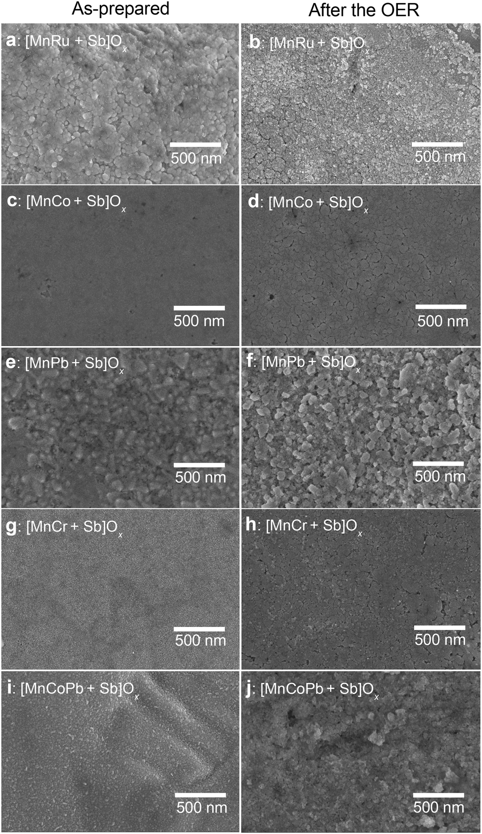 | ||
| Fig. 1 Scanning electron micrographs of the (a and b) [MnRu + Sb]Ox, (c and d) [MnCo + Sb]Ox, (e and f) [MnPb + Sb]Ox, (g and h) [MnCr + Sb]Ox and (i and j) [MnPbCo + Sb]Ox catalysts (a, c, e, g and i) before and (b, d, f, h and j) after 24 h galvanostatic (at 10 mA cm−2geom.) and subsequent 1 h potentiostatic (at 2.03 and 1.93 V vs. RHE for 0.5 h at each potential) operation in stirred 0.5 M H2SO4 at 24 ± 2 °C. | ||
The initial composition of the examined water oxidation electrocatalysts included 1 μmol cm−2 Sb mixed with 1 μmol cm−2 of metals. For the major manganese-containing samples, the metal ratios were Mn:M = 0.67:0.33 for M = Co, Pb or Cr, Mn:Co:Pb = 0.50:0.25:0.25 and Mn:Ru = 0.95:0.05. Relatively low total metal loading of 1 μmol cm−2 (hereinafter, per geometric surface area of the electrode) was used to provide a fair assessment of the activity and stability. However, this low loading precluded any meaningful analysis of the materials by X-ray diffraction.
During operation, the catalyst layer composition changed due to the corrosion, which was evident from the partial roughing of the surface as visualised by SEM (Fig. 1) and quantified spectroscopically, as discussed later in the text. Importantly, the homogeneity of the distribution of elements within the catalyst layers was not affected by the OER (Fig. S1, ESI†). We also note that such corrosion is unavoidable for essentially any known OER catalyst, even iridium-based, when operated in low-pH electrolyte solutions, especially at elevated temperatures.4 At the same time, as demonstrated in recent studies by Cherevko and colleagues, catalyst stability under actual PEM water electrolyser anode conditions are significantly less damaging,40,41 meaning that a catalytic material demonstrating acceptable stability in a solution with dissolved electrolyte like H2SO4 is likely to be sufficiently robust for the target application.
Spectroscopic characterisation
X-ray photoelectron spectroscopic (XPS) analysis of the catalysts before and after (vide infra) electrocatalytic tests confirmed that antimony always adopts a ∼5+ oxidation state in all multimetallic antimony oxide catalysts studied herein (Fig. S2a–e, ESI†), which is consistent with previous reports.24,25 The major signal in the Mn 2p spectra was also similar for all freshly prepared and tested manganese–metal–antimony materials and consistent with the Mn3+ oxide/oxyhydroxide type species (Fig. S3, ESI†), although it is well-understood that unambiguous discrimination between the transition metal states based on their 2p spectra is hardly possible. Nevertheless, it was noted that introduction of Pb, Cr and Ru to [Mn + Sb]Ox increased the relative intensity of the Mn 2p shake-up signal at ca 646–647 eV, which might be indicative of the higher contribution of Mn2+.42 This effect was most pronounced for the Pb-containing catalysts [MnPb + Sb]Ox and [MnCoPb + Sb]Ox (Fig. S3b and c, ESI†).The major peaks in the Pb 4f spectra of [MnPb + Sb]Ox and [MnCoPb + Sb]Ox were inconsistent with PbO2 and PbO, but were positioned at the binding energies typical of inorganic Pb2+ salts like lead(II) titanate43 (Fig. S4, ESI†). Co 2p spectra for [MnCo + Sb]Ox and [MnCoPb + Sb]Ox (Fig. S5, ESI†) and Cr 2p data for [MnCr + Sb]Ox (Fig. S6, ESI†) suggest the 3+ metal oxidation states, though the interpretations are complicated by low signal-to-noise ratio. Small amounts of ruthenium (5 at% of the overall Mn + Ru content) introduced into [MnRu + Sb]Ox could not be detected on the surface of the as-prepared catalysts, but low-intensity signals that could be attributed to a Ru3++ Ru4+ combination44 emerged after the OER tests (Fig. S2i, ESI†).
To gain deeper insights into the structural features of the multimetallic antimonate catalysts, X-ray absorption spectroscopic (XAS) analysis was undertaken at the Mn K, Co K, Pb L3 and Sb K-edges. Analysis of the bulk state of the catalysts by XAS indicated that the predominant antimony state in [MnCo + Sb]Ox and [MnCoPb + Sb]Ox appears consistent with a 5+ oxidation state within a disordered oxide compound (Fig. S7a, ESI†). Shifts of the Sb K-edge X-ray absorption near edge structure (XANES) spectra to higher energies induced by the OER tests suggest slight oxidation of antimony (Fig. S7b, ESI†), but there were very limited changes to the extended X-ray absorption fine structure (EXAFS) indicating the redox event was delocalised over many antimony atoms (Fig. S7c and d, ESI†). Overall, the Sb K-edge XAS data for the multimetallic samples were similar to those for the monometallic [Mn + Sb]Ox and [Co + Sb]Ox reference materials.24 Considering minimal effects of secondary metals on the state of antimony for [MnCo + Sb]Ox and [MnCoPb + Sb]Ox, and close similarity of the Sb 3d spectra for all examined catalysts (Fig. S2a–e, ESI†), we did not explore the Sb K-edges of other materials.
XAS analysis at the metal edges revealed some differences from their surface states, which did not undergo notable changes after the OER as discussed above. The Mn K-edge XANES of as-prepared [MnCo + Sb]Ox, [MnPb + Sb]Ox and [MnCoPb + Sb]Ox differed marginally between each material and all indicated an oxidation state between 2+ and 3+ (Fig. 2a). The OER testing induced an increase in the oxidation state of Mn and produced more consistent Mn K-edge XANES data between materials, which were now resembling that found for the tested [Mn + Sb]Ox reference sample (Fig. 2b). EXAFS data corroborate these observations and indicate that the initial differences are likely associated with the presence of different amounts of individual manganese oxides, like Mn2O3 (Fig. 2c–e). The presence of such admixtures in the as-synthesised [Mn + Sb]Ox electrodes and their relatively rapid corrosion during the OER was reported in our previous work, which used the same strategy to prepare the materials.24 Consistent with these previous interpretations, the Mn2O3 admixtures were removed after the OER producing closely-matching Mn K-edge EXAFS spectra for the [Mn + Sb]Ox reference and the catalysts with introduced secondary metals examined herein (Fig. 2c–e). This indicates that a structurally similar state of manganese is established in these materials after operation as water electrooxidation catalysts.
 | ||
| Fig. 2 Mn K-edge (a and b) XANES, (c) EXAFS and (d and e) FT EXAFS data collected for the [Mn + Sb]Ox (orange), [MnCo + Sb]Ox (red), [MnPb + Sb]Ox (blue) and [MnCoPb + Sb]Ox (green) catalysts before and after OER tests (10 mA cm−2, 24 h, 24 ± 2 °C) compared to relevant reference materials (see figure). In panel c, dashed and solid traces show data collected before and after the OER tests, respectively. | ||
In our previous study, we suggested that [Mn + Sb]Ox might contain a mix of manganese oxides and possibly a disordered manganese antimonate type structure.24 However, our updated analysis of the new data presented herein, some of which are of improved resolution, suggests that the dominating state of Mn in [Mn + Sb]Ox resembles that in MnOOH (Fig. 2c and e), very similar to a protonated form of birnessite or layer-like polymorph of manganite or feitknechtite. While Mn(III)–O–Mn(III) structural motifs typically disproportionate leading to dissolution when formed, this undesirable process is strongly suppressed by the stabilising effect of the antimony oxide matrix. Thus, we suggest that [Mn + Sb]Ox majorly contains the disordered MnIIIOOH-type material intimately intermixed with Sb5+ oxides (Fig. S1, ESI†), which imparts the resulting nanocomposite with enhanced activity and stability during the OER in acidic electrolyte solutions.24
For the Co-containing samples, trends in the Co K-edge XANES and EXAFS data indicate that the OER testing removes the initially present Co3O4 admixture while increasing the oxidation state of cobalt closer to 3+; this is apparent by the XANES shifting to higher energy with the loss of the tetrahedral Co2+ site of Co3O4 (Fig. S8a and b, ESI†). Corresponding Co K-edge EXAFS was very similar to that of the tested [Co + Sb]Ox control sample, which adopts an antimonate phase24 (Fig. S8c and d, ESI†). It is also noted that the Mn and Co K-edge EXAFS within the same sample were dissimilar, indicating that the two metals do not occupy the same sites in the oxide structure.
Notable differences were also observed in the Pb L3-edge XAS for the lead-containing catalysts (Fig. S9, ESI†). While the as-prepared [MnPb + Sb]Ox and [MnCoPb + Sb]Ox exhibit similar XANES corresponding to the Pb oxidation state below 4+ (Fig. S9a, ESI†), the EXAFS data are distinctly different from each other (Fig. S9c, ESI†). Considering the lack of similarity between the EXAFS features at the Pb L3, Mn K and Sb K-edges, it is unlikely that lead is doped into manganese or antimony oxides, but is probably present as a separate oxide species. Most importantly, the OER testing results in complete transformation of lead species into PbO2 for [MnCoPb + Sb]Ox, as well as in partial oxidation of the Pb component closer to the 4+ state in [MnPb + Sb]Ox (Fig. S9b, ESI†). These observations support our interpretation of the presence of lead as a separate phase, which is intimately intermixed with manganese and antimony oxides to produce a nanocomposite (Fig. S1b, ESI†).
Overall, ex situ spectroscopic characterisation confirmed that modification of the [Mn + Sb]Ox catalyst with secondary metals did not notably affect the antimony-oxide matrix component, as well as the bulk state of the catalytically active manganese. While some differences were observed in the as-prepared materials, the more relevant Mn K-edge XAS data collected for the tested catalysts indicate that they share a major structurally similar MnOOH-type motif (Fig. 2c and e). No indications of doping of the secondary metals into the Mn or Sb oxides were found, indicating that all catalysts investigated herein are predominantly nanocomposites. At the same time, differences were found in the surface, i.e. most important from the catalytic perspective, manganese states, especially for the catalysts containing lead (Fig. S3, ESI†). As discussed below, these changes affected the performance of the catalysts during the OER.
Electrocatalytic performance
Catalytic activity of the examined electrocatalysts is majorly discussed below in terms of the (quasi)stabilised OER overpotential required to achieve the current density of 10 mA cm−2 (hereinafter all currents are normalised to the geometric surface area of the electrodes), which is a convenient and reasonable approach considering the essentially flat morphology of the tested electrodes (Fig. 1). The IRu-corrected OER overpotential established after 24 h galvanostatic tests at 10 mA cm−2 for the [Mn + Sb]Ox benchmark was 0.680 ± 0.010 V at 24 ± 2 °C, while all multimetallic OER catalysts examined herein reproducibly demonstrated higher activity (Fig. 3a–c and Fig. S10–S14, ESI†). It is useful to note that 10 mA cm−2 under conditions employed herein corresponds to a highly respectable OER current density of ca 180 A g−1 per unit mass of the catalytically active manganese for [Mn + Sb]Ox. Additional chronoamperometric tests at 2.03 and 1.93 V vs. RHE were undertaken to confirm that the performance was stabilised on the timescale of our experiments, which is often easy to overlook in the chronopotentiometric regime, as well as to demonstrate operation at elevated mass-normalised OER rates. | ||
| Fig. 3 Electrocatalytic OER performance of the [MnRu + Sb]Ox (black), [MnPb + Sb]Ox (blue), [MnCoPb + Sb]Ox (green), [MnCr + Sb]Ox (brown), [MnCo + Sb]Ox (red), and [Mn + Sb]Ox (orange) catalysts in stirred 0.5 M H2SO4 at (a–c) 24 ± 2 and (d–f) 60 ± 1 °C: (a and d) cyclic voltammetry (scan rate 0.020 V s−1; not IRu-corrected), (b and e) IRu-corrected chronopotentiograms at 10 mA cm−2geom., and (c and f) chronoamperograms at 2.03 and 1.93 V vs. RHE (not IRu-corrected). Currents are normalised to the geometric surface area (0.25 cm2). In panels c and f, Ru values for each experiment are provided in the brackets; corresponding IRu products (V) calculated using the quasi-stabilised currents at 2.03 & 1.93 V vs. RHE were: (c) [MnRu + Sb]Ox – 0.25 & 0.15, [MnPb + Sb]Ox – 0.19 & 0.10, [MnCr + Sb]Ox – 0.16 & 0.05, [MnCoPb + Sb]Ox – 0.13 & 0.06, [MnCo + Sb]Ox – 0.13 & 0.06, [Mn + Sb]Ox – 0.06 & 0.05; (f) [MnPb + Sb]Ox – 0.20 & 0.12, [MnCoPb + Sb]Ox – 0.17 & 0.09, [MnCo + Sb]Ox – 0.18 & 0.06, [Mn + Sb]Ox – 0.09 & 0.04, respectively. | ||
Initially recorded voltammograms for all materials examined did not undergo significant changes with cycling except for the minor improvements in the oxidative currents for some of the catalysts, which is an important indication of their satisfactory initial stability (Fig. S15, ESI†). The amount of charge passed during the subsequent 24 h chronopotentiometric tests at 10 mA cm−2 was 216 C, while the maximal theoretical charge required to oxidise metals present on the electrode surface does not exceed 0.1 C (assuming a hypothetical 4e− oxidation of Mn3+); hence, the measured currents can be only sustained by the OER.
These results demonstrate that [MnRu + Sb]Ox is able to sustain activity for the OER that is significantly higher than that of the [Mn + Sb]Ox reference upon introduction of a very low amount of ruthenium. Importantly, Ru was detectable by XPS on the catalyst surface after the OER tests (Fig. S2i, ESI†) and its corrosion in to the electrolyte solution after 24 h of operation at 10 mA cm−2 was below the detection limit of the ICP-OES analysis (Table S2, ESI†). At the same time, the loss of Mn was detected, and might be ascribed to the observed decrease in the activity. In other words, the enhanced OER activity of [MnRu + Sb]Ox is likely provided by both ruthenium- and manganese-based active sites.
The stabilised performance of the [MnRu + Sb]Ox catalyst after 24 h at 10 mA cm−2 and 24 ± 2 °C is incomparably better than that of the antimony-free reference materials prepared under the same conditions, i.e. MnOx and RuO2 (ηIR ≈ 0.8 V for both), the latter almost completely dissolving within only 1 h of operation.24 These comparisons confirm that a strong stabilising effect of SbOx is maintained in the bimetallic system. Moreover, IrO2 benchmark prepared using the same method at 1 μmolIr cm−2 loading requires ηIR ≈ 0.45 V to sustain the OER rate of 10 mA cm−2 after 24 h and continuously loses its activity (ca 0.002–0.003 V h−1),24 which is comparable to the performance of [MnRu + Sb]Ox initially containing only 0.05 μmolRu cm−2 of a more readily available ruthenium.
:Co = 2:1 (Fig. S18, ESI†). Examination of the voltammetric (Fig. S16, ESI†) and XPS data (Table S1, ESI†) revealed only a slight increase in the surface concentration of the electrochemically active transition metal species upon introduction of Co, which might be partially responsible for the increase in the activity, although one might not exclude a synergistic catalytic effect of combining Mn and Co within a SbOx matrix. When operated over 24 h at a constant current density of 10 mA cm−2, [MnCo + Sb]Ox lost some of its initial activity due to partial corrosion of all elements (Table S2, ESI†) and concomitant decrease in the relative surface concentration of Mn (Table S1, ESI†). However, in contrast to [MnCr + Sb]Ox, the Mn–Co-based catalyst reproducibly achieved stabilised performance after approximately 12 h of operation at 10 mA cm−2 (Fig. S11, ESI†) with ηIR = 0.640 ± 0.010 V, which is 0.040 ± 0.014 V better than that for the manganese–antimony oxide reference.
Consistent with the XAS data (Fig. S9, ESI†), voltammetric analysis indicated an increase in the amount of electroactive lead(IV) species on the electrode surface during the OER, as concluded from the enhanced Pb4+/2+ process in voltammetry (Fig. S16c and e, ESI†). Importantly, both PbOy and [Pb + Sb]Ox are not highly active OER catalysts under the examined conditions (Fig. S17, ESI†) and no enrichment of the catalyst surfaces with Mn was found for [MnPb + Sb]Ox and [MnCoPb + Sb]Ox (Table S1, ESI†). These observations indicate a promoting effect of lead on the catalytic performance of the manganese-based active species. Most likely, this is associated with the capacity of PbO2 detected by voltammetry (Fig. S16c and e, ESI†) and XAS (Fig. S9, ESI†) to stabilise catalytically active transition metal species,12,14viz. manganese and cobalt in the present case (Tables S1 and S2, ESI†).
Consistent with the instability observed at 24 ± 2 °C, [MnCr + Sb]Ox suffered rapid corrosion at 60 ± 1 °C eventuating in complete degradation after ca 6 h (Fig. S19, ESI†). Other catalysts were much more stable, but, quite unexpectedly, a positive effect of increased temperature on the OER kinetics was not observed in the initial voltammetric tests, while [Mn + Sb]Ox enabled higher OER rates at 60 ± 1 °C as compared to ambient temperature (Fig. 3d and Fig. S20 and S21, ESI†). However, much more relevant galvanostatic tests revealed that the most stable [MnPb + Sb]Ox and [MnPbCo + Sb]Ox materials improve in activity during the initial hours of operation at 60 ± 1 °C, eventually demonstrating the quasi-stabilised OER activity at 10 mA cm−2 better than [Mn + Sb]Ox by ca 0.05 and 0.03 V, respectively (Fig. 3e). This improvement is also reflected in cyclic voltammograms recorded after the tests (Fig. S22, ESI†). Contrasting this behaviour, both [Mn + Sb]Ox and [MnCo + Sb]Ox notably degraded after operation for 24 h at 60 ± 1 °C, further highlighting the combined stabilisation effect of the lead and antimony oxide components. It is also noteworthy that the [MnPb + Sb]Ox catalyst was able to achieve operation at a mass-normalised OER rate of as high as ca 2100 A gMn−1 in the potentiostatic regime (ca 58 mA cm−2 at 2.03 V vs. RHE with 0.5 μmolMn cm−2 loading; Fig. 3f). Such high current densities are typically reported for the PEM water electrolyser anode conditions, which are more favourable than liquid 0.5 M H2SO4 aqueous electrolyte40,41 employed herein.
Summary of the effects of secondary metals on the OER performance of manganese–antimony oxide catalysts
Fig. 4 summarises the OER performance in 0.5 M H2SO4 of the multimetallic manganese–antimony oxide catalysts compared to that of [Mn + Sb]Ox. | ||
| Fig. 4 Summary of the effects of different promotors on the overpotential required to sustain of the OER rate of 10 mA cm−2 by manganese–antimony oxide catalysts in stirred 0.5 M H2SO4 over the first 5 minutes (left) and at the end (right) of the galvanostatic tests at (a) 24 ± 2 and (b) 60 ± 1 °C. Data are presented either as mean ± one standard deviation for tests of more than three independent electrodes or as individual data points where one or two tests were done. Data are colour coded as follows: [Mn + Sb]Ox – orange; [MnCoPb + Sb]Ox – green; [MnCo + Sb]Ox – red; [MnPb + Sb]Ox – blue; [MnCr + Sb]Ox – brown, and [MnRu + Sb]Ox – black. Horizontal orange lines show the initial performance of [Mn + Sb]Ox. | ||
The first conclusion from these data is that the introduction of all secondary metals examined immediately improves the catalytic activity of the Mn–Sb oxide at 24 ± 2 °C, while the promoting effect at higher temperatures requires some period of activation achieved by operation at 10 mA cm−2. The promoting effect of Cr is likely associated with the increased surface concentration of Mn-based species, which also results in the weakest operational stability of this type of catalysts.
Introduction of Co produces more stable materials but weaker enhancement in the activity, which was also slowly deteriorating during tests at 10 mA cm−2. The most promising results were obtained for the [MnPb + Sb]Ox, which was not only significantly more active than [Mn + Sb]Ox but also maintained stability in operation. The improvement is likely associated with the presence of Pb4+ oxide intermixed with the Mn and Sb oxide species. Simultaneous introduction of Pb and Co did not provide any notable advantages as compared to [MnPb + Sb]Ox, though still produced better performing catalysts than the monometallic [Mn + Sb]Ox system.
The second conclusion from the presented data is that operation at higher temperature induces losses in the catalytically active sites from the multimetallic materials, which is not unexpected. Most importantly, the [MnPb + Sb]Ox catalytic system provided higher stability than [Mn + Sb]Ox at 60 ± 1 °C and performed notably better after 24 h of tests (Fig. 4b).
Stabilising effects of Sb and Pb oxides
To explore the origins of the stabilising effects of lead and antimony oxides on the catalytically active Mn-based species, we have undertaken an in situ Mn K-edge XAS analysis of three key materials Mn2O3, [Mn + Sb]Ox and [MnPb + Sb]Ox during the OER in 0.5 M H2SO4 at ambient temperature. Meaningful in situ spectroelectrochemical analysis required deposition of the catalysts in the form of highly-dispersed particles on the surface of the carbon fibre working electrode, which has proven to enable the collection of high-quality in situ XAS data.18 Our attempts to detach the highly robust catalyst layers from the FTO surface did not produce materials of the required quality. This urged us to apply an ethylene glycol polyol reduction method,47,48 which was adapted herein for the synthesis of [Mn + Sb]Ox and [MnPb + Sb]Ox.Transmission electron microscopic analysis showed that the resulting materials represent aggregates of particles of variable size (Fig. S23a–c, ESI†). The X-ray diffraction pattern of the Mn2O3 sample was consistent with the tabulated data, while that of the as-synthesised [Mn + Sb]Ox powder agreed well with the reported results for the FTO-supported sample of this composition24 (Fig. S23d, ESI†). Comparisons of the ex situ XAS data collected for the as-synthesised FTO-supported [Mn + Sb]Ox films and freestanding powders also confirmed that these materials are structurally very similar (Fig. S24a–c, ESI†). In the case of [MnPb + Sb]Ox, the as-synthesised powder material presented a mix of phases, as expected for a nanocomposite (Fig. S23d, ESI†), and was dominated by Mn species with higher oxidation states than in the FTO-supported materials (Fig. S24d–f, ESI†). We interpret the latter observation in terms of the lower contribution of the Mn2O3 and other MnOx admixtures provided by the polyol-based method.
First, we examined the behaviour of the monometallic Mn2O3 reference material. Application of 1.80 V vs. RHE to Mn2O3 induced notable increase in the oxidation state of manganese above 3+, although a more positive potential of 2.00 V vs. RHE did not produce further notable changes in the XAS data (Fig. 5a and Fig. S25a and b, ESI†). Interestingly, subsequent analysis at 1.80 V vs. RHE produced XANES spectra suggesting lower oxidation state of Mn as compared to the initial data set recorded at the same potential (Fig. 5a). Collection of meaningful data at potentials more positive than 2.00 V vs. RHE was essentially impossible due to a rapid loss of signal, while the signal-to-noise ratio of the XAS during the analysis at 1.80 and 2.00 V vs. RHE was progressively decreasing during measurements. We attribute these observations to the continuous dissolution of manganese into the electrolyte solution, resulting in the formation of species with lower oxidation state(s) than those within MnOx solids remaining in direct contact with the electrode. Thus, in situ XAS confirms that continuous dissolution of Mn2O3 during the OER in 0.5 M H2SO4 is promoted by the electrooxidation of manganese.
 | ||
| Fig. 5 Mn K-edge XANES spectra of (a) Mn2O3, (b) [Mn + Sb]Ox and (c) [MnPb + Sb]Ox collected ex situ (grey) and in situ in contact with 0.5 M H2SO4 aqueous solutions at 1.80 (green), 1.95 (blue), 2.05 (orange) and 2.15 V vs. RHE (wine) at 24 ± 2 °C. Dashed and dashed-dotted lines show reference data for Mn2O3 and MnOOH powders, respectively. For Mn2O3, green and light green data were collected at the same potential of 1.8 V vs. RHE before and after analysis at 2.00 V vs. RHE. | ||
Changes in the in situ Mn K-edge XANES spectra of [Mn + Sb]Ox were significantly less pronounced than those found for Mn2O3 and demonstrated only slight oxidation upon application of the progressively positive potentials of 1.80, 1.95 and 2.05 V vs. RHE (Fig. 5b). Examination of the EXAFS data suggests that the initially present Mn2O3 species are significantly depleted within the [Mn + Sb]Ox catalyst already at 1.8 V vs. RHE, and that MnOOH becomes a predominant structural motif at more positive potentials (Fig. S25c and d, ESI†). While the collection of meaningful in situ Mn K-edge XAS for [Mn + Sb]Ox was possible even at 2.15 V vs. RHE, it was found that application of this very positive potential induced notable oxidation of manganese. This is expected to result in slow corrosion and loss in activity, which was discussed above (Fig. 4).
Contrasting this behaviour, the [MnPb + Sb]Ox material demonstrated only minimal changes in the Mn K-edge XAS (Fig. 5c and Fig. S25e and f, ESI†) at all potentials examined, including the extremely positive 2.15 V vs. RHE. The lack of any changes to the Mn oxidation state indicates the high stability of the catalytically active sites, which we attribute to the stabilising effect of lead oxides discussed above. We also hypothesise that the higher activity of [MnPb + Sb]Ox compared to [Mn + Sb]Ox is majorly associated with the improved stability of the Mn-based catalytic species, which are not rapidly lost upon contact with corrosive 0.5 M H2SO4 and application of positive potentials.
Overall, in situ XAS analysis suggests that antimony and lead oxides prevent notable changes in the oxidation state and structure of the catalytically active manganese sites under the OER conditions in 0.5 M H2SO4, and that the combination of the two stabilising matrices induces further notable improvements to the performance and stability.
Conclusions
The present study demonstrates that significant improvements in the performance of the promising Mn–Sb mixed oxide acidic water oxidation catalysts are possible through the modification with secondary metals. The introduction of lead and small amounts of ruthenium produces the highest activity catalysts. The ability of Pb to further stabilise manganese active sites within the antimonate matrix is a key important finding of both fundamental and applied significance. This stabilising effect supports the improved OER performance of the manganese-lead-antimony oxide system. Importantly, [MnPb + Sb]Ox provides one of the highest catalytic activities for the OER in acidic electrolyte solutions reported to date, among Ru/Ir-free catalysts demonstrating reasonable stability in operation, especially at elevated temperatures (Table S3, ESI†).Future work building upon these results, in particular investigating the effects of composition, synthesis conditions and morphology on the performance, might eventuate in the design of new, more stable earth-abundant OER catalysts operating at low pH and elevated temperatures for PEM water electrolysers. In particular, this can be achieved through the further improvements and optimisation of the synthesis and composition of the highly-dispersed [MnPb + Sb]Ox catalyst.
Author contributions
SL and MC designed and carried out synthesis and electrochemical experiments, analysed data and co-wrote the manuscript; DS synthesised materials, undertook electrochemical experiments and analysed data; DS, KND and BVK carried out ex situ and in situ XAS studies and analysed XAS data; TDN undertook microscopic analysis; GY developed and undertook the synthesis of dispersed catalysts; BJ assisted with the XAS studies; DRM interpreted data and co-wrote the manuscript; AY supervised part of the study undertaken at IITB and contributed to data interpretation; RKH supervised characterisation studies and interpreted data; ANS conceived of and supervised the project, analysed and interpreted data, and co-wrote the manuscript.Conflicts of interest
There are no conflicts to declare.Acknowledgements
Some parts of this work were undertaken at the XAS beamline of the Australian Synchrotron, Monash X-ray Platform and Monash Centre for Electron Microscopy. The authors also acknowledge Indian National Centre for Photovoltaic Research and Education (NCPRE), and Sophisticated Analytical Instrument Facility (SAIF) for providing access to their facilities. This study was financially supported by the Australian Research Council (Future Fellowship to ANS; FT200100317), Australian Renewable Energy Agency (contract No. 2018/RND008), MNRE Government of India (NCPRE-Phase II, IIT Bombay to AY), Early Career Research Award, Science and Engineering Research Board, Government of India (ECR/2016/000550 to AY), and IITB-Monash Academy (PhD scholarship to SL).Notes and references
- K. Ayers, N. Danilovic, R. Ouimet, M. Carmo, B. Pivovar and M. Bornstein, Annu. Rev. Chem. Biomol. Eng., 2019, 10, 219–239 CrossRef CAS PubMed.
- T. Reier, H. N. Nong, D. Teschner, R. Schlögl and P. Strasser, Adv. Energy Mater., 2017, 7, 1601275 CrossRef.
- D. R. MacFarlane, J. Choi, B. H. R. Suryanto, R. Jalili, M. Chatti, L. M. Azofra and A. N. Simonov, Adv. Mater., 2020, 32, 1904804 CrossRef CAS PubMed.
- S. Geiger, O. Kasian, M. Ledendecker, E. Pizzutilo, A. M. Mingers, W. T. Fu, O. Diaz-Morales, Z. Li, T. Oellers, L. Fruchter, A. Ludwig, K. J. J. Mayrhofer, M. T. M. Koper and S. Cherevko, Nat. Catal., 2018, 1, 508–515 CrossRef CAS.
- J. Kibsgaard and I. Chorkendorff, Nat. Energy, 2019, 4, 430–433 CrossRef.
- L. Li, P. Wang, Q. Shao and X. Huang, Adv. Mater., 2021, 33, 2004243 CrossRef CAS PubMed.
- J. Kim, P.-C. Shih, K.-C. Tsao, Y.-T. Pan, X. Yin, C.-J. Sun and H. Yang, J. Am. Chem. Soc., 2017, 139, 12076–12083 CrossRef CAS PubMed.
- Z. Shi, X. Wang, J. Ge, C. Liu and W. Xing, Nanoscale, 2020, 12, 13249–13275 RSC.
- M. Wiechen, M. M. Najafpour, S. I. Allakhverdiev and L. Spiccia, Energy Environ. Sci., 2014, 7, 2203–2212 RSC.
- N. Menzel, E. Ortel, K. Mette, R. Kraehnert and P. Strasser, ACS Catal., 2013, 3, 1324–1333 CrossRef CAS.
- D. Simondson, M. Chatti, S. A. Bonke, M. F. Tesch, R. Golnak, J. Xiao, D. A. Hoogeveen, P. V. Cherepanov, J. L. Gardiner, A. Tricoli, D. R. MacFarlane and A. N. Simonov, Angew. Chem., Int. Ed., 2021, 60, 15821–15826 CrossRef CAS PubMed.
- M. Chatti, J. L. Gardiner, M. Fournier, B. Johannessen, T. Williams, T. R. Gengenbach, N. Pai, C. Nguyen, D. R. MacFarlane, R. K. Hocking and A. N. Simonov, Nat. Catal., 2019, 2, 457–465 CrossRef CAS.
- M. Mohammadi, F. Mohammadi and A. Alfantazi, J. Electrochem. Soc., 2013, 160, E35–E43 CrossRef CAS.
- X. Li, D. Pletcher and F. C. Walsh, Chem. Soc. Rev., 2011, 40, 3879–3894 RSC.
- H.-L. Du, M. Chatti, B. Kerr, C. K. Nguyen, T. Tran-Phu, D. A. Hoogeveen, P. V. Cherepanov, A. S. R. Chesman, B. Johannessen, A. Tricoli, R. K. Hocking, D. R. MacFarlane and A. N. Simonov, ChemCatChem, 2022, 14, e202200013 CAS.
- S. Manabe, C. M. Wong and C. S. Sevov, J. Am. Chem. Soc., 2020, 142, 3024–3031 CrossRef CAS PubMed.
- P.-Y. Olu, E. Yokomizo and T. Kinumoto, ACS Appl. Energy Mater., 2022, 5, 11450–11461 CrossRef CAS.
- D. Simondson, M. Chatti, J. L. Gardiner, B. V. Kerr, D. A. Hoogeveen, P. V. Cherepanov, I. C. Kuschnerus, T. D. Nguyen, B. Johannessen, S. L. Y. Chang, D. R. MacFarlane, R. K. Hocking and A. N. Simonov, ACS Catal., 2022, 12, 12912–12926 CrossRef CAS.
- L. Moriau, M. Smiljanić, A. Lončar and N. Hodnik, ChemCatChem, 2022, 14, e202200586 CrossRef CAS PubMed.
- M. E. Kreider, G. T. K. K. Gunasooriya, Y. Liu, J. A. Zamora Zeledón, E. Valle, C. Zhou, J. H. Montoya, A. Gallo, R. Sinclair, J. K. Nørskov, M. B. Stevens and T. F. Jaramillo, ACS Catal., 2022, 12, 10826–10840 CrossRef CAS.
- A. Shinde, R. J. R. Jones, D. Guevarra, S. Mitrovic, N. Becerra-Stasiewicz, J. A. Haber, J. Jin and J. M. Gregoire, Electrocatalysis, 2015, 6, 229–236 CrossRef CAS.
- L. Zhou, A. Shinde, J. H. Montoya, A. Singh, S. Gul, J. Yano, Y. Ye, E. J. Crumlin, M. H. Richter, J. K. Cooper, H. S. Stein, J. A. Haber, K. A. Persson and J. M. Gregoire, ACS Catal., 2018, 8, 10938–10948 CrossRef CAS.
- T. A. Evans and K.-S. Choi, ACS Appl. Energy Mater., 2020, 3, 5563–5571 CrossRef CAS.
- S. Luke, M. Chatti, A. Yadav, B. V. Kerr, J. Kangsabanik, T. Williams, P. V. Cherepanov, B. Johannessen, A. Tanksale, D. R. MacFarlane, R. K. Hocking, A. Alam, A. Yella and A. N. Simonov, J. Mater. Chem. A, 2021, 9, 27468–27484 RSC.
- I. A. Moreno-Hernandez, C. A. MacFarland, C. G. Read, K. M. Papadantonakis, B. S. Brunschwig and N. S. Lewis, Energy Environ. Sci., 2017, 10, 2103–2108 RSC.
- J. S. Mondschein, J. F. Callejas, C. G. Read, J. Y. C. Chen, C. F. Holder, C. K. Badding and R. E. Schaak, Chem. Mater., 2017, 29, 950–957 CrossRef CAS.
- J. Yang, Q. Shao, B. Huang, M. Sun and X. Huang, iScience, 2019, 11, 492–504 CrossRef CAS PubMed.
- S. Laha, Y. Lee, F. Podjaski, D. Weber, V. Duppel, L. M. Schoop, F. Pielnhofer, C. Scheurer, K. Müller, U. Starke, K. Reuter and B. V. Lotsch, Adv. Energy Mater., 2019, 9, 1803795 CrossRef.
- S. A. Bonke, K. L. Abel, D. A. Hoogeveen, M. Chatti, T. Gengenbach, M. Fournier, L. Spiccia and A. N. Simonov, ChemPlusChem, 2018, 83, 704–710 CrossRef CAS PubMed.
- B. Chen, S. Wang, J. Liu, H. Huang, C. Dong, Y. He, W. Yan, Z. Guo, R. Xu and H. Yang, Corros. Sci., 2018, 144, 136–144 CrossRef CAS.
- Y. Lin, Z. Tian, L. Zhang, J. Ma, Z. Jiang, B. J. Deibert, R. Ge and L. Chen, Nat. Commun., 2019, 10, 162 CrossRef PubMed.
- X. Gu, J. Yue, L. Li, H. Xue, J. Yang and X. Zhao, Electrochim. Acta, 2015, 184, 250–256 CrossRef CAS.
- R. L. LeRoy, C. T. Bowen and D. J. LeRoy, J. Electrochem. Soc., 1980, 127, 1954 CrossRef CAS.
- H. J. King, M. Fournier, S. A. Bonke, E. Seeman, M. Chatti, A. N. Jumabekov, B. Johannessen, P. Kappen, A. N. Simonov and R. K. Hocking, J. Phys. Chem. C, 2019, 123, 28533–28549 CrossRef CAS.
- P. Kappen and G. Ruben, Australian Synchrotron, 2013.
- B. Ravel and M. Newville, J. Synchrotron Radiat., 2005, 12, 537–541 CrossRef CAS PubMed.
- A. Tenderholt, B. Hedman and K. O. Hodgson, AIP Conf. Proc., 2007, 882, 105–107 CrossRef CAS.
- J. Goulon, C. Goulon-Ginet, R. Cortes and J. M. Dubois, J. Phys., 1982, 43, 539–548 CrossRef CAS.
- L. Tröger, D. Arvanitis, K. Baberschke, H. Michaelis, U. Grimm and E. Zschech, Phys. Rev. B: Condens. Matter Mater. Phys., 1992, 46, 3283–3289 CrossRef PubMed.
- J. Knöppel, M. Möckl, D. Escalera-López, K. Stojanovski, M. Bierling, T. Böhm, S. Thiele, M. Rzepka and S. Cherevko, Nat. Commun., 2021, 12, 2231 CrossRef PubMed.
- K. Ehelebe, D. Escalera-López and S. Cherevko, Curr. Opin. Electrochem., 2021, 29, 100832 CrossRef CAS.
- M. C. Biesinger, B. P. Payne, A. P. Grosvenor, L. W. M. Lau, A. R. Gerson and R. S. C. Smart, Appl. Surf. Sci., 2011, 257, 2717–2730 CrossRef CAS.
- I. Szafraniak, M. Połomska, B. Hilczer, E. Talik and L. Kepiński, Ferroelectrics, 2006, 336, 279–287 CrossRef CAS.
- D. J. Morgan, Surf. Interface Anal., 2015, 47, 1072–1079 CrossRef CAS.
- C.-C. Lin and C. C. L. McCrory, ACS Catal., 2017, 7, 443–451 CrossRef CAS.
- W. Gou, M. Zhang, Y. Zou, X. Zhou and Y. Qu, ChemCatChem, 2019, 11, 6008–6014 CrossRef CAS.
- D. González-Quijano, W. J. Pech-Rodríguez, J. I. Escalante-García, G. Vargas-Gutiérrez and F. J. Rodríguez-Varela, Int. J. Hydrogen Energy, 2014, 39, 16676–16685 CrossRef.
- J. Quinson, M. Inaba, S. Neumann, A. A. Swane, J. Bucher, S. B. Simonsen, L. Theil Kuhn, J. J. K. Kirkensgaard, K. M. Ø. Jensen, M. Oezaslan, S. Kunz and M. Arenz, ACS Catal., 2018, 8, 6627–6635 CrossRef CAS.
Footnotes |
| † Electronic supplementary information (ESI) available. See DOI: https://doi.org/10.1039/d3ey00046j |
| ‡ These authors contributed equally to this work. |
| This journal is © The Royal Society of Chemistry 2023 |