A redox-mediated zinc electrode for ultra-robust deep-cycle redox flow batteries†
Shiqiang
Huang
a,
Zhizhang
Yuan
 c,
Manohar
Salla
a,
Xun
Wang
a,
Hang
Zhang
 a,
Songpeng
Huang
a,
Dao Gen
Lek
a,
Xianfeng
Li
a,
Songpeng
Huang
a,
Dao Gen
Lek
a,
Xianfeng
Li
 *c and
Qing
Wang
 *ab
*ab
aDepartment of Materials Science and Engineering, National University of Singapore, Singapore 117575, Singapore. E-mail: msewq@nus.edu.sg
bInstitute of Materials Research and Engineering (IMRE), Agency for Science Technology and Research (A*STAR), Singapore, 138632, Singapore
cDivision of Energy Storage, Dalian National Laboratory for Clean Energy, Dalian Institute of Chemical Physics, Chinese Academy of Sciences, Zhongshan Road 457, Dalian 116023, China. E-mail: lixianfeng@dicp.ac.cn
First published on 26th November 2022
Abstract
Zinc-based redox flow batteries are regarded as one of the most promising electricity storage systems for large-scale applications. However, dendrite growth and the formation of “dead zinc” at zinc electrodes particularly at high current density and large areal capacity impede their long-term operation. Here, we report redox-mediated zinc chemistry along with extensive kinetics studies to adequately address these issues under alkaline conditions. A phenazene derivative, 7,8-dihydroxyphenazine-2-sulfonic acid, which is used as the redox mediator in the anolyte, can effectively react with the “dead zinc” and recover the lost capacity, thus leading to drastically enhanced cycling stability. Based on this strategy, alkaline zinc–iron flow batteries using zinc as the anode and ferricyanide as the catholyte active species demonstrated extraordinary cycling performance at high zinc loading of up to 250 mA h cm−2 and near unity utilization. Particularly, a cell with 152 mA h cm−2 zinc areal capacity could operate at near 100% depth of discharge and a current density of 50 mA cm−2 for more than 1500 hours with a capacity fading rate of 0.019% per day (0.0048% per cycle). We believe that this work provides a credible way to ultimately address the “dead zinc” issue for ultra-robust and deep-cycle zinc-based redox flow batteries.
Broader contextAmong the many different electrochemical energy storage (EES) technologies, aqueous redox flow batteries (ARFBs) are regarded as one of the most promising technologies for large-scale energy storage due to their salient features of good safety and scalability, decoupled energy storage and power generation, etc. Alkaline Zn/Fe flow batteries have drawn considerable attention due to the use of low cost, earth abundant and low toxicity materials and high cell voltage. However, the formation of “dead zinc” at zinc electrodes particularly at high current density and large areal capacity impedes their long-term operation. Moreover, most alkaline Zn/Fe flow batteries are operated at a low depth of charge/discharge (DOC/DOD) and areal capacity, which severely limits their energy density. To tackle these issues, 7,8-dihydroxyphenazine-2-sulfonic acid (DHPS) is introduced into the anolyte as a redox mediator, with which an ultrafast redox-mediated “dead zinc” revitalization process has been achieved even at very high areal capacity, current density and under nearly 100% DOC/DOD conditions. Furthermore, the presence of DHPS offers additional benefits to the operation of cell stacks in preventing over-discharge and the detrimental polarity reversal of individual cells. Based on this strategy, alkaline Zn/Fe flow batteries using zinc as the anode and ferricyanide as catholyte active species demonstrated extraordinary cycling performance at a high zinc loading of up to 250 mA h cm−2 and near unity utilization. Particularly, a cell with 152 mA h cm−2 zinc areal capacity could operate at a current density of 50 mA cm−2 and 100% depth of discharge for more than 1500 hours with an ultralow capacity fading rate of 0.019% per day (0.0048% per cycle). This paper addresses one last critical issue for the deployment of Zn-based flow batteries and provides guidance to solve the issues of “dead metal/redox active materials” in different battery systems. |
Introduction
Energy utilization is essential to humanity and vitalizes grand societal development, while the fossil fuel dominated energy structure has encountered major issues for sustainable development. So, the exploitation of green and renewable energy, such as wind and solar power, has been widely implemented across the globe.1 However, these renewable energy sources are commonly intermittent and unpredictable, from which the produced electricity fluctuates and imposes have an impact on the safe and stable operation of power grids, resulting in undesired curtailment. In response, electrochemical energy storage (EES) technology has emerged as an important means to address these issues.2,3 Among the numerous EES technologies, aqueous redox flow batteries (ARFBs) have been regarded as one of the most promising ones for large-scale energy storage due to their salient features of good safety, scalability, and operation flexibility resulting from decoupled energy storage and power generation.4–7 Vanadium flow batteries (VFBs), as one of the mature ARFB systems, have revealed great advantages in operation since they were first reported in 1985.8–11 However, the deployment of VFBs confronts challenges of relatively high materials cost, low energy density, and mediocre thermal stability, which limit their widespread application.12Zinc-based flow batteries have drawn considerable attention due to their high cell voltage, low cost with earth abundant materials, and low toxicity.6,13,14 However, with repeated stripping/plating reactions of the zinc anode, zinc dendrites commonly form owing to inhomogeneous reactions. The growth of dendrites becomes more severe at higher current densities and areal capacities, and some dendrites may fall off from the electrode and turn into “dead zinc”, resulting in irreversible capacity loss, particularly under deep-cycle conditions.15,16 In addition, side reactions and non-uniform plating of zinc also lead to unbalanced accumulation of zinc on individual electrodes in a cell stack upon prolonged cycling. The accumulated zinc gradually turns into “dead zinc”, which reduces the accessible capacity and shortens the cycle life.17 To eliminate the “dead zinc” and capacity loss, most studies have focused on preventing the formation of dendrites through a uniform plating/stripping process of zinc, such as by introducing additives into the electrolyte,18 optimizing the electrode structure,19 designing advanced membranes, etc.20 While these strategies have shown good improvement in battery stability and cycling life, accumulation of “dead zinc” and irreversible capacity loss remain. As a result, the batteries generally operate with limited capacity (low zinc/Zn(OH)42− utilization) and at relatively low depth of discharge/charge (Table S1, ESI†).
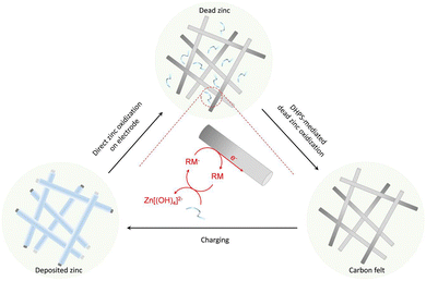
Here, redox-mediated zinc chemistry is proposed to ultimately solve the “dead zinc” problem in alkaline systems. As shown in Fig. 1, upon the depletion of “active zinc” (on electrode) during a discharge process, a redox mediator (RM), which is dissolved in electrolyte and has a higher potential than zinc, would further oxidize the “dead zinc” chemically. The reduced RM− then shuttles back to the electrode, where it is regenerated electrochemically. With such a closed-loop redox-mediated chemical–electrochemical cycle, the “dead zinc”, which is electrically segregated from the electrode or inaccessible in a regular discharge process, would indirectly while constantly be revitalized. As such, the inactive zinc would be instantly eliminated without accumulation during each discharge process, and the detrimental effect would be mitigated. In this study, 7,8-dihydroxyphenazine-2-sulfonic acid (DHPS) was used as the RM because of its suitable redox potential, high chemical stability and fast reaction rate under alkaline conditions.21,22 With the DHPS-mediated strategy, an alkaline zinc–iron flow battery (AZIFB) using Zn as the anode and ferricyanide as catholyte active species has demonstrated drastically enhanced cycling stability at high areal capacity of Zn of up to 250 mA h cm−2 at near unity zinc utilization. In particular, a cell with a Zn areal capacity of 152 mA h cm−2 could operate at nearly 100% depth of discharge (DOD) and a current density of 50 mA cm−2 for more than 1500 hours with a capacity fading rate of 0.019% per day (0.0048% per cycle). We anticipate that such a redox-mediated strategy would have broad applicability in other electrolyte systems involving solid/liquid phase transformation reactions.
Results and discussion
DHPS-mediated zinc chemistry
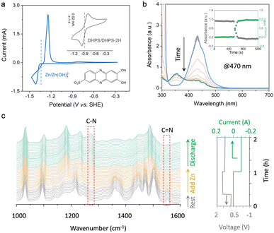
The degradation mechanism of Zn anodes in alkaline electrolytes was first scrutinized with a zinc-based symmetric flow cell. The cell was cycled at a current density of 50 mA cm−2 and nearly 100% DOD (charged to the theoretical capacity of zinc or a cutoff voltage, whichever is reached first, and fully discharged to a cutoff voltage, and the DOD was calculated based on the discharge capacity and theoretical capacity of the zinc anode), with an areal capacity of 92 mA h cm−2. As shown in Fig. S1a (ESI†), the cell ran steadily for around 60 cycles and then revealed a rapid capacity decay with a fading rate of ∼0.99 mA h cm−2 per cycle. Silver-gray particles were observed in the external tank with electrolyte circulation (Fig. S1b, ESI†), in which the “dead zinc” formed during the cycling process. In addition, SEM images of the electrode after cycling show mostly a smooth surface of carbon felt, but with a few small particles (Fig. S2, ESI†), which were identified to be Zn(OH)2 (Fig. S3, ESI†). This is presumably caused by the hydrogen evolution reaction, in which zinc corrodes inducing the formation of the Zn(OH)2 precipitate.16 Obviously, it is not the small amount of the Zn(OH)2 precipitate, but the silver-gray “dead zinc” observed in the tank that is responsible for the large capacity decay. To recover the capacity loss induced by “dead zinc”, the redox-targeting concept is introduced to the anolyte system, with which the oxidation of the zinc via a redox-mediated chemical process with a suitable RM is anticipated to effectively solve the problem.The half-wave potentials (E1/2) of DHPS and Zn were measured by cyclic voltammetry (CV). As shown in Fig. 2a, the E1/2 of DHPS/DHPS-2H and [Zn(OH)4]2−/Zn couples is −0.90 V and −1.30 V (vs. SHE), respectively. Thus, the driving force of the DHPS-mediated zinc oxidation reaction can be as large as 0.40 V. When 20 mM DHPS was added into the anolyte with “dead zinc” sediments, the silver-gray particles gradually dissolved, showing that zinc could be oxidized by DHPS and forms soluble species in alkaline solution (Fig. S4, ESI†). In comparison, the small Zn(OH)2 particles on carbon felt remain unchanged (Fig. S5, ESI†) after soaking in the DHPS-containing anolyte for 24 hours. The reaction between DHPS and zinc was further monitored by in situ UV-Vis spectroscopy through a spectroelectrochemical flow cell (see setup in Fig. S6, ESI†). The UV-Vis spectrum of DHPS solution showed major absorption at around 435 nm which became attenuated after adding excess zinc. Meanwhile, another absorption peak at 354 nm arising from the formation of DHPS-2H emerged and became stronger with reaction (Fig. 2b). The concentration changes of DHPS and DHPS-2H are calculated based on the standard calibration curve (Fig. S7, ESI†). After adding zinc in DHPS solution, the absorbance of DHPS-2H at 470 nm shot up nearly instantaneously and reached a steady state in a short time, suggesting a swift reaction which will be further discussed later. The concentration of DHPS-2H was stabilized at 1.1 mM, while that of DHPS was reduced from 1.4 to 0.3 mM, indicating that the chemical reaction between zinc and DHPS can be triggered even with a small amount of DHPS in the electrolyte.
To elucidate the mechanism of the DHPS-mediated zinc oxidation reaction, attenuated total reflection (ATR) Fourier-transform infrared (FTIR) spectroscopy was conducted at different stages of the reaction, with which the bonding information of DHPS could be detected in real-time (see setup in Fig. S8, ESI†). As shown in Fig. 2c, the stretching vibration of C![[double bond, length as m-dash]](https://www.rsc.org/images/entities/char_e001.gif) N at 1550 cm−1 which was clearly observed during the resting process gradually decreased after adding zinc into the electrolyte.23 In the meantime, a new peak at 1272 cm−1 assigned to the formation of a C–N bond appeared, indicative of the reduction of DHPS.24 Interestingly, during the subsequent discharge process, no obvious C
N at 1550 cm−1 which was clearly observed during the resting process gradually decreased after adding zinc into the electrolyte.23 In the meantime, a new peak at 1272 cm−1 assigned to the formation of a C–N bond appeared, indicative of the reduction of DHPS.24 Interestingly, during the subsequent discharge process, no obvious C![[double bond, length as m-dash]](https://www.rsc.org/images/entities/char_e001.gif) N vibration reappeared while the C–N group of reduced DHPS remained, indicating that the DHPS-mediated zinc oxidation process reached a steady state. The two-step closed-loop DHPS-mediated zinc oxidation chemistry is described below. During the discharge process, DHPS-2H is electrochemically oxidized by losing electrons to the electrode:
N vibration reappeared while the C–N group of reduced DHPS remained, indicating that the DHPS-mediated zinc oxidation process reached a steady state. The two-step closed-loop DHPS-mediated zinc oxidation chemistry is described below. During the discharge process, DHPS-2H is electrochemically oxidized by losing electrons to the electrode:
| DHPS-2H + 2OH− − 2e− → DHPS + 2H2O | (1) |
| DHPS + 2OH− + Zn + 2H2O → DHPS-2H + Zn(OH)42− | (2) |
Kinetics study
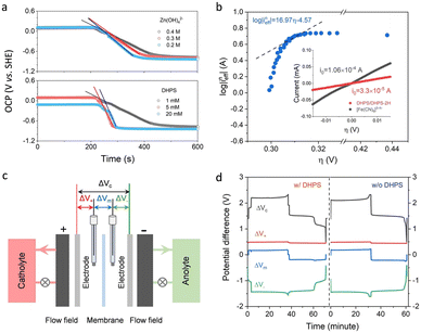
The reaction rate between DHPS and zinc is important for the rate performance of flow cells and dictated by different parameters, such as the concentration of [Zn(OH)4]2− in electrolyte, mass transport of DHPS, the energy barrier for interfacial charge transfer, etc.25,26 So, the kinetics study was first conducted by monitoring the open circuit potential (OCP) changes of DHPS in the presence of excess zinc powder.27 The whole reaction process was protected with N2 gas with a rotating disk electrode (RDE) as the working electrode (WE) and a Hg/HgO electrode as the reference electrode (RE). Fig. 3a and Fig. S9 (ESI†) show the OCP changes with time and the slope (b): | (3) |
 | (4) |
 | (5) |
 | (6) |
 | (7) |
 ), where
  is constant, a linear relationship between b and ineff is obtained. Thus, a larger slope (b) would correspond to a faster reaction rate. As shown in Fig. 3a, with increasing concentration of [Zn(OH)4]2− or decreasing concentration of DHPS, the slope of OCP vs. time decreases, indicating an attenuated reaction rate between DHPS and zinc.
Considering that the presence of soluble [Zn(OH)4]2− in the electrolyte may affect the OCP measurement of DHPS/DHPS-2H,30 the concentration of DHPS was determined by in situ UV-Vis spectroscopy. Since there is a large potential difference between DHPS/DHPS-2H and [Zn(OH)4]2−/Zn, Tafel behavior between ineff and η is expected, which allows the determination of the exchange current i0:
 | (8) |
![[thin space (1/6-em)]](https://www.rsc.org/images/entities/char_2009.gif) (ineff) vs. η, while a clear deviation is observed (see the dashed line by setting α as 1 for a one-way charge transfer process31). Considering that at low η the concentration of DHPS drops to a relatively low level, such a deviation could be rationalized by the presence of trace oxygen which rapidly oxidizes DHPS-2H and attenuates the drop in the DHPS concentration, and thus the effective reaction flux ineff. i0 is estimated to be around 2.7 × 10⁻⁵ A by extrapolating the dashed line to an intercept of log
(ineff) vs. η, while a clear deviation is observed (see the dashed line by setting α as 1 for a one-way charge transfer process31). Considering that at low η the concentration of DHPS drops to a relatively low level, such a deviation could be rationalized by the presence of trace oxygen which rapidly oxidizes DHPS-2H and attenuates the drop in the DHPS concentration, and thus the effective reaction flux ineff. i0 is estimated to be around 2.7 × 10⁻⁵ A by extrapolating the dashed line to an intercept of log![[thin space (1/6-em)]](https://www.rsc.org/images/entities/char_2009.gif) (i0). Note that i0 for DHPS/DHPS-2H on the glassy carbon electrode is around 3.3 × 10⁻⁵ A (see the inset of Fig. 3b), which is comparable to the redox-targeting reaction rate on zinc. Thus, the fast reaction rate between DHPS and Zn would ensure a good rate performance of the cell without the formation of “dead zinc”.
(i0). Note that i0 for DHPS/DHPS-2H on the glassy carbon electrode is around 3.3 × 10⁻⁵ A (see the inset of Fig. 3b), which is comparable to the redox-targeting reaction rate on zinc. Thus, the fast reaction rate between DHPS and Zn would ensure a good rate performance of the cell without the formation of “dead zinc”.
In addition to the comparable CV peak current, the peak-to-peak separation (ΔE) between the anodic and cathodic peak potentials of zinc was ∼0.17 V regardless of the presence of DHPS in the electrolyte (Fig. 2a and Fig. S10, ESI†), indicating that DHPS has no noticeable effect on the reaction of [Zn(OH)4]2−/Zn. Furthermore, four-electrode measurements with two Hg/HgO reference electrodes (REs) in both the positive and negative electrode compartments (Fig. 3c) were conducted to monitor the local voltage drop across the different cell components of Zn/[Fe(CN)6]3−/4− flow cells with and without DHPS in anolyte.32,33 As shown in Fig. 3d, the voltage drops ΔV+ between the positive electrode and RE1, ΔV− between the negative electrode and RE2, ΔVm between RE1 and RE2 across the membrane, and ΔVc between the positive and negative electrodes were monitored during the charge and discharge processes at a current density of 30 mA cm−2. The differences of ΔV− between the charge and discharge processes for the anolyte with and without DHPS are 42 and 47 mV, respectively, suggesting that the presence of DHPS has no adverse effect on zinc reaction kinetics. Similar results were also obtained from the 4-electrode measurement of a DHPS/[Fe(CN)6]3−/4− flow cell in the absence of zinc (Fig. S11, ESI†).
Zinc-based symmetric flow cells
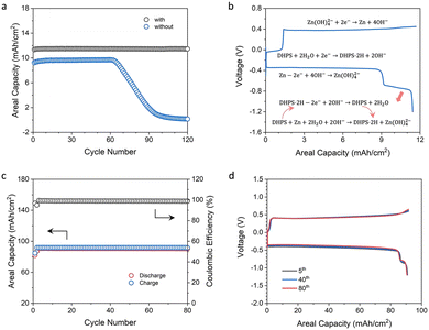
Zinc-based symmetric flow cells were assembled to study the role and performance of DHPS. Fig. 4a shows the cycling stability of flow cells with and without DHPS in anolyte at a current density of 20 mA cm−2 and nearly 100% DOD (charged to the theoretical capacity of zinc and fully discharged to a cutoff voltage) and at a relatively low areal capacity of zinc (12.2 mA h cm−2). The cell without DHPS in the anolyte can be stably cycled for 62 cycles with an areal capacity of 9.60 mA h cm−2 and then gradually decreased to nearly zero at a capacity fading rate of about 0.27 mA h cm−2 per cycle. Such an evolution of capacity may arise from the incomplete stripping of zinc in the first discharge as a result of side reactions and inflated polarization at the end of discharge (the area of the zinc plate shrunk). The capacity dropped rapidly as the unreacted zinc was depleted in the subsequent cycles. In stark contrast, in the presence of 20 mM DHPS in anolyte, the battery can be cycled with an areal capacity of 11.5 mA h cm−2, and there was no obvious capacity decay in the first 120 cycles. Its capacity started to drop from the 125th cycle, while it was instantaneously recovered with the replacement of the counter electrode indicating that the capacity fading originated from the depletion of active zinc on the counter electrode (Fig. S12, ESI†). The representative voltage profiles of the cell are shown in Fig. 4b. During the discharge process, the long high-voltage plateau corresponds to the stripping of active zinc on the electrode, and it follows a short low-voltage plateau of the oxidation of DHPS-2H and the associated DHPS-mediated “dead zinc” oxidation. This is substantiated by the high capacity of the second plateau compared to the theoretical capacity of DHPS (2.2 mA h cm−2vs. 1.6 mA h cm−2). Moreover, the surface of the carbon felt electrode after cycling was as clean as that of the pristine one in the presence of DHPS in anolyte (see the SEM images in Fig. S13, ESI†). In contrast, some spots of Zn(OH)2 and ZnO deposits were observed on carbon felt in the absence of DHPS (Fig. S14, ESI†).To further assess the ability of DHPS to revitalize the “dead zinc”, a symmetric flow cell with a higher areal capacity (92.0 mA h cm−2) of zinc and 20 mM DHPS in anolyte was tested at a current density of 50 mA cm−2 and nearly 100% DOD. As shown in Fig. 4c, the cell exhibited a discharge capacity of ∼90.8 mA h cm−2 and a Coulombic efficiency (CE) of 98.9%. Considering that the cell was charged to the theoretical capacity of zinc and fully discharged, the CE also broadly corresponds to the utilization rate of zinc in each cycle given that the discharge capacity of DHPS is negligible (Fig. 4d). The capacity of “dead zinc” increased from 0.89 mA h cm−2 to 1.00 mA h cm−2 with increasing areal capacity of zinc from 12.2 mA h cm−2 to 92.0 mA h cm−2, indicating that more “dead zinc” was formed at higher areal capacity. Cumulative discharge capacity was employed to assess the cycling stability of the DHPS-mediated zinc symmetric flow cell (Fig. S15, ESI†),34 and was determined to be 7.08 Ah cm−2 after 78 cycles (theoretically 7.11 Ah cm−2), corresponding to a remarkably low capacity fading rate of 0.005% per cycle. Importantly, there was no deterioration in polarization of the voltage profiles during the entire cycling process (Fig. 4d) and the morphology of the carbon felt after cycling was nearly as clean as that of the pristine one (Fig. S16 and S17, ESI†). These results corroborate the ultra-stable cycling performance of the DHPS-mediated zinc oxidation process under operation conditions, showing great promise in zinc-based full cell application.
Alkaline zinc-iron flow batteries (AZIFBs)
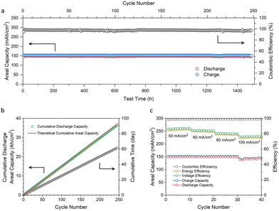
With the promising results of symmetric cells and kinetics study, we further investigated the DHPS-mediated “dead zinc” revitalization process in Zn/[Fe(CN)6]3−/4−-based deep-cycle flow battery full cells. The kinetics study in Fig. 3a shows that a higher concentration of DHPS from 1 mM to 5 mM would lead to a faster reaction rate between DHPS and zinc metal. But when the concentration was further increased to 20 mM, the reaction rate did not show a significant improvement. Considering that a higher DHPS concentration would lead to an increased electrolyte viscosity, which may induce an adverse effect on the battery performance, 30 mM DHPS was used in the subsequent full cell tests.The cycling performance of an AZIFB with a zinc areal capacity of 152 mA h cm−2 was tested at a current density of 50 mA cm−2 (Fig. 5a). With 30 mM DHPS in anolyte, the AZIFB exhibited ultra-stable cycling performance for over 1500 hours with an average CE of 97.5%. As the cell was charged to the theoretical capacity of zinc loaded in the cell, the utilization of zinc is suggested to be nearly unity during the entire cycling process. The capacity fading rate was determined based on the cumulative discharge capacity over the cycle number and time (Fig. 5b), which was determined to be 36.7 Ah cm−2 after 247 cycles (from the 2nd cycle to 248th cycle). Considering that the theoretical cumulative value is 37.1 Ah cm−2 (based on the discharge capacity of the 2nd cycle), the capacity fading rate is calculated to be 0.0048% per cycle or 0.019% per day, corresponding to a 93.3% capacity retention after 1 year of continuous operation. This represents the best reported cycling performance for deep-cycle zinc-based flow cells (Table S1, ESI†). Moreover, the carbon felt remains intact after such a long cycling process (Fig. S18 and S19, ESI†). An AZIFB without DHPS in anolyte was also tested (Fig. S20, ESI†) under the same conditions (an areal capacity of 152 mA h cm−2 and a current density 50 mA cm−2), and showed a rapid capacity decay from the 30th cycle with a fading rate of 3.5 mA h cm−2 per cycle. These results collectively attest the efficacy of DHPS-mediated zinc chemistry in battery cycling performance.
Fig. 5c shows the rate performance of an AZIFB using a Nafion 212 membrane measured at current densities from 50 to 100 mA cm−2. The areal capacity of the zinc anode was kept at 152 mA h cm−2 (nearly 100% DOD of zinc) for current densities from 50 to 80 mA cm−2, while for a current density of 100 mA cm−2 the capacity was slightly lower (∼145 mA h cm−2) as the charging voltage was limited to 2.10 V. The CE of the cell remained stable at 98.4–98.9% with increasing current densities, while the voltage efficiency (VE) and energy efficiency (EE) slightly decreased owing to the inflated Ohmic and activation polarizations, yielding an EE of over 75% at a current density as high as 100 mA cm−2. The voltage profiles of the AZIFBs at different current densities are shown in Fig. S21 (ESI†). The long plateaus of the discharge and charge curves are respectively associated with zinc oxidation and [Zn(OH)4]2− reduction processes, while the short plateaus correspond to those of DHPS-2H and DHPS. Moreover, the discharge capacity of DHPS-2H was larger than the charge capacity of DHPS, the difference of which indicates that a similar amount of “dead zinc” was restored by DHPS. This value became slightly higher with increasing current density (from 1.2 mA h cm−2 at 50 mA cm−2 to 3.5 mA h cm−2 at 100 mA cm−2), indicating that more “dead zinc” was formed upon fast plating and stripping. Nevertheless, the similar CE suggests a complete capacity recovery even at a high current density, substantiating the fast reaction rate between “dead zinc” and DHPS.
To gain further insight into the effect of DHPS on Zn deposition during the charge process, we characterized the morphology of deposited Zn (152 mA h cm−2 at 50 mA cm−2) on the anodic carbon felt. From the SEM images, it seems that the presence of DHPS has no obvious influence on Zn deposition, which shares a similar morphology to those reported in the literature.35 The top view of the carbon felt electrode in Fig. S22 (ESI†) shows that the deposited Zn varies from micrometer sized “boulder-like” particles with clear crystal facets surrounding single carbon fibers to sub-micrometer “moss-like” porous deposits filled in between the fibers. In comparison, the porous Zn deposit predominates inside the carbon felt as seen from the cross-sectional view in Fig. S23 (ESI†).
In addition to the cycling stability of the Zn electrode, the areal capacity is another crucial design parameter for AZIFBs. For a given total electrode area (or power), a higher areal capacity of Zn leads to a higher energy, particularly useful for long-duration energy storage applications. Similarly, for a given energy requirement, a higher areal capacity of Zn would necessitate a smaller electrode area (or the number of single cells in a stack) if the power requirement is met, which reduces the cost (see the ESI† for more discussion). To evaluate the DHPS-mediated Zn chemistry at high areal capacity, AZIFBs with 200 and 250 mA h cm−2 Zn loading were tested at 80 mA cm−2 and nearly 100% DOD (Fig. S24 and S25, ESI†). Good cycling stability with an average CE of 97.4% and 96.4% was achieved at such a high current density and depth of discharge, respectively, revealing the robustness of the DHPS-mediated Zn oxidation reaction for practical applications.
Besides the above, the presence of DHPS in the anolyte may offer additional benefits to the operation of AZIFB cell stacks in preventing over-discharge and detrimental polarity reversal of individual cells particularly at high currents, considering that all the anodic compartments are accessible to the soluble DHPS in anolyte. Any capacity variation of individual cells induced by the non-uniform plating/stripping of zinc or side reactions would be homogenized by the redox-targeting reactions and compensated for by the formed DHPS-2H at the end of discharge.
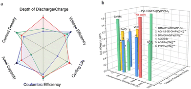
Fig. 6 shows the comparison of the various performance indicators of the redox-mediated AZIFB with those of other reported AZIFBs and aqueous redox-flow batteries (see the detailed data in Tables S2 and S3, ESI†). The superior overall cell performance makes the redox-mediated AZIFB a compelling candidate for large-scale stationary energy storage. While the above results are promising, for alkaline Zn-based flow batteries, the limited solubility of [Zn(OH)4]2− (or ZnO) at high pH which commonly entails a low volumetric capacity of the anolyte, should be addressed for high density energy storage. As shown in Fig. S26 (ESI†), the solubility of ZnO in 3.8 M NaOH is around 0.5 M, which is translated into a volumetric capacity of only 26.8 Ah L−1. As it is beyond the scope of this work for the ultra-stable and deep-cycle Zn electrode system, potential solutions will be discussed in forthcoming studies.
Conclusions
In summary, DHPS-mediated zinc chemistry was studied for the first time in alkaline Zn-based flow cells to revitalize the capacity of “dead zinc”. The presence of a low concentration of DHPS in the anolyte, resorting to the fast redox-targeting reaction with the inactive zinc, leads to remarkably enhanced cycling performance of the zinc electrode under high areal capacity and deep-cycle conditions. Based on this strategy, an ultra-stable AZIFB with a high zinc loading of 152 mA h cm−2 was demonstrated at 50 mA cm−2 and nearly 100% DOD, which presented an ultralow capacity fading rate of 0.019% per day (0.0048% per cycle) for more than 1500 hours. Furthermore, the AZIFB achieved a high zinc utilization of 96.4% at an even higher areal capacity of 250 mA h cm−2 and a current density of 80 mA cm−2 during prolonged cycling. With the rigorous tests, the approach demonstrated in this work provides a credible solution to the long-lifetime and deep-cycle application of alkaline Zn-based flow cells at high material loading and current density. In addition to zinc-based systems, the redox-mediated approach is expected to provide an effective way to universally address the capacity loss issue of other metal-based batteries under different electrolyte conditions.Author contributions
Q. W. and S. H. conceived the study. Q. W. and X. L. supervised the work. S. H. performed most of the experiments. Z. Y. conducted the rate test. M. S. synthesised DHPS. X. W., H. Z., S. P. H. and D. L. assisted the data analysis. S. H. and Q. W. wrote the paper.Conflicts of interest
There are no conflicts to declare.Acknowledgements
This research is supported by the National Research Foundation, Prime Minister's Office, Singapore, under its Investigatorship Programme (Award No. NRF-NRFI2018-06).References
- W. A. Braff, J. M. Mueller and J. E. Trancik, Nat. Clim. Change, 2016, 6, 964–969 CrossRef.
- B. Dunn, H. Kamath and J.-M. Tarascon, Science, 2011, 334, 928–935 CrossRef CAS.
- M. Armand and J. M. Tarascon, Nature, 2008, 451, 652–657 CrossRef CAS PubMed.
- G. L. Soloveichik, Chem. Rev., 2015, 115, 11533–11558 CrossRef CAS PubMed.
- Z. Li and Y.-C. Lu, Adv. Mater., 2020, 32, 2002132 CrossRef CAS PubMed.
- Z. Yuan, Y. Yin, C. Xie, H. Zhang, Y. Yao and X. Li, Adv. Mater., 2019, 31, 1902025 CrossRef CAS PubMed.
- F. Zhang, M. Gao, S. Huang, H. Zhang, X. Wang, L. Liu, M. Han and Q. Wang, Adv. Mater., 2021, 2104562 Search PubMed.
- E. Sum, M. Rychcik and M. Skyllas-kazacos, J. Power Sources, 1985, 16, 85–95 CrossRef CAS.
- M. Skyllas-Kazacos, M. Rychcik, R. G. Robins, A. G. Fane and M. A. Green, J. Electrochem. Soc., 1986, 133, 1057–1058 CrossRef CAS.
- G. Kear, A. A. Shah and F. C. Walsh, Int. J. Energy Res., 2012, 36, 1105–1120 CrossRef CAS.
- H. Zhang, W. Lu and X. Li, Electrochem. Energy Rev., 2019, 2, 492–506 CrossRef CAS.
- J. Luo, B. Hu, M. Hu, Y. Zhao and T. L. Liu, ACS Energy Lett., 2019, 4, 2220–2240 CrossRef CAS.
- K. Gong, X. Ma, K. M. Conforti, K. J. Kuttler, J. B. Grunewald, K. L. Yeager, M. Z. Bazant, S. Gu and Y. Yan, Energy Environ. Sci., 2015, 8, 2941–2945 RSC.
- J. Luo, B. Hu, M. Hu, W. Wu and T. L. Liu, Angew. Chem., Int. Ed., 2022, 61, e202204030 CAS.
- Q. Yang, Q. Li, Z. Liu, D. Wang, Y. Guo, X. Li, Y. Tang, H. Li, B. Dong and C. Zhi, Adv. Mater., 2020, 32, 2001854 CrossRef CAS PubMed.
- W. Lu, C. Zhang, H. Zhang and X. Li, ACS Energy Lett., 2021, 6, 2765–2785 CrossRef CAS.
- Y. Cheng, N. Zhang, Q. Wang, Y. Guo, S. Tao, Z. Liao, P. Jiang and Z. Xiang, Nano Energy, 2019, 63, 103822 CrossRef CAS.
- B. Li, Z. Nie, M. Vijayakumar, G. Li, J. Liu, V. Sprenkle and W. Wang, Nat. Commun., 2015, 6, 6303 CrossRef CAS PubMed.
- J. Zheng, Q. Zhao, T. Tang, J. Yin, D. Quilty Calvin, D. Renderos Genesis, X. Liu, Y. Deng, L. Wang, C. Bock David, C. Jaye, D. Zhang, S. Takeuchi Esther, J. Takeuchi Kenneth, C. Marschilok Amy and A. Archer Lynden, Science, 2019, 366, 645–648 CrossRef CAS PubMed.
- Z. Yuan, X. Liu, W. Xu, Y. Duan, H. Zhang and X. Li, Nat. Commun., 2018, 9, 3731 CrossRef PubMed.
- A. Hollas, X. Wei, V. Murugesan, Z. Nie, B. Li, D. Reed, J. Liu, V. Sprenkle and W. Wang, Nat. Energy, 2018, 3, 508–514 CrossRef CAS.
- F. Zhang, H. Zhang, M. Salla, N. Qin, M. Gao, Y. Ji, S. Huang, S. Wu, R. Zhang, Z. Lu and Q. Wang, J. Am. Chem. Soc., 2021, 143, 223–231 CrossRef CAS PubMed.
- T. Sun, C. Liu, J. Wang, Q. Nian, Y. Feng, Y. Zhang, Z. Tao and J. Chen, Nano Res., 2020, 13, 676–683 CrossRef CAS.
- L. Li, L. Chen, Y. Wen, T. Xiong, H. Xu, W. Zhang, G. Cao, Y. Yang, L. Mai and H. Zhang, J. Mater. Chem. A, 2020, 8, 26013–26022 RSC.
- J. T. Kim and J. Jorné, J. Electrochem. Soc., 1980, 127, 8–15 CrossRef CAS.
- L. P. Sanford and S. M. Crawford, Limnol. Oceanogr., 2000, 45, 1180–1186 CrossRef CAS.
- H. Zhang, F. Zhang, J. Yu, M. Zhou, W. Luo, Y. M. Lee, M. Si and Q. Wang, Adv. Mater., 2021, 33, 2006234 CrossRef CAS PubMed.
- M. Zhou, Q. Huang, T. N. Pham Truong, J. Ghilane, Y. G. Zhu, C. Jia, R. Yan, L. Fan, H. Randriamahazaka and Q. Wang, Chem, 2017, 3, 1036–1049 CAS.
- M. Zhou, Y. Chen, Q. Zhang, S. Xi, J. Yu, Y. Du, Y.-S. Hu and Q. Wang, Adv. Energy Mater., 2019, 9, 1901188 CrossRef.
- H. Zhou, J. H. Park, F.-R. F. Fan and A. J. Bard, J. Am. Chem. Soc., 2012, 134, 13212–13215 CrossRef CAS PubMed.
- S. Huang, H. Zhang, J. Zhuang, M. Zhou, M. Gao, F. Zhang and Q. Wang, Adv. Energy Mater., 2022, 2103622 CrossRef CAS.
- M. Gao, S. Huang, F. Zhang, Y. M. Lee, S. Huang and Q. Wang, Mater. Today Energy, 2020, 18, 100540 CrossRef CAS.
- G.-M. Weng, Z. Li, G. Cong, Y. Zhou and Y.-C. Lu, Energy Environ. Sci., 2017, 10, 735–741 RSC.
- Y. Chen, M. Zhou, Y. Xia, X. Wang, Y. Liu, Y. Yao, H. Zhang, Y. Li, S. Lu, W. Qin, X. Wu and Q. Wang, Joule, 2019, 3, 2255–2267 CrossRef CAS.
- R. Y. Wang, D. W. Kirk and G. X. Zhang, J. Electrochem. Soc., 2006, 153, C357 CrossRef CAS.
Footnote |
| † Electronic supplementary information (ESI) available. See DOI: https://doi.org/10.1039/d2ee02402k |
| This journal is © The Royal Society of Chemistry 2023 |

