 Open Access Article
Creative Commons Attribution 3.0 Unported Licence
C–N linked donor type porphyrin derivatives: unrevealed hole-transporting materials for efficient hybrid perovskite solar cells†
Melani J. A.
Reis‡
a,
Ana T.
Nogueira‡
bc,
Ana
Eulálio
bc,
Nuno M. M.
Moura
 *a,
Joana
Rodrigues
 d,
Dzmitry
Ivanou
bc,
Paulo E.
Abreu
 e,
M. Rosário P.
Correia
 d,
Maria G. P. M. S.
Neves
 a,
Ana M. V. M.
Pereira
 *bc and
Adélio
Mendes
 bc
bc
aLAQV-Requimte and Department of Chemistry, University of Aveiro, 3010-193 Aveiro, Portugal. E-mail: nmoura@ua.pt
bLEPABE – Laboratory for Process Engineering, Environment, Biotechnology and Energy, Faculty of Engineering, University of Porto, Rua Dr Roberto Frias, 4200-465 Porto, Portugal. E-mail: mafaldapereira@fe.up.pt
cALiCE – Associate Laboratory in Chemical Engineering, Faculty of Engineering, University of Porto, Rua Dr Roberto Frias, 4200-465 Porto, Portugal
di3N, Department of Physics, University of Aveiro, 3810-193 Aveiro, Portugal
eUniversity of Coimbra, Centro de Química de Coimbra, Department of Chemistry, Coimbra 3004-535, Portugal
First published on 25th July 2023
Abstract
A new series of Zn(II) and Cu(II)-based porphyrin complexes 5a and 5b doubly functionalised with carbazole units were developed to be used as hole-transporting materials (HTMs) in perovskite solar cells (PSCs). These complexes were obtained via a nucleophilic substitution reaction mediated by PhI(OAc)2/NaAuCl4·2H2O, or using C–N transition metal-assisted coupling. The hole extraction capability of 5a and 5b was assessed using cyclic voltammetry; this study confirmed the better alignment of the Zn(II) complex 5a with the perovskite valence band level, compared to the Cu(II) complex 5b. The optimised geometry and molecular orbitals of both complexes also corroborate the higher potential of 5a as a HTM. Photoluminescence characterisation showed that the presence of 5a and 5b as HTMs on the perovskite surface resulted in the quenching of the emission, matching the hole transfer phenomenon. The photovoltaic performance was evaluated and compared with those of reference cells made with the standard HTM spiro-OMeTAD. The optimised 5-based devices showed improvements in all photovoltaic characteristics; their open circuit voltage (Voc) reached close to 1 V and short-circuit current density (Jsc) values were 13.79 and 9.14 mA cm−2 for 5a and 5b, respectively, disclosing the effect of the metallic centre. A maximum power conversion efficiency (PCE) of 10.01% was attained for 5a, which is 65% of the PCE generated by using the spiro-OMeTAD reference. This study demonstrates that C–N linked donor-type porphyrin derivatives are promising novel HTMs for developing efficient and reproducible PSCs.
1. Introduction
Nowadays, it is unquestionable that to meet the rapidly growing global energy demand and avoid large amounts of greenhouse gas emissions, renewable energy sources need to be exploited to the maximum extent. Indeed, solar power is the world's most abundant energy resource, and harnessing it would yield a never-ending energy supply.1 Nonetheless, the greatest challenge has always been the development of efficient and cost-effective approaches to solar energy conversion. Photovoltaic (PV) technology is touted as the most promising pathway and the global PV market is currently being dominated by crystalline silicon solar cells, which have demonstrated a high power conversion efficiency (PCE) of 26.1%.2 A cutting-edge breakthrough is now perovskite solar cells (PSCs).3,4 The progress in this emerging technology is so impressive that from the first example reported in 2009 with a PCE of 3.8%,5 the value increased to 12–16% by mid-2012 and 2013 and to a certified PCE of 26.0% in 2023.2c Most of these achievements are due to the presence of light absorbers based on lead perovskite materials, which exhibit broad absorption in the solar spectrum combined with high charge carrier mobility and low recombination. Even so, one of the most important technical improvements came from replacing the liquid redox mediator with a p-type solid-state hole-transporting material (HTM) that is crucial for long-term stability. Moreover, even if PSC devices can work without the HTM, this active layer is essential for high performance as it facilitates charge carrier separation and extraction by transporting holes from the perovskite material to the cathode whilst reducing unwanted charge recombination. Currently, typical n–i–p structured PSCs generally use 2,2′,7,7′-tetrakis[N,N′-di(4-methoxyphenyl)amino]-9,9′-spirobifluorene (spiro-OMeTAD) as the HTM. Nevertheless, spiro-OMeTAD production costs are high due to the laborious and complex multistep synthesis, resulting in a low yield, combined with a complicated purification process. Furthermore, additives and dopants are needed to improve the spiro-OMeTAD hole mobility capacity, and those accelerate perovskite decomposition to cause detrimental effects on the long-term stability of the whole device. Accordingly, tremendous efforts have been devoted to developing alternative HTMs.6,7 Low-cost carbazole-based molecules, bearing a wide variety of functional groups to fine-tune electronic and optical properties, have attracted much attention due to PSC performances equalising that of spiro-OMeTAD.8–10 Meanwhile, porphyrins, due to their high thermal stability and efficient light-harvesting throughout a large portion of the solar emission spectrum, easily tailored peripheral and non-peripheral substituents, and tuneable optical and electronic properties, have shown their great potential as HTMs since the pioneering work carried out in 2016.11,12 In this first literature report, Zn(II) porphyrin–ethynylaniline conjugates as HTMs in PSCs generated a PCE of 16.6%.13 Later, Chen et al. reported the use of Zn(II) and Cu(II) complexes of 5,10,15,20-tetrakis{4-[N,N-di(4-methoxyphenyl)amino-phenyl]}porphyrin with outstanding thermal and electrochemical stability. Under the same operating conditions, whilst the Zn(II) complex gave rise to a PCE of 17.78%, comparable to the spiro-OMeTAD PCE of 18.59%, the Cu(II) complex contributed only a PCE of 15.36%.14 In 2018, a PCE of 18.85% resulted from the utilisation of a Zn(II) porphyrin bearing fluorinated triphenylamine substituents as the HTM. In the same study, efficiencies of 17.71% and 16.37% were reported for non-fluorinated versions, and all these outcomes are a consequence of incorporating F substituents in the periphery of the porphyrin core that creates an increase in charge injection/transfer of the devices due to the better-matched HOMO level and improved hole mobility.15 Besides, Chiang et al. combined triple cation perovskites with porphyrin dimers incorporating ethynylaniline moieties to achieve a PCE of 19.44%, outperforming the widely used spiro-OMeTAD (18.62%).16 In a broader context, it has been proven that triarylamine substituents in the porphyrin cores have a deep impact on energy levels to play an important role in enhancing charge transport in the amorphous HTM film and thus in improving the PSC device performance. However, there are no reports on the effects of directly N-linking N-donors to the porphyrin core in the field of HTMs, apart from the work conducted by Cho et al. describing Zn(II)-phthalocyanines substituted with secondary amine donor groups, including diphenylamine and carbazole derivatives, as a mixture of positional isomers reaching a maximum PCE of 11.75% for the diphenylamino-substituted macrocycle vs. a spiro-OMeTAD-based device achieving 16.78%.17According to previous studies, although the amino groups of meso-(diarylamino)porphyrins raise the porphyrin HOMO level, electronic perturbation is only moderate since the diarylamino groups twist out of the bulky porphyrin plane, minimising conjugation.18 We thus inferred that the introduction of bulky and completely planar N-electron-donating groups might be more fruitful due to the increased donating ability of the nitrogen lone pair participating in conjugation, together with the increased steric hindrance due to their completely planar configuration. Following this line of reasoning, Cu(II) and Zn(II)-based porphyrins doubly functionalised with carbazole were readily obtained and successfully used as HTMs in PSC devices. In the present study, also contributing to the fundamental understanding, dibrominated precursor structures, as well as meso-unsubstituted porphyrins, were used for the same purpose.
2. Experimental details
2.1. Materials
All chemical reagents and solvents employed in the synthetic procedures were of chemical or analytical grade and used without further purification. Preparative thin-layer chromatography was carried out on 20 × 20 cm glass plates coated with silica gel (0.5 mm thick). Column chromatography was carried out using silica gel (63–200 microns). Analytical TLC was carried out on pre-coated sheets with silica gel (0.2 mm thick). Commercial sources are Sigma-Aldrich, Merck, Acros, Fluorochem, Porphyrin-systems, Macherey-Nagel, and PanReac AppliChem. 5,15-Bis(3,5-di-tert-butylphenyl)porphyrin 2 and porphyrins 3a and 3b and 4a and 4b were synthesised under modified conditions reported in the literature.19–21 Detailed procedures are provided in the ESI.†2.2. Measurement and characterisation
![[thin space (1/6-em)]](https://www.rsc.org/images/entities/char_2009.gif) :
:![[thin space (1/6-em)]](https://www.rsc.org/images/entities/char_2009.gif) acetonitrile 3
acetonitrile 3![[thin space (1/6-em)]](https://www.rsc.org/images/entities/char_2009.gif) :
:![[thin space (1/6-em)]](https://www.rsc.org/images/entities/char_2009.gif) 1 mixture.
1 mixture.
![[thin space (1/6-em)]](https://www.rsc.org/images/entities/char_2009.gif) :
:![[thin space (1/6-em)]](https://www.rsc.org/images/entities/char_2009.gif) acetonitrile in a 3
acetonitrile in a 3![[thin space (1/6-em)]](https://www.rsc.org/images/entities/char_2009.gif) :
:![[thin space (1/6-em)]](https://www.rsc.org/images/entities/char_2009.gif) 1 volume ratio was used for electrochemical studies. The concentration of 5a, 5b, and conventional spiro-OMeTAD was 1.9 mM; all solutions contained the Bu4NPF6 salt as a supporting electrolyte at a concentration of 0.075 M. Prior to measurements, the solutions were deaerated by purging high purity Ar for ca. 5 min. Voltammograms were recorded at a potential scan rate of 100 mV s−1. During the measurement, the Ar flow was kept above the solution in the cell. Electrode potentials in voltammograms are quoted with regard to the equilibrium potential (E1/2) of the Fc+/Fc redox couple in the same mixture of solvents with 0.075 M Bu4NPF6 as the supporting electrolyte.
1 volume ratio was used for electrochemical studies. The concentration of 5a, 5b, and conventional spiro-OMeTAD was 1.9 mM; all solutions contained the Bu4NPF6 salt as a supporting electrolyte at a concentration of 0.075 M. Prior to measurements, the solutions were deaerated by purging high purity Ar for ca. 5 min. Voltammograms were recorded at a potential scan rate of 100 mV s−1. During the measurement, the Ar flow was kept above the solution in the cell. Electrode potentials in voltammograms are quoted with regard to the equilibrium potential (E1/2) of the Fc+/Fc redox couple in the same mixture of solvents with 0.075 M Bu4NPF6 as the supporting electrolyte.
Steady cyclic voltammograms of the GC electrode in Fc solutions, either in acetonitrile or in a mixture of solvents, are presented in the ESI in Fig. S1.†E1/2 of the Fc+/Fc couple for each solvent was defined as the midpoint between potentials corresponding to the oxidation and reduction peaks.
The HOMO energy levels were estimated from the onset potentials of oxidation (Eon Ox) using the equation
| EHOMO (eV) = −(5.1 + *Eon Ox + **0.042), |
![[thin space (1/6-em)]](https://www.rsc.org/images/entities/char_2009.gif) :
:![[thin space (1/6-em)]](https://www.rsc.org/images/entities/char_2009.gif) 1 volume ratio of the chlorobenzene
1 volume ratio of the chlorobenzene![[thin space (1/6-em)]](https://www.rsc.org/images/entities/char_2009.gif) :
:![[thin space (1/6-em)]](https://www.rsc.org/images/entities/char_2009.gif) acetonitrile mixture; **0.042 is the difference between E1/2 (Fc+/Fc) in mixed solvents and in acetonitrile. The difference reflects the solvent effect on the redox potential of the internal reference (Fc+/Fc) and must be used as a correction factor. The formal potential of the Fc+/Fc redox couple of −5.1 eV at the Fermi scale was obtained using the redox potential of ferrocene in pure acetonitrile.22
acetonitrile mixture; **0.042 is the difference between E1/2 (Fc+/Fc) in mixed solvents and in acetonitrile. The difference reflects the solvent effect on the redox potential of the internal reference (Fc+/Fc) and must be used as a correction factor. The formal potential of the Fc+/Fc redox couple of −5.1 eV at the Fermi scale was obtained using the redox potential of ferrocene in pure acetonitrile.22
2.3. Synthesis
![[thin space (1/6-em)]](https://www.rsc.org/images/entities/char_2009.gif) :
:![[thin space (1/6-em)]](https://www.rsc.org/images/entities/char_2009.gif) 1) as the eluent. After crystallisation from CH2Cl2/n-hexane, compound 5a was obtained in 51% yield (7.3 mg).
1) as the eluent. After crystallisation from CH2Cl2/n-hexane, compound 5a was obtained in 51% yield (7.3 mg).
If the solvent removal step was omitted, compound 5a was obtained in only 16% yield (2.4 mg).
1H NMR (500 MHz, CDCl3): δ 8.88 (4H, d, J = 4.8 Hz, β-H), 8.58 (4H, d, J = 4.8 Hz, β-H), 8.47 (4H, d, J = 8.0 Hz, 1′′,8′′-H), 8.03 (4H, d, J = 1.5 Hz, 2′,6′-H-Ph), 7.80–7.68 (2H, m, 2H, 4′-H-Ph), 7.46–7.37 (4H, m, 2′′,7′′-H), 7.41 (4H, t, J = 7.5 Hz, 3′′,6′′-H), 6.85 (4H, d, J = 8.0 Hz, 4′′,5′′-H), 1.54 (36H, s, tBu-C![[H with combining low line]](https://www.rsc.org/images/entities/char_0048_0332.gif) 3) ppm. 13C NMR (126 MHz, CDCl3): δ 151.4, 150.6, 148.8, 148.6, 140.8, 133.9 (β-C), 129.8 (β-C), 129.5 (2′,6′-C-Ph), 126.4 (3′′,6′′-CH), 123.5, 122.7, 121.2 (4′-CH-Ph), 120.4 (1′′,8′′-CH), 120.0 (2′′,7′′-CH), 113.7, 111.2 (4′′,5′′-CH), 36.4, 31.7 (tBu-
3) ppm. 13C NMR (126 MHz, CDCl3): δ 151.4, 150.6, 148.8, 148.6, 140.8, 133.9 (β-C), 129.8 (β-C), 129.5 (2′,6′-C-Ph), 126.4 (3′′,6′′-CH), 123.5, 122.7, 121.2 (4′-CH-Ph), 120.4 (1′′,8′′-CH), 120.0 (2′′,7′′-CH), 113.7, 111.2 (4′′,5′′-CH), 36.4, 31.7 (tBu-![[C with combining low line]](https://www.rsc.org/images/entities/char_0043_0332.gif) H3) ppm. UV-Vis (DMF): λmax (log
H3) ppm. UV-Vis (DMF): λmax (log![[thin space (1/6-em)]](https://www.rsc.org/images/entities/char_2009.gif) ε) 429.5 (5.34). 559 (4.03), 607.5 (3.65) nm. MS-ESI(+): m/z 1078.6 [M]+˙. HRMS-ESI(+): m/z calc. for 1078.4635 C72H66N6Zn [M]+˙ found 1078.4611.
ε) 429.5 (5.34). 559 (4.03), 607.5 (3.65) nm. MS-ESI(+): m/z 1078.6 [M]+˙. HRMS-ESI(+): m/z calc. for 1078.4635 C72H66N6Zn [M]+˙ found 1078.4611.
(i) Buchwald–Hartwig coupling: a Schlenk tube was charged with porphyrin 4b (10.2 mg, 0.011 mmol), carbazole (37.1 mg, 0.22 mmol, 20 equiv.), tBuONa (75.7 mg, 0.78 mmol, 71 equiv.), 18-crown-6 (0.9 mg, 0.0034 mmol, 0.3 equiv.), Pd(OAc)2 (1 mg, 0.0045 mmol, 0.4 equiv.), and rac-BINAP (4.2 mg, 0.0068 mmol, 0.6 equiv.). Next, the vessel was purged with nitrogen and N,N′-dimethylformamide/toluene (1![[thin space (1/6-em)]](https://www.rsc.org/images/entities/char_2009.gif) :
:![[thin space (1/6-em)]](https://www.rsc.org/images/entities/char_2009.gif) 2) (3 mL) was added. The reaction mixture was stirred at 120 °C for 2 days. The crude mixture was purified by preparative thin-layer chromatography using CH2Cl2/hexane (1
2) (3 mL) was added. The reaction mixture was stirred at 120 °C for 2 days. The crude mixture was purified by preparative thin-layer chromatography using CH2Cl2/hexane (1![[thin space (1/6-em)]](https://www.rsc.org/images/entities/char_2009.gif) :
:![[thin space (1/6-em)]](https://www.rsc.org/images/entities/char_2009.gif) 4) as the eluent. After crystallisation from CH2Cl2/n-hexane, compound 5b was isolated in 39% yield (4.7 mg).
4) as the eluent. After crystallisation from CH2Cl2/n-hexane, compound 5b was isolated in 39% yield (4.7 mg).
(ii) Ullmann coupling: porphyrin 4b (32 mg, 0.036 mmol) was dissolved in dimethylsulfoxide (1.5 mL) and the resulting mixture was purged with nitrogen for 5 min. Then, carbazole (59.4 mg, 0.36 mmol, 10 equiv.), N-phenylbenzohydrazide (3 mg, 0.014 mmol, 0.4 equiv.), CuI (1.4 mg, 0.007 mmol, 0.2 equiv.), and Cs2CO3 (46.3 mg, 0.14 mmol, 4 equiv.) were added. The resulting mixture was stirred at 120 °C under a nitrogen atmosphere for 5 days. After reaching room temperature, the reaction mixture was diluted with CH2Cl2, washed first with a saturated solution of NaHCO3, and, finally, with distilled water. Then, the organic phase was separated, and the solvent was removed under reduced pressure. The same conditions described in procedure (i) were used to purify the crude mixture and compound 5b was isolated in 31% yield (12.2 mg).
(iii) Nucleophilic reaction mediated by PhI(OAc) 2 /NaAuCl 4 ·2H 2 O: to a solution of porphyrin 4b (15.4 mg, 0.017 mmol) in CH2Cl2 (5 mL) carbazole (14.2 mg, 0.085 mmol, 5 equiv.), PhI(OAc)2 (5.5 mg, 0.017 mmol, 1 equiv.), and NaAuCl4·2H2O (10.1 mg, 0.025 mmol, 1.5 equiv.) were added. The mixture was stirred at room temperature for 4.5 h until the TLC control showed the full consumption of the starting material. Then, CH2Cl2 was added, the reaction mixture was washed with water and extracted with CH2Cl2, and the solvent was evaporated under reduced pressure. After purification of the crude mixture as described in procedure (i), compound 5b was isolated in 11% yield (2 mg).
UV-vis (chlorobenzene): λmax (log![[thin space (1/6-em)]](https://www.rsc.org/images/entities/char_2009.gif) ε) 419.5 (4.54), 542.5 (3.58), 575.5 (3.15) nm. MS-ESI(+): m/z 1077.5 [M]+˙. HRMS-ESI(+): m/z calc. for C72H67CuN6 1078.4718 [M + H]+ found 1078.4668.
ε) 419.5 (4.54), 542.5 (3.58), 575.5 (3.15) nm. MS-ESI(+): m/z 1077.5 [M]+˙. HRMS-ESI(+): m/z calc. for C72H67CuN6 1078.4718 [M + H]+ found 1078.4668.
2.4. Preparation and characterisation of perovskite solar cells
Triple cation Cs+/CH3NH3+/CH(NH2)2+ perovskites made by an anti-solvent dropping method were used to prepare complete devices as described elsewhere.29,30Fluorine-doped tin oxide (FTO) glass substrates (2 mm thickness, TCO-7, 7 Ω per square, Greatcell Solar) were patterned using a VersaLaser (VLS 2.30, Universal Laser Systems) to create a scribing to electrically isolate the photoelectrode from the counter electrode. In the next step, substrates were mechanically cleaned using a 10% Hellmanex (Hellma GmbH) water solution. After rinsing abundantly with distilled water, substrates were sonicated in a potassium hydroxide ethanolic solution and posteriorly in distilled water, for 10 minutes for each step, and then dried at 55 °C for 30 minutes. Before blocking layer deposition, substrates were subjected to additional cleaning by oxygen plasma treatment (Zepto, Diener) for 10 minutes.
A 50–80 nm TiO2 blocking layer was deposited via spray pyrolysis of a precursor solution containing 0.56 M acetylacetone (Sigma-Aldrich) and 0.18 M titanium diisopropoxide bis(acetylacetonate) (Sigma-Aldrich) in 7 mL of anhydrous isopropanol (Sigma-Aldrich). Substrates were preheated at 450 °C before spray application using an atomiser, using air as a carrier gas. The samples were kept for an additional 45 minutes at the same temperature for the formation of the anatase phase and allowed to cool down to room temperature afterwards.
For the application of mesoporous TiO2, commercial 30 NR-D paste (Dyesol) was diluted in pure ethanol (VWR) (1![[thin space (1/6-em)]](https://www.rsc.org/images/entities/char_2009.gif) :
:![[thin space (1/6-em)]](https://www.rsc.org/images/entities/char_2009.gif) 6 w/w) and spin-coated on the blocking layer at 5000 rpm for 10 seconds with a ramp of 2000 rpm s−1 to achieve a 150–200 nm thick mesoporous layer. Samples were then heated at 100 °C for 10 minutes, for pre-drying, and the film was annealed at 500 °C for 30 minutes. After cooling down to 150 °C, the substrates were immediately transferred to a nitrogen atmosphere glove box (MBraun with pressure varying from 2 to 3 mbar), to prevent moisture adsorption, for depositing perovskite films.
6 w/w) and spin-coated on the blocking layer at 5000 rpm for 10 seconds with a ramp of 2000 rpm s−1 to achieve a 150–200 nm thick mesoporous layer. Samples were then heated at 100 °C for 10 minutes, for pre-drying, and the film was annealed at 500 °C for 30 minutes. After cooling down to 150 °C, the substrates were immediately transferred to a nitrogen atmosphere glove box (MBraun with pressure varying from 2 to 3 mbar), to prevent moisture adsorption, for depositing perovskite films.
The perovskite solution precursor was prepared by dissolving 1.1 M PbI2 (Sigma-Aldrich), 0.2 M PbBr2 (Sigma-Aldrich), 0.2 M methylammonium bromide (Dyesol), and 1.0 M formamidinium iodide (Dyesol) in 1 mL of a N,N′-dimethylformamide/dimethylsulfoxide mixture (8![[thin space (1/6-em)]](https://www.rsc.org/images/entities/char_2009.gif) :
:![[thin space (1/6-em)]](https://www.rsc.org/images/entities/char_2009.gif) 2 v/v, both from Sigma-Aldrich,). Then CsI (Sigma-Aldrich), pre-dissolved as a 1.5 M stock solution in dimethylsulfoxide, was added to the mixed perovskite precursor (1 mL, 5
2 v/v, both from Sigma-Aldrich,). Then CsI (Sigma-Aldrich), pre-dissolved as a 1.5 M stock solution in dimethylsulfoxide, was added to the mixed perovskite precursor (1 mL, 5![[thin space (1/6-em)]](https://www.rsc.org/images/entities/char_2009.gif) :
:![[thin space (1/6-em)]](https://www.rsc.org/images/entities/char_2009.gif) 95 v/v) to achieve the desired triple cation composition. The perovskite layer was deposited by spin-coating at 1000 rpm for 10 seconds with a ramp of 200 rpm s−1, followed by 30 seconds at 6000 rpm with a ramp of 2000 rpm s−1; 15 seconds before the end of the second step, 100 μL of chlorobenzene was poured onto the spinning substrate, and instantly a brownish colour appeared. Substrates were immediately heated at 100 °C for 40 minutes to anneal and then cooled down for a few minutes to proceed with the deposition of the hole transporting layer.
95 v/v) to achieve the desired triple cation composition. The perovskite layer was deposited by spin-coating at 1000 rpm for 10 seconds with a ramp of 200 rpm s−1, followed by 30 seconds at 6000 rpm with a ramp of 2000 rpm s−1; 15 seconds before the end of the second step, 100 μL of chlorobenzene was poured onto the spinning substrate, and instantly a brownish colour appeared. Substrates were immediately heated at 100 °C for 40 minutes to anneal and then cooled down for a few minutes to proceed with the deposition of the hole transporting layer.
70 mM spiro-OMeTAD (Chemoborun) or a 10 mM porphyrin solution in chlorobenzene was used as the HTM. Spiro-OMeTAD was doped at a molar ratio of 0.5, 0.03 and 3.3 with lithium bis(trifluoromethylsulphonyl)imide (LiTFSI, Acros Organics), tris(2-(1H-pyrazol-1-yl)-4-tris(2-(1H-pyrazol-1-yl)-4-tert-butylpyridine)cobalt(III)tri[bis(trifluoromethane)sulfonimide] (FK209, Dyesol), and 4-tert-butylpyridine (TBP, Sigma-Aldrich), respectively. Both doped and undoped porphyrin-based HTM solutions were considered. The HTM spin-coating on top of the perovskite layer was made at 4000 rpm for 20 seconds with a ramp of 2000 rpm s−1.
Finally, an approximately 60 nm gold electrode was deposited by thermal evaporation (VapourPhase Ω, Oxford Vacuum Science) on top of the hole transporting layer.
The devices were characterised right after their preparation, at room temperature and in ambient air. The solar simulator (Newport – Oriel, LSH-7320) was calibrated using a single Si photodiode (Newport – Oriel, 91![[thin space (1/6-em)]](https://www.rsc.org/images/entities/char_2009.gif) 150 V), and an output of 1000 W m−2 (with the reference cell held at 25 °C) with Air Mass 1.5 Global (AM 1.5G) spectral filtering equivalent to 1-sun. I–V curves were obtained by applying an external potential load and measuring the generated photocurrent using a Zenium (Zahner Elektrik) workstation controlled by the Thales software package (Thales XT 5.1.4). The scan speed and step potential used were 10 mV s−1 and 10 mV, respectively; the individual cells were characterised in the reverse mode (from open-circuit to short-circuit) with a black mask with an aperture of 0.196 cm2.
150 V), and an output of 1000 W m−2 (with the reference cell held at 25 °C) with Air Mass 1.5 Global (AM 1.5G) spectral filtering equivalent to 1-sun. I–V curves were obtained by applying an external potential load and measuring the generated photocurrent using a Zenium (Zahner Elektrik) workstation controlled by the Thales software package (Thales XT 5.1.4). The scan speed and step potential used were 10 mV s−1 and 10 mV, respectively; the individual cells were characterised in the reverse mode (from open-circuit to short-circuit) with a black mask with an aperture of 0.196 cm2.
3. Results and discussion
3.1. Synthesis
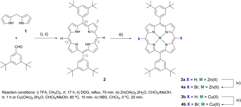
The synthetic strategy to obtain new Zn(II)- and Cu(II)-based porphyrin complexes doubly functionalised with carbazoles 5a and 5b is outlined in Schemes 1 and 2, and it required the previous preparation of starting meso-dibrominated scaffolds 4a and 4b from 5,15-bis(3,5-di-tert-butylphenyl)porphyrin 2. As shown in Scheme 1, porphyrin 2 was obtained in 64% yield by reacting dipyrromethane 1 with 3,5-di-tert-butylbenzaldehyde in the presence of catalytic amounts of trifluoroacetic acid (TFA), followed by oxidation with 2,3-dichloro-5,6-dicyano-1,4-benzoquinone (DDQ).19 Afterwards, metalation of the porphyrin inner core with zinc(II) or copper(II) acetate,20 followed by bromination of both free meso-positions present in complexes 3a or 3b with N-bromosuccinimide (NBS),21 afforded the required derivatives 4a and 4b in 82% and 85% yields, respectively.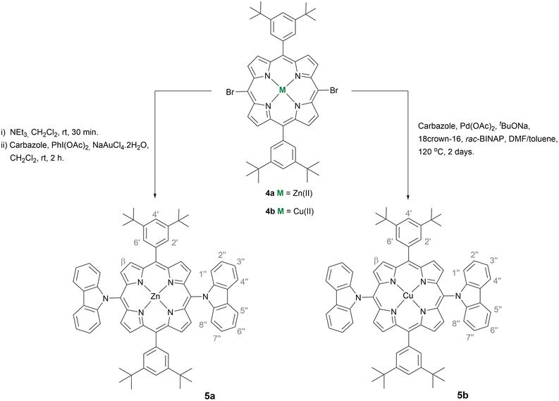 | ||
| Scheme 2 Synthesis of Zn(II) and Cu(II)-based porphyrin complexes doubly functionalised with carbazoles 5a and 5b. | ||
The best protocol to obtain the Zn(II) complex 5a was based on the nucleophilic substitution reaction involving 4a and carbazole mediated by PhI(OAc)2/NaAuCl4·2H2O31 (Scheme 2). This approach was considered after finding that the reaction of the Zn(II) complex 4a with the carbazole using either an Ullmann protocol32 or a Buchwald–Hartwig33 approach led mainly to the exchange of the metal at the inner core by the catalyst metal [Cu(II) or Pd(II)]. To overcome this issue, the coupling of the carbazole with the Ni(II) complex of 5,15-dibromo-10,20-bis(3,5-di-tert-butylphenyl)porphyrin was also performed under Ullmann conditions to afford the desired Ni(II) derivative bearing two carbazole units in 50% yield. However, all subsequent attempts to remove Ni(II) under different acidic conditions, and then to introduce a Zn(II) or Cu(II) ion, led to degradation of the porphyrin and made this approach impractical. In contrast, when the double nucleophilic substitution of 4a with a carbazole (5 equiv.) was carried out in the presence of PhI(OAc)2 (1 equiv.) and NaAuCl4·2H2O (1.5 equiv.) in CH2Cl2 at room temperature, the desired product 5a was isolated in 22% yield accompanied by the corresponding free-base in analogous amounts. Further metalation of the free-base with Zn(AcO)2 allowed to isolate 5a in a total yield of 59%.
To overcome this entire demetallation/metalation process and build up a straight synthetic route, treatment of the dibrominated porphyrin 4a dissolved in CH2Cl2 with triethylamine followed by solvent removal was carried out before the oxidative nucleophilic substitution step. Compound 5a was then isolated in an overall yield of 51%.
When the nucleophilic substitution approach was extended to the Cu(II) complex 4b, the desired derivative 5b was just obtained in 11% yield. However, as the exchange of the Cu(II) ion is less probable due to the higher stability of the porphyrinic complex 4b, the aforementioned Ullmann and Buchwald–Hartwig cross-couplings were again considered (see Table S1†). Under Ullmann conditions, the coupling of 4b with carbazole (10 equiv.) in the presence of N-phenylbenzohydrazide (0.4 equiv.), CuI (0.2 equiv.), and Cs2CO3 (4 equiv.) was carried out in dimethylsulfoxide (DMSO) at 120 °C for 5 days to afford the desired derivative 5b in 31% yield. Considering the Buchwald conditions [carbazole (20 equiv.), Pd(OAc)2 (0.4 equiv.), tBuONa (71 equiv.), 18-crown-6 (0.3 equiv.), and rac-BINAP (0.6 equiv.), at 120 °C in a mixture of N,N′-dimethylformamide and toluene (1![[thin space (1/6-em)]](https://www.rsc.org/images/entities/char_2009.gif) :
:![[thin space (1/6-em)]](https://www.rsc.org/images/entities/char_2009.gif) 2)], the yield of 5b was improved to 39% with the reaction time reduced to 2 days. It is worth referring that the desired product was not obtained when the reaction was carried out in tetrahydrofuran; the most common solvents referred to in couplings involve porphyrins.33b,34
2)], the yield of 5b was improved to 39% with the reaction time reduced to 2 days. It is worth referring that the desired product was not obtained when the reaction was carried out in tetrahydrofuran; the most common solvents referred to in couplings involve porphyrins.33b,34
3.2. Structural characterisation
Structural elucidation of the free-base scaffold 2 and all the Zn(II) complexes described above involved the use of 1D (1H and 13C) and 2D [(1H,1H) COSY, NOESY, (1H,13C) HSQC, and (1H,13C) HMBC] NMR techniques (Fig. S3, S5, S10, and S14–S18†). The 1H-NMR spectrum of the Zn(II) complex 3a, when compared to compound 2, showed the absence of the signal corresponding to the resonance of the inner core NH protons (δ −3.02 ppm). No noticeable change was observed for the resonances of the remaining protons. In 4a, the absence of the singlet at δ 10.3 ppm corresponding to the resonance of the protons at meso-positions confirmed the success of the dibromination step. When compared to the precursor, the presence of the two bromine atoms induced a deshielding of the doublet generated by the resonances of four β-pyrrolic protons from δ 9.46 to 9.62 ppm, whilst the remaining signals were slightly shifted to the high field.After the introduction of the carbazole moieties, compound 5a, the two doublets generated by the resonances of the β-pyrrolic protons were shielded from δ 9.62 and 8.88 ppm to δ 8.88 and 8.58 ppm, respectively. In the aromatic region, four signals appeared ranging from ca. δ 8.5 ppm to ca. δ 6.8 ppm and correspond to the resonance of the carbazole protons.
The singlet due to the resonances of the methyl protons from the 3,5-di-tert-butylphenyl substituents remained almost unchanged, exhibiting a chemical shift around δ 1.5 ppm.
The structures of all Zn(II) and Cu(II) porphyrin complexes were also supported by mass spectrometry (MS-ESI/HRMS-ESI) and UV-Vis spectroscopy. Apart from compound 4b, which displayed the m/z signal corresponding to the [M + 2H]+˙ ion, all the remaining compounds showed the presence of the peak with m/z corresponding to the [M]+˙ or [M + H]+ ion (Fig. S4, S6–S9, S11–S13, and S19–S22†). As expected, both Zn(II) and Cu(II) porphyrin complexes 3a and 3b exhibited typical absorption features of metallo complexes of arylporphyrins with a Soret band assigned to allowed S0 → S2 transitions and two Q bands due to S0 → S1 transitions (Fig. S23†).35 Bromination of the meso-positions induced a red-shift (ca. 18 nm) of the Soret band (compounds 4a and 4b), while a slight blue-shift (ca. 4 nm) was observed after their replacement by carbazole moieties (compounds 5a and 5b). Also, in the Q band region, significant changes were observed after the bromination by a red-shift ranging from 20 to 27 nm, and a less noticeable blue-shift after insertion of the carbazole units (3 to 11 nm). Spin-coated films of 5a and 5b on glass substrates exhibited similar absorption spectra to those in solution with a slight blue-shift of the Soret and Q bands (ca. 10 nm) for Zn(II) complex 5a relatively to complex 5b (Fig. S24†).
3.3. Photovoltaic performance
To assess the performance of the synthesised porphyrins as HTMs, n–i–p PSCs were fabricated. A triple cation Cs+/CH3NH3+/CH(NH2)2+ perovskite was applied onto a TiO2 mesoporous layer on top of an electron extraction layer.29 The porphyrin was then applied as the HTM, over the perovskite layer, and, finally, a thin gold film was deposited to serve as a counter-electrode. For comparison purposes reference cells made of spiro-OMeTAD were used. Lithium bis(trifluoromethylsulphonyl)imide (LiTFSI), tris(2-(1H-pyrazol-1-yl)-4-tert-butylpyridine)cobalt(III) tri[bis(trifluoromethane)sulfonimide] (FK209) dopants and the 4-tert-butylpyridine (TBP) additive were tested to improve the electric conductivity of the HTM layer, either based on the prepared porphyrins or spiro-OMeTAD.The reference cell, loaded with a HTM layer of spiro-OMeTAD doped with composition A – see Table 1, displayed a typical PCE value of 14.74%, with a short-circuit current density (Jsc) of 20.08 mA cm−2, an open-circuit voltage (Voc) of 1.00 V, and a fill factor (FF) of 0.72. It is widely accepted that by reducing Co(III) – present in FK209 – to Co(II), spiro-OMeTAD becomes partially oxidised, rendering the HTM layer more electrically conductive. A cell without FK209 (composition B) displayed a FF of 0.58 and a PCE of 6.01%, similar to the performance of an additive-free cell (composition C), but a much lower Jsc of only 7.90 mA cm−2. To further increase the electrical conductivity of the HTM layer, the hygroscopic co-dopant LiTFSI can be added. Indeed, in the absence of LiTFSI, the devices showed much lower photovoltaic parameters and a PCE < 4% (composition D). However, due to the hygroscopic nature of this additive, the stability of as-prepared cells can also be compromised by water absorption during their preparation and under operation.6,7
| HTM | Compositiona | J sc (mA cm−2) | V oc (V) | FF | PCE (%) |
|---|---|---|---|---|---|
| a A: 0.5 equiv. of LiTFSI, 0.03 equiv. of FK209, and 3.3 equiv. of TBP per mol of HTM; B: 0.5 equiv. of LiTFSI and 3.3 equiv. of TBP per mol of HTM; C: no additives were used; D: 0.03 equiv. of FK209 and 3.3 equiv. of TBP per mol of HTM. | |||||
| spiro-OMeTAD | A | 20.8 | 1.00 | 0.72 | 14.71 |
| B | 7.90 | 0.97 | 0.58 | 6.01 | |
| C | 13.16 | 0.78 | 0.59 | 6.14 | |
| D | 7.51 | 0.81 | 0.54 | 3.33 | |
| 3b | A | 10.09 | 0.85 | 0.62 | 5.30 |
| B | 10.45 | 0.79 | 0.51 | 4.26 | |
| C | 5.39 | 0.76 | 0.56 | 2.30 | |
The role of the HTM additives was also assessed for devices loaded with the meso-unsubstituted Cu(II) porphyrin complex 3b (Table 1). When the 3b HTM was applied without any dopant, the PCE of the corresponding device remained low, with a value of 2.30%. However, when 0.5 equiv. of LiTFSI with 0.05 equiv. of FK209 and 3.3 equiv. of TBP per mol of HTM was added – optimised composition, the PCE increased to 5.30%. In contrast, the absence of FK209 led to devices with a PCE of 4.26%. It is worth noting that the 10,20-unsubstituted porphyrinic system was selected to eliminate any effect of the substituents at this stage. Subsequently, under this optimised additive composition, the role of the Zn(II) complex 3a and also the corresponding Ni(II) and Pd(II) complexes were evaluated (Table S2 in the ESI†). It was found that 3a gave rise to a slightly higher PCE of 6.39%, whilst Ni(II) and Pd(II) complexes resulted in devices with a low PCE of <3%. The last result can be assigned to a poor alignment of the HTM HOMO level with the valence band of the perovskite layer, compared with Cu(II)- and Zn(II)-based porphyrinic HTMs.14,36
The study proceeded then to Zn(II) and Cu(II)-based porphyrins 5a and 5b doubly functionalised with the carbazole. To the best of our knowledge, no C–N direct bond design in porphyrins has been previously reported as HTMs for PSCs. Only, Pozzi and Nazeeruddin described a Zn(II)-phthalocyanine as a mixture of positional isomers reaching a PCE of 6.65% (vs. a spiro-OMeTAD-based device achieving 16.78%).17
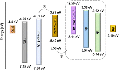
The feasibility of hole extraction of 5a and 5b was evaluated using cyclic voltammetry (CV) – Fig. 1. The HOMO energy levels were estimated from the onset potential of oxidation (Eon Ox), assuming the formal potential of the Fc+/Fc redox couple as −5.1 eV on the Fermi scale.22 The LUMO was obtained by adding E0–0 = 1240/λint (determined from the interception of the normalised absorption and emission spectra, see Fig. S25†). The obtained data are presented in Table 2, together with the HOMO level of spiro-OMeTAD also determined experimentally. As shown in Fig. 2, the HOMO level of spiro-OMeTAD, −5.11 eV, and of the Zn(II) complex 5a, −5.54 eV, have favourable energy alignment with the perovskite layer (ranging from −5.40 eV to −5.50 eV)37 and is expected to lead to higher Voc and Jsc. The deeper HOMO level of the Cu(II) complex 5b, −5.74 eV, must hinder the transportation of holes, leading to lower efficiencies. At the same time, the LUMO levels of both 5a (−3.38 eV) and 5b (−3.62 eV) are higher than that of the perovskite (−3.8 eV), which must block the electron transport to the Au counter-electrode, hence suppressing the carrier recombination.
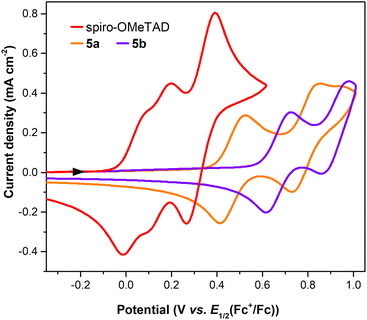 | ||
Fig. 1 Cyclic voltammograms obtained on a GC electrode in a 3![[thin space (1/6-em)]](https://www.rsc.org/images/entities/char_2009.gif) : :![[thin space (1/6-em)]](https://www.rsc.org/images/entities/char_2009.gif) 1 volume ratio of a chlorobenzene 1 volume ratio of a chlorobenzene![[thin space (1/6-em)]](https://www.rsc.org/images/entities/char_2009.gif) : :![[thin space (1/6-em)]](https://www.rsc.org/images/entities/char_2009.gif) acetonitrile mixture of spiro-OMeTAD and porphyrins 5a and 5b. acetonitrile mixture of spiro-OMeTAD and porphyrins 5a and 5b. | ||
| HTM | E on Ox (V) |
λ
int![[thin space (1/6-em)]](https://www.rsc.org/images/entities/char_2009.gif) a (nm) a (nm) |
E
0–0![[thin space (1/6-em)]](https://www.rsc.org/images/entities/char_2009.gif) b b |
E
HOMO![[thin space (1/6-em)]](https://www.rsc.org/images/entities/char_2009.gif) c (eV) c (eV) |
E
LUMO![[thin space (1/6-em)]](https://www.rsc.org/images/entities/char_2009.gif) d (eV) d (eV) |
|---|---|---|---|---|---|
a Determined from the interception of the normalised absorption and emission spectra in a 3![[thin space (1/6-em)]](https://www.rsc.org/images/entities/char_2009.gif) : :![[thin space (1/6-em)]](https://www.rsc.org/images/entities/char_2009.gif) 1 volume ratio of the chlorobenzene 1 volume ratio of the chlorobenzene![[thin space (1/6-em)]](https://www.rsc.org/images/entities/char_2009.gif) : :![[thin space (1/6-em)]](https://www.rsc.org/images/entities/char_2009.gif) acetonitrile mixture.
b
E
0–0 = 1240/λint.
c
E
HOMO = −(5.1 + Eon Ox + 0.042).
d
E
LUMO = EHOMO + E0–0.
e The ELUMO from spiro-OMeTAD is described in the literature.38 acetonitrile mixture.
b
E
0–0 = 1240/λint.
c
E
HOMO = −(5.1 + Eon Ox + 0.042).
d
E
LUMO = EHOMO + E0–0.
e The ELUMO from spiro-OMeTAD is described in the literature.38
|
|||||
| spiro-OMeTAD | −0.33 | n.d. | n.d. | −5.11 | −2.50e |
| 5a | +0.39 | 574.7 | 2.16 | −5.54 | −3.38 |
| 5b | +0.60 | 585.9 | 2.12 | −5.74 | 3.62 |
The optimised geometry and molecular orbitals of 5a and 5b using the B3PW91/LANDL2DZ level of theory are shown in Fig. 3 and also indicate the higher potential of the Zn(II) complex as the HTM. For this complex the HOMO electron density distribution is mainly localised at the porphyrin core and at the twisted carbazole units, while for the Cu(II) complex 5b it is mainly delocalised over the whole molecule.
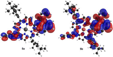 | ||
| Fig. 3 Density of HOMO frontier molecular orbitals for the optimised geometries of porphyrins 5a and 5b. The represented isosurface has a value of 0.0148. | ||
The performance of porphyrins 5a and 5b as HTMs was evaluated under the optimised conditions previously established for the meso-unsubstituted complexes 3. Fig. 4 shows the current density–potential difference (J–V) curves of devices with 5a and 5b HTMs; the corresponding photovoltaic characteristics are presented in Table 3. As expected, this strong π-donor group directly connected to the macrocycle produces drastic changes. An improved FF of 0.73 for 5a and 5b (vs. 0.69 for 3a and 0.62 for 3b) and Jsc values of 13.79 and 9.14 mA cm−2 for 5a and 5b, respectively, were recorded. Although significantly lower than those of the spiro-OMeTAD reference cell (ca. 14.7%), these devices displayed a PCE of 9.87% for 5a and 6.37% for 5b. These photovoltaic performances are substantially higher than those achieved with unsubstituted porphyrins 3a (PCE = 6.3%) and 3b (PCE = 5.30%), and higher than Zn(II)-phthalocyanine,17 pointing out also the critical role of the metallic Zn(II) centre in comparison with Cu(II).
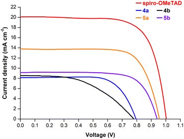 | ||
| Fig. 4 J–V curves under simulated 1-sun illumination (AM1.5G) of perovskite solar cells using spiro-OMeTAD and porphyrins 4a, 4b, 5a, and 5b as the hole-transporting layer. | ||
| HTM | J sc (mA cm−2) | V oc (V) | FF | PCE (%) |
|---|---|---|---|---|
| a The HTM precursor solution was prepared considering 0.5 equiv. of LiTFSI, 0.03 equiv. of FK209, and 3.3 equiv. of TBP per mol of HTM. | ||||
| 4a | 8.15 | 0.79 | 0.71 | 4.68 |
| 4b | 8.58 | 0.77 | 0.49 | 3.31 |
| 5a | 13.79 | 0.96 | 0.73 | 9.87 |
| 5b | 9.14 | 0.94 | 0.73 | 6.37 |
To gain insight into the role of electron-withdrawing substituents in cell performance, dibrominated porphyrins 4a and 4b were also used as the HTM layer. Fig. 4 displays the J–V curves of these devices, whilst the respective photovoltaic characteristics are shown in Table 3. A PCE of 4.68% and 3.31% was obtained respectively for devices based on 4a and 4b, which are much lower compared to 5a and 5b. In general, halogens, due to their relatively large size, can induce a conformational distortion of the porphyrin core when compared to those caused by other substituent groups.39 However, the superimposed geometries of 3 and 4 indicate almost no difference in the structures when the hydrogen atom is replaced by bromine (Fig. S2†). This points out that the inductive electron-withdrawing character of the bromine atoms has an important contribution to the lower Voc and Jsc values observed for these devices.
To assess the reproducibility of device performance, a batch of 12 individual cells using the Zn(II) porphyrin complexes 3a, 4a, and 5a as HTMs were fabricated (cf. Tables S2–S6 in the ESI†). Fig. 5 shows the statistical data for Jsc, Voc, FF, and PCE, respectively, along with the spiro-OMeTAD reference (vide Table S3†). The performance of prepared devices follows the sequence 4a < 3a < 5a for all parameters except for the FF, where 3a HTM-based devices display the lowest value. This was assigned to the high solubility of the perovskite in most solvents, and only a few non-polar solvents could be used in HTM deposition, such as benzene (highly toxic), chlorobenzene, or toluene. Porphyrin 3a is highly soluble in N,N′-dimethylformamide, but poorly soluble in chlorobenzene or toluene. Therefore, the spin-coating deposition process results in a more irregular distribution of the HTM layer and less intimate contact with the perovskite, which may explain the lower mean FF value and higher standard deviation compared to devices based on 4a and 5a. Generally, the 4a < 3a < 5a sequence is fully in line with the evolution of electron-withdrawing substituents – bromine groups, to those with an electron-donor character – carbazole units.
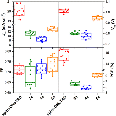 | ||
| Fig. 5 Statistics of 12 individual PSC devices with the hole-transporting layer made of spiro-OMeTAD and porphyrins 3a, 4a, and 5a. | ||
The PCE histograms are plotted in Fig. 6 showing good reproducibility of the PSCs using porphyrin-based HTMs.
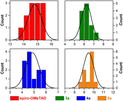 | ||
| Fig. 6 Histogram data of PCE for 12 individual PSC devices with a hole-transporting layer made of spiro-OMeTAD and porphyrins 3a, 4a, and 5a. | ||
Indeed, more than 60% of 5a-based devices exhibited efficiencies superior to 9.3%, and the best-performing cell reached a PCE of 10.01%, which is 65% of the PCE displayed by the spiro-OMETAD reference. Moreover, 5a-based devices show a remarkably narrower PCE distribution.
These results confirm that the use of porphyrin 5a provides better performance and, most relevantly, a substantial enhancement in reproducibility, a very relevant characteristic when aiming at the development of devices with potential commercial interest.
3.4. Photoluminescence analysis
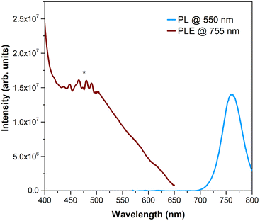
To better understand the quality of the perovskite/HTM interface, steady-state photoluminescence (PL) and photoluminescence excitation (PLE) studies were performed. Firstly, the PL emission of the perovskite film on TiO2/glass substrates was recorded at an excitation wavelength of 550 nm (incidence on the perovskite face), resulting in an emission band with a maximum at ca. 755 nm, as can be seen in Fig. 7. PLE recorded at 755 nm evidenced a tail of absorption whose intensity increases from 650 nm up to 500 nm. In addition, its maximum occurs at the same spectral region where porphyrins typically exhibit the maximum absorption (Fig. S24†). So, Zn(II) and Cu(II) porphyrin complexes 5a and 5b were also studied when deposited as a film on glass substrates. Fig. 8 shows the results of PL, acquired at two different excitation wavelengths, and PLE experiments performed on 5a when irradiating at the porphyrin side. The selected excitation wavelengths correspond to a maximum (420 nm) and a minimum (500 nm) of the PLE spectrum. Both PL spectra exhibit two maxima at 621 and 676 nm. Furthermore, the PLE recorded at 676 nm fairly matches the absorption spectrum previously observed in UV-Vis spectra (Fig. S24†). In the case of 5b, no emission could be detected due to the poor film quality. Hence, for comparison purposes, the powders of both samples were analysed (Fig. S26†). Indeed, both emit within the same spectral region of the PL band of the perovskite, particularly 5b.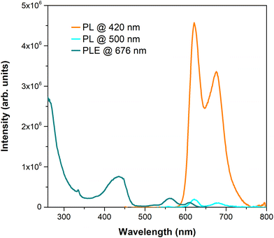 | ||
| Fig. 8 Photoluminescence spectrum acquired at different excitation wavelengths and photoluminescence excitation spectrum of porphyrin 5a deposited as a film on a glass substrate (λem = 676 nm). | ||
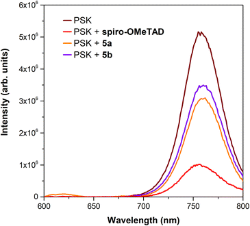
Further PL analysis was performed in perovskite-HTM films based on porphyrins 5a and 5b and spiro-OMeTAD, as depicted in Fig. 9, to assess the role of the HTM in the perovskite PL recombination. The photoincidence is now placed on the glass surface as for device characterisation. Moreover, in this way, it is ensured that the interfaces are the same either in the absence or the presence of the HTM, minimising possible phenomena related to different light absorption from the HTM layers studied. It was observed that the PL intensity decreased when both porphyrin-based HTMs were used, being the higher effect observed for 5a. However, the strongest decrease was observed for spiro-OMeTAD. A reproducible behaviour was observed regardless of the excitation wavelength used (Fig. S27†), though with distinct relative PL emission intensities. Indeed, this decrease in PL intensity is in good agreement with the behaviour of the J–V curves depicted in Fig. 4. These results indicate hole extraction and transfer from the perovskite to the HTM layer, which is in line with the estimated HOMO energy alignment (Fig. 2). Nonetheless, the non-negligible contribution from the porphyrin PL emission can play a role in PL spectra as their emission occurs in the same spectral regions as the perovskite. Accordingly, the contribution of the porphyrin PL signal to the overall spectrum may account for a lower PL intensity reduction when compared to spiro-OMeTAD. Therefore, a direct association between the PL intensity and the charge transfer phenomenon is not straightforward. As a result of this investigation, it becomes evident how important it is to control the optical response of the HTM layer to infer the charge dynamics of hole extraction and transport.
4. Conclusions
A series of Zn(II) and Cu(II)-based porphyrins doubly functionalised with a carbazole were successfully synthesised and used as HTMs in PSC devices. The Cu(II) complex was properly obtained by C–N transition metal-assisted couplings involving the dibrominated porphyrin precursor. Nevertheless, the Zn(II) complex, due to the metal exchangeability and lability behaviour, led to the use of a nucleophilic substitution protocol. Cyclic voltammetry experiments showed the best alignment of the HOMO energy level of the Zn(II) complex 5a with the perovskite valence band. The optimised geometry and molecular orbitals of both complexes also corroborate the higher potential of 5a as the HTM. Photoluminescence studies showed emission quenching, compatible with the hole transfer phenomenon. Photovoltaic devices fabricated with a 5a-based HTM layer displayed a reproducible maximum power conversion efficiency of ca. 10%.These results are the first example of the use of direct C–N linkage involving porphyrins in the preparation of HTMs, and with significantly higher PCEs compared to previously reported devices based on a phthalocyanine analogue, which displayed a PCE of 6.65%. Furthermore, this work highlights the influence of the metal present in the porphyrin cavity, as well as the nature of the substituents on the PCE displayed by the resulting devices.
Author contributions
Melani J. A. Reis: methodology, investigation, formal analysis, and writing – original draft. Ana T. Nogueira: methodology, investigation, and formal analysis. Ana Eulálio: methodology, investigation, formal analysis, and writing – original draft. Nuno M. M. Moura: supervision, conceptualisation, methodology, investigation, formal analysis, and writing – original draft. Joana Rodrigues: methodology, investigation, formal analysis, and writing – original draft. Dzmitry Ivanou: methodology, investigation, formal analysis, and writing – original draft. Paulo E. Abreu: methodology, investigation, formal analysis, and writing – original draft. M. Rosário P. Correia: methodology, investigation, formal analysis, and writing – original draft. Maria G. P. M. S. Neves: supervision, conceptualisation, and writing – original draft. Ana M. V. M. Pereira: funding acquisition, supervision, conceptualisation, methodology, investigation, formal analysis, and writing – original draft. Adélio Mendes: funding acquisition, supervision, conceptualisation, and writing – original draft.Conflicts of interest
There are no conflicts to declare.Acknowledgements
The authors thank the University of Aveiro, the University of Porto, and the University of Coimbra. This work was financially supported by UIDB/50006/2020 and UIDP/50006/2020 (LAQV-REQUIMTE), LA/P/0045/2020 (ALiCE), UIDB/00511/2020 and UIDP/00511/2020 (LEPABE), UIDB/50025/2020, UIDP/50025/2020, and LA/P/0037/2020 (i3N), UID/QUI/00313/2020 (Coimbra Chemistry Centre), and Infrastructure Project No. 022161 – the Research Units and Portuguese NMR Network, funded by national funds through FCT/MCTES (PIDDAC); Project FCT POCI-01-0145-FEDER-030357 – “Taylor made porphyrinoids for emerging efficient solar energy devices”, funded by FEDER funds through COMPETE2020 – Programa Operacional Competitividade e Internacionalização (POCI) and by national funds (PIDDAC) through FCT/MCTES. M. J. A. Reis (2020.05838.BD), A. T. Nogueira, A. Eulálio, N. M. M. Moura (CDL-CTTRI-048-88-ARH/2018) and A. M. V. M. Pereira thanked FCT and the projects POCI-01-0145-FEDER-030357 and PTD/EQU-EQU/4225/2021 for the research contracts and concession agreements. J. Rodrigues also acknowledges FCT for Programme Stimulus of Scientific Employment – Individual Support (2022.00010.CEECIND).References
- J. Nelson, The Physics of Solar Cells, Imperial College Press, London, 2003 Search PubMed.
- (a) C. Battaglia, A. Cuevas and S. De Wolf, Energy Environ. Sci., 2016, 9, 1552 RSC; (b) M. Okil, T. M. Abdolkader and A. Shaker, Silicon, 2022, 14, 1895 CrossRef CAS; (c) https://www.nrel.gov/pv/assets/pdfs/best-research-cell-efficiencies-rev220630.pdf (accessed June 2023).
- A. K. Jena, A. Kulkarni and T. Miyasaka, Chem. Rev., 2019, 119, 3036 CrossRef CAS PubMed.
- J. Y. Kim, J.-W. Lee, H. S. Jung, H. Shin and N.-G. Park, Chem. Rev., 2020, 120, 7867 CrossRef CAS PubMed.
- A. Kojima, K. Teshima, Y. Shirai and T. Miyasaka, J. Am. Chem. Soc., 2009, 131, 6050 CrossRef CAS PubMed.
- J. Urieta-Mora, I. García-Benito, A. Molina-Ontoria and N. Martín, Chem. Soc. Rev., 2018, 47, 8541 RSC.
- G.-W. Kim, H. Choi, M. Kim, J. Lee, S. Y. Son and T. Park, Adv. Energy Mater., 2020, 10, 1903403 CrossRef CAS.
- C. Lu, I. T. Choi, J. Kim and H. K. Kim, J. Mater. Chem. A, 2017, 5, 20263 RSC.
- X. Liu, S. Ma, M. Mateen, P. Shi, C. Liu, Y. Ding, M. Cai, M. Guli, M. K. Nazeeruddin and S. Dai, Sustainable Energy Fuels, 2020, 4, 1875 RSC.
- X. Li, N. Sun, Z. Li, J. Chen, Q. Sun, H. Wang and Y. Hao, New J. Chem., 2021, 45, 735 RSC.
- M. Urbani, G. de la Torre, M. K. Nazeeruddin and T. Torres, Chem. Soc. Rev., 2019, 48, 2738 RSC.
- Y. Matsuo, K. Ogumi, I. Jeon, H. Wang and T. Nakagawa, RSC Adv., 2020, 10, 32678 RSC.
- H.-H. Chou, H.-Y. Chiang, M.-H. Li, P.-S. Shen, H.-J. Wei, C.-L. Mai, P. Chen and C.-Y. Yeh, ACS Energy Lett., 2016, 1, 956 CrossRef CAS.
- S. Chen, P. Liu, Y. Hua, Y. Li, L. Kloo, X. Wang, B. Ong, W.-K. Wong and X. Zhu, ACS Appl. Mater. Interfaces, 2017, 9, 13231 CrossRef CAS PubMed.
- R. Azmi, U.-H. Lee, F. T. A. Wibowo, S. H. Eom, S. C. Yoon, S.-Y. Jang and I. H. Jung, ACS Appl. Mater. Interfaces, 2018, 10, 35404 CrossRef CAS PubMed.
- Y.-H. Chiang, H.-H. Chou, W.-T. Cheng, Y.-R. Li, C.-Y. Yeh and P. Chen, ACS Energy Lett., 2018, 3, 1620 CrossRef CAS.
- K. T. Cho, K. Rakstys, M. Cavazzini, S. Orlandi, G. Pozzi and M. K. Nazeeruddin, Nano Energy, 2016, 30, 853 CrossRef CAS.
- N. Fukui, W.-Y. Cha, S. Lee, S. Tokuji, D. Kim, H. Yorimitsu and A. Osuka, Angew. Chem., Int. Ed., 2013, 52, 9728 CrossRef CAS PubMed.
- C. Brückner, J. J. Posakony, C. K. Johnson, R. W. Boyle, B. R. James and D. Dolphin, J. Porphyrins Phthalocyanines, 1998, 2, 455 CrossRef.
- J. W. Buchler, in Porphyrins and Metalloporphyrins, ed. K. M. Smith, Elsevier, Amsterdam, 1975, ch. 5, p. 157 Search PubMed.
- S. G. DiMagno, V. S. Y. Lin and J. M. Therien, J. Org. Chem., 1993, 58, 5983 CrossRef CAS.
- C. M. Cardona, W. Li, A. E. Kaifer, D. Stockdale and G. C. Bazan, Adv. Mater., 2011, 23, 2367 CrossRef CAS PubMed.
- G. M. J. Barca, C. Bertoni, L. Carrington, D. Datta, N. De Silva, J. E. Deustua, D. G. Fedorov, J. R. Gour, A. O. Gunina, E. Guidez, T. Harville, S. Irle, J. Ivanic, K. Kowalski, S. S. Leang, H. Li, W. Li, J. J. Lutz, I. Magoulas, J. Mato, V. Mironov, H. Nakata, B. Q. Pham, P. Piecuch, D. Poole, S. R. Pruitt, A. P. Rendell, L. B. Roskop, K. Ruedenberg, T. Sattasathuchana, M. W. Schmidt, J. Shen, L. Slipchenko, M. Sosonkina, V. Sundriyal, A. Tiwari, J. L. G. Vallejo, B. Westheimer, M. Włoch, P. Xu, F. Zahariev and M. S. Gordon, J. Chem. Phys., 2020, 152, 154102 CrossRef CAS PubMed.
- A. D. Becke, J. Chem. Phys., 1993, 98, 5648 CrossRef CAS.
- P. J. Hay and W. R. Wadt, J. Chem. Phys., 1985, 82, 299 CrossRef CAS.
- B. P. Pritchard, D. Altarawy, B. Didier, T. D. Gibson and T. L. Windus, J. Chem. Inf. Model., 2019, 59, 4814 CrossRef CAS PubMed.
- C. J. Cramer and D. G. Truhlar, Phys. Chem. Chem. Phys., 2009, 11, 10757 RSC.
- M. Aydin, D. L. Akins, M. Aydin and D. L. Akins, in Applications of Molecular Spectroscopy to Current Research in the Chemical and Biological Sciences, IntechOpen, 2016 Search PubMed.
- M. Saliba, T. Matsui, J.-Y. Seo, K. Domanski, J.-P. Correa-Baena, M. K. Nazeeruddin, S. M. Zakeeruddin, W. Tress, A. Abate, A. Hagfeldt and M. Grätzel, Energy Environ. Sci., 2016, 9, 1989 RSC.
- I. Mesquita, L. Andrade and A. Mendes, ChemSusChem, 2019, 12, 2186 CrossRef CAS PubMed.
- D.-M. Shen, C. Liu, X.-G. Chen and Q.-Y. Chen, J. Org. Chem., 2009, 74, 206 CrossRef CAS PubMed.
- J. Haumesser, A. M. V. M. Pereira, J.-P. Gisselbrecht, K. Merahi, S. Choua, J. Weiss, J. A. S. Cavaleiro and R. Ruppert, Org. Lett., 2013, 15, 6282 CrossRef CAS PubMed.
- (a) A. M. V. M. Pereira, M. G. P. M. S. Neves, J. A. S. Cavaleiro, C. Jeandon, J.-P. Gisselbrecht, S. Choua and R. Ruppert, Org. Lett., 2011, 13, 4742 CrossRef CAS PubMed; (b) A. Nowak-Król and D. T. Gryko, Org. Lett., 2013, 15, 5618 CrossRef PubMed.
- (a) T. Takanami, M. Hayashi, F. Hino and K. Suda, Tetrahedron Lett., 2003, 44, 7353 CrossRef CAS; (b) Y. Chen and X. P. Zhang, J. Org. Chem., 2003, 68, 4432 CrossRef CAS PubMed.
- M. Gouterman, J. Mol. Spectrosc., 1961, 6, 138 CrossRef CAS.
- C.-G. Si, X.-D. Lv and S.-J. Long, Inorg. Chem. Commun., 2020, 112, 107701 CrossRef CAS.
- M. Deepa, M. Salado, L. Calio, S. Kazim, S. M. Shivaprasad and S. Ahmad, Phys. Chem. Chem. Phys., 2017, 19, 4069 RSC.
- L. Nakka, Y. Cheng, A. G. Aberle and F. Lin, Adv. Energy Sustainability, 2022, 3, 2200045 CrossRef CAS.
- K. J. Flanagan, M. P. Dominguez, Z. Melissari, H.-G. Eckhardt, R. M. Williams, D. Gibbons, C. Prior, G. M. Locke, A. Meindl, A. A. Ryan and M. O. Senge, J. Org. Chem., 2021, 17, 1149 CAS.
Footnotes |
| † Electronic supplementary information (ESI) available: Experimental section and characterisation data. See DOI: https://doi.org/10.1039/d3dt00512g |
| ‡ These authors contributed equally to this work. |
| This journal is © The Royal Society of Chemistry 2023 |

