
 Open Access Article
 This Open Access Article is licensed under a
 Creative Commons Attribution 3.0 Unported Licence
Synthesis of highly-uniform titania overcoats on a mesoporous alumina catalyst support by atomic layer deposition and their application in hydroprocessing†
Jacob A.
Moulijn
 *ab,
J. Ruud
van Ommen
b,
Aristeidis
Goulas
b,
David
Valdesueiro
b,
Jana
Juan-Alcañiz
c,
Kar-Ming
Au-Yeung
c,
Leo
Woning
c and
Jaap A.
Bergwerff
c
*ab,
J. Ruud
van Ommen
b,
Aristeidis
Goulas
b,
David
Valdesueiro
b,
Jana
Juan-Alcañiz
c,
Kar-Ming
Au-Yeung
c,
Leo
Woning
c and
Jaap A.
Bergwerff
c
aDelft IMP B.V, Molengraaffsingel 8, 2629 JD Delft, The Netherlands
bDelft University of Technology, van der Maasweg 9, 2629 HZ Delft, The Netherlands
cKetjen, Nieuwendammerkade 1-3, 1022 AB Amsterdam, The Netherlands
First published on 23rd May 2023
Abstract
The feasibility of gas phase deposition using a Ti alkoxide precursor for precise surface modification of catalysts was demonstrated by modifying a mesoporous alumina support with a Ti oxide overcoat. Titanium tetra-isopropoxide yields a Ti oxide layer that covers homogeneously the alumina surface. Uniformity of the deposited TiO2 was verified by SEM-EDX, on both intra-particle and inter-particle levels. Only a few atomic layer deposition (ALD) cycles were required in order to obtain Ti contents with a relevance for industrial application. The pore size distribution of the overcoated catalyst support was barely affected by the coating process. Synthesized CoMo catalysts based on the Ti-alumina carrier showed up to 40% higher activity compared to a catalyst supported on pristine alumina, in hydroprocessing under industrial testing conditions. The TiO2 coating appeared to be stable, showing no agglomeration characteristics after reaction as corroborated by TEM-EDX. ALD provides a scalable route with low waste generation for the production of precisely structured TiO2–Al2O3 hydroprocessing catalyst supports.
Introduction
Hydroprocessing catalysts play a central role in oil refineries as they enable the reduction of the sulphur and nitrogen content of the refining products. Also, in the production of fuels from biogenic sources and the refining of waste recycle streams, hydroprocessing catalysts hold an important contribution. Typical catalyst materials are combinations of molybdenum or tungsten oxide, promoted by cobalt or nickel oxide and supported on a porous carrier, often alumina (Al2O3).1–3 Following increasingly stringent environmental regulations, there are continuous initiatives for research of more active catalysts. Titanium oxide (TiO2) has emerged as a promising support, outperforming alumina.4–9 It has been shown that the interaction of the active phase and the support is lower for TiO2 than for Al2O3.10 As such, this reduced interaction can explain the higher activity of TiO2-based catalysts. Another explanation put forward by Coulier et al.11 has shown that TiO2 sites act as promotor sites, similar to Ni and Co.Unfortunately, compared to aluminas, titanium oxides generally have small surface areas and a poor thermal stability,12 which negatively affects catalyst performance. The negative effect of the low surface area becomes especially pronounced at the high active metal loadings, which are required for the production of ultra-low-sulphur diesel (ULSD). Thus, it is difficult to assess the true potential of TiO2 as a support for industrial hydroprocessing catalysts. An elegant alternative design proposal involves the modification of a commercially available alumina with favourable porosity characteristics (pore volume, pore size distribution, specific surface area) with a thin overcoat of titanium oxide. In this way, the effect of TiO2 addition to hydroprocessing performance can be assessed without the interfering effect of the pore structure. One of our goals was to provide a fair comparison of titania and alumina for application as support for hydroprocessing catalysts.
Solvent-based methods are conventionally applied in the synthesis of hydroprocessing catalysts. We opted for the use of atomic layer deposition (ALD), a highly precise gas phase deposition technique, in synthesizing a TiO2–Al2O3 support of a high-quality CoMo hydroprocessing catalyst.13–17 The applicability of ALD for the preparation of heterogeneous catalysis and their respective catalytic supports has been discussed extensively in literature.13,18 For hydroprocessing, ALD was successfully implemented for the synthesis of a Pd-based catalyst19 and the modification of a Pd catalyst with a TiO2 overcoat.20 Furthermore, MoO3 active phase growth on mesoporous alumina by ALD and its application in oxidative desulphurization has been reported.21 ALD synthesis was anticipated to lead to a homogeneously distributed Ti layer, fully covering the accessible surface of the support. Moreover, contrary to conventional used synthesis methods it provides the possibility to avoid the use of solvents, thus drastically minimizing the generation of synthesis process-related waste.22
In early ALD studies, Lakomaa et al.23 first reported the growth of a TiO2 oxide coating onto a mesoporous silica catalyst support by TiCl4 and H2O. Haukka et al.24,25 implemented a single TiCl4 exposure on mesoporous SiO2 catalyst support. After thermal decomposition of the deposited species, scanning electron microscopy coupled with energy dispersive X-ray spectroscopy (SEM-EDX) of silica particle cross-sections revealed an even distribution of the TiO2 particles, with no enrichment of the outermost surface of the support.25 In the follow-up work of Lakomaa et al.,26 the homogeneity of the Cr and Ti species spatial distribution was again verified. A high ratio of Cl/Ti was observed in all cases, and residual Cl was only reported to be removable by thermal treatment with H2O vapor at 450 °C.
In addition, Haukka et al.27 described the modification of mesoporous γ-alumina by titanium tetra-isopropoxide (TTIP). Lindblad et al.28 deposited TiO2 into porous Al2O3 using TTIP and air at 450 °C. Keränen et al.29 used TTIP to modify mesoporous SiO2 with TiO2, in order to prepare a catalyst support for subsequent vanadia deposition. Treatment at elevated temperature for the ligand removal was required, similar to the work based on the TiCl4 precursor. Lu et al.30 and Yang et al.31 described the growth of TiO2 into silica gel powder, using TTIP and H2O at lower temperature (150 °C and 200 °C respectively). SEM-EDX revealed that the Ti species were deposited more effectively on the outer surface of the SiO2 support.31
Catalyst performance can be heavily influenced by the existence of impurities that can strongly absorb into the support surface. Such is the case for the Cl ligands of the Ti halide precursor. Although a ligand removal step at high temperature can eliminate the Cl impurities, ALD schemes operated at -relatively- low temperatures are deemed more feasible for large-scale catalyst synthesis. For that reason, we selected the alkoxide precursor, titanium tetra-isopropoxide for our ALD scheme. A comprehensive list of TTIP-based ALD processes for TiO2 growth is reported in the review article of Niemelä et al.32
In summary, the objective of this study was (i) to demonstrate the feasibility of TTIP as ALD precursor for the synthesis of highly-uniform overcoats on mesoporous catalyst supports at deposition temperatures that enable feasible large-scale catalyst synthesis, and (ii) to establish the superior properties of titania compared to alumina as support for hydroprocessing catalysts.
Experimental
Overcoat synthesis by ALD
The coating experiments were carried out in a fluidized bed reactor33 operated at atmospheric pressure. This reactor is composed of a glass column of 26 mm internal diameter and 500 mm height, supported on a pneumatically vibrated piston to assist the fluidization of the powder. Four infrared lamps placed around the column were used to heat up the reactor to the reaction temperature, while a type-K thermocouple inserted inside the column enabled control of the reaction temperature. The fluidization gas was introduced through a stainless-steel SIKA-R 20 distributor plate of sintered particles with a pore size of 37 μm. An identical distributor plate is placed on the top part of the column to prevent entrainment of any particles outside the column due to elutriation.Mesoporous γ-alumina, produced by Ketjen as support for hydroprocessing catalysts, was used as the catalyst support. This material has a monomodal pore size distribution containing mesopores, with 90% of the pore volume corresponding to pore size below 12 nm, and no significant amount of macropores. The specific surface area is 271 m2 g−1, estimated by N2 physisorption. In all experiments the γ-alumina is used as particles at sieve fractions of 125–300 μm, obtained by crushing extrudates, followed by sieving. The precursors used for the deposition of TiO2 were titanium(IV) isopropoxide 98% (Strem Chemicals) and de-mineralized water (Veolia). Both precursors were contained in 600 mL stainless-steel bubblers. The bubbler of TTIP was heated at 90 °C while the water bubbler was kept at room temperature. Pressurized N2 (grade 5.0, Linde Gas) was used as carrier and fluidization gas. In all the experiments the initial mass of Al2O3 powder was 3 g, the flow of N2 was 0.8 l min−1, and the reaction temperature was 180 °C. Before starting the deposition process, the powder was pretreated by heating to the reaction temperature (180 °C) and flushing with N2 for up to 9 h to remove physisorbed water molecules from the surface.
After the ALD process, the samples were further submitted to a mild calcination at 350 °C to ensure removal of any remaining organics and transformation of titanium hydroxide into the respective oxide. Calcination was carried out in a static oven with a ramp rate of 5 °C min−1 and a dwell time of 2 h.
Catalyst characterization
The composition of the coated samples was determined by induced coupled plasma optical emission spectroscopy (ICP-OES) in a Perkin Elmer Optima 3000 DV. Cross-sectional scanning electron microscopy combined with energy dispersive X-ray spectroscopy (SEM-EDX) was used to determine the presence of the coating on the inner pore space and the external surface of the particles in a Zeiss EVO MA15-Noran system 7 microscope. Transmission electron microscopy with energy dispersive X-ray spectroscopy (TEM-EDX) was used to assess the dispersion of the deposited TiO2 overcoat and the CoMo active phase, before and after the catalytic testing. A Tecnai Osiris microscope equipped with a FEG gun was utilized. The porosity characteristics were evaluated by N2 adsorption using the Brunauer–Emmett–Teller (BET) method in a Quantachrome Autosorb-6B surface area analyser. Alternatively, the surface area of the samples was determined by hexane adsorption using a method34 developed by Ketjen. More details can be found in the ESI.†Catalytic testing
The coated TiO2–Al2O3 support powder was impregnated with a CoMo aqueous-based solution and dried at 120 °C in a static oven (details in ESI†). The metal loadings are comparable to that of commercial catalysts. Subsequently, the catalyst performance was determined under industrially relevant hydroprocessing conditions for the production of ultra-low-sulphur diesel. The catalysts were tested in a fixed bed multi-tubular reactor for hydroprocessing performance testing. Catalysts were tested as particles from crushed extrudates, size-selected in the 125–300 μm range. For all catalysts, 0.9 ml of the catalytic material was measured and loaded in the reactor. The catalysts were sulfided in situ with a light gas oil (LGO) feed spiked with dimethyl disulfide (DMDS), resulting in a pre-sulfiding feed with 2.5 wt% S at 320 °C, 45 bar, a liquid hourly space velocity (LHSV) of 3.0 h−1 and a H2/LGO ratio of 300 Nl l−1. The catalysts were exposed to LGO at 45 bar and a H2/LGO ratio 300 Nl l−1 at different feed rates and temperatures, before activity evaluation at 350 °C and a LHSV of 2.0 h−1 took place. To assess the effect of the TiO2 overcoats, catalyst performance of the CoMo/TiO2–Al2O3 catalysts was benchmarked against the performance of a CoMo/Al2O3 catalyst prepared via the same preparation method by using the same pristine mesoporous Al2O3 as the support. The catalyst performance is expressed as the relative volume activity (RVA) and as the activity per Mo atom (RMA) in hydrodesulphurization (HDS). Further details on the testing procedure can be found in the ESI.†Results and discussion
Overcoated catalyst support characterization
In our exploratory studies it was found that a satisfactory TTIP exposure time for achieving surface saturation was 90 min. Samples were therefore prepared at 180 °C with 1, 2 and 3 cycles using the dosing times from the calibration study, i.e., 90–120 – 60–120 min respectively for the exposure of TTIP, purging of TTIP, exposure of H2O and purging of H2O. In each run, 3 g of the alumina substrate were coated in the fluidized bed reactor, while the time for pre-treatment was 9 h to ensure extensive removal of physisorbed water. The bulk Ti loading of the samples was quantified using ICP-OES, SEM-EDX was used to estimate the Ti-distribution over the cross section of the particles (line scans) and of specific areas (spot analysis), i.e., the centre of cross-sectioned particles.The Ti loading of the three samples (Fig. 1) increases linearly with the number of ALD cycles. It should be noted that the bulk Ti concentrations estimated from ICP-OES do not give information on the Ti distribution over the particle surface. From the data in Fig. 1 the growth-per-cycle (GPC) can be estimated. The GPC is the ratio of the volume of TiO2 deposited per cycle and the corresponding surface area. Fig. 1 shows that per cycle ca. 4 wt% Ti is deposited, corresponding with ca. 7 wt% TiO2. The surface area of the alumina used is 271 m2 g−1 and the density of the deposited TiO2 is assumed to be 3.8 g cm−3. We consider 1 g of product, containing 0.93 g of alumina with a surface area of 271 × 0.93 m2 g−1 and 0.07 g of TiO2 with a volume of 0.07/3.8 cm3. The corresponding GPC equals to 0.07 nm. The value of the GPC is approximately double than the GPC of a comparable ALD process that was estimated for Si wafers by ellipsometry.31 For an interpretation of the GPC value it is meaningful to compare it with the GPC value corresponding to a theoretical full coverage of the deposited material, calculated from the stoichiometry of the deposition reaction, taking place as depicted in Scheme 1.35 This scheme shows a stoichiometry of Ti/OH of one to two. For the calculation of a theoretical full coverage with TiO2 the concentration of the OH surface groups should be known. The OH concentration of alumina surfaces has been reported in literature.36,37 It is a strong function of the pretreatment temperature of the alumina. At the temperature of this study, 180 °C, the OH concentration is 10–12 OH/nm2.36 Based on this value, the concentration of TiO2 for the conditions of the ALD synthesis in this study is estimated to be 5–6 TiO2 species per nm2 alumina. The surface area of the alumina is 271 m2 g−1. From these data the TiO2 concentration per g of alumina at full coverage is calculated to be 1.36 × 10²¹ to 1.63 × 10²¹ TiO2 species per g alumina, corresponding with a TiO2 content of 18–21.5 wt% on the alumina basis. The value of the mass fraction of TiO2 per unit mass of product can be calculated according to the relationship depicted in Scheme 2. The resulting value for the theoretical full coverage with TiO2 is 15–18 wt%.
 | ||
| Fig. 1 Titanium content (bulk, measured by ICP-OES) of the samples overcoated with 1, 2 and 3 TTIP ALD cycles. The line indicates a linear fit. | ||
 | ||
| Scheme 1 Simplified interaction of a hydroxylated alumina surface with TTIP and H2O during the ALD overcoating reactions. | ||
 | ||
| Scheme 2 Conversion of TiO2 concentration per g of alumina at full coverage, to TiO2 concentration per g of overcoated catalyst support product. | ||
As shown in Fig. 1 the Ti content after 3 deposition cycles is ca. 12 wt%, and thus ca. 20 wt% TiO2. This number shows that after 3 cycles, the amount of Ti-oxide deposited corresponds to a theoretical full coverage provided that large amounts of 3-D structures are not present. Per cycle ca. 2 TiO2/nm2 are deposited. It should be noted that the GPC value of 0.07 nm is an average over the surface.
SEM-EDX analysis of particle cross-sections was carried out to assess the extent of TiO2 deposition in the inner pore structure of the particles. A semi-quantitative Ti distribution was obtained. An impression of the Ti distribution inside the TiO2–Al2O3 particles after 1, 2 and 3 cycles is given in Fig. 2. The Ti concentration increased at increasing number of cycles. In the individual particles the distribution is rather homogeneous with a sharp, relatively concentrated layer of 10–20 μm at the edges of the particles.
 | ||
| Fig. 2 Titanium distribution (determined by SEM–EDX) inside the TiO2–Al2O3 particles after 1, 2 and 3 TTIP ALD cycles: (a–c) low and (d–f) high magnifications respectively. White colour indicates a very high (>20 wt%) local Ti content. | ||
For all three samples the concentration differences between particles are rather small. By combining bulk and cross-sectional Ti content measurements, the TiO2 concentration in the centre of the particles is compared to the bulk composition. Note that in this comparison the amount of Ti is expressed as the wt% of oxides in the total sample, the common way to express composition of hydroprocessing catalysts. The TiO2 concentration in the centre was measured by taking the average of several spot measurements near the centre of 10 different particles (for more details see ESI†).
The obtained line scans (Fig. 3) show the distribution of Ti species along the cross section of the three samples. Except for the aforementioned enrichment in the particle rim, the observed concentration is, in each case, essentially constant over the radial position. This enrichment rim of the particles is in all three cases about the same (ca. 20% of the total amount of the TiO2). Thus, compared to the ideal case of fully homogeneous deposition, roughly 80% of the Ti-oxide is homogeneously distributed over the inner particle surface. As shown in Fig. 4 the content values in the particle centre show close to linear correlation with the bulk concentration. They are roughly 20–30% lower than the bulk concentration.
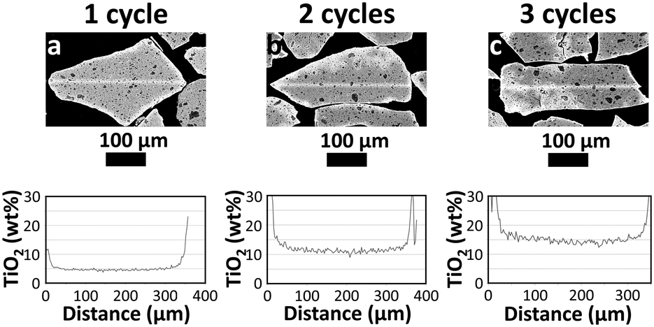 | ||
| Fig. 3 SEM-EDX line scans showing the TiO2 distribution along the cross-section of the TiO2–Al2O3 particles after 1, 2 and 3 TTIP ALD cycles (a, b and c, resp.). The location of the line scan is evident in the images as a brighter line across the length of the selected particle. | ||
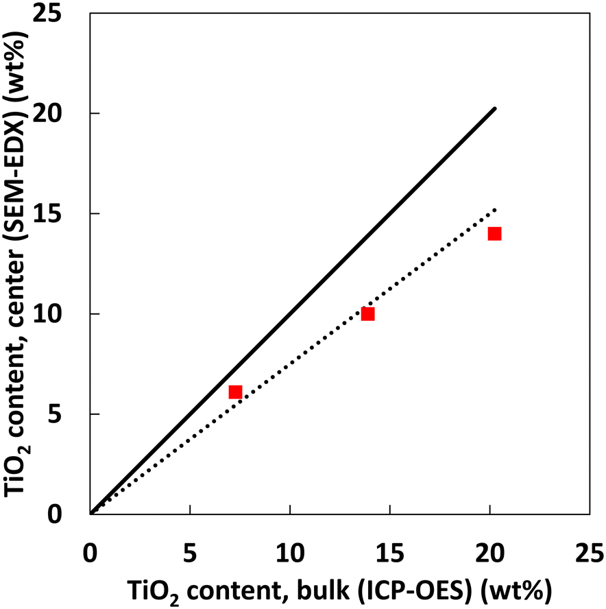 | ||
| Fig. 4 Correlation of the bulk TiO2 content (measured by ICP-OES) and the semi-quantitative TiO2 content near the centre of the particles (determined by SEM-EDX) for samples overcoated with 1, 2 and 3 ALD cycles. The lines are meant to guide the eye and represent 100% parity (solid) and 75% parity (round dot) respectively. | ||
Despite the homogeneous distribution of the deposited species, coating the inner pores could induce a significant decrease in the specific surface area of the alumina support due to pore blockage. To assess this, the pore size distribution was estimated for one of the samples coated with a single ALD cycle (7.3 wt% TiO2), using N2 physisorption (Fig. 5). Similar pore size distributions between the uncoated and coated samples are observed, with a maximum in the pore size distribution curve at the same pore diameter. The delta pore volume (normalized as ml of N2 adsorbed per g of alumina support) is only slightly larger than expected, based on the density of bulk TiO2. It is concluded that the differences between the alumina and the Ti-coated alumina are minor: no extensive pore blocking has taken place.
 | ||
| Fig. 5 Pore size distribution (volumetric, normalized) of the uncoated mesoporous alumina support (blue profile, circles) and a single TTIP ALD cycle overcoated sample (orange profile, squares) that contains 7.3 wt% TiO2. | ||
The effect of TiO2 deposition on the surface area of the Al2O3–TiO2 materials measured by hexane adsorption (Table 1) confirms that when normalized on γ-alumina (Al2O3) basis, no noticeable decrease is observed.
Catalytic activity
The three samples coated by 1, 2 and 3 cycles were used as support for the synthesis of CoMo hydroprocessing catalysts. The HDS catalytic activities of the three coated samples were measured in hydrotreatment of LGO under relevant industrial conditions (350 °C, 45 bar) in a multi-tubular testing unit (for details see ESI†). The HDS activity of the samples is benchmarked against a CoMo/Al2O3 catalyst synthesized directly on the pristine alumina support (Fig. 6). | ||
| Fig. 6 HDS activity (RMA) of TiO2–Al2O3 supported CoMo catalysts. The Al2O3 support was overcoated with 1, 2 and 3 TTIP ALD cycles resulting in 7, 14 and 20 wt% TiO2 respectively. For benchmarking, the activity of the analogous reference catalyst without a TiO2 overcoating is included. | ||
All the catalysts based on the Ti-coated supports showed significantly higher activity than the reference catalyst. Up to 40% higher relative activity in HDS per Mo atom was obtained for the sample that was modified with 2 ALD overcoat cycles. It is clear that the introduction of the highly dispersed TiO2 in the catalysts has a beneficial effect on activity, in line with previous reports. We speculate that the observed optimum in activity is related to the dispersion of the Ti species. As the Ti content increases with the number of ALD cycles, approaching the order of a monolayer coating (18–21.5 wt%), the dispersion of the Ti species might be slightly decreasing for the highest Ti loading. Further evaluation of the porosity characteristics for varied Ti contents, and a careful study on the catalyst acidity characteristics and the dispersion of the active phases are expected to enable a better understanding of the reasons behind the increase of the catalytic activity.
Morphology and dispersion of deposited species after the catalyst testing
Besides the distribution and dispersion of the TiO2, the morphology of the active CoMoS phase was investigated by TEM (details in ESI†). Imaging of the 7.3 wt% TiO2–Al2O3 support and an analogous, spent CoMoS/TiO2–Al2O3 catalyst (Fig. 7) showed, in agreement with the SEM-EDX results, a homogeneous distribution of Ti and Al. At low magnification, the Al and Ti element maps overlap almost perfectly and there are no separate TiO2 particles observed. At higher magnification, nm-scale Ti oxide particles are observed, evenly distributed and dispersed onto a porous matrix. The obtained images suggest that the TiO2 deposition has resulted in the formation of very small particles in the range of ca. 1 nm in size, distributed homogeneously throughout the pores of the Al2O3 without any blockage of the pores. As expected, the Ti and Al distribution for the support and the spent catalyst after the catalytic testing are very similar. This similarity indicates that there are no signs of agglomeration during catalyst preparation (impregnation with an aqueous metal solution followed by drying). It is promising that the exposure of the catalyst at the demanding reaction conditions (350 °C, 45 bar) did not seem to influence the dispersion of the TiO2. Even in samples with a higher Ti loading, the Ti oxide species remained highly dispersed throughout the porous matrix, for both fresh and used samples.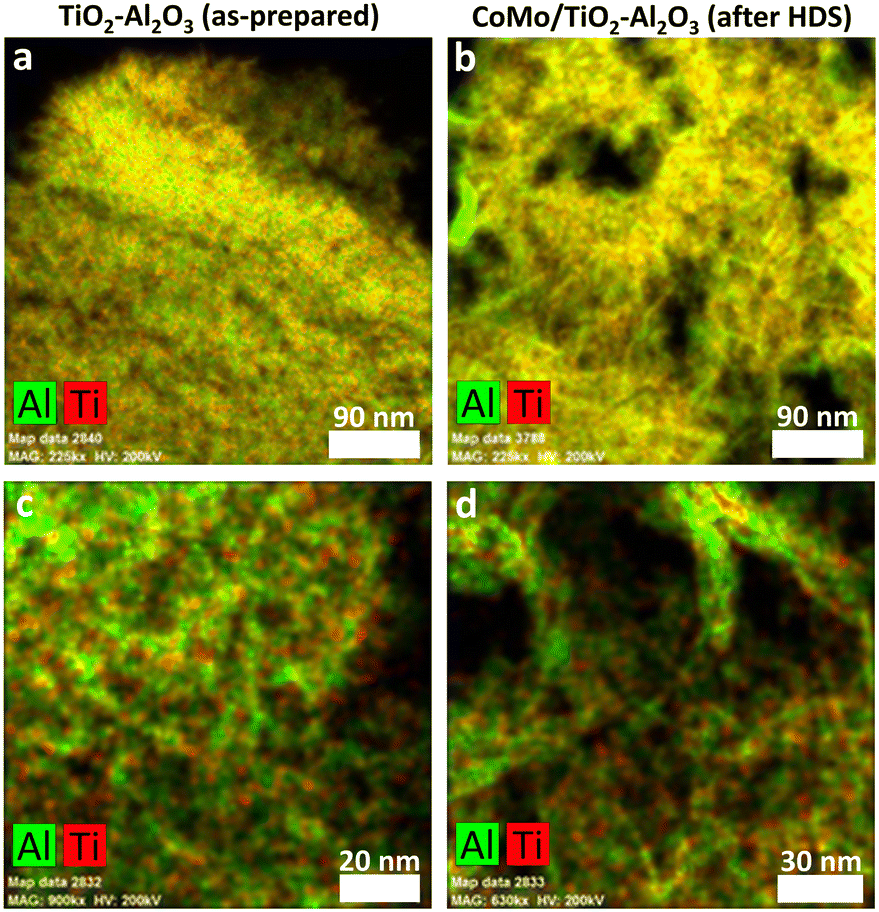 | ||
| Fig. 7 Distribution of Al and Ti in a representative TiO2–Al2O3 catalyst support (7.3 wt% TiO2, a and c) and a spent CoMo catalyst supported on the overcoated TiO2–Al2O3 catalyst support (7 wt% TiO2, b and d) assessed by TEM-EDX. Red: Ti; green Al. | ||
High resolution TEM images of spent catalysts were used to determine the morphology and dispersion of the CoMoS active phase, based on the sample after a single ALD cycle (7 wt% TiO2) as shown in Fig. 8. The CoMoS slabs can be observed as black lines, which are in fact projections of the 2-dimensional MoS2 slabs as observed side-on. Mostly single slabs of 3–7 nm can be observed, but in areas with higher local metal loading, some stacking of the slabs was evident. The slabs positioning seems to follow the contour of the support particles, in agreement with previous visualization via 3-dimensional TEM imaging.38,39 No noticeable formation of separate cobalt-sulfide particles was observed. Altogether it can be concluded that the introduction of TiO2 in the support via ALD has not resulted in any drastic modification of the active phase. Quantification of the dispersion of the active phase is notoriously difficult due to (i) sample inhomogeneity which makes it difficult to obtain a representative set of images for quantification, (ii) the potential presence of small CoMoS slabs that cannot be traced in the current TEM resolutions (and could contribute to a large amount of active sites), (iii) the large error associated to counting and size measurement of active sites, (iv) the large error associated to counting and size measurement of the observed slabs. As the main objective of this study was to determine the applicability of ALD for the deposition of TiO2 overcoats in relevant mesoporous catalyst support materials and its positive effect on catalyst activity, we did not attempt any further quantification.
 | ||
| Fig. 8 High resolution TEM images on several sample locations (a–d) of a spent overcoated CoMoS catalyst (7 wt% TiO2 after 1 TTIP ALD cycle) obtained after the catalytic performance testing. | ||
The results strongly suggest that the deposition of TiO2 did not have a significant effect on the dispersion of the CoMoS phase. We conclude that the positive effect of TiO2 overcoating on the catalytic performance is not the result of an increased dispersion, in agreement with the suggestion of a modification of the support (a lower support active phase interaction) or of a direct function for titanium sites similar to Ni and Co.10,11 A modification of the electronic structure of the active phase could be the origin,5,40 while the TiO2-surface could also play a role in reaction pathways that facilitate the HDS reaction, such as isomerization of substituted dibenzothiophenes.41–43 Determining the exact effect of the TiO2 overcoat on the activity is beyond the scope of this study.
ALD of TiO2 onto porous Al2O3 supports—such as mesoporous powders typically used in catalysis applications—has already been showcased in the 1990s pioneering ALD research collaboration of Microchemistry and Neste.23–28 Further research30,31,44 has proven the benefits of ultrathin coatings in catalytic applications. This is the first report that presents extensive evidence on the intra-particle and inter-particle distribution of the Ti-oxide overcoat. A clear performance benefit, under industrially-relevant conditions, is observed and attributed to the overcoat.
Conclusions
The feasibility of titanium tetra-isopropoxide as ALD precursor for the synthesis of mesoporous TiO2–Al2O3 with high homogeneity on the intra-particle and inter-particle levels was demonstrated. The overcoated TiO2–Al2O3 is an excellent support for the synthesis of a hydroprocessing catalyst with respect to catalytic activity and structural stability of the active phase, although long-term stability remains to be proven. Under reaction conditions, an evenly distributed coating of TiO2 is present. ALD is a simple and scalable method that allows solvent-free synthesis of precisely-defined structured catalyst supports.Author contributions
Jacob A. Moulijn: conceptualization, supervision, writing. J. Ruud van Ommen: conceptualization, methodology. Aristeidis Goulas: conceptualization, formal analysis, investigation, methodology, writing. David Valdesueiro: formal analysis, investigation. Jana Juan-Alcañiz: conceptualization, investigation. Kar-Ming Au-Yeung: investigation. Leo Woning: formal analysis, investigation. Jaap A. Bergwerff: conceptualization, supervision, writing.Conflicts of interest
There are no conflicts to declare.Acknowledgements
The authors would like to acknowledge Jauffrey Lescoffit (Delft IMP) for performing the coating experimental work and Theo de Jong (Ketjen) for conducting the SEM-EDX line scans.Notes and references
- H. Topsøe, B. S. Clausen and F. E. Massoth, in Catalysis-Science and Technology, ed. J. R. Anderson and M. Boudart, Springer, Berlin, Heidelberg, 1996, vol. 11 Search PubMed.
- H. Toulhoat and P. Raybaud, Catalysis by transition metal sulphides : from molecular theory to industrial application, Editions Technip, Paris, France, 2013 Search PubMed.
- S. Eijsbouts, Appl. Catal., A, 1997, 158, 53–92 CrossRef CAS.
- H. Shimada, Catal. Today, 2003, 86, 17–29 CrossRef CAS.
- M. Breysse, P. Afanasiev, C. Geantet and M. Vrinat, Catal. Today, 2003, 86, 5–16 CrossRef CAS.
- G. M. Dhar, B. N. Srinivas, M. S. Rana, M. Kumar and S. K. Maity, Catal. Today, 2003, 86, 45–60 CrossRef CAS.
- W. Zhou, L. Yang, L. Liu, Z. Chen, A. Zhou, Y. Zhang, X. He, F. Shi and Z. Zhao, Appl. Catal., B, 2020, 268, 118428 CrossRef CAS.
- S. K. Maity, J. Ancheyta, M. S. Rana and P. Rayo, Energy Fuels, 2006, 20, 427–431 CrossRef CAS.
- J. Ramirez, L. Ruiz-Ramirez, L. Cedeno, V. Harle, M. Vrinat and M. Breysse, Appl. Catal., A, 1993, 93, 163–180 CrossRef CAS.
- C. Arrouvel, M. Breysse, H. Toulhoat and P. Raybaud, J. Catal., 2005, 232, 161–178 CrossRef CAS.
- L. Coulier, J. A. R. van Veen and J. W. Niemantsverdriet, Catal. Lett., 2002, 79, 149–155 CrossRef CAS.
- E. Y. Kaneko, S. H. Pulcinelli, V. Teixeira da Silva and C. V. Santilli, Appl. Catal., A, 2002, 235, 71–78 CrossRef CAS.
- B. J. O'Neill, D. H. K. Jackson, J. Lee, C. Canlas, P. C. Stair, C. L. Marshall, J. W. Elam, T. F. Kuech, J. A. Dumesic and G. W. Huber, ACS Catal., 2015, 5, 1804–1825 CrossRef.
- C. Detavernier, J. Dendooven, S. Pulinthanathu Sree, K. F. Ludwig and J. A. Martens, Chem. Soc. Rev., 2011, 40, 5242–5253 RSC.
- J. R. van Ommen, A. Goulas and R. L. Puurunen, in Kirk-Othmer Encyclopedia of Chemical Technology, 2022 Search PubMed.
- J. Lu, J. W. Elam and P. C. Stair, Acc. Chem. Res., 2013, 46, 1806–1815 CrossRef CAS PubMed.
- J. R. van Ommen and A. Goulas, Mater. Today Chem., 2019, 14, 100183 CrossRef CAS.
- Y. J. Pagán-Torres, J. Lu, E. Nikolla and A. C. Alba-Rubio, in Studies in Surface Science and Catalysis, ed. P. Fornasiero and M. Cargnello, Elsevier, 2017, vol. 177, pp. 643–676 Search PubMed.
- J. V. Muntean, J. A. Libera, S. W. Snyder, T. Wu and D. C. Cronauer, Energy Fuels, 2013, 27, 133–137 CrossRef CAS.
- W. W. McNeary, S. A. Tacey, G. D. Lahti, D. R. Conklin, K. A. Unocic, E. C. D. Tan, E. C. Wegener, T. E. Erden, S. Moulton, C. Gump, J. Burger, M. B. Griffin, C. A. Farberow, M. J. Watson, L. Tuxworth, K. M. Van Allsburg, A. A. Dameron, K. Buechler and D. R. Vardon, ACS Catal., 2021, 11, 8538–8549 CrossRef CAS.
- S. Said and A. A. Abdelrahman, J. Sol-Gel Sci. Technol., 2020, 95, 308–320 CrossRef CAS.
- A. Goulas and J. R. van Ommen, Kona Powder Part. J., 2014, 31, 234–246 CrossRef.
- E. L. Lakomaa, S. Haukka and T. Suntola, Appl. Surf. Sci., 1992, 60–61, 742–748 CrossRef CAS.
- S. Haukka, E. L. Lakomaa and T. Suntola, Thin Solid Films, 1993, 225, 280–283 CrossRef CAS.
- S. Haukka, E. L. Lakomaa, O. Jylha, J. Vilhunen and S. Hornytzkyj, Langmuir, 1993, 9, 3497–3506 CrossRef CAS.
- E.-L. Lakomaa, Appl. Surf. Sci., 1994, 75, 185–196 CrossRef CAS.
- S. Haukka, A. Kytökivi, E. L. Lakomaa, U. Lehtovirta, M. Lindblad, V. Lujala and T. Suntola, in Studies in Surface Science and Catalysis, ed. G. Poncelet, J. Martens, B. Delmon, P. A. Jacobs and P. Grange, Elsevier, Louvain-La-Neuve, 1995, vol. 91, pp. 957–966 Search PubMed.
- M. Lindblad, S. Haukka, A. Kytökivi, E.-L. Lakomaa, A. Rautiainen and T. Suntola, Appl. Surf. Sci., 1997, 121–122, 286–291 CrossRef.
- J. Keränen, C. Guimon, E. Iiskola, A. Auroux and L. Niinistö, Catal. Today, 2003, 78, 149–157 CrossRef.
- J. Lu, K. M. Kosuda, R. P. Van Duyne and P. C. Stair, J. Phys. Chem. C, 2009, 113, 12412–12418 CrossRef CAS.
- N. Yang and S. F. Bent, J. Catal., 2017, 351, 49–58 CrossRef CAS.
- J.-P. Niemelä, G. Marin and M. Karppinen, Semicond. Sci. Technol., 2017, 32, 093005 CrossRef.
- A. P. Didden, J. Middelkoop, W. F. A. Besling, D. E. Nanu and R. V. D. Krol, Rev. Sci. Instrum., 2014, 85, 013905 CrossRef PubMed.
- J. N. Louwen and R. J. Jonker, Method of analyzing microporous material, US2002/0110921A1, 2002.
- A. M. Johnson and P. C. Stair, J. Phys. Chem. C, 2014, 118, 29361–29369 CrossRef CAS.
- H. Knözinger and P. Ratnasamy, Catal. Rev.: Sci. Eng., 1978, 17, 31–70 CrossRef.
- M. Digne, P. Sautet, P. Raybaud, P. Euzen and H. Toulhoat, J. Catal., 2002, 211, 1–5 CrossRef CAS.
- S. Eijsbouts, X. Li, J. Juan-Alcaniz, L. C. A. van den Oetelaar, J. A. Bergwerff, J. Loos, A. Carlsson and E. T. C. Vogt, ACS Catal., 2017, 7, 4817–4821 CrossRef CAS.
- K. P. de Jong, L. C. A. van den Oetelaar, E. T. C. Vogt, S. Eijsbouts, A. J. Koster, H. Friedrich and P. E. de Jongh, J. Phys. Chem. B, 2006, 110, 10209–10212 CrossRef CAS PubMed.
- R. Burch and A. Collins, J. Catal., 1986, 97, 385–389 CrossRef CAS.
- S. A. Giraldo and A. Centeno, Catal. Today, 2008, 133–135, 255–260 CrossRef CAS.
- T. Isoda, S. Nagao, X. Ma, Y. Korai and I. Mochida, Energy Fuels, 1996, 10, 1078–1082 CrossRef CAS.
- M. V. Landau, D. Berger and M. Herskowitz, J. Catal., 1996, 159, 236–245 CrossRef CAS.
- R. Lobo, C. L. Marshall, P. J. Dietrich, F. H. Ribeiro, C. Akatay, E. A. Stach, A. Mane, Y. Lei, J. Elam and J. T. Miller, ACS Catal., 2012, 2, 2316–2326 CrossRef CAS.
Footnote |
| † Electronic supplementary information (ESI) available. See DOI: https://doi.org/10.1039/d3cy00335c |
| This journal is © The Royal Society of Chemistry 2023 |