 Open Access Article
Creative Commons Attribution 3.0 Unported Licence
Advanced crystallisation methods for small organic molecules
J. P.
Metherall
 *a,
R. C.
Carroll
 b,
S. J.
Coles
 b,
M. J.
Hall
 *a and
M. R.
Probert
 *a
*a
aNewcastle University, Chemistry – School of Natural Environmental Sciences, Newcastle upon Tyne, NE1 7RU, UK. E-mail: j.metherall@newcastle.ac.uk; michael.hall@newcastle.ac.uk; michael.probert@newcastle.ac.uk
bUniversity of Southampton, School of Chemistry, Southampton, SO17 1BJ, UK
First published on 1st March 2023
Abstract
Molecular materials based on small organic molecules often require advanced structural analysis, beyond the capability of spectroscopic techniques, to fully characterise them. In such cases, diffraction methods such as single crystal X-ray diffraction (SCXRD), are one of the most powerful tools available to researchers, providing molecular and structural elucidation at atomic level resolution, including absolute stereochemistry. However SCXRD, and related diffraction methods, are heavily dependent on the availability of suitable, high-quality crystals, thus crystallisation often becomes the major bottleneck in preparing samples. Following a summary of classical methods for the crystallisation of small organic molecules, this review will focus on a number of recently developed advanced methods for crystalline material sample preparation for SCXRD. This review will cover two main areas of modern small organic molecule crystallisation, namely the inclusion of molecules within host complexes (e.g., “crystalline sponge” and tetraaryladamantane based inclusion chaperones) and the use of high-throughput crystallisation, employing “under-oil” approaches (e.g., microbatch under-oil and ENaCt). Representative examples have been included for each technique, together with a discussion of their relative advantages and limitations to aid the reader in selecting the most appropriate technique to overcome a specific analytical challenge.
Key learning points1. To appreciate the importance of single crystal X-ray diffraction for the structural determination of small organic molecules.2. To comprehend the fundamentals of molecular crystallisation and the use of classical crystallisation approaches. 3. To understand the key principles of four modern crystallisation methods: “the crystalline sponge method”, “tetraaryladamantane based inclusion chaperones”, “microbatch under-oil crystallisation” and “encapsulated nanodroplet crystallisation (ENaCt)”. 4. To appreciate the advantages and challenges encountered for different modern crystallisation methods and to understand which is best suited for the analysis of a particular molecule. |
Introduction
Single crystal X-ray diffraction (SCXRD) analysis is a readily-available method that can provide access to both the molecular and extended structure of a crystalline material, at the atomic level.1 Whilst modern nuclear magnetic resonance (NMR) and mass spectrometry (MS) are very important in the characterisation of small organic molecules, they provide only indirect structural information making the determination of complex molecular structure challenging.2 In comparison, diffraction methods such as SCXRD give access to information that can be interpreted to provide direct structural information for a molecule. These interpreted experimental results provide unambiguous structural determination and, if performed to sufficient precision and accuracy even absolute stereochemical assignment.3–6 However, SCXRD has an inherent limitation in that it requires the material being analysed to be available in a crystalline state. In particular, for full structural characterisation by SCXRD, the samples must first be prepared as highly ordered single crystals of a particular size (at least 10 μm in each dimension), before any measurement can be performed. Particularly in the field of chemistry, crystallisation experiments have largely revolved around time-consuming manual techniques taking many weeks to complete, typically involving slow evaporation, liquid and vapour diffusion methods, requiring many mg of analyte per experiment.7–9 Thus, a key experimental bottleneck in molecular and structural analysis by SCXRD is the growth or preparation of high-quality single crystals, containing the target compound.Following an overview of crystallisation theory and classical crystallisation techniques, this review will focus on the discussion of modern crystallisation methods. We centre this around small organic molecules aiming to help overcome the crystallisation bottleneck in molecular and structural analysis by SCXRD. Further discussion of alternative crystallisation methods including melt crystallisation,10–13 sublimation,14–16 crystallisation in gels,9,17,18 floating drop,19,20 crystallisation under extreme conditions; high-pressure21,22 and low temperature in situ crystallisation21 can be found in alternative review articles.
1. Crystallisation of small organic molecules from solution
In this section we give an overview of the theory of crystallisation of a small molecule from the solution phase as background for later discussions.23,24 A solubility crystallisation diagram can aid with understanding the crystallisation process, particularly in the case of crystallisation by temperature variation or by evaporation (Fig. 1).23–27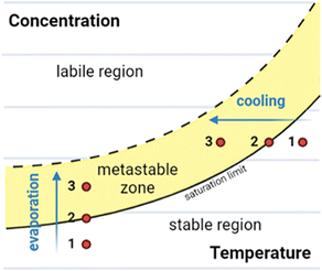 | ||
| Fig. 1 Solubility crystallisation diagram for a molecule in solution, showing the three key regions: stable, metastable, and labile. Crystallisation pathways by evaporation or cooling are indicated. | ||
Solubility crystallisation diagrams can be divided into three main regions in which the molecule is stable, metastable or labile in solution. In the stable region, the concentration of the dissolved molecule is below that of the solubility limit, hence no crystallisation can occur. As the temperature is reduced (cooling) or the loss of solvent occurs (evaporation), the solution will move to the saturation limit, the maximum thermodynamically stable concentration. Further cooling or concentration results in a metastable state (metastable zone) in which the solution is supersaturated but kinetically stable. The third region of the solubility crystallisation diagram is the labile region, an area of supersaturation where spontaneous precipitation (or other phase changes such as “oiling out”) occurs.23,24,28
Using this method, crystals of a molecule are typically grown from an initially subsaturated solution (Fig. 1, point 1). Cooling or evaporation can be used to move to the saturation limit (Fig. 1, point 2) and beyond, into the metastable zone (Fig. 1, point 3). At this stage, following either spontaneous nucleation or the addition of nucleation sites (e.g., seed crystals), crystal growth can begin. Once this has commenced further cooling or evaporation results in further crystal growth, with the crystalline material and molecules in solution in an equilibrium at the saturation limit.26–29
The theory behind nucleation and initial steps in crystal growth remain a complex and active area of research that goes beyond the scope of this review.
2. Classical crystallisation of small molecules from solution for SCXRD
In this section we provide an overview of classical crystallisation techniques suitable for the preparation of crystals of small organic molecules for SCXRD. Traditional crystallisation methodologies employed to produce samples for SCXRD largely revolve around slow growth of crystals from solution.26,27 An overview of the commonly used classical solution phase crystallisation techniques was published by Kroon and co-workers8 and as such, only brief summaries have been included here. Classical solution phase crystallisation techniques for SCXRD include:(i) Evaporation
The molecule of interest is fully dissolved in either a single solvent or mixture of solvents, typically close to the solubility limit, often in a small glass vial. The vial is left open to an atmosphere (e.g., air or N2) under conditions in which the rate of evaporation is slow. Evaporation can take place over a typical period of hours to weeks depending on the solvent. The loss of solvent leads to an increase in the concentration of the solution, until supersaturation is achieved. Following nucleation, continued slow evaporation can result in growth of high-quality crystals (Fig. 2(i)).9,24(ii) Thermal control
In a small glass vial a single solvent or mixture of solvents is added to the molecule of interest to form a saturated solution, in which solid is still present. The vial is then sealed and carefully heated until the molecule is fully dissolved, at which point the solution is cooled slowly in a carefully controlled manner. Following nucleation, continued slow cooling is required for high-quality crystal growth (Fig. 2(ii)).9,24,30(iii) Liquid–liquid diffusion
A solution of the molecule of interest close to the solubility limit, is prepared in a suitable solvent(s), often in a small glass vial. To which is added an appropriate anti-solvent (or precipitant), typically carefully down the side of the vial, to form a discrete layer on top of the solution. The anti-solvent should ideally be less dense to aid the layering process and should also be miscible with the solvent. The vial is then sealed, and over time the anti-solvent slow diffuses into the solution. The slow mixing of the anti-solvent with the solvent, creates an environment in which the molecule is increasingly less soluble until it reaches the saturation limit. Following nucleation, continued slow diffusion results in crystal growth (Fig. 2(iii)). Variants on this technique include the use of ‘H’ tubes where the solution containing the molecule of interest and the anti-solvent are contained in two separate zones of the apparatus, separated by a central diffusion zone in which slow diffusion of the solvent and anti-solvent occurs.9,24(iv) Vapour diffusion
The principle of vapour diffusion is very similar as for liquid–liquid diffusion, whereby an environment is created in which the solubility of the molecule is reduced through the slow addition of an anti-solvent. However, in vapour diffusion the anti-solvent diffuses into the solution via the vapour phase.7,8 To carry out a vapour diffusion experiment, a vial containing the molecule dissolved in suitable solvent near the solubility limit is placed within a larger vessel containing a volatile anti-solvent and the system is sealed. Slow mixing of the anti-solvent into the solvent occurs via the vapour phase until the solubility of the molecule drops sufficiently for crystallisation to occur (Fig. 2(iv)).9,24,31High-throughput automated crystallisation screening systems have been developed in recent years, particularly within the pharmaceutical industry, however these systems are not typically focussed on accessing the high-quality single crystals needed for SCXRD.32–36 Thus the use of classical crystallisation techniques, to access crystals for SCXRD, are still common in research laboratories in both academic and industrial settings. Such classical crystallisation techniques do however suffer from a number of inherent limitations, namely the large amount of material consumed during sample preparation and the time taken to set-up the vast number of experiments typically required to access a crystal form. In addition, classical crystallisation techniques cannot give information on samples that are liquids at room temperature. In order to overcome some of the limitations of classical techniques, recently four methods have emerged which allow small molecules to be investigated by SCXRD.
3. The crystalline sponge method
The “crystalline sponge” method as defined by Fujita and co-workers, allows for the structural analysis of small molecules by SCXRD, without the need to crystallise the molecule of interest, and can even be used for samples that are liquids under ambient conditions.37 A crystalline sponge is a single crystal of a metal organic framework (MOF) containing pores which can encapsulate small molecules and promote their long-range ordering within the framework.38 Once prepared, such MOFs containing ordered guest molecules can be analysed by SCXRD and the molecular structure of the guest determined (Fig. 3).39MOFs were first described by Hoskins and Robson40,41 as porous molecular frameworks in which metal ions or metal clusters are coordinated to organic ligands to form three-dimensional structures.42–45 When synthesised, the pores of a MOF are typically filled with disordered solvent molecules, however it has been shown that certain MOFs can remain stable following the removal of solvent and the resulting voids can be used to incorporate other molecules, leading to applications in the storage of gases such as hydrogen46 and carbon dioxide.47 Their ability to allow molecules to transfer in and out of their pores have allowed MOFs to be used in electrocatalysis,48 drug-delivery,49,50 water treatment,51,52 bioimaging,53 and even in nuclear waste treatment.54
In 2006, Kim and co-workers published an early example of a small molecule, ferrocene, incorporated into a MOF crystal with sufficient occupancy and long-range order to allow the structure of the guest to be determined by SCXRD.55 In 2010, Fujita and co-workers showed that reactions between two small molecules can occur within a MOF, and that the reaction products could even be characterised by SCXRD studies within the MOF,38 terming these systems “crystalline molecular flasks”.56–58
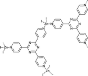
Following this work, Fujita and co-workers39 continued the development of MOF systems that displayed long-range ordering of a variety of different guest molecules allowing for analysis by SCXRD, labelling these MOF systems “crystalline sponges”. The most successful crystalline sponges are based on the [(ZnI2)3(tris(4-pyridyl)-1,3,5-triazine)2] system (Fig. 4). This system involves zinc (II) ions coordinated to tri-valent tris(4-pyridyl)-1,3,5-triazine (tpt) ligands, creating a porous lattice-like structure with infinite channels ∼8 × 5 Å.59 The ligand system employed is composed of electron deficient heteroaromatic rings which allow for strong π–π (face-to-face) or CH–π (edge-to-face) interactions with guest molecules. This encourages long-range ordering of the guests within the pores, making more complete crystallographic analysis possible.57
3.1. Preparation of single crystal crystalline sponges: synthesis and solvent exchange
The preparation of crystalline sponges suitable for guest analysis, involves both the synthesis of the crystalline sponge host as a single crystal of suitable size and solvent exchange ready for guest incorporation. In order to generate high-quality single crystals of the crystalline sponge, suitable for later SCXRD, the synthesis step requires the use of a templating solvent (often nitrobenzene is selected as it can form strong π–π interactions with the tpt ligand).60 To encourage single crystal formation, the synthesis of the crystal sponge is typically carried out slowly over 7 days, utilising the slow evaporation method as described in section 2.39 However, the strongly bound templating solvent molecules can prevent the incorporation of any guest analyte, through competitive binding with the crystalline sponge. Therefore, a solvent exchange step is typically required in which the templating solvent is exchanged for a weakly binding solvent (often cyclohexane), by exposing the crystalline sponge to an excess of the exchange solvent at 50 °C for 7 days. Single crystals, ideally rod-shaped with a length of 30–300 μm, are then selected for later experiments (Fig. 5).59,61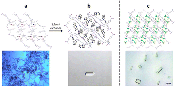 | ||
| Fig. 5 (a) Crystalline sponge with nitrobenzene filling the pores (packing view in the crystallographic [100] direction with hydrogen atoms removed for clarity, CCDC code: 187830). Figure reprinted with permission from ref. 62. Copyright 2016 American Chemical Society. (b) Crystalline sponge with cyclohexane filling the pores (packing views in the crystallographic [010] direction, with hydrogen atoms removed for clarity, CCDC code: 1418972). Figure adapted from ref. 37 with permission from John Wiley and Sons, copyright 2021. (c) Single crystal crystalline sponges ready for guest inclusion, with chloroform filling the pores (packing views in the crystallographic [010] direction, with hydrogen atoms removed for clarity, CCDC code: 1007932). Figure reproduced from ref. 63 with permission from American Chemical Society, copyright 2015. | ||
Following the initial publication of the crystalline sponge method, considerable work has been carried out to optimise the preparation of the crystalline sponge crystals.62,64–68 Most notably, Clardy and co-workers were able to reduce synthesis time for single crystal crystalline sponges (suitable for guest analysis) from a total of 14 days to 3 days through use of the more volatile solvent chloroform, instead of nitrobenzene, in the crystal growth step. By using chloroform, the crystals formed did not require the solvent exchange step and were instead ready for immediate use in guest soaking.63,69,70
3.2. Preparation of single crystal crystalline sponges: soaking of guest analyte and analysis of host-guest systems by SCXRD
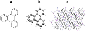
After the preparation and selection of suitable crystalline sponge crystals, soaking of the crystalline sponge, in analyte (either as a neat liquid or in a solution) is then undertaken. The time required for successful soaking varies, depending on the guest analyte employed, most often 2 days, but up to 90 days has been reported.71 The resulting supramolecular complex can then be analysed by SCXRD. The quality of the results obtained is heavily dependent on the level of ordering and occupancy within the pores (Fig. 6).39One of the first successful implementations of a crystalline sponge system for the analysis of a guest molecule was published by Fujita and co-workers in 2004, using triphenylene as the guest (prior the advent of “crystalline sponge” terminology).60 In the procedure, single crystals of crystalline sponge containing nitrobenzene were soaked in a saturated cyclohexane solution of triphenylene at room temperature for 24 hours. Subsequent analysis by SCXRD confirmed the successful incorporation and ordering of triphenylene into the pores of the crystalline sponge. Both triphenylene and the cyclohexane solvent could be observed within the pores in a 1.5 to 2.5 ratio respectively and displayed a level of disorder within the structure (Fig. 7).
The incorporation of solvent molecules alongside guests within a crystal sponge, especially if disordered, tends to complicate any structure refinement. Improvements in solvent exchange and soaking processes, as discussed previously, have subsequently helped to alleviate this problem.63,69
Following the successful work with triphenylene, the crystalline sponge method has been applied to the structural determination by SCXRD of over 60 host–guest systems to date.39,67,72–83 Additionally, crystalline sponges have been used in combination with chromatographic separation techniques (HPLC39 and GC84), characterisation of drug metabolites,85 and organometallic compounds.86
3.3. Crystalline sponges for absolute stereochemistry of guest molecules
Despite the large number of published crystalline sponge host–guest systems, the resolution of absolute stereochemistry for a guest molecule is complex with only a small number of examples known. The determination of absolute stereochemistry requires the analysis of the anomalous scattering in the X-ray diffraction pattern, often reported via the Flack parameter.4,5 The presence of heavy atoms, such as halides in the crystalline sponge host, can assist in the absolute stereochemical determination of light-atom chiral guests.An early example of guest absolute stereochemistry determination was attempted by Fujita and co-workers, in the analysis of the sample limited marine natural product miyakosyne A.39,87,88 Miyakosyne A is a long chain lipophilic acetylene isolated from marine sponge Petrosia sp., containing 3 chiral centres (Fig. 8). Following the incorporation of miyakosyne A (5 μg) into the crystalline sponge [(ZnI2)3(tpt)2(C6H12)x]n, SCXRD analysis was undertaken. Due to low guest occupancy (∼50%) and the presence of disordered cyclohexane solvent, an attempt to improve structural refinement using SQUEEZE89 was applied. However considerable disorder of the guest was observed, meaning that stereochemical resolution at the C3, C14 and C26 positions remained ambiguous.90
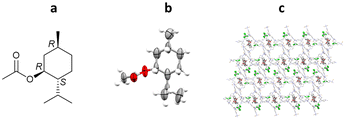
More recent work by Clardy and co-workers has demonstrated the determination of absolute stereochemistry of (1R)-menthyl acetate.63,69 As (1R)-menthyl acetate is a liquid under ambient conditions, the use of crystalline sponge method was chosen to allow for absolute stereochemistry determination by anomalous dispersion. Clardy and co-workers further modified the crystalline sponge methodology (Section 3.1) by replacing the metal salt used in the synthesis (ZnI2) with either ZnCl2 or ZnBr2. The replacement of the iodide in the host structure with chloride or bromide was undertaken in an attempt to increase the relative contribution of the guest to the X-ray diffraction pattern.
In this experiment, crystalline sponge crystals were grown from ZnCl2, ZnBr2 and ZnI2 in CHCl3/MeOH with tpt. Direct incorporation of (1R)-menthyl acetate, as a neat liquid, was then performed into all three crystal sponge variants. The resulting host–guest complexes were analysed by SCXRD showing the incorporation of (1R)-menthyl acetate along with residual CHCl3. In this case, the high-level ordering of both guest and solvent molecules removed the need to utilise SQUEEZE, in line with recent guidelines which recommend avoiding the use of masking routines when analysing guests within a crystalline sponge system.89,91 Comparison of the three systems showed some key differences. Notably, the unit cell volume increases drastically for the iodide variant (33![[thin space (1/6-em)]](https://www.rsc.org/images/entities/char_2009.gif) 764 Å3, compared to 14
764 Å3, compared to 14![[thin space (1/6-em)]](https://www.rsc.org/images/entities/char_2009.gif) 211 Å3 and 14
211 Å3 and 14![[thin space (1/6-em)]](https://www.rsc.org/images/entities/char_2009.gif) 742 Å3 for the chloride and bromide variants respectively). Most importantly, the occupancy levels of the guest molecules change across the series: 95% chloride, 86% bromide and 73% iodide. The high % occupancy for the chloride and bromide systems aided the guest modelling during refinement, with minimal soft restraints applied (80 and 95 for chloride and bromide systems respectively, versus 1137 for the iodide system), and the absolute stereochemistry confirmed by the Flack parameter (Flack = 0.054(19), 0.05(2) and 0.02(2) respectively) (Fig. 9).69
742 Å3 for the chloride and bromide variants respectively). Most importantly, the occupancy levels of the guest molecules change across the series: 95% chloride, 86% bromide and 73% iodide. The high % occupancy for the chloride and bromide systems aided the guest modelling during refinement, with minimal soft restraints applied (80 and 95 for chloride and bromide systems respectively, versus 1137 for the iodide system), and the absolute stereochemistry confirmed by the Flack parameter (Flack = 0.054(19), 0.05(2) and 0.02(2) respectively) (Fig. 9).69
3.4. Crystalline sponges for the determination of natural products: terpenes from hops
Structural determination of sample limited complex natural products is very challenging, making SCXRD the method of choice for analysis, especially when absolute stereochemical determination is required. However, many natural products are liquids under ambient conditions or do not crystallise readily, in which cases the use of the crystalline sponge method is favoured. In recent work by Taniguchi, Fujita and co-workers, crystalline sponges were used to elucidate the structures of several complex breakdown products of trans-isohumulone, a terpeniod isolated from hops (Humulus lupulus). A ZnCl2 based crystalline sponge was selected for this work, in which the synthesis solvent had been exchanged for n-hexane [(ZnCl2)3(tpt)2(n-hexane)x]n. Following separation of the trans-isohumulone breakdown products by HPLC, 13 isolated molecules were loaded into the crystalline sponges from a dimethyl ether solution, and analysed by SCXRD. The structures and absolute stereochemistries of all 13 trans-iso-α-acids were solved (with minimal restraints required), 8 of which were previously unknown molecules, including dicyclohumol A (Flack = 0.054(8)) (Fig. 10).923.5. Advantages and challenges associated with the crystalline sponge method
There are two major advantages of using the crystalline sponge method over classical crystallisation. Firstly, the crystalline sponge method does not require crystallisation of the analyte itself and can therefore be used for the structural analysis by SCXRD of both liquids and non-crystalline solids. Secondly, the crystalline sponge method has been shown to work with highly sample limited analytes for which only micrograms are available, such as metabolites or natural products.However, crystalline sponge methods also have some inherent limitations. Physical separation of the guest molecules means that the technique cannot give information about solid-state packing of the analyte on its own, but rather gives information on interactions of the guest with the host. Furthermore, there is a maximum analyte size that can be accommodated within the pores of the currently utilised crystalline sponges, with the largest guest reported to date having a molecular weight of 428 Da.39
Other challenges in the application of crystalline sponge methods include the need for careful preparation of the suitable crystalline sponge single crystals for guest soaking, with improved methods available.59,69 It is also important to select a suitable crystalline sponge host for the guest analyte, which maximises occupancy and ordering of the guest within the pores.93
Over the course of only 10 years, the crystalline sponge method has become highly impactful, being successfully applied to the structural solution of a wide range of small organic molecules.37 Since their inception, other related MOF systems have also been evaluated for the structural analysis of guest molecules, for example Yaghi's chiral MOF-520 which employs directional H-bonding to study a series of encapsulated organic acids with simultaneous assignment of the absolute stereochemistry of the guest.94
4. Tetraaryladamantane based inclusion chaperones
An alternative host-aided crystallisation approach which allows for structural analysis of small organic molecules by SCXRD, including liquids, is the use of tetraaryladamantane (TAA) inclusion chaperones. The TAA chaperones are a family of organic molecules with tetrahedral-like symmetry, consisting of four aromatic groups attached to the bridgehead positions of an adamantane core. TAAs are capable of co-crystallising with a wide range of guest analytes, in-part due to the four aromatic groups allowing for π–π (face-to-face) or CH–π (edge-to-face) interactions between the TAA molecules and guest. Once co-crystallised with the guest analyte, suitable crystals can be analysed by SCXRD, and the molecular structure of the guest analyte can be determined (Fig. 11). | ||
| Fig. 11 TAA inclusion chaperone crystallisation. (a) Co-crystallisation of guest and TAA chaperone, and (b) analysis of a suitable crystal by SCXRD. | ||
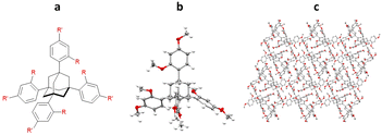
Initial work by Richert and co-workers involved the synthesis and study of four related tetraaryladamantanes: 1,3,5,7-tetrakis(2,4-dimethoxyphenyl)adamantane (TDA), 1,3,5,7-tetrakis(4-methoxyphenyl)adamantane, 1,3,5,7-tetrakis(4-methoxy-2-methylphenyl)adamantane and 1,3,5,7-tetrakis(4-methoxy-2-ethylphenyladamantane). They observed that of these compounds, TDA had a tendency to form analyte inclusion complexes with 20 different solvents, whilst the other TAAs studied did not. This promiscuity towards co-crystallisation with small molecule guest analytes, led Richert and co-workers to further develop this class of molecules as inclusion chaperones (Fig. 12).95
One of the first examples of the use of TAAs as inclusion chaperones for the structural elucidation of a small molecule by SCXRD, involved the co-crystallisation of benzoyl chloride with TDA. TDA was dissolved in hot benzoyl chloride, with co-crystallisation occurring upon slow cooling. The resulting TDA-benzoyl chloride co-crystals were washed with cyclohexane, to remove excess benzoyl chloride, and analysed by SCXRD. The resulting structure contains two TDA molecules and one benzoyl chloride molecule in the asymmetric unit. Interestingly the structure shows π–π interactions between the benzoyl chloride and the aromatic ring of the TDA framework (centroid-to-centroid ≈ 4.0 Å) (Fig. 13).96
Following successful co-crystallisations with TDA, further development resulted in a new inclusion chaperone, 1,3,5,7-tetrakis(2,4-diethoxyphenyl)adamantane (TEO), which was shown to form 7 solvates with molecules including benzene, dioxane and pyrrolidine.97 The use of both TEO and TDA inclusion chaperones has resulted in the discovery of 23 TAA-analyte co-crystals, with different small molecules, over the course of three years. Examples have included analytes as diverse as [12]-crown-4, morpholine and even reactive compounds such as cyclohexyl isocyanide.95–99
4.1. Absolute stereochemistry determination of (R)-methylbenzylamine using a TEO Inclusion chaperone
More recently, Richert and co-workers have applied TAA inclusion chaperones to absolute stereochemistry determination, as exemplified by (R)-methylbenzylamine. In this study, TEO (2 mg) was dissolved in hot (150 °C) (R)-methylbenzylamine (29 μL), cooled to room temperature and left overnight to crystallise. TEO-(R)-methylbenzylamine co-crystals were obtained, analysed by SCXRD, and the absolute configuration confirmed as (R)- with a statistically significant Flack parameter of 0.02(13) (Fig. 14).100This method was applied to a total of 21 enantiopure chiral small molecules, 16 of which formed TEO-analyte co-crystals suitable for which absolute stereochemical assignment could be confirmed.100
4.2. Structural determination of a lipophilic guest using TBro inclusion chaperones: n-decane
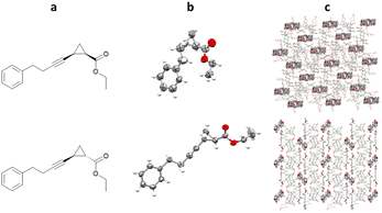
Richert and co-workers have also developed the halogenated chaperone 1,3,5,7-tetrakis(2-bromo-4-phenyl)adamantane (TBro), for the study of lipophilic analytes.100 Screening of TDA, TEO and TBro for co-crystallisations with lipophilic molecules, showed that TBro was the chaperone of choice for this particular molecular class. For example unlike TDA and TEO, TBro was successfully co-crystallised with n-decane and subsequentially analysed by SCXRD (Fig. 15).TBro can also be used for more complex lipophilic analytes, such as ethyl 2-(4-phenylbut-1-yn-1-yl)cyclopropane-1-carboxylate. Racemic mixtures of cis- and trans- were both co-crystallised with TBro, allowing structural and relative stereochemical assignment for both molecules (Fig. 16).101
4.3. Structural determination of an organic solid using TDA and TEO inclusion chaperones: phenol
All of the example TAA inclusion chaperones discussed so far have been restricted to the analysis of analytes which are liquids under ambient conditions. One example is known in which TAAs have been co-crystallised with a solid analyte, phenol. TEO-phenol co-crystals suitable for SCXRD were successfully grown by slow evaporation of a solution of TEO and phenol in dichloromethane, whilst TDA-phenol co-crystals were grown by liquid–liquid diffusion from a solution of TDA and phenol in dichloromethane, using n-decane as an anti-solvent (Fig. 17).1024.4. Advantages and challenges associated with TAAs inclusion chaperones
It should be noted that, analogous to the crystalline sponge method (Section 3), an inherent limitation of using the TAA based inclusion chaperones is the resulting physical separation of the guest molecules, meaning that this technique cannot give information about solid-state packing of the analyte on its own.However, the TAA inclusion chaperone methodology provides a number of advantages in comparison to classical crystallisations, such as the analysis of liquid analytes by SCXRD, with methods also available for the analysis of solid samples. The analyte scope for the use of TAA based inclusion chaperones can also be tailored through matching of an appropriate TAA to the guest to encourage co-crystal formation, with analytes of molecular weights from 60 to 242 Da having been reported. To date > 70 TAA-analyte co-crystals have been obtained, with a focus on liquid analytes. Since the method has recently been demonstrated with a solid analyte, phenol, this is likely an area for future development.
5. Microbatch under-oil crystallisation
The microbatch under-oil crystallisation technique allows for the crystallisation of water-soluble organic salts, from an aqueous solution under-oil. Overtime slow concentration of the salt solution takes place, controlled by the oil layer, resulting in a supersaturated solution. Nucleation and slow crystal growth can then occur, followed by the analysis of any suitable crystals obtained by SCXRD. Microbatch under-oil crystallisation is typically carried out using multi-well plates allowing for parallel screening of crystal conditions, such as different counterions, with each well containing a few microliters of analyte solution (Fig. 18).103The discovery of crystalline forms of organic salts is of interest in the pharmaceutical sector, particularly in the formulation of active pharmaceutical ingredients (APIs). The discovery of a crystalline organic salt requires exposure of the organic cation (or anion) of interest, in combination with its native counterion, to a wide range of alternative counterions. In each case the least soluble analyte counterion combination would be expected to crystallise from solution. Thus, successful screening methods must allow a wide range of counterions to be investigated and consequently considerable effort has been applied in the development of high-throughput methods for pharmaceutical salt crystallisation.104 Early work by Spingler and co-workers has examined the crystallisation of organic cation salts105 through the use of nano-scale vapour diffusion methods designed and widely utilised in protein crystallisation. Spingler's nano-crystallisation methodology was created to allow high-throughput parallel screening of conditions for organic salt crystal formation with minimal sample usage (requiring ∼100 nL of analyte solution in each experiment), yet still providing crystals suitable for SCXRD analysis.
Spingler and co-workers have subsequently further investigated the crystallisation of organic cation salts, through development of the microbatch under-oil technique,103 also based on a widely utilised technique for the crystallisation of proteins. In the microbatch under-oil technique, salt screening in aqueous solution is combined with an oil layer, which floats on the aqueous layer, slowing down any evaporative loss and sample concentration, with the aim of obtaining high-quality single crystals for analysis by SCXRD.
5.1. Microbatch under-oil crystallisation for APIs
Microbatch under-oil crystallisation was tested on five organic salts, all of which were small molecule APIs used in the treatment of: diabetes ((rac)-carnitinenitrile and (R)-carnitinenitrile chloride), asthma ((1S,2R)-ephedrine hydrochloride), hypertension ((8S,14S)-ditiazem hydrochloride), and clinical depression (trazodone hydrochloride) (Fig. 19).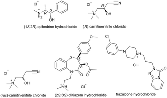 | ||
| Fig. 19 Organic cations (chlorides and hydrochlorides) subjected to microbatch under-oil screening for new salt discovery. | ||
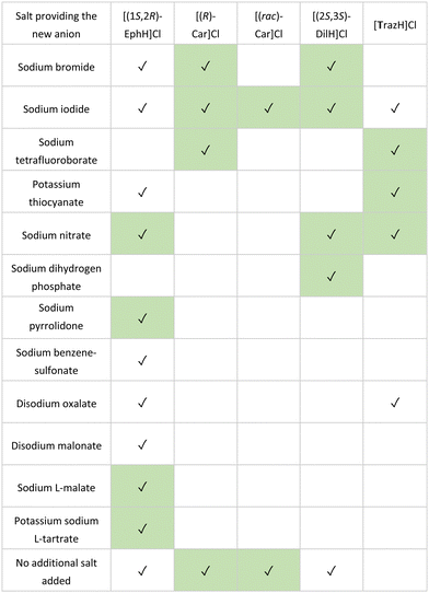
In the study, 86 counterions were selected for screening, chosen for their known propensity to form crystalline salts in combination with their low toxicity (Generally Recognized As Safe, GRAS)106,107 In each case, silicone oil (100 μL) was first added to each well of a 96-well plate (costar, Corning). This was followed by the addition of stock solutions (4–5 μL, 90% saturation in water) of the organic cation to be assessed, and a stock solution of the counterion (5–10 μL) to form a single aqueous droplet under the oil. After 30 days, each crystallisation experiment was examined for successful crystallisations. In all five cases, crystals suitable for SCXRD analysis were obtained, affording a total 27 salts structures, including 17 previously unknown salts (Table 1).
5.2. Advantages and challenges associated with microbatch under-oil crystallisation
A major advantage of using microbatch under-oil for the crystallisation of organic salts, is that a wide range of crystallisation conditions can be screened in parallel with low sample requirements. Typically, to examine 96 crystallisation conditions only a few hundred milligrams of analyte are needed. Since microbatch under-oil gives access to crystals which only contain the molecule of interest and its counterion, information about both the molecular structure and solid-state packing can be obtained via SCXRD analysis, such information is crucial for API development. The largest organic salt examined by microbatch under-oil has a molecular weight of 542 Da, however this technique has the potential for use with much larger molecules.The major current limitation of the microbatch under-oil technique is that the analytes of interest must be water soluble. However, due to the propensity of polar organic molecules in medicinal chemistry, this method would still be applicable around 50% of known solid APIs.107
6. Encapsulated nanodroplet crystallisation
Encapsulated Nanodroplet Crystallisation (ENaCt) is a high-throughput automated method which allows for the crystallisation of organic soluble small molecules on a nanolitre scale. ENaCt involves the injection of a few micrograms of analyte, dissolved in an organic solvent (∼50 nL), into a droplet of inert oil (∼200 nL).108 This encapsulation of the analyte solution within the oil droplet results in a slow loss of solvent over time, leading to a gradual increase in concentration, resulting in the nucleation and growth of crystals for SCXRD analysis. ENaCt is related to “microbatch under-oil” techniques, but allows the use of organic solvents, greatly expanding the analyte scope. In addition, the use of automated experimental set-up allows for parallel high-throughput screening of many experimental crystallisation conditions with minimal sample requirements (Fig. 20).A typical ENaCt experiment involves the use of a liquid handling robot to dispense droplets of oil (∼200 nL) into each well of the 96-well glass plate (Laminex or SWISSSCI LCP, 100 μm spacer), with a range of hydrocarbon, fluorinated and silicon-based oils employed (mineral oil (MO), Fomblin YR (FY), Fluorinert (FC40), and polydimethyl siloxane (PDMSO)). A near saturated solution of analyte (∼50 nL), in organic solvent(s), is then injected into the pre-prepared oil droplets and secondary solvents added if required. Oil encapsulation helps to regulate the rate of sample concentration, by reducing the surface area of the organic solvent droplet from which evaporation can occur. The plates are then sealed with a glass cover slip and stored for up to 14 days to allow crystallisation to occur (Fig. 21).
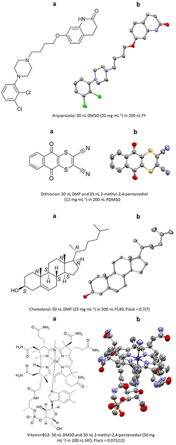
The first report of ENaCt by Hall, Probert and co-workers described the crystallisation and SCXRD analysis of 14 structurally diverse small organic molecules.108 These included APIs (e.g., aripiprazole), agrochemicals (e.g., dithianion), and natural products (e.g., cholesterol, vitamin B12), for a number of which absolute stereochemistry was obtained by anomalous dispersion (Fig. 22).
6.1. ENaCt for the discovery of polymorphs: the 13th polymorph of ROY (R18)
The high-throughput screening capabilities of ENaCt makes it a highly appropriate technique to search experimental crystallisation space for the discovery new crystalline forms, in particular, polymorphs. A polymorphic molecule can exist as two or more crystalline forms, that differ only by the arrangement and/or conformation of the molecules in the crystal lattice.109,110 In the pharmaceutical industry, the discovery of polymorphs of an API are particularly important, as polymorphs have different physical properties which can impact on bioavailability.5-Methyl-2-((2-nitrophenyl)amino)-3-thiophenecarbonitrile is a highly polymorphic synthetic precursor to the antipsychotic drug olanzapine, which is commonly known as ROY due to the red, orange and yellow colouration of its polymorphic forms. In the early work, ROY was studied by ENaCt in an attempt to search for new polymorphs. Prior to this work, twelve polymorphs of ROY were known in the literature, with nine characterised by SCXRD.111–114 Following an extensive screening of crystallisation conditions by ENaCt, all four of the known ROY polymorphs accessible via simple solution-phase crystallisation were obtained (Y, R, ON and ORP). In addition, a new polymorph, R18, was crystallised and successfully analysed by SCXRD, making it the thirteenth polymorph to be discovered and the first ROY polymorph with more than one molecule in the asymmetric unit (Z′ = 2) (Fig. 23).
 | ||
| Fig. 23 (a) Molecular structure of ROY, (b) crystal of ROY (R18) grown via ENaCt (adapted from ref. 108 with permission from Chem, copyright 2020, and (c) displacement ellipsoid representation for R18 (CCDC code: 1944211). Ellipsoids drawn at 50% probability and the second molecule in the asymmetric unit omitted for clarity. | ||
6.2. ENaCt for organic salts: bicyclic triazonium salts
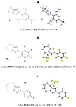
ENaCt has also been applied to the crystallisation of organic salts, soluble in organic solvents. Bicyclic triazolium salts are widely used as precursors for the in situ formation of N-heterocyclic carbene organocatalysts (NHC). Smith, O’Donoghue and co-workers have studied the impact of fused ring size on the rate of proton transfer of bicyclic triazoliums during NHC-catalysed transformations. As part of this work 20 bicyclic triazonium salts were studied, including examination of their crystal structures by SCXRD. The majority of the bicyclic triazonium salts studied were successfully crystallised by classical methods, however the crystallisation of three (2-(2,4,6-triisopropylphenyl)-6,7-dihydro-5H-pyrrolo[2,1-c][1,2,4]triazol-2-ium chloride hydrate, 2-(perfluorophenyl)-5,6,7,8-tetrahydro-[1,2,4]triazolo[4,3-a]pyridine-2-ium tetrafluoro-borate and 2-(4-fluorophenyl)-5,6,7,8,9,9a-hexahydro-4λ4-[1,2,3]triazolo[4,3-a]azepin-2-ium tetrafluoroborate) proved challenging. Through the application of ENaCt, single crystals were obtained in all three cases after 7 days, allowing structural determination by SCXRD (Fig. 24).1156.3. ENaCt for structural elucidation of natural products: hypocrellins
The hypocrellins are a class of perylenequinone fungal natural products, with unique structural, biological, and photochemical properties, in particular with the ability to act as photosensitizers. As part of a study into the biosynthetic relationships of members of hypocrellin and related hypomycin natural products, a series of these natural products were investigated. Isolated natural products are typically very sample limited and, in this case, only a few milligrams were available for analysis. Therefore, ENaCt was used to examine the crystallisation of both ent-shiraiachrome A and hypocrellin B.Samples of ent-shiraiachrome A and hypocrellin B were dissolved in a range of solvents, to form solutions close to their saturation limit. Droplets of these solutions (50 nL) were dispensed into each well of the 96-well glass plate, containing oil droplets (200 nL), and after 14 days, crystals suitable for SCXRD for both analytes were observed.
From 288 individual ENaCt experiments, 96 (33%) gave crystals of ent-shiraiachrome A suitable for SCXRD analysis. ent-Shiraiachrome A crystallised as the DMF solvate, monohydrate, and the resulting crystal structure allowed determination of absolute configuration by anomalous dispersion (Flack = 0.019(5)) (Fig. 25).116
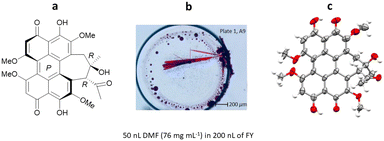 | ||
| Fig. 25 (a) Molecular structure of ent-shiraiachrome A, (b) crystal of ent-shiraiachrome A grown via ENaCt (reproduced from ref. 116 with permission from American Chemical Society, copyright 2022), and (c) displacement ellipsoid representation for ent-shiraiachrome A (CCDC code: 2085795). Ellipsoids drawn at 50% probability, solvent (DMF) and water molecules in the asymmetric unit omitted for clarity. | ||
In the case of hypocrellin B, only 10 (3%) of the 288 individual ENaCt experiments gave crystals suitable for SCXRD. Interestingly, hypocrellin B crystallised as a racemic DMSO solvate containing both the (M)- and (P)-atropisomers (Fig. 26).
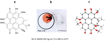 | ||
| Fig. 26 (a) Molecular structure of hypocrellin B, (b) crystal of hypocrellin B grown via ENaCt (reproduced from ref. 116 with permission from American Chemical Society, copyright 2022), and (c) displacement ellipsoid representation for hypocrellin B (CCDC code: 2085796). Ellipsoids drawn at 50% probability, solvent (DMSO) removed for clarity. | ||
6.4. ENaCt for stereochemical determination in medicinal chemistry: SARS-CoV-2 main protease inhibitor
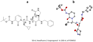
Since the appearance in 2019 of severe acute respiratory syndrome coronavirus 2 (SARS-CoV-2), the causative agent behind the COVID-19 pandemic, considerable efforts have been made in the search for therapeutic agents. Coronavirus main protease (Mpro) is a key enzyme target for molecular inhibitors which can block viral replication. Work by Marsh, Maple, Hilgenfeld and co-workers examined a series α-ketoamides inhibitors of Mpro.117 To support this work, the ENaCt methodology was applied to aid in the determination of their relative and absolute stereochemistry. Single crystals of an example α-ketoamide inhibitor were grown and the absolute stereochemistry determined to be C10(S), C12(S) and C17(R) by anomalous dispersion (Flack: −0.06) (Fig. 27).6.5. Advantages and challenges associated with ENaCt
Encapsulated nanodroplet crystallisation (ENaCt) is a high-throughput automated crystallisation screening method, providing the rapid set-up of hundreds of parallel crystallisation experiments. The method provides control over crystallisation conditions, maximising the likelihood of finding successful crystallisation conditions. Additionally, ENaCt experiments can be undertaken even with low sample requirements, as each individual crystallisation experiment contains only a few micrograms of sample, with only a few milligrams needed for several hundred experiments. Analogous to the microbatch-under oil technique, the analyte is crystallised on its own, thus information about the solid-state packing can be obtained. However, ENaCt is limited to the study of analytes which are solid under ambient conditions.Conclusions and future outlooks
SCXRD is one of the most powerful tools available to researchers in the field of small molecules, providing molecular and structural information at the atomic level resolution, including absolute stereochemistry. Despite the availability of classical methods for the crystallisation of small organic molecules, obtaining suitable single crystals for SCXRD has remained a significant practical challenge. The development of new tools to aid in the growth of single crystals suitable for SCXRD is therefore important for the molecular science community.In this review we have provided an in-depth discussion of four modern crystallisation methods, crystalline sponges, tetraaryladamantane (TAA) inclusion chaperones, microbatch under-oil and encapsulated nanodroplet crystallisation (ENaCt), all of which can enable the study of small molecules by SCXRD.
Neither “the crystalline sponge method” or the use of “tetraaryladamantane based inclusion chaperones” provide direct access to single crystals of the analyte in question, but instead employ a second molecular component to assist in the long-range ordering of the analyte in the solid state. The crystalline sponge utilises single crystals of a preformed MOF, into which the analyte is soaked. The analyte orders itself within the pores of the crystalline sponge, allowing SCXRD analysis. The crystalline sponge method is therefore particularly well suited for the SCXRD analysis of neat liquid analytes, for which few other methods are available, as well as the analysis of larger molecules in solution. The crystal sponge method is potentially limited by the intrinsic properties of the MOF utilised, in that analytes must be small enough to fit within the pores, providing a theoretical upper molecular weight limit, albeit one that has yet to be reached. The use of TAA based inclusion chaperones differs in that the analyte is co-crystallised with the TAA in situ. The TAAs provide a scaffold within the crystal, in which the analyte molecules can be accommodated. TAA based inclusion chaperones have been very successful in the analysis of liquid analytes by SCXRD, and have more recently also proven valuable in the study of a solid analyte. Due to the co-crystallising nature of this technique, and the ability of the TAA chaperones to be matched with the analyte, they have the potential to be applied in the analysis of larger molecules.
“Microbatch under-oil crystallisation” and “encapsulated nanodroplet crystallisation” are both direct crystallisation methods, which employ small scale high-throughput methodologies to allow rapid screening of experimental crystallisation space to provide access to single crystals of the analyte in question. Microbatch under-oil crystallisation, allows for the rapid screening of counterions in the crystallisation of water-soluble organic salts from an aqueous solution. The use of a floating oil layer helps to slow the concentration of the organic salt solution, assisting in controlled single crystal growth of the analyte. To date, microbatch under-oil crystallisation has been solely applied to the crystallisation of a limited number of small molecule organic salts, but this method has significant potential for the crystallisation of a wide range of water-soluble analytes. Similarly, ENaCt also uses oils to aid in the growth of single crystals of an analyte, but is designed for the study of organic-soluble small molecules. A wide range of analytes have been successfully crystallised using ENaCt, including organic-soluble salts, natural products and high molecular weight analytes (≤1355 Da). Both microbatch under-oil crystallisation and ENaCt provide single crystals of the analyte, allowing information about solid-state packing of the analyte to be determined, but limiting the techniques to the crystallisation of analytes which are solid under ambient conditions.
All four modern methods described in this review have been successful in the crystallisation and structural determination of sample limited analytes, where milligrams or less of sample are available, and all provide significant advantages over classical methods. Each of the methods presented herein are best suited to particular analyte types and provide different information on the analyte studied, thus a researcher is encouraged to match the appropriate method to their research question (Table 2).
| Method | Sample preparation | Class of analyte | SCXRD outcomes | ||||||||
|---|---|---|---|---|---|---|---|---|---|---|---|
| Organic soluble | Water soluble | Liquid analytes | Organic salts | Lipophilic log![[thin space (1/6-em)]](https://www.rsc.org/images/entities/char_2009.gif) P > 5 P > 5 |
Sample limited | Natural products | MW > 500 Da | Structural elucidation | Supramolecular chemistry of analyte | Absolute stereochemical elucidation | |
| a Upper molecular weight (MW) likely dependant on MOF pore size. | |||||||||||
| Crystalline Sponge | ✓ | — | ✓ | * | ✓ | ✓ | ✓ | *a | ✓ | — | ✓ |
| TAA based Inclusion Chaperones | ✓ | — | ✓ | * | ✓ | ✓ | ✓ | * | ✓ | — | ✓ |
| Microbatch Under-oil Crystallisation | — | ✓ | — | ✓ | — | ✓ | * | ✓ | ✓ | ✓ | ✓ |
| ENaCt | ✓ | — | — | ✓ | ✓ | ✓ | ✓ | ✓ | ✓ | ✓ | ✓ |
All four of the modern crystallisation methods presented display major advantages, verses classical methods, for the preparation of crystalline materials which enable the analysis of small organic molecules by SCXRD. Each method is best suited for the study of particular molecular classes, but taken together they provide a near universal method for their crystallographic study. We anticipate that uptake of these methods by the small molecule science community will allow the current crystallisation bottleneck to be overcome, through the rapid access to crystalline materials suitable for SCXRD analysis.
Author contributions
Jessica P. Metherall: writing – original draft, writing – review & editing, visualisation Robert C. Carroll: writing – review & editing Simon J. Coles: writing – review & editing, supervision Michael J. Hall: conceptualisation, writing – review & editing, supervision Michael R. Probert: conceptualisation, writing – review & editing, supervision.Conflicts of interest
There are no conflicts to declare.Acknowledgements
Financial support is acknowledged from EPSRC AstraZeneca (2595838) and the EPSRC National Crystallography Service (EP/W02098X/1; EP/W021129/1; EP/T517914/1).Notes and references
- K. N. Trueblood and J. P. Glusker, Crystal Structure Analysis: A Primer, Oxford University Press, Oxford, 2010 Search PubMed.
- A.-H. M. Emwas, Methods Mol. Biol., 2015, 1277, 161–193 CrossRef CAS PubMed.
- J. M. Bijvoet, A. F. Peerdeman and A. J. van Bommel, Nature, 1951, 168, 271–272 CrossRef CAS.
- H. D. Flack and G. Bernardinelli, Acta Crystallogr., 1999, 55, 908–915 CrossRef PubMed.
- H. D. Flack and G. Bernardinelli, Chirality, 2008, 20, 681–690 CrossRef CAS PubMed.
- S. Parsons, Tetrahedron: Asymmetry, 2017, 28, 1304–1313 CrossRef CAS.
- P. G. Jones, Chem. Br., 1981, 17, 222–225 CAS.
- P. van der Sluis, A. M. F. Hezemans and J. Kroon, J. Appl. Crystallogr., 1989, 22, 340–344 CrossRef CAS.
- B. Spingler, S. Schnidrig, T. Todorova and F. Wild, CrystEngComm, 2012, 14, 751–757 RSC.
- S. Jia, Z. Gao, N. Tian, Z. Li, J. Gong, J. Wang and S. Rohani, Chem. Eng. Res. Des., 2021, 166, 268–280 CrossRef CAS.
- L. Shen and M. Dang, CrystEngComm, 2022, 24, 1823–1839 RSC.
- G. F. Arkenbout, Melt Crystallization Technology, Routledge, Boca Raton, 1995 Search PubMed.
- J. Ulrich and T. Stelzer, in Handbook of Industrial Crystallization, ed. A. S. Myerson, D. Erdemir and A. Y. Lee, Cambridge University Press, Cambridge, 3rd edn, 2019, pp. 266–289 Search PubMed.
- C. J. Easley, F. Tong, X. Dong, R. O. Al-Kaysi and C. J. Bardeen, Chem. Sci., 2020, 11, 9852–9862 RSC.
- J. Lombard, V. J. Smith, T. le Roex and D. A. Haynes, CrystEngComm, 2020, 22, 7826–7831 RSC.
- N. Kamali, C. O’malley, M. F. Mahon, A. Erxleben and P. Mcardle, Cryst. Growth Des., 2018, 18, 3510–3516 CrossRef CAS.
- H. N. Holmes, J. Phys. Chem., 1917, 21, 709–733 CrossRef.
- D. K. Kumar and J. W. Steed, Chem. Soc. Rev., 2013, 43, 2080–2088 RSC.
- M. Campione, R. Ruggerone, S. Tavazzi and M. Moret, J. Mater. Chem., 2005, 15, 2437–2443 RSC.
- L. Zhu, R. O. Al-Kaysi and C. J. Bardeen, J. Am. Chem. Soc., 2011, 133, 12569–12575 CrossRef CAS PubMed.
- J. A. K. Howard and M. R. Probert, Science, 2014, 343, 1098–1102 CrossRef CAS PubMed.
- M. Guerain, J. Pharm. Sci., 2020, 109, 2640–2653 CrossRef CAS PubMed.
- J. M. Schall and A. S. Myerson, in Handbook of Industrial Crystallization, ed. A. S. Myerson, D. Erdemir and A. Y. Lee, Cambridge University Press, Cambridge, 3rd edn, 2019, pp. 1–31 Search PubMed.
- J. W. Mullin, Crystallization, Butterworth-Heinemann, Oxford, 2001 Search PubMed.
- G. Coquerel, Chem. Soc. Rev., 2014, 43, 2286–2300 RSC.
- T. L. Threlfall and S. J. Coles, CrystEngComm, 2016, 18, 369–378 RSC.
- D. Erdemir, A. Y. Lee and A. S. Myerson, Acc. Chem. Res., 2009, 42, 621–629 CrossRef CAS PubMed.
- R. Tamura and M. Miyata, Advances in Organic Crystal Chemistry: Comprehensive Reviews, Springer, Japan, New York, 2015 Search PubMed.
- P. Crafts, Comput. Aided Chem. Eng., 2007, 23, 23–85 CAS.
- P. P. Nievergelt and B. Spingler, CrystEngComm, 2016, 19, 142–147 RSC.
- M. J. Wen, M. T. Jackson and C. M. Garner, Dalton Trans., 2019, 48, 11575–11582 RSC.
- H. J. M. Kramer, R. Lakerveld and H. Kong, Selection and Design of Industrial Crystallizers, Cambridge University Press, Cambridge, 2019 Search PubMed.
- Z. Gao, S. Rohani, J. Gong and J. Wang, Engineering, 2017, 3, 343–353 CrossRef.
- S. L. Morissette, Ö. Almarsson, M. L. Peterson, J. F. Remenar, M. J. Read, A. V. Lemmo, S. Ellis, M. J. Cima and C. R. Gardner, Adv. Drug Delivery Rev., 2004, 56, 275–300 CrossRef CAS PubMed.
- Z. K. Nagy, G. Fevotte, H. Kramer and L. L. Simon, Chem. Eng. Res. Des., 2013, 91, 1903–1922 CrossRef CAS.
- Y. Yang and Z. K. Nagy, Chem. Eng. Sci., 2015, 127, 362–373 CrossRef CAS.
- N. Zigon, V. Duplan, N. Wada and M. Fujita, Angew. Chem., Int. Ed., 2021, 60, 25204–25222 CrossRef CAS PubMed.
- Y. Inokuma, T. Arai and M. Fujita, Nat. Chem., 2010, 2, 780–783 CrossRef CAS PubMed.
- Y. Inokuma, S. Yoshioka, J. Ariyoshi, T. Arai, Y. Hitora, K. Takada, S. Matsunaga, K. Rissanen and M. Fujita, Nature, 2013, 495, 461–466 CrossRef CAS PubMed.
- B. F. Hoskins and R. Robson, J. Am. Chem. Soc., 1989, 111, 5962–5964 CrossRef CAS.
- B. F. Hoskins and R. Robson, J. Am. Chem. Soc., 1990, 112, 1546–1554 CrossRef CAS.
- O. M. Yaghi, N. W. Ockwig, H. K. Chae, M. Eddaoudi and J. Kim, Nature, 2003, 423, 705–714 CrossRef CAS PubMed.
- H. C. Zhou, J. R. Long and O. M. Yaghi, Chem. Rev., 2012, 112, 673–674 CrossRef CAS PubMed.
- Q. Wang and D. Astruc, Chem. Rev., 2020, 120, 1438–1511 CrossRef CAS PubMed.
- A. J. Howarth, Y. Liu, P. Li, Z. Li, T. C. Wang, J. T. Hupp and O. K. Farha, Nat. Rev. Mater., 2016, 1, 1–15 Search PubMed.
- Z. Chen, K. O. Kirlikovali, K. B. Idrees, M. C. Wasson and O. K. Farha, Chem, 2022, 8, 693–716 CAS.
- H. He, J. A. Perman, G. Zhu and S. Ma, Small, 2016, 12, 6309–6324 CrossRef CAS PubMed.
- W. Wang, X. Xu, W. Zhou and Z. Shao, Adv. Sci., 2017, 4, 1600371 CrossRef PubMed.
- M.-X. Wu, Y.-W. Yang, M.-X. Wu and Y.-W. Yang, Adv. Mater., 2017, 29, 1–20 Search PubMed.
- S. Rojas, I. Colinet, D. Cunha, T. Hidalgo, F. Salles, C. Serre, N. Guillou and P. Horcajada, ACS Omega, 2018, 3, 2994–3003 CrossRef CAS PubMed.
- R. Ou, H. Zhang, V. X. Truong, V. X. Truong, L. Zhang, H. M. Hegab, L. Han, J. Hou, X. Zhang, A. Deletic, L. Jiang, G. P. Simon and H. Wang, Nat. Sustainability, 2020, 3, 1052–1058 CrossRef.
- M. J. Uddin, R. E. Ampiaw and W. Lee, Chemosphere, 2021, 284, 131314 CrossRef CAS PubMed.
- H. Xu, C. S. Cao, X. M. Kang and B. Zhao, Dalton Trans., 2016, 45, 18003–18017 RSC.
- B. Li, X. Dong, H. Wang, D. Ma, K. Tan, S. Jensen, B. J. Deibert, J. Butler, J. Cure, Z. Shi, T. Thonhauser, Y. J. Chabal, Y. Han and J. Li, Nat. Commun., 2017, 8, 1–9 CrossRef PubMed.
- H. Kim, H. Chun, G. H. Kim, H. S. Lee and K. Kim, Chem. Commun., 2006, 2759–2761 RSC.
- K. Ikemoto, Y. Inokuma and M. Fujita, Angew. Chem., Int. Ed., 2010, 49, 5750–5752 CrossRef CAS PubMed.
- Y. Inokuma, M. Kawano and M. Fujita, Nat. Chem., 2011, 3, 349–358 CrossRef CAS PubMed.
- K. Ikemoto, Y. Inokuma and M. Fujita, J. Am. Chem. Soc., 2011, 133, 16806–16808 CrossRef CAS PubMed.
- M. Hoshino, A. Khutia, H. Xing, Y. Inokuma and M. Fujita, IUCrJ, 2016, 3, 139–151 CrossRef CAS PubMed.
- O. Ohmori, M. Kawano and M. Fujita, J. Am. Chem. Soc., 2004, 126, 16292–16293 CrossRef CAS PubMed.
- Y. Inokuma, S. Yoshioka, J. Ariyoshi, T. Arai and M. Fujita, Nat. Protoc., 2014, 9, 246–252 CrossRef CAS PubMed.
- G. W. Waldhart, N. P. Mankad and B. D. Santarsiero, Org. Lett., 2016, 18, 6112–6115 CrossRef CAS PubMed.
- T. R. Ramadhar, S. L. Zheng, Y. S. Chen and J. Clardy, Acta Crystallogr., 2015, 71, 46–58 CrossRef CAS PubMed.
- Y. Inokuma, K. Matsumura, S. Yoshioka and M. Fujita, Chem. – Asian J., 2017, 12, 208–211 CrossRef CAS PubMed.
- F. Habib, D. A. Tocher and C. J. Carmalt, Mater. Today: Proc., 2022, 56, 3766–3773 Search PubMed.
- K. Rissanen, Chem. Soc. Rev., 2017, 46, 2638–2648 RSC.
- L. M. Hayes, C. E. Knapp, K. Y. Nathoo, N. J. Press, D. A. Tocher and C. J. Carmalt, Cryst. Growth Des., 2016, 16, 3465–3472 CrossRef CAS.
- M. Hoshino, A. Khutia, H. Xing, Y. Inokuma and M. Fujita, IUCrJ, 2016, 3, 139–151 CrossRef CAS PubMed.
- T. R. Ramadhar, S. L. Zheng, Y. S. Chen and J. Clardy, Chem. Commun., 2015, 51, 11252–11255 RSC.
- A. D. Cardenal and T. R. Ramadhar, ACS Cent. Sci., 2021, 7, 406–414 CrossRef CAS PubMed.
- R. D. J. Lunn, D. A. Tocher, P. J. Sidebottom, M. G. Montgomery, A. C. Keates and C. J. Carmalt, Cryst. Growth Des., 2021, 21, 3036 CrossRef PubMed.
- S. Yoshioka, Y. Inokuma, M. Hoshino, T. Sato and M. Fujita, Chem. Sci., 2015, 6, 3765–3768 RSC.
- K. Li, D. S. Yang, X. F. Gu and B. Di, Fitoterapia, 2019, 134, 135–140 CrossRef CAS PubMed.
- J. Chen, T. Kikuchi, K. Takagi, H. Kiyota, K. Adachi, T. Mitsuhashi and M. Fujita, Chem. Lett., 2021, 51, 85–87 CrossRef.
- Y. Inokuma, T. Ukegawa, M. Hoshino and M. Fujita, Chem. Sci., 2016, 7, 3910–3914 RSC.
- M. Kawahata, S. Komagawa, K. Ohara, M. Fujita and K. Yamaguchi, Tetrahedron Lett., 2016, 57, 4633–4636 CrossRef CAS.
- Y. Matsuda, T. Akaaki Mitsuhashi, S. Lee, A. Hoshino, A. Mori, M. Okada, H. Zhang, F. Hayashi, H. Zhang and M. Fujita, Angew. Chem., Int. Ed., 2016, 55, 5785–5788 CrossRef CAS PubMed.
- S. Urban, R. Brkljača, M. Hoshino, S. Houkou Lee and M. Fujita, Angew. Chem., Int. Ed., 2016, 55, 2678–2682 CrossRef CAS PubMed.
- N. Zigon, M. Hoshino, S. Yoshioka, Y. Inokuma and M. Fujita, Angew. Chem., Int. Ed., 2015, 54, 9033–9037 CrossRef CAS PubMed.
- R. D. J. Lunn, D. A. Tocher, P. J. Sidebottom, M. G. Montgomery, A. C. Keates and C. J. Carmalt, Cryst. Growth Des., 2021, 21, 3024–3036 CrossRef CAS PubMed.
- N. Wada, R. D. Kersten, T. Iwai, S. Lee, F. Sakurai, T. Kikuchi, D. Fujita, M. Fujita and J.-K. Weng, Angew. Chem., Int. Ed., 2018, 57, 3671–3675 CrossRef CAS PubMed.
- F. Sakurai, A. Khutia, T. Kikuchi, M. Fujita and F. Sakurai, Chem. – Eur. J., 2017, 23, 15035–15040 CrossRef CAS PubMed.
- F. Habib, D. A. Tocher, N. J. Press and C. J. Carmalt, Microporous Mesoporous Mater., 2020, 308, 110548 CrossRef CAS.
- N. Zigon, T. Kikuchi, J. Ariyoshi, Y. Inokuma and M. Fujita, Chem. – Asian J., 2017, 12, 1057–1061 CrossRef CAS PubMed.
- L. Rosenberger, C. von Essen, A. Khutia, C. Kühn, K. Urbahns, K. Georgi, R. W. Hartmann and L. Badolo, Drug Metab. Dispos., 2020, 48, 587–593 CrossRef CAS PubMed.
- G. Brunet, D. A. Safin, K. Robeyns, G. A. Facey, I. Korobkov, Y. Filinchuk and M. Murugesu, Chem. Commun., 2017, 53, 5645–5648 RSC.
- L. Katz and R. H. Baltz, J. Ind. Microbiol. Biotechnol., 2016, 43, 155–176 CrossRef CAS PubMed.
- Y. Hitora, K. Takada, S. Okada and S. Matsunaga, Tetrahedron, 2011, 67, 4530–4534 CrossRef CAS.
- A. L. Spek, Acta Crystallogr., Sect. C: Struct. Chem., 2015, 71, 9–18 CrossRef CAS PubMed.
- Y. Inokuma, S. Yoshioka, J. Ariyoshi, T. Arai, Y. Hitora, K. Takada, S. Matsunaga, K. Rissanen and M. Fujita, Nature, 2013, 501, 262 CrossRef CAS.
- A. L. Spek, Inorg. Chim. Acta, 2018, 470, 232–237 CrossRef CAS.
- Y. Taniguchi, T. Kikuchi, S. Sato, M. Fujita, Y. Taniguchi, T. Kikuchi, S. Sato and M. Fujita, Chem. – Eur. J., 2021, 28, 1–5 Search PubMed.
- S. Øien-ØDegaard, G. C. Shearer, D. S. Wragg and K. P. Lillerud, Chem. Soc. Rev., 2017, 46, 4867–4876 RSC.
- S. Lee, E. A. Kapustin and O. M. Yaghi, Science, 2016, 353, 808–811 CrossRef CAS PubMed.
- A. Schwenger, W. Frey and C. Richert, Eur. J. Chem., 2015, 21, 8781–8789 CrossRef CAS PubMed.
- A. Schwenger, W. Frey and C. Richert, Angew. Chem., Int. Ed., 2016, 55, 13706–13709 CrossRef CAS PubMed.
- P. E. Alexandre, A. Schwenger, W. Frey and C. Richert, Eur. J. Chem., 2017, 23, 9018–9021 CrossRef CAS PubMed.
- C. Richert and F. Krupp, Synlett, 2017, 1763–1766 CAS.
- F. Krupp, S. He, W. Frey and C. Richert, Synlett, 2018, 1707–1710 CAS.
- F. Krupp, W. Frey and C. Richert, Angew. Chem., Int. Ed., 2020, 59, 15875–15879 CrossRef CAS PubMed.
- F. Krupp, M.-I. Picher, W. Frey, B. Plietker and C. Richert, Synlett, 2021, 350–353 CAS.
- F. Rami, J. Nowak, F. Krupp, W. Frey and C. Richert, Beilstein J. Org. Chem., 2021, 17, 1476–1480 CrossRef CAS PubMed.
- M. Babor, P. P. Nievergelt, J. Č. Ejka, V. Zvoníček and B. Spingler, IUCrJ, 2019, 6, 145–151 CrossRef CAS PubMed.
- L. Kumar, A. Amin and A. K. Bansal, Drug Discovery Today, 2007, 12, 1046–1053 CrossRef CAS PubMed.
- P. P. Nievergelt, M. Babor, J. Cejka and B. Spingler, Chem. Sci., 2018, 9, 3716–3722 RSC.
- SCOGS (Select Committee on GRAS Substances), https://www.cfsanappsexternal.fda.gov/scripts/fdcc/?set=SCOGS, (accessed 30 November 2022).
- G. S. Paulekuhn, J. B. Dressman and C. Saal, J. Med. Chem., 2007, 50, 6665–6672 CrossRef CAS PubMed.
- A. R. Tyler, R. Ragbirsingh, C. J. McMonagle, P. G. Waddell, S. E. Heaps, J. W. Steed, P. Thaw, M. J. Hall and M. R. Probert, Chem, 2020, 6, 1755–1765 CAS.
- D. J. W. Grant, Theory and origin of polymorphism, Marcel Dekker, New York, 1999 Search PubMed.
- A. J. Cruz-Cabeza and J. Bernstein, Chem. Rev., 2014, 114, 2170–2191 CrossRef CAS PubMed.
- S. Chen, I. A. Guzei and L. Yu, J. Am. Chem. Soc., 2005, 127, 9881–9885 CrossRef CAS PubMed.
- M. Tan, A. G. Shtukenberg, S. Zhu, W. Xu, E. Dooryhee, S. M. Nichols, M. D. Ward, B. Kahr and Q. Zhu, Faraday Discuss., 2018, 211, 477–491 RSC.
- K. S. Gushurst, J. Nyman and S. X. M. Boerrigter, CrystEngComm, 2019, 21, 1363–1368 RSC.
- J. Nyman, L. Yu and S. M. Reutzel-Edens, CrystEngComm, 2019, 21, 2080–2088 RSC.
- J. Zhu, I. Moreno, P. Quinn, D. S. Yufit, L. Song, C. M. Young, Z. Duan, A. R. Tyler, P. G. Waddell, M. J. Hall, M. R. Probert, A. D. Smith and A. C. O’Donoghue, J. Org. Chem., 2022, 87, 4241–4253 CrossRef CAS PubMed.
- Z. Y. Al Subeh, A. L. Waldbusser, H. A. Raja, C. J. Pearce, K. L. Ho, M. J. Hall, M. R. Probert, N. H. Oberlies and S. Hematian, J. Org. Chem., 2022, 87, 2697–2710 CrossRef CAS PubMed.
- M. S. Cooper, L. Zhang, M. Ibrahim, K. Zhang, X. Sun, J. Röske, M. Göhl, M. Brönstrup, J. K. Cowell, L. Sauerhering, S. Becker, L. Vangeel, D. Jochmans, J. Neyts, K. Rox, G. P. Marsh, H. J. Maple and R. Hilgenfeld, J. Med. Chem., 2022, 65, 13328–13342 CrossRef CAS PubMed.
| This journal is © The Royal Society of Chemistry 2023 |


