Dual additive of lithium titanate and sulfurized pyrolyzed polyacrylonitrile in sulfur cathode for high rate performance in lithium–sulfur battery†
Received
14th September 2022
, Accepted 1st December 2022
First published on 8th December 2022
Abstract
Lithium–Sulfur (Li–S) batteries have attracted much attention as next-generation batteries due to their high theoretical energy density. However, lithium polysulfide generated during the discharge loses intimate electrical contact with the carbon matrix due to its high solubility in the electrolyte, causing a high charge transfer resistance and slow redox kinetics for the discharge reactions, resulting in a low rate capability. A cathode additive having a strong chemical adsorbing site toward the polysulfide can effectively inhibit their dissolution. We now report a dual additive of lithium titanium oxide (LTO) and sulfurized polyacrylonitrile (SPAN). LTO provides a rapid charge transfer and a fast Li+ ion transfer in the cathode. On the other hand, SPAN helps to enhance the polysulfide adsorption capability. This dual additive system synergistically supplies the cathode with a strong polysulfide adsorption capability and fast redox kinetics. As a result, the dual additive exhibits high discharge capacities of 1430 mA h g−1 at 0.1C and 1200 mA h g−1 at 0.5C at the high-sulfur-loading cathode of 5.0 mg cm−2. Our findings demonstrated the manufacturing of the cathode with a strong polysulfide adsorption capability and a fast redox reaction which could then effectively improve the rate performance of the Li–S batteries.
1. Introduction
Lithium–Sulfur (Li–S) batteries have attracted much attention as one of the next-generation batteries due to their higher energy density versus that of Li-ion batteries. Sulfur as the cathode's active material has a high theoretical capacity of 1675 mA h g−1, and has characteristics of a low material cost and is environmentally friendly.1 However, the Li–S batteries are still facing severe issues; i.e., a low cycle stability and poor rate capability.
The electrochemical reaction during discharging in the S cathode is distinguished by four stages represented by eqn (I)–(IV).2 Sulfur is reduced to lithium polysulfide (Li2Sx: 4 ≦ x ≦ 8), then Li2S4 is reduced to Li2S2 and/or Li2S. The Li2S2 and Li2S are oxidized to sulfur through lithium polysulfide during charging.
| | | S8 + 2Li+ + 2e− → Li2S8 | (I) |
| | | Li2S8 + 2Li+ + 2e− → 4Li2S6 | (II-i) |
| | | 2Li2S6 + 2Li+ + 2e− → 3Li2S4 | (II-ii) |
| | | Li2S4 + 2Li+ + 2e− → 2Li2S2 | (III-i) |
| | | Li2S4 + 6Li+ + 6e− → 6Li2S | (III-ii) |
| | | Li2S2 + 2Li+ + 2e− → 2Li2S | (IV) |
Lithium polysulfide easily dissolves into a liquid electrolyte during the discharge. In the most recently reported electrolyte (1 mol dm−3 lithium bis (trifluoromethanesulfonyl) imide (LiTFSI) in a mixture of 1,2-dimethoxyethane (DME) and 1,3-dioxolane (DOL) at a volume ratio of 1![[thin space (1/6-em)]](https://www.rsc.org/images/entities/char_2009.gif) :1) for the Li–S batteries, it was demonstrated that the sulfur-based components of ca. 44% were dissolved from the cathode into the electrolyte even at the end of the first discharge, indicating a very high solubility of the polysulfide.3 The dissolved polysulfide loses intimate electrical contact with the carbon matrix, leading to a high charge transfer resistance and slow redox kinetics of the discharge reactions.4 In addition, the dissolved polysulfide migrates through the liquid electrolyte and reacts with the Li metal anode during charging causing anode degradation and a low coulombic efficiency.5 This behavior is well known as “the redox shuttle”.6 Therefore, the strategy for the suppression of the polysulfide dissolution is critical to improving the battery performance.
:1) for the Li–S batteries, it was demonstrated that the sulfur-based components of ca. 44% were dissolved from the cathode into the electrolyte even at the end of the first discharge, indicating a very high solubility of the polysulfide.3 The dissolved polysulfide loses intimate electrical contact with the carbon matrix, leading to a high charge transfer resistance and slow redox kinetics of the discharge reactions.4 In addition, the dissolved polysulfide migrates through the liquid electrolyte and reacts with the Li metal anode during charging causing anode degradation and a low coulombic efficiency.5 This behavior is well known as “the redox shuttle”.6 Therefore, the strategy for the suppression of the polysulfide dissolution is critical to improving the battery performance.
To inhibit dissolution of the polysulfide, metal-based compounds have been introduced as cathode additives, for example, metal carbides, metal oxides, and metal sulfides.7–9 They work as chemical adsorbents of the polysulfide due to the interaction between the polysulfide and metallic elements (e.g., vanadium,8 aluminum,10 titanium,11 and cobalt4). For instance, LiNi0.8Co0.15Al0.05O2 (NCA) demonstrated a high adsorption capability of the polysulfide due to the formation of strong Li–O and Co–S bonds between NCA and the polysulfide, resulting in a high rate performance and superior cycle stability.10 Some other metal-based components (e.g., CoS2,4 LiFePO4 (LFP),12 and BaTiO313) were added to the cathode in the Li–S batteries. Lithium titanium oxide (LTO), which has been extensively investigated as an anode material for Li-ion batteries, also functions as a polysulfide adsorbent due to an interaction between the polar parts (such as titanium and oxygen) and the polysulfide.14–18 For instance, a separator modified by LTO and graphene mixture showed blocking the migration of the polysulfide to the Li anode side, improving the cycle performance of Li–S batteries.15 More importantly, LTO acts as not only a Li+ ion conductor but also an electronic conductor, providing a catalytic function for the sulfur cathode. T. Zeng et al., demonstrated a novel composite composed of LTO and carbon material as a sulfur host, resulting in that LTO plays an important role in enhancing redox reaction in a sulfur cathode.18
To develop high energy density (300–500 W h kg−1) Li–S batteries, a high-sulfur-loading cathode with more than 5.0 mg cm−2 is necessary.19 However, the rate performance in a high loading cathode is not satisfactory.20–22 We now report that the rate performance of the Li–S batteries is dramatically improved by applying a novel dual-additive system of LTO and sulfurized polyacrylonitrile (SPAN) for a high-sulfur-loading cathode. SPAN, which is known as a promising cathode material for next-generation batteries, is an organic compound synthesized by the reaction between sulfur and polyacrylonitrile (PAN) during heating.23 Researchers have demonstrated that nitrogen-doped materials have strong polysulfide adsorption capability due to a strong interaction between a nitrogen part and the polysulfide.24–26 Particularly, pyrrolic-N and pyridinic-N are better optimal structures for capturing the polysulfide, contributing to the improvement of the battery performance.26 It is expected to enhance the polysulfide adsorption capability because SPAN is constructed with an abundant nitrogen source with pyrrolic-N and pyridinic-N. The dual additive of LTO and SPAN provides the strong adsorption capability and acceleration of the redox reaction in the cathode, resulting in high discharge capacities even for a high-loading sulfur. Moreover, the cathodes with the different ratios of LTO and SPAN were investigated for their electrochemical properties.
2. Experimental
2.1 Lithium titanium oxide and sulfurized polyacrylonitrile
Lithium titanium oxide (LTO/Li4Ti5O12, D50 6 μm, ca. 3 ± 1 m2 g−1) was purchased from Wako Co., Ltd. Sulfurized polyacrylonitrile (SPAN/D50 8 μm, ca. 9 m2 g−1) was provided by ADEKA Co., Ltd.
2.2 Visual adsorption test for lithium polysulfide and characterization
The adsorption capability for lithium polysulfide was evaluated for LTO and SPAN. Before the adsorption test, all the samples were dried under vacuum at 100 °C for 12 hours in argon gas. A 5 mmol dm−3 Li2S6 solution (2 mL) was prepared by mixing sulfur and lithium sulfide (Li2S, Sigma-Aldrich) at the molar ratio of 5:1 in DME based on a previous report.27 After soaking of the samples with equal surface area (0.325 m2) in the Li2S6 solution for 7 days, the colors of the solutions were compared. Raman measurement (NRS-4100, JASCO Corp.) using a 532 nm laser was conducted to investigate the solution structures. To identify the surface chemical components before/after soaking in the Li2S6 solution, the samples were analyzed by X-ray photoelectron spectroscopy (XPS; JPS-9010MX, JEOL Co., Ltd) with an Al Kα X-ray source after drying. The samples were placed in the XPS chamber by a transfer vessel without exposure to air.
2.3 Fabrication of S/C composite cathode
The colloidal sulfur (S) (powder, ≧99.00%, Sigma-Aldrich)/porous carbon (CNovel/MH-00, Toyo Tanso Co.) composite was prepared by a typical melt-diffusion strategy.28 S and CNovel in the weight ratio of 7:3 were mixed then heated at 155 °C for 12 h in flowing argon gas to incorporate the S into the CNovel. The weight ratio of S in the S/C Novel composite was determined to be 70% by a thermogravimetric analysis (TGA) as shown in Fig. S1 (ESI†). The S/CNovel composite, AB, and styrene-butadiene rubber (SBR/TRD2001, JSR Co., Ltd) were mixed with an aqueous dispersion (TUBALLTM BATT H2O 0.4%, OCSiAl Europe SARL) containing 0.4% single-wall carbon nanotubes (SWCNT) and 0.6% carboxymethyl cellulose (CMC). LTO and SPAN were then added at varying weight ratios. The cathodes were fabricated by mixing the S/CNovel composite, AB, SWCNT, SBR/CMC, LTO, and SPAN in the weight ratio of 85:1:2:5:X:Y, as shown in Table 1. For example, the 6:1 wt% LTO:SPAN cathode contained LTO and SPAN in the weight ratio of 6:1. The obtained slurry was coated on carbon-coated aluminum foil and dried at 60 °C under vacuum. The composite cathode was compressed and cut in a circular pattern with a 14 mm diameter. The weights of S per unit area were 5.0 mg cm−2 (8.4 mA h cm−2) and 7.2 mg cm−2 (12.1 mA h cm−2). The uniform distribution of LTO and SPAN was proven by elemental mapping images of titanium and nitrogen using energy-dispersive X-ray spectrometry (JSM-6490A, JEOL Co., Ltd), as shown in Fig. S2 (ESI†).
Table 1 The composition of the composite cathodes
| Cathode material ratio/wt% |
Label |
| S/C Novel:AB:SWCNT:CMC/SBR |
w/o additive |
| 92:1:2:5 |
| S/C Novel:AB:SWCNT:CMC/SBR:LTO |
7 wt% LTO |
| 85:1:2:5:7 |
| S/C Novel:AB:SWCNT:CMC/SBR:SPAN |
7 wt% SPAN |
| 85:1:2:5:7 |
| S/C Novel:AB:SWCNT:CMC/SBR:LTO:SPAN |
6:1 wt% LTO:SPAN |
| 85:1:2:5:X:Y (X:Y = 6:1, 5:2, 4:3, 3:4) |
5:2 wt% LTO:SPAN |
| 4:3 wt% LTO:SPAN |
| 3:4 wt% LTO:SPAN |
2.4 Cell assembly and electrochemical performance test
The Li–S cells were assembled using the 2032-type coin cell type (Hosen Co., Ltd) containing the composite cathode, a three-dimensionally ordered macroporous polyimide separator (3DOM PI separator, Tokyo Ohka Kogyo Co., Ltd)29,30 filled with the electrolyte, and Li foil anode (Honjo Metal Co., Ltd) in a glove box with an argon atmosphere. The electrolyte was prepared by dissolving 1 mol dm−3 LiTFSI (Kishida Chemical Co., Ltd) into the solution of DOL (Sigma-Aldrich) and DME (Sigma-Aldrich) (1:1 by volume) with 1 wt% lithium nitrate (LiNO3, Sigma-Aldrich). The galvanostatic charge–discharge test was conducted by a TOCAT-3000U (Toyo System Co., Ltd). To study the redox reactivity of lithium polysulfide in the additives, cyclic voltammetry was conducted within the potential range of −1.2 V to 1.2 V at the sweep rate of 0.1 mV s−1 for the symmetric cells. LTO, SPAN, carbon, and CMC (MAC350HC, Nippon Paper Industries Co., Ltd) were mixed in different weight ratios of X:45:10 in deionized water (X = 45 wt% LTO, 45 wt% SPAN, and 22.5:22.5 wt% LTO:SPAN). A 0.15 mol dm−3 Li2S8 DOL/DME (1:1 in volume) solution containing LiTFSI was used for the symmetric cells. Electrochemical impedance spectroscopy (EIS; SP-200, Bio-Logic Sci. Inst.) was conducted in the frequency range from 3 MHz to 100 mHz with an amplitude of 10 mV. The test temperature of all the electrochemical tests was 60 °C.
3. Results and discussion
3.1 Adsorption capability toward lithium polysulfide in LTO and SPAN
The enhancement of the adsorption capability toward lithium polysulfide is also very important to improve the Li–S battery performance. To investigate the polysulfide adsorption capability of the additives (i.e., LTO, SPAN, and dual additive (LTO + SPAN)), a visual adsorption test was evaluated using the additives with an equal surface area of 0.325 m2 added to the 5 mmol dm−3 Li2S6/DME solution. AB was also compared as a conventional carbon material. Fig. 1 shows a photograph of the solutions after 7 days of soaking each sample. Note that the LTO and SPAN were mixed in the area ratio of 1:1 in LTO + SPAN. The solutions containing LTO or SPAN were clear compared to AB, indicating that LTO and SPAN have a higher adsorption capability for the polysulfide compared to AB. Based on the results of Raman spectroscopy of the solutions after the adsorption test, the peaks attributed to the polysulfide (ca. 470 and 530 cm−2) decreased in the solutions with LTO or SPAN (Fig. S3, ESI†). Especially, SPAN completely decolorized Li2S6/DME, meaning that SPAN has a stronger adsorption for the polysulfide than that of LTO. Moreover, it can be seen that the solution containing LTO + SPAN was also apparently clear. Based on the results of the adsorption tests, it is expected that LTO can act as a higher adsorbent for the polysulfide than the conventional carbon material, improving the electrochemical performance of the sulfur cathode, as described in previous reports.14–18 However, only adding LTO may not be enough to adsorb the dissolved polysulfide. Insufficient adsorption leads to generating unreacted polysulfide due to poor intimate electrical contact with the carbon matrix, resulting in low electrochemical performances.4 It is suggested that the addition of a strong adsorbent, such as SPAN, helps to enhance the adsorption capability of the polysulfide.
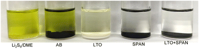 |
| | Fig. 1 A photograph of the Li2S6/DME solutions in the visual adsorption test. Samples (i.e., AB, LTO, SPAN, and LTO + SPAN) with an equal surface area were added to the 5 mmol dm−3 Li2S6/DME solution with storage for 7 days. Note that LTO and SPAN were mixed in the weight ratio of 1:1 in LTO + SPAN. | |
The chemical compositions of the LTO and SPAN surfaces before/after the polysulfide adsorption test were analyzed by XPS (Fig. 2a and b and Table S1, ESI†). In the Ti2p and S2p spectra of the LTO surface, the peaks assigned to the Ti–S bond were detected after the adsorption test,31 as shown in Fig. 2a. In addition, the other peaks attributed to the polysulfide (i.e., sulfate, S–S, and Li–S) were observed after immersing in the Li2S6/DME solution, indicating that the polysulfide was adsorbed on the LTO surface. In the N1s spectra of the SPAN surface, the broad peak, which was paired with pyridinic-N (398.4 eV), pyrrolic-N (399.8 eV), and graphitic-N (401.5 eV), was observed before/after the adsorption, as shown in Fig. 2b.26,32 It can be seen that peak intensity after the adsorption test was weaker than that before, suggesting that the polysulfide was adsorbed on the SPAN surface due to the interaction between a nitrogen part and the polysulfide.24 In addition, from the atomic ratio obtained by XPS, the S content on the SPAN surface increased after the polysulfide adsorption test (Table S1, ESI†). From the XPS results, it was confirmed that the polysulfide was adsorbed on the surface of each additive.
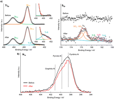 |
| | Fig. 2 (a) XPS spectra of Ti2p, and S2p of LTO before/after the polysulfide adsorption test. (b) XPS spectra of Li1s of SPAN before/after the polysulfide adsorption test. | |
3.2 Redox reactivity of lithium polysulfide in LTO and SPAN
To investigate the redox reactivity of lithium polysulfide in LTO and SPAN, cyclic voltammetry (CV) was conducted using symmetric cells with a solution containing lithium polysulfide (0.15 mol dm−3 Li2S8/DOL:DME). This CV test with the symmetric cell is a more direct method to evaluate the redox kinetics of the polysulfide on an electrode.33 Three test electrodes (1.1 mg cm−2) were prepared by mixing LTO, SPAN, carbon, and CMC in different weight ratios. Fig. 3a shows the cyclic voltammograms. The solution without Li2S8 hardly indicated a current response, meaning that LTO and SPAN provided extremely low capacitive contributions. On the other hand, much higher current cathodic/anodic peaks were observed at −0.9 V, −0.3 V, 0.3 V, and 0.9 V in the solution containing Li2S8 related to the redox reaction of the polysulfide. It was assumed that the cathodic peaks (−0.9 V and −0.3 V) and the anodic peaks (0.3 V and 0.9 V) are attributed to the reduction from Li2S8 to Li2S (or Li2S2) and the oxidation from Li2S (or Li2S2) to sulfur on the working electrode, respectively.34,35 As shown in Fig. 3a, the current response in the LTO is higher than that in the SPAN, indicating that LTO can promote the redox reaction of the polysulfide compared to SPAN. Such accelerated redox reactivity of the polysulfide in LTO was also verified by EIS of the symmetric cells. Fig. 3b shows Nyquist plots of the symmetric cells and an equivalent circuit model for the determination of the resistance component. A depressed semicircle is attributed to the charge transfer resistance (Rct) at the interface between an electrode and the polysulfide.4,10 It can be seen that Rct in LTO (0.617 Ω) is lower than that in SPAN (0.947 Ω), demonstrating that LTO provides a rapid charge transfer, which contributes to facilitating the redox reactivity of the polysulfide.10 The high charge transfer in SPAN may be caused by a low intrinsic electronic conductivity of SPAN.36 More interestingly, the dual additive (LTO + SPAN) showed the highest current response among them. As shown in Fig. 3b, considering that Rct in LTO + SPAN (0.698 Ω) is almost equivalent to that of LTO, the fast redox kinetics in LTO + SPAN could be attributed to the enhanced adsorption capability for the polysulfide in the electrode by mixing with SPAN. It was demonstrated that the adsorption capability was enhanced by mixing LTO with SPAN in the adsorption test (Fig. 1a). Sufficient adsorption provides enhancement of the intimate electrical contact between the polysulfide and the carbon matrix in the electrode, demonstrating faster redox kinetics in the LTO + SPAN.4,33
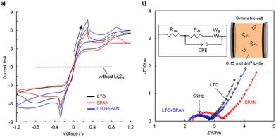 |
| | Fig. 3 (a) Cyclic voltammograms of symmetric cells using different electrodes with and without Li2S8. Cyclic voltammetry was conducted at 0.1 mV s−1 between −1.2 V and 1.2 V. (b) Nyquist plots of symmetric cells using different electrodes and an equivalent circuit model. LTO, SPAN, carbon, and CMC were mixed in different weight ratios of X![[thin space (1/6-em)]](https://www.rsc.org/images/entities/i_char_2009.gif) :45:10 (X = LTO 45 wt%, SPAN 45 wt%, and LTO:SPAN 22.5:22.5 wt%). EIS was conducted in the frequency range of 3 MHz to 0.1 Hz with an amplitude of 10 mV at 60 °C. :45:10 (X = LTO 45 wt%, SPAN 45 wt%, and LTO:SPAN 22.5:22.5 wt%). EIS was conducted in the frequency range of 3 MHz to 0.1 Hz with an amplitude of 10 mV at 60 °C. | |
3.3 Li+ ion diffusion coefficient
It is known that the Li+ ion coefficient (DLi+) is a critical factor for understanding the electrochemical properties.37–39DLi+ is distinguished from (1) the Li+ ion diffusion transfer in an electrode, (2) the Li+ ion diffusion transfer for the lithiation and delithiation processes in the active material, and (3) the Li+ ion diffusion transfer in a separator filling with an electrolyte. The CV test was conducted using the Li–S cells containing cathodes with the different additives and DLi+ was determined according to the Randles–Sevcik eqn (1).40 In this study, it was assumed that DLi+ is dependent on the characteristics of a cathode because the evaluated Li–S cells were comprised of the same components except for a cathode.| | | ip = 2.69 × 10⁵n1.5AD0.5Cv0.5 | (1) |
where ip represents the peak top current, n is the number of electrons. A is the surface area of the cathode, D is the Li+ ion diffusion coefficient, C is the concentration of a liquid electrolyte, and v is the sweep rate. Fig. 4a and Fig. S4a–f (ESI†) show cyclic voltammograms recorded at sweep rates between 0.2 and 0.5 mV s−1. Two cathodic peaks (C1 and C2) and an anodic peak (A1) were observed. Theoretically, the C1 peak and the C2 peak correspond to the reduction from S8 to a higher-order lithium polysulfide (Li2Sx, x ≧ 4) and the reduction from Li2S4 to Li2S2 and/or Li2S, respectively. The A1 peak is assigned to the oxidation from Li2S to a higher-order lithium polysulfide and/or S8. As shown in Fig. 4b, DLi+ in the C1 peak was determined from the slope of the linear fitting curve between the peak current and the square root of the sweep rate. Each DLi+ in the different cathodes is summarized in Fig. 4c. DLi+ of the 7 wt% LTO cathode was higher than that of the w/o additive cathode. Researchers demonstrated that the existence of LTO contributes to the enhancement of DLi+ in the Li–S batteries.14,15,17 It is believed that DLi+ in the whole Li–S batteries is closely related to the polysulfide adsorption capability of the cathode.41 The poor polysulfide adsorption capability causes high-viscosity polysulfide to dissolve in an electrolyte, resulting in low DLi+. LTO contributes to capturing the polysulfide in the cathode, resulting in the enhancement of DLi+. Compared with the 7 wt% LTO cathode, the cathodes containing SPAN showed a higher DLi+. The 7 wt% SPAN cathode showed the highest DLi+ of 2.92 × 10⁻¹⁰ cm2 s−1. Furthermore, DLi+ in the cathodes containing both of LTO and SPAN increased with increasing the SPAN additive ratio. This suggests that SPAN, which has a stronger polysulfide adsorption capability than that of LTO, can enhance the adsorption capability in the cathode, resulting in improving DLi+.
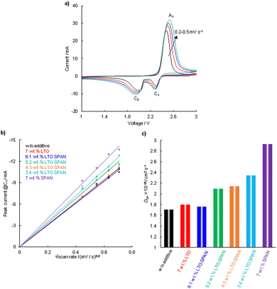 |
| | Fig. 4 (a) Cyclic voltammograms at different sweep rates from 0.2 to 0.5 mV s−1 for the Li–S cell with the 4:3 wt% LTO:SPAN cathode. (b) The plot of peak current for the C1 peak versus the square root of the sweep rate. (c) The Li+ ion diffusion coefficient estimated by the Randles–Sevcik equation in Li–S cells using cathodes with different additives. | |
3.4 Electrochemical performance in Li–S cell
The internal resistances of the Li–S cells with the cathodes containing the different additives were determined. Nyquist plots and an equivalent circuit model for the determination of a resistance component are shown in Fig. 5a. In the plots, the intersection of a semicircle with the real axis at a high frequency is assigned to the electrolyte resistance (RLiq.). A depressed semi-circle in middle and high-frequency regions corresponds to the sum of the charge transfer resistance in the cathode and anode (Rct).9 In this evaluation, it was assumed that Rct is dependent on the cathode because the evaluated Li–S cells were comprised of the same components except for the cathode. The 7 wt% SPAN cathode exhibited the highest charge transfer resistance of 5.13 Ω. In comparison, The 7 wt% LTO and 4:3 wt% LTO:SPAN cathodes showed lower charge transfer resistances than that of the 7 wt% SPAN cathode (7 wt% LTO 1.97 Ω, 4:3 wt% LTO:SPAN 2.48 Ω). These results are consistent with the EIS results of the symmetric cells, as shown in Fig. 3b.
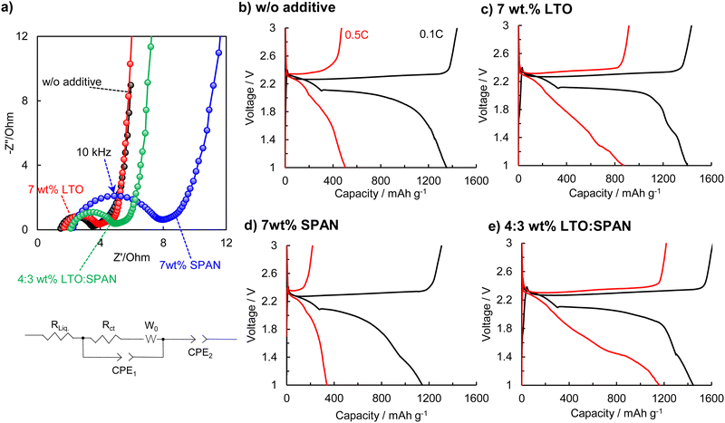 |
| | Fig. 5 (a) Nyquist plots of the Li–S cells using cathodes with different additives and an equivalent circuit model. The EIS was conducted in the frequency range of 3 MHz to 0.1 Hz with an amplitude of 10 mV at 60 °C. The initial charge–discharge curves of the Li–S cells using the cathodes with different additives. (b) w/o additive, (c) 7 wt% LTO, (d) 7 wt% SPAN, and (e) 4:3 wt% LTO:SPAN. The tests were conducted at 0.1C (0.84 mA cm−2) and 0.5C (4.2 mA cm−2). The mass of S per unit area was 5.0 mg cm−2 (8.4 mA h cm−2). | |
Fig. 5b–e demonstrates the charge–discharge curves. The rate performances were evaluated in the voltage range of 1.0–3.0 V. The w/o additive cathode exhibited the discharge capacity of 1351 mA h g−1 at 0.1C. On the other hand, the 7 wt% SPAN cathode delivered a low capacity of 1142 mA h g−1 at 0.1C, which is equal to only 68% of the sulfur utilization. The low utilization in the 7 wt% SPAN cathode results from a high charge transfer resistance due to the addition of SPAN, as shown in Fig. 5a.42 In comparison, the 7 wt% LTO and 4:3 wt% LTO:SPAN cathodes showed high discharge capacities of 1402 mA h g−1 and 1446 mA h g−1, corresponding to 84% and 86% of the sulfur utilization, respectively. More interestingly, we confirmed the superior rate performances in the dual-additives of LTO and SPAN when the C rate increased to 0.5C. The discharge capacity of the 7 wt% LTO cathode degrades to 870 mA h g−1 at 0.5C and exhibited a high polarization. In comparison, the 4:3 wt% LTO:SPAN cathode showed a much higher capacity of 1160 mA h g−1, maintaining 80% of the capacity at 0.1C.
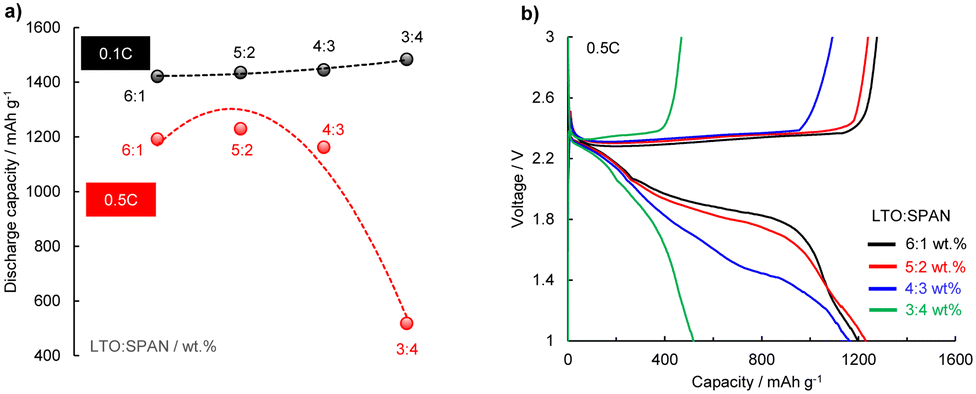
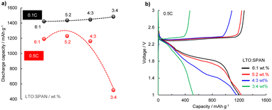
To further investigate the effect of the additives on the rate performance, the four cathodes with different ratios of LTO:SPAN (i.e., 6:1 wt% LTO:SPAN∼3:4 wt% LTO:SPAN) were compared. Fig. 6a and b show the discharge capacities (0.1C and 0.5C) in the different ratios and the voltage profiles at 0.5C. All the cathodes demonstrated almost the same discharge capacity of ca. 1450 mA h g−1 at 0.1C, as shown in Fig. 5a. However, the 3:4 wt% LTO:SPAN cathode exhibited large polarization, and the discharge capacity dropped to 870 mA h g−1 at 0.5C. In comparison, the 6:1 wt%, 5:2 wt%, and 4:3 wt% LTO:SPAN cathodes maintained more than 80% of the discharge capacities at 0.1C. Moreover, as shown in Fig. 6b, it can be seen that the polarization at 0.5C was increased with the increasing the SPAN additive ratio, suggesting that the increase of SPAN additive ratio leads to slow redox reaction in a cathode. In proof, the charge transfer resistance increased with increasing the SPAN additive ratio (Fig. S5 ESI,† 6:1 wt% LTO:SPAN/1.48 Ω, 5:2 wt% LTO:SPAN/1.09 Ω, and 4:3 wt% LTO:SPAN/2.48 Ω).
 |
| | Fig. 6 (a) Comparison of the discharge capacities at 0.1C (0.84 mA cm−2) and 0.5C (4.2 mA cm−2) and (b) the charge–discharge curves at 0.5C of the Li–S cells using the cathodes with different ratios of LTO and SPAN. The mass of S per unit area was 5.0 mg cm−2 (8.4 mA h cm−2). | |
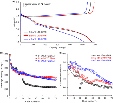
To reveal the effect of the LTO and SPAN additive ratio on the cycle stability, a long-term cycle performance test was conducted using the Li–S cells with the 6:1 wt%, 5:2 wt%, and 4:3 wt% LTO:SPAN cathodes. According to a previous report, better cycle stability was demonstrated by narrowing the cut-off voltage range in Li–S batteries.43 Thus, to obtain a more stable cycle performance, the cycle test was conducted in the voltage range of 1.5–2.7 V. The cathodes were prepared with a mass of S per unit area of 7.2 mg cm−2 (12.1 mA h cm−2). Fig. 7a shows the initial discharge–charge curves at 2.4 mA cm−2 which corresponds to 0.2C based on the weight of sulfur. The discharge capacities of the 6:1 wt% and 5:2 wt% cathodes were 1161 mA h g−1 and 1145 mA h g−1, respectively. It can be found that the 4:3 wt% cathode showed a relatively lower discharge capacity of 1026 mA h g−1 and a large polarization. These results were consistent with the result of Fig. 6b. Fig. 7b and c show the discharge capacity and coulombic efficiency during the cycle. It can be seen that the 6:1 wt% cathode exhibited obvious capacity fading and coulombic efficiency decreasing especially in the first 30 cycles. This suggests loss of S material and the redox shuttle behavior caused by the insufficient polysulfide adsorption. Compared with the 6:1 wt% cathode, the 5:2 wt%, and 4:3 wt% LTO:SPAN cathodes showed better cycle performance. The capacity decay per cycle during the cycle was 1.124%, 0.776%, and 0.784% for the 6:1 wt%, 5:2 wt%, and 4:3 wt% cathodes, respectively. Moreover, the 6:1 wt%, 5:2 wt%, and 4:3 wt% cathodes presented the average coulombic efficiency of 67.2%, 71.5%, and 78.2%, respectively. SPAN has a stronger adsorption capability compared to LTO in the adsorption test (Fig. 1 and Fig. S3, ESI†). It is suggested that the enhancement of the adsorption capability toward the polysulfide by increasing the SPAN additive ratio leads to the suppression of S material and the redox shuttle behavior, resulting in better cycle performance. Based on the results of the electrochemical tests, we noticed that the additive ratio of LTO and SPAN in a cathode is a key parameter for improving both the rate capability and the cycle stability.
 |
| | Fig. 7 Cycle performance of the Li–S cells using the cathodes containing LTO and SPAN. (a) Initial charge–discharge curves of the 6:1 wt%, 5:2 wt%, and 4:3 wt% LTO:SPAN cathodes. (b) Discharge capacity and (c) coulombic efficiency versus cycle number. The tests were conducted at 0.2C (2.4 mA cm−2) within the working potential between 1.5 V and 2.7 V. The mass of S per unit area was 7.2 mg cm−2 (12.1 mA h cm−2). | |
Conclusions
In summary, we studied the dual additive of LTO and SPAN in the cathode of the Li–S batteries. LTO provides not only an enhancement of the adsorption capability for lithium polysulfide but also a rapid charge transfer and fast Li+ ion diffusion in the cathode. However, only adding LTO is not enough to adsorb the polysulfide. Insufficient adsorption leads to a high charge transfer resistance due to reducing the intimate electrical contact between the polysulfide and the carbon matrix. Moreover, the poor polysulfide adsorption capability leads loss of S material and the redox shuttle behavior. SPAN with a much stronger interaction with the polysulfide helps to enhance the adsorption capability in the cathode, resulting in the improvement the cycle stability and the rate capability. The dual additive system synergistically affords the cathode with a strong lithium polysulfide adsorption capability and fast redox kinetics. However, the rate properties are reduced with an increase in the SPAN additive ratio due to increasing the charge transfer resistance. In contrast, it should be noted that the excess reduction of the SPAN additive ratio leads to insufficient adsorption toward the polysulfide, resulting in low cycle performance. It is suggested that the additive ratio of LTO and SPAN in a cathode is a key parameter for improving both the rate capability and the cycle stability.
Conflicts of interest
There are no conflicts to declare.
Acknowledgements
Sulfurized polyacrylonitrile (SPAN) was provided by ADEKA Co., Ltd. This work was supported by The Furukawa Battery Co., Ltd.
References
- P. G. Bruce, S. A. Freunberger, L. J. Hardwick and J.-M. Tarascon, Nat. Mater., 2011, 11(1), 19 CrossRef PubMed.
- W. Ren, W. Ma, S. Zhang and B. Tang, Energy Storage Mater., 2019, 23, 707 CrossRef.
- G. Ye, M. Zhao, L.-P. Hou, W.-J. Chen, X.-Q. Zhang, B.-Q. Li and J.-Q. Huang, J. Energy Chem., 2022, 66, 24 CrossRef CAS.
- Z. Yuan, H.-J. Peng, T.-Z. Hou, J.-Q. Huang, C.-M. Chen, D.-W. Wang, X.-B. Cheng, F. Wei and Q. Zhang, Nano Lett., 2016, 16, 519 CrossRef CAS PubMed.
- Y. Liu, Y. Elias, J. Meng, D. Aurbach, R. Zou, D. Xia and Q. Pang, Joule, 2021, 5, 2323 CrossRef CAS.
- S. S. Zhang, J. Power Sources, 2016, 322, 99 CrossRef CAS.
- W. Bao, D. Su, W. Zhang, X. Guo and G. Wang, Adv. Funct. Mater., 2016, 26, 8746 CrossRef CAS.
- X. Liang, C. Y. Kwok, F. L-Marzano, Q. Pang, M. Cuisinier, H. Huang, C. J. Hart, D. Houtarde, K. Kaup, H. Sommer, T. Brezesinski, J. Janek and L. F. Nazar, Adv. Energy Mater., 2016, 6, 1501636 CrossRef.
- J. Xu, W. Zhabg, H. Fan, F. Cheng, D. Su and G. Wang, Nano Energy, 2018, 51, 73 CrossRef CAS.
- K. Shi, C. Lai, X. Liu, Y. Wei, W. Lv, J. Wang, J. Li, C. Yan, B. Li, Q.-H. Yang, F. Kang and Y.-B. He, Energy Storage Mater., 2019, 17, 111 CrossRef.
- R. Wang, K. Wang, H. Tao, W. Zhao, M. Jiang, J. Yan and K. Jiang, J. Mater. Chem. A, 2020, 8, 11224 RSC.
- B. Wang, F. Jin, Y. Xie, H. Luo, F. Wang, T. Ruan, D. Wang, Y. Zhou and S. Dou, Energy Storage Mater., 2020, 26, 433 CrossRef.
- H. Gao, S. Ning, J. Zou, S. Men, Y. Zhou, X. Wang and X. Kang, J. Energy Chem., 2020, 48, 208 CrossRef.
- J. Ming, M. Li, P. Kumar and L.-J. Li, ACS Nano, 2016, 10, 6037 CrossRef CAS PubMed.
- Y. Zhao, M. Liu, W. Lv, Y.-B. He, C. Wang, Q. Yun, B. Li, F. Kang and Q.-H. Yang, Nano Energy, 2016, 30, 1 CrossRef CAS.
- P.-P. R. M. L. Harks, T. W. Verhallen, C. George, J. K. v d Biesen, Q. Liu, M. Wagemaker and F. M. Mulder., J. Am. Chem. Soc., 2019, 141, 14280 CrossRef CAS PubMed.
- W. Yuan, Z. Qiu, C. Wang, Y. Yuan, Y. Yang, X. Zhang, Y. Ye and Y. Tang, Chem. Eng. J., 2020, 381, 122648 CrossRef CAS.
- T. Zeng, X. Hu, P. Ji, B. Shang, Q. Peng, Y. Zhang and R. Song, J. Power Sources, 2017, 359, 250 CrossRef CAS.
- Y. Zhang, X. Zhang, S. R. P. Silva, B. Ding and P. Zhang, Adv. Sci., 2022, 9, 2103879 CrossRef CAS PubMed.
- K. Zou, W. Jing, X. Dai, X. Chen, M. Shi, Z. Yao, T. Zhu, J. Sun, Y. Chen, Y. Liu and Y. Liu, Small, 2022, 18, 2107380 CrossRef CAS PubMed.
- S.-H. Moon, J.-H. Shin, J.-H. Kim, J.-S. Jang, S.-B. Kim, Y.-Y. Park, S.-N. Lee and K.-W. Park, Mater. Chem. Phys., 2022, 287, 126267 CrossRef CAS.
- Q. Li, Z. Ma, J. Zhao, K. Shen, T. Shi, Y. Xie, Y. Fan, X. Qin and G. Shao, J. Power Sources, 2022, 521, 230929 CrossRef CAS.
- C.-J. Huang, J.-H. Cheng, W.-N. Su, P. P-Azar, L.-Y. Kuo, M.-C. Tsai, M.-H. Lin, S. P. Jand, T.-S. Chan, N.-L. Wu, P. Kaghazchi, H. Dai, P. M. Bieker and B.-J. Hwang, J. Power Sources, 2021, 492, 229508 CrossRef CAS.
- Q. Li, M. Liu, X. Qin, J. Wu, W. Han, G. Liang, D. Zhou, Y.-B. He, B. Li and F. Kang, J. Mater. Chem. A, 2016, 4, 12973 RSC.
- Y. Deng, H. Xu, Z. Bai, B. Hung, J. Su and G. Chen, J. Power Sources, 2015, 300, 386 CrossRef CAS.
- H. Yuan, W. Zhang, J.-g Wang, G. Zhou, Z. Zhuang, J. Luo, H. Huang, Y. Gan, C. Liang, Y. Xia, J. Zhang and X. Tao, Energy Storage Mater., 2018, 10, 1 CrossRef.
- R. D. Rauh, F. S. Shuker, J. M. Marston and S. B. Brummer, J. Inorg. Nucl. Chem., 1977, 39, 1761 CrossRef CAS.
- X. Ji, K. T. Lee and L. F. Nazar, Nat. Mater., 2009, 8(6), 500 CrossRef CAS PubMed.
- H. Munakata, D. Yamamoto and K. Kanamura, J. Power Sources, 2008, 178, 596 CrossRef CAS.
- Y. Maeyoshi, D. Ding, M. Kubota, H. Ueda, K. Abe, K. Kanamura and H. Abe, ACS Appl. Mater. Interfaces, 2019, 11(29), 25833 CrossRef CAS PubMed.
- X. Tao, J. Wang, Z. Ying, Q. Cai, G. Zheng, Y. Gan, H. Huang, Y. Xia, C. Liang, W. Zhang and Y. Cui, Nano Lett., 2014, 14(9), 528 CrossRef.
- C. J. Huang, K. Y. Lin, Y. C. Hsieh, W. N. Su, C. H. Wang, G. Brunklaus, M. Winter, J. C. Jiang and B. J. Hwang, ACS Appl. Mater. Interfaces, 2021, 13(12), 14230 CrossRef CAS.
- X. Huang, Z. Wang, R. Knibbe, B. Luo, S. A. Ahad, D. Sun and L. Wang, Energy Technol., 2019, 7, 1801001 Search PubMed.
- H. Ye, J. Sun, S. Zhang, T. Zhang, Y. Zhao, C. Song, Q. Yao and J. Y. Lee, Chem. Eng. J., 2021, 410, 128284 CrossRef CAS.
- J. Xu, W. Zhang, H. Fan, F. Cheng, D. Su and G. Wang, Nano Energy, 2018, 51, 73 CrossRef CAS.
- C. X. Zhao, W. J. Chen, M. Zhao, Y. W. Song, J. N. Liu, B. Q. Li, T. Yuan, C. M. Chen, Q. Zhang and J. Q. Huang, EcoMat, 2021, 3, 12066 CrossRef.
- N. Ding, J. Xu, Y. X. Yao, G. Wegner, X. Fang, C. H. Chen and I. Lieberwirth, Solid State Ionics, 2009, 180, 222 CrossRef CAS.
- C. A. Zachart, D. Wawerzyniakowski, J. T. Postlewaite and Y. Ma, J. Phys. Chem. C, 2018, 122, 8769 CrossRef.
- J. Hu, Y. Jiang, S. Cui, Y. Duan, T. Liu, H. Guo, L. Lin, Y. Lin, J. Zheng, K. Amine and F. Pan, Adv. Energy Mater., 2016, 6, 1600856 CrossRef.
- W. Yan, K.-Y. Yan, G.-C. Kuang and Z. Jin, Chem. Eng. J., 2021, 423, 130246 CrossRef.
- X. Tao, J. Wang, C. Liu, H. Wang, H. Yao, G. Zheng, Z. W. Seh, Q. Cai, W. Li, G. Zhou, C. Zu and Y. Cui, Nat. Commun., 2016, 7, 11203 CrossRef CAS.
- Z. Chang, H. Dou, B. Ding, J. Wang, Y. Wang, G. Xu and C. Li, New J. Chem., 2016, 40, 7680 CAS.
- J. Liao and Z. Ye, Batteries, 2018, 4, 22 CrossRef.
Footnote |
| † Electronic supplementary information (ESI) available: TGA plots of S/C Novel; Raman spectra with the solutions; atomic ratios of the SPAN surface obtained by XPS before/after the polysulfide adsorption test; cyclic voltammogram in in the different cathode; Nyquist plots of Li–S cells using different weight ratios of LTO and SPAN and an equivalent circuit model; charge–discharge curves in cycle performance. See DOI: https://doi.org/10.1039/d2cp04282g |
|
| This journal is © the Owner Societies 2023 |
Click here to see how this site uses Cookies. View our privacy policy here. 
 *a,
Jungo
Wakasugi
a,
Masaaki
Kubota
a,
Kiyoshi
Kanamura
ab and
Hidetoshi
Abe
*ac
*a,
Jungo
Wakasugi
a,
Masaaki
Kubota
a,
Kiyoshi
Kanamura
ab and
Hidetoshi
Abe
*ac