
Molecular dynamics and kinetics of isothermal cold crystallization with tunable dimensionality in a molecular glass former, 5′-(2,3-difluorophenyl)-2′-ethoxy-4-pentyloxy-2,3-difluorotolane†
Tomasz
Rozwadowski
 *ab,
Hiroshi
Noda
a,
Łukasz
Kolek
c,
Mizuki
Ito
a,
Yasuhisa
Yamamura
a,
Hideki
Saitoh
d and
Kazuya
Saito
a
*ab,
Hiroshi
Noda
a,
Łukasz
Kolek
c,
Mizuki
Ito
a,
Yasuhisa
Yamamura
a,
Hideki
Saitoh
d and
Kazuya
Saito
a
aDepartment of Chemistry, Faculty of Pure and Applied Sciences, University of Tsukuba, Tsukuba, Ibaraki 305-8571, Japan. E-mail: tomasz.rozwadowski@prz.edu.pl
bDepartment of Chemical and Process Engineering, Faculty of Chemistry, Rzeszow University of Technology, 35-959 Rzeszow, Poland
cDepartment of Material Science, Faculty of Mechanical Engineering and Aeronautics, Rzeszow University of Technology, 35-959 Rzeszow, Poland
dDepartment of Chemistry, Graduate School of Science and Engineering, Saitama University, Saitama 338-8570, Japan
First published on 1st December 2022
Abstract
This paper characterizes the molecular mobility that triggers the cold crystallization abilities in 5′-(2,3-difluorophenyl)-2′-ethoxy-4-pentyloxy-2,3-difluorotolane (short name DFP25DFT) material by broadband dielectric spectroscopy (BDS). We analyze the properties of identified molecular motions by referring to the Vogel–Fulcher–Tammann (VFT) model for the structural α-process associated with molecular rotation in isotropic liquid and the Eyring and Starkweather approach for the thermally activated processes, β-process related to intramolecular movement in liquid and glassy state and emerging during cold crystallization α′-process ascribed to confined movements of molecules located adjacent to crystalline surfaces. To characterize the material, we employ single-crystal X-ray diffraction, differential scanning calorimetry (DSC), adiabatic calorimetry, and polarizing optical microscopy (POM), while we utilize molecular mechanics simulations (MM2) to explore molecular flexibility. Our study focuses on inter- and intramolecular interactions that determine the cold-crystallization tendency. We demonstrate that the solidification path is controlled by the fragility of the system, the dipole–dipole attraction, and the intramolecular dynamics. The study of cold crystallization kinetics under isothermal conditions reveals the complexity of the process: the formation of two crystalline phases, Cr2 and Cr3, proceeding in different modes. This feature discloses the possibility of switching the crystal growth between three- and two-dimensional in the cold-crystallization process driven by different mechanisms.
1. Introduction
A comprehensive description of the molecular processes controlling glass formation and crystallization is a vital challenge in present-day science and technology. The design of materials requires detailed studies on solidification processes since the molecular arrangement and dimensionality of the structure govern most of the essential physical properties. The molecular disorder in the amorphous state and the order in the crystal, on a long-range scale, affect the key features of the material.1–3 Further, even if the crystal structure remains the same, the molecular arrangement with different spatial dimensions can dramatically change the physical properties. Hence, the switching ability between three-(3D) and two-dimensional (2D) crystal growth offers a wealth of new phenomena usually abundant in 2D systems, which opens ways for novel applications.4–9 Some recent advances in crystallization studies come from kinetics examinations of the process and providing mechanistic insights, dimensionality analysis of structure growth, and support for developing procedures of industrial crystallization of various types of matter.10–18Upon cooling, a liquid phase undergoes a steady supercooling and finally vitrifies or forms a crystalline phase. From a fundamental point of view, the actual path is determined by the nucleation rates, growth of formed nuclei, and the diffusion of molecules (molecular mobility). In principle, the thermodynamic mechanism of both nucleation and crystal growth exposes its dominance over molecular mobility at higher temperature ranges. The ability of the glass formation is an effect of the separation of the curves of nucleation and growth rates, whereas the overlapping promotes crystallization in cooling. For glass formers, the cold-crystallization process is expected on reheating of the amorphous phase.19–22
Attempts at a universal description of cold crystallization indicate that its occurrence is related to the chemical structure of the molecules in the system. Cold crystallization is often detected in molecular structures that are unsymmetrical and/or exhibit high internal mobility (flexibility), e.g., rotation of phenyl groups, which provides a significant entropy change in the transition from the isotropic liquid into the solid phase and results in an increase of activation energy of crystallization by the intramolecular energy barrier.23–26 It favors the formation of an amorphous state and brings the crystalline phase growth to the subsequent heating process. Namely, cold crystallization is commonly found in polymeric materials due to the flexibility of macromolecular chains with various backbone conformations.27,28 In contrast, the process is less common in systems of small molecules. However, some small molecules possess unsymmetrical substituents and suitable intramolecular dynamics features that promote crystallization during heating.24,29,30 Cold crystallization is also found in various types of partially ordered mesophases.31–35 Macroscopically, these systems often offer peculiar crystal morphologies and appear to be of particular interest.32,36,37 Recently, the cold crystallization of small molecules has attracted attention due to its potential in some branches of industry. The related studies aim to address the arising problems in sustainability and energetics and develop new functional and pharmaceutical materials.30,38–41
The molecular interactions dominate the physical and dynamical properties of the system and, as a result, influence the progress of the crystallization process. The overall molecular interaction potential can be considered the sum of a short-range repulsion and a long-range attraction potential from the London dispersion force. The attraction part of the overall intermolecular potential is also contributed by the dipole–dipole interaction proven as one of the essential factors determining suppression of crystallization during cooling in various types of molecular glass formers.42–44
In the present study, we examine the properties of the molecular system that determine the ability for cold crystallization in 5′-(2,3-difluorophenyl)-2′-ethoxy-4-pentyloxy-2,3-difluorotolane (hereafter, DFP25DFT). The molecular structure resembles o-terphenyl (OTP), the model glass-forming liquid, which is the subject of longstanding investigations.45–51 OTP is broadly applied as a raw material for organic synthesis and pharmaceutical intermediate, and its derivatives are used in organic light-emitting diodes (OLEDs).52–54 The chemically more complex molecule of DFP25DFT possesses polar groups and alkyl chains in alkoxy moieties that generally act as a trigger of crystallization.25,39,55,56
Fluorination of the molecule increases the dynamic viscosity and density of the material and the intermolecular interactions, fostering crystal formation.57–60 Consequently, the substitution pattern in DFP25DFT provides a difference from OTP that brings the capability for complex cold crystallization. The molecular design of DFP25DFT thus creates an opportunity to detect and describe additional molecular processes and interactions that control glass formation and crystal growth through cold crystallization in the system of low-weight molecules. Broadband dielectric spectroscopy (BDS) offers detailed insights into the molecular mobility and solidification processes together with adiabatic calorimetry, differential scanning calorimetry (DSC), X-ray crystallography, and polarizing optical microscopy (POM). Our study focuses on the processes involved in the inter- and intramolecular levels and refers to the dipole–dipole interaction that affects the structural relaxation and the internal mobility of the molecule as the secondary dynamics. We identify the origin of intramolecular movement that controls crystallization behavior while utilizing a simple computational analysis (MM2 method). The complex cold crystallization is analyzed through kinetics studies of the processes under isothermal conditions. We investigate the mechanisms driving molecular aggregation in two- or three-dimension during the formation of the crystal phases.
2. Results and discussion
2.1 Phase relation
Before detailed experiments for molecular dynamics and crystallization of DFP25DFT, we performed fundamental characterization of the compound, including the structure determination of a single-crystal grown from an organic solvent by X-ray crystallography. The crystallography revealed an issue for an existing paper,61 but it is not a subject of the present paper.The investigated material is a polar glass former whose optimized molecular structure is shown in Fig. 1. The dielectric response of the compound in various physical states originates from the dynamics of the electric dipole moment with a total value of μ = 4.04 D.
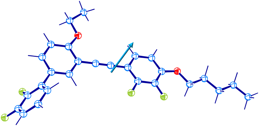 | ||
| Fig. 1 Molecular structure of DFP25DFT optimized by the PM6 method. Hydrogen atoms are omitted for clarity. Blue, green, and red denote carbon, fluorine, and oxygen atoms. The arrow shows the vector of the total electric dipole moment. | ||
Differential scanning calorimetry yielded complex results depending on cooling/heating rates and thermal history. The phase behavior related to this study is rationalized by assuming three crystalline forms of DFP25DFT. Fig. 2 is a schematic G–T (Gibbs energy vs. temperature) diagram summarizing their thermodynamic relation. The as-supplied specimen is in crystal Cr1 form, which is the most stable thermodynamically. The Cr1 phase melts around 340 K to the isotropic liquid. The melting behavior is consistent with the literature61 that claimed a different molecular structure based on spectroscopic characterization during the chemical synthesis. The liquid vitrifies upon cooling, yielding the glass, regardless of the cooling rate (down to ca. −0.5 K min−1). The glass softens around 250 K into the supercooled (metastable) liquid on heating. Nothing happens up to temperatures above the melting point when the heating is fast, such as 10 K min−1. However, a crystallization into not Cr1 but metastable Cr2 form occurs above 290 K if the heating rate is moderate (less than ca. 5 K min−1). The Cr2 melts at 324 K on heating. Cold crystallization at higher temperatures than 324 K yielded crystal Cr3, which melts at 335 K. Representative charts are in the ESI.† Note that any thermal treatments could not yield the most stable Cr1 form.
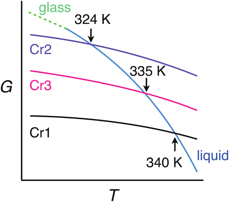 | ||
| Fig. 2 Gibbs energy vs. temperature (G–T) diagram of DFP25DFT deduced based on the DSC results. | ||
We measured heat capacities using adiabatic calorimetry to establish thermodynamic functions for stable states. Fig. 3(a) shows the experimental molar heat capacities measured during the heating of crystalline and amorphous solids from 6 K. In the first run, the sample in the initial crystalline phase Cr1, presumably recrystallized from solvent by the supplier, melts to the liquid phase at 340.0 K. Subsequent cooling of the liquid results in the formation of an amorphous solid, for which the heat capacities are collected in the second measurement run. The anomaly around 250 K exhibits behavior typical for glass transition, which accompanies a significant jump in heat capacity and an enthalpy relaxation in temperature drift during the equilibration periods (Fig. 3(b)). The glass transition temperature was determined as 249 K, at which the temperature drift changes its sign from exothermic to endothermic. On further heating, the cold crystallization to phase Cr2 is found around 296 K. The third run conducted after the complete cold crystallization revealed a phase transition between crystalline phases at 83.7 K, as seen in the inset of Fig. 3a. The values of the heat capacities of Cr2 far from the phase transition are undoubtedly distinguishable from those of the phase Cr1. The Cr1 is the most stable thermodynamically. The smallest heat capacity of Cr1 among the three crystalline phases at most temperatures is consistent with this finding. The melting of crystal Cr2 at 324 K immediately triggered the stabilization to Cr1 in adiabatic experiments, differently from the DSC cases due to the short times for experiments in the latter. Thus, Cr3 is not stable enough to be subject to adiabatic measurements. Both calorimetric techniques yield thermodynamic quantities related to (phase) transitions tabulated in Table 1. Standard thermodynamic quantities of the stable phases are in the ESI.† The configurational (i.e., the residual) entropy of the glass was estimated as 32 J K−1 mol−1 at 0 K while assuming the third law for Cr1.
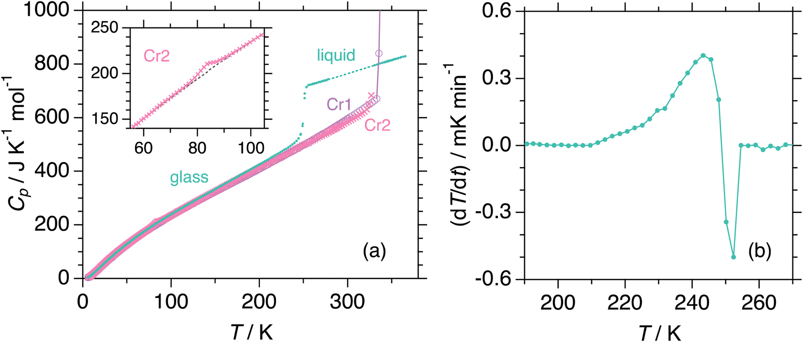 | ||
| Fig. 3 (a) Experimental molar heat capacities of DFP25DFT obtained in the runs from the crystal Cr1 (open circle), crystal Cr2 (cross), and glass (filled circle). The inset shows heat capacities of Cr2 exhibiting a phase transition together with the assumed baseline to separate the anomaly. (b) Temperature drifts corrected for the normal drift during the equilibration period in the glass transition region. | ||
| Transition | T trs (K) | ΔtrsH (kJ mol−1) | ΔtrsS (J K−1 mol−1) | Method |
|---|---|---|---|---|
| Glass transition | ≈249 | (ΔCp = 197 J K−1 mol−1) | Adiabatic | |
| Melting of Cr1 | 340.00 ± 0.05 | 37.12 ± 0.01 | 109.2 ± 0.1 | Adiabatic |
| Melting of Cr2 | 324 ± 1 | 37.2 ± 0.6 | 115 ± 2 | DSC |
| Melting of Cr3 | 335 ± 1 | 38.2 ± 1.0 | 115 ± 3 | DSC |
| Cr2”–Cr2 transition | 83.7 ± 0.6 | (89.4 ± 0.4) × 10−3 | 1.10 ± 0.01 | Adiabatic |
We confirmed the phase behavior by analyzing the dielectric response of the system and microscopic textures after melting the initial phase Cr1 in the first heating. These examinations cover the temperature range of molecular dynamics and crystallization kinetics studies. Fig. 4 displays the temperature evolution of the dielectric dispersion ε′ (a) and microscopic images by POM (b) in cooling and heating. The solidification processes are reflected in the decrease in dielectric permittivity due to the slowing-down of the main molecular motion upon immobilization of molecules in the crystal lattice, as discussed in detail in the next section. On cooling, the liquid loses its fluidity at the glass transition, and the POM observations reveal a surviving lack of long-range molecular order, displayed by no change in the light polarization in the material, as expected for the disordered isotropic state. The characteristic cracks due to the volume change are visible in the glassy state. Then on reheating, glass softening is followed by two cold-crystallization processes of the Cr2 and Cr3 phases. Note that melting of the initial phase Cr1, which is the most stable thermodynamically, demonstrates seeming irreversibility, and the phase Cr1 is not observed by any thermal treatments in the time range of the present experiments.
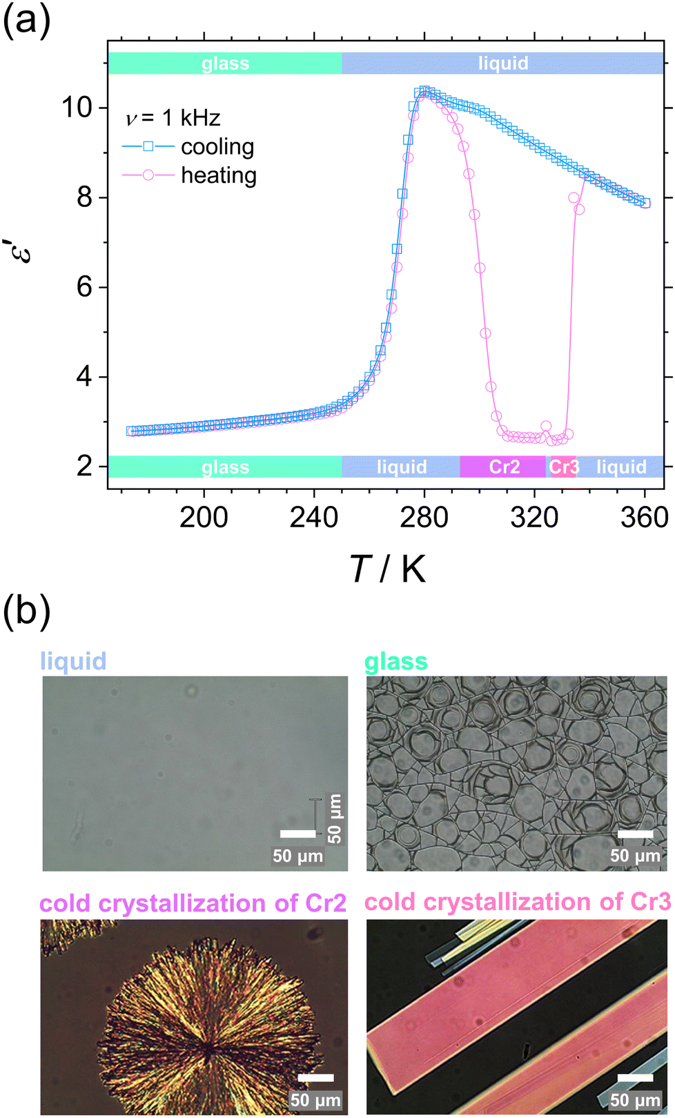 | ||
| Fig. 4 Phase transitions in DFP25DFT. (a) Temperature dependence of dielectric dispersion ε′ at a frequency of 1 kHz for cooling and heating. The temperature range of phases at cooling and heating are shown on the upper and lower scale, respectively. (b) POM micrographs of liquid at 293 K, glassy state at 123 K on cooling, and cold crystallization of Cr2 phase at 307 K and Cr3 phase at 330 K on heating. Scale bars, 50 μm. | ||
2.2 Molecular dynamics
To describe the mobility and interaction behavior of the molecules involved in the solidification processes, we examine the molecular dynamics in DFP25DFT. First, we analyze the complex dielectric spectra collected in cooling and subsequent heating by employing the Havriliak–Negami (HN) equation:62–64 | (1) |
 and
and  , ω = 2πν is the angular frequency, aHN and bHN are shape parameters related to the symmetric and asymmetric broadening of the relaxation peak (aHN = bHN = 1 for the Debye relaxation, aHN = 1 for the Cole–Davidson relaxation, bHN = 1 for the Cole–Cole relaxation). The last term accounts for ohmic conduction at low-frequency limits: σ0 is the direct current (DC) conductivity, ε0 is vacuum permittivity, and c is a fitting parameter. The dielectric strength Δε is proportional to both the mean-square dipole moment (μ2/kT; k, the Boltzmann constant) and the density of the reorienting dipoles and therefore provides a measure of the number of molecules involved in the relaxation process. We characterize the molecular dynamics and kinetics of crystallization processes based on this relation.
Fig. 5 shows dielectric dispersion ε′(ν) and absorption ε′′(ν) spectra in cooling and heating. In the liquid phase (squares), we can recognize the main α-relaxation and secondary β-relaxation, and after the glass transition on cooling (circles), the latter remains. The α-relaxation is ascribed to the rotational motion of the whole molecule, while the β-relaxation, characterized by absorption peaks of lower intensity, comes from the intramolecular origin, as discussed later. During the cold crystallization of both phases Cr2 (lower half-filled diamonds) and Cr3 (upper half-filled diamonds), in the advanced progress of the process observed as decreased α-relaxation peak, the additional α′-process emerges in the lower frequency range and then ceases at the end of crystal growth. This process can be ascribed to the slow collective motion of spatially constrained fractions of aggregating molecules near crystalline surfaces.
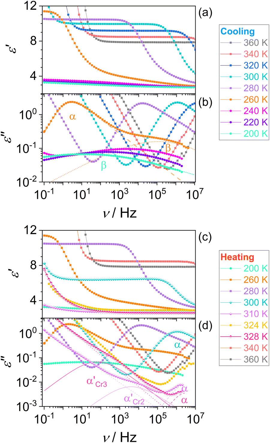 | ||
| Fig. 5 Dielectric spectra of DFP25DFT on cooling [(a) and (b)] and heating [(c) and (d)]. The deconvolution of absorption spectra (ε”) by the Havriliak–Negami equation is shown for liquid (260 K) and glass (200 K) in (b) and during cold crystallization of Cr2 (310 K) and Cr3 (328 K) in (d). | ||
Fig. 6 depicts the temperature dependence of the relaxation times of individual processes determined by utilizing eqn (1) for dielectric loss spectra ε′′(ν). The processes β and α′ show Arrhenius behavior, whereas the α-relaxation times rapidly increase by approaching the glass transition and exhibit dependence described by the empirical Vogel–Fulcher–Tammann (VFT) equation:65–67
 | (2) |
 | ||
| Fig. 6 Relaxation map for cooling and heating of DFP25DFT, the blue line shows a fit of the Vogel–Fulcher–Tammann equation to the data on cooling. | ||
Based on the temperature dependences of the relaxation times for each process depicted in Fig. 6, we determine the quantities that describe the features of molecular mobility. Table 2 collects the obtained results.
 ) and Cr3 (
 ). Parameters aHN, bHN, and Δε of the Havriliak–Negami model determined at temperature T
| Process | VFT | ||||||||
|---|---|---|---|---|---|---|---|---|---|
| D | T 0 (K) | τ 0 (s) | T g (K) | m | T (K) | a HN | b HN | Δε | |
| α | 5.3 ± 0.3 | 216 ± 1 | (4 ± 0.7) × 10−13 | 250.5 ± 2.0 | 104.8 ± 5.9 | 254 | 0.94 ± 0.02 | 0.48 ± 0.02 | 7.68 ± 0.38 |
| Arrhenius | |||||||
|---|---|---|---|---|---|---|---|
| E a (kJ mol−1) | ΔH0 (kJ mol−1) | ΔS# (J mol−1 K−1) | T (K) | a HN | b HN | Δε | |
| β | 77.1 ± 1.6 | 44.7 ± 0.8 | 169.5 ± 9.6 | 200 | 0.20 ± 0.04 | 0.94 ± 0.10 | 0.87 ± 0.04 |

|
76.6 ± 9.3 | 57.9 ± 7.2 | 76.2 ± 9.2 | 310 | 0.60 ± 0.02 | 0.90 ± 0.10 | 0.03 ± 0.01 |
|
102.2 ± 14.6 | 72.5 ± 10.6 | 97.9 ± 13.7 | 328 | 0.60 ± 0.05 | 1.00 ± 0.10 | 0.27 ± 0.01 |
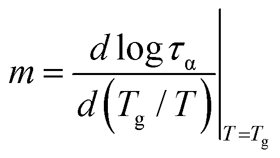
To classify a glass-forming system in terms of molecular dynamics evolution, we employ the so-called dynamic fragility index m that describes the sensitiveness of the structural α-relaxation process to temperature changes at the glass transition:68
 | (3) |
Since the temperature dependence of α-relaxation time, τα(T), significantly deviates from the Arrhenius behavior, the fragility parameter m for DFP25DFT is expectantly high. Therefore, according to the Angell classification scheme, the substance is classified into fragile systems with m > 100. Fragile systems are regarded as structurally less stable than strong ones, arising from considerable changes in molecular mobility in the vicinity of Tg. Namely, fragile glass formers exhibit weaker restrictions for molecular rearrangements fostering a subsequent crystallization process.69 A high tendency for cold crystallization exhibited by fragile organic glass formers21,35,70,71 confirms this hypothesis.
The analysis of the molecular interaction in the vicinity of the glass transition reveals additional insight into the molecular dynamics that determine the subsequent cold-crystallization processes. In general, it has been demonstrated that the dielectric strength Δε is correlated with departure from the Debye process of the α-relaxation at glass transition,42 quantified by the Kohlrausch–Williams–Watts stretching parameter βKWW (0 < βKWW ≤ 1; βKWW = 1 for the Debye relaxation):72
 | (4) |
This correlation is rationalized in terms of the dipole–dipole interaction in the molecular system. The averaged interaction energy of two identical freely rotating dipoles with electric dipole moment μ at distance r between them is given by44
 | (5) |
The dipole–dipole interaction contributes to the total attractive part of the intermolecular potential and makes it more harmonic. Since the anharmonicity broadens the dispersion of the α-relaxation times, the enhancement of the dipole–dipole interaction makes this dispersion weaker. Therefore, this leads to a narrower α-relaxation peak with higher parameter βKWW, which is correlated with increasing |Vdd|. Besides, the Δε is proportional to μ2/kT. Thus, the following relation stands:
| |Vdd| ∝ kT[Δε(T)]2 | (6) |
Namely, kTg[Δε(Tg)]2 against βKWW(Tg) shows a linearly increasing relationship for polar glass formers.42,43 In the present case, kTg[Δε(Tg)]2 is 2 × 10⁻¹⁹ J, and βKWW(Tg) is 0.52, which falls well within the range of the reported trend. Furthermore, it has been suggested that the physical stability decreases with a more significant distribution of the structural relaxation times, i.e., with decreasing the parameter βKWW.73 Thus, it can be concluded that weak dipole–dipole attraction essentially leads to an enhanced tendency to recrystallization.
To complete the description of molecular behavior, we analyze the Arrhenius processes, secondary β-relaxation, and collective processes that arise during cold crystallization (α′), through the activation energy. An insight is given by the method proposed by Eyring74 and revised by Starkweather.75 On the basis of their approach, we determine activation enthalpy and entropy, which are measures of dynamical cooperativity. Namely, the theoretical activation enthalpy ΔH0 associated with zero activation entropy is given by the following equation:
 | (7) |
 | (8) |
The energy and enthalpy of activation depend on the local molecular environment and reflect molecular freedom of rotation, while the activation entropy indicates the change of the system order associated with individual relaxation. The activation parameters, Ea, ΔH0, of α′-process involved in the crystallization of the Cr2 and Cr3 phases display noticeably higher values for the latter, a much slower process, reflecting a higher hindrance in the mobility of molecules confined by the growing crystallites. Positive values of ΔS# for all relaxation indicate their cooperative dynamics. The activation enthalpy is lower for β-relaxation than for α′-processes, while the activation entropy shows the reverse relation. This relation suggests that the β-relaxation originates in the movement of only a part(s) of the molecule while significantly influencing the system order.
To identify the internal motion involved in the β-relaxation, we utilize a simple computational analysis of an isolated molecule by the MM2 method. Fig. 7 displays the calculated relative energy for a torsion (dihedral) angle of the rotatable bonds in the molecule. As presented in (a), the change in conformational energy of the molecule associated with the rotation of the fluorinated side ring (sketched by the arrow in (b)) corresponds to the activation energy of the β-relaxation process (Table 2). Consequently, this intramolecular motion contributes with its energy barrier to the crystallization activation energy and affects the system's fragility. Thus, this molecular feature is essential in promoting the solidification path with crystal growth in reheating through the cold-crystallization process.
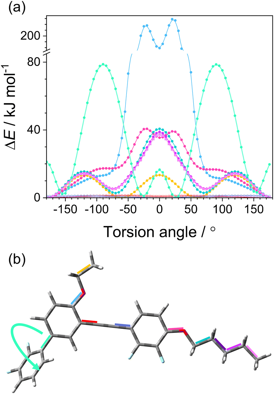 | ||
| Fig. 7 (a) Relative molecular energy ΔE for a torsion angle of individual rotatable bonds marked with a corresponding color in the DFP25DFT molecule in (b) (see for an enlargement plot in ESI†). (b) Molecular structure with investigated bonds denoted with colors; movement related to β-process is shown by the arrow. | ||
2.3 Isothermal cold crystallization kinetics of Cr2 and Cr3
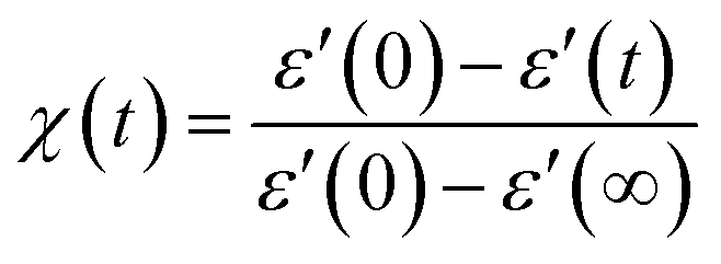
This section examines the link of molecular mobility properties with the isothermal crystallization kinetics of the two crystalline phases, Cr2 and Cr3. For this purpose, we analyze the real-time evolution of the dielectric dispersion spectra ε′(ν) at temperatures of 298 K, 317 K, 330 K and 334 K, located in a region of crystallization of Cr2 (the former two) and Cr3 (the rest), respectively (see the phase temperature range in Fig. 2).Crystallization is associated with the hindrance of the dynamics of polar molecules, observed as the reduction of electric permittivity. Under this assumption, the progress of immobilization of molecules in the crystal lattice is monitored by the decrease in the real part ε′ of dielectric spectra, as depicted in Fig. 8. The crystallinity degree χ as the crystal volume fraction is estimated from dielectric dispersion ε′ as follows:
 | (9) |
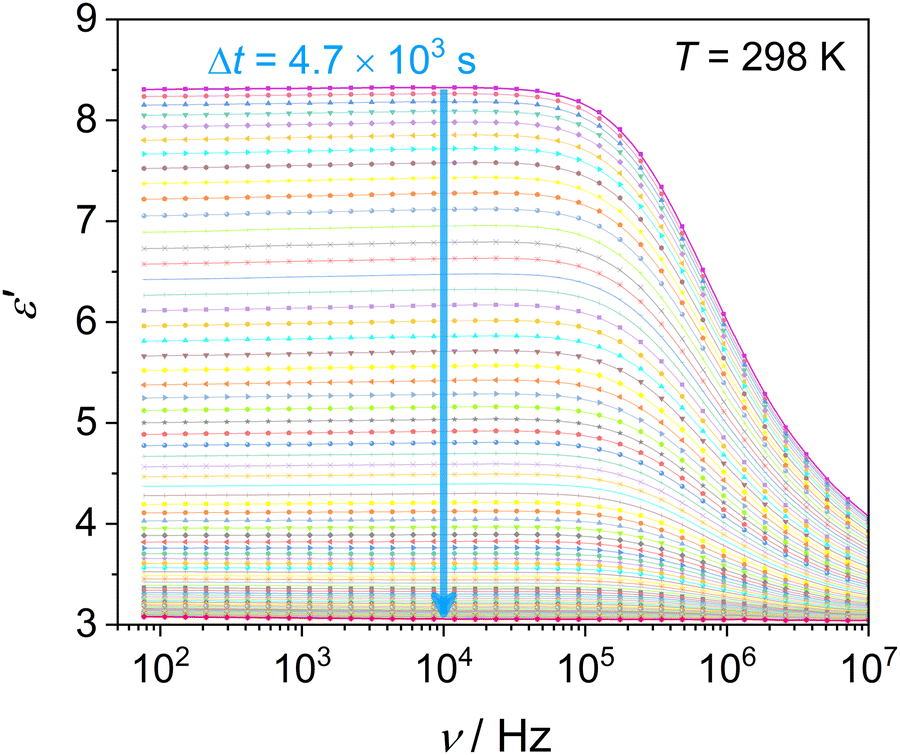 | ||
| Fig. 8 Time evolution of the real part of dielectric permittivity spectra ε′(ν) of DFP25DFT during the isothermal crystallization of Cr2 at T = 298 K. The arrow indicates the crystallization progress. | ||
To investigate crystal growth kinetics and quantitatively capture the differences between the crystallization of Cr2 and Cr3, we employ a commonly used Avrami model:76,77
| χ(t) = 1 − exp[−K(t − t0)n] | (10) |
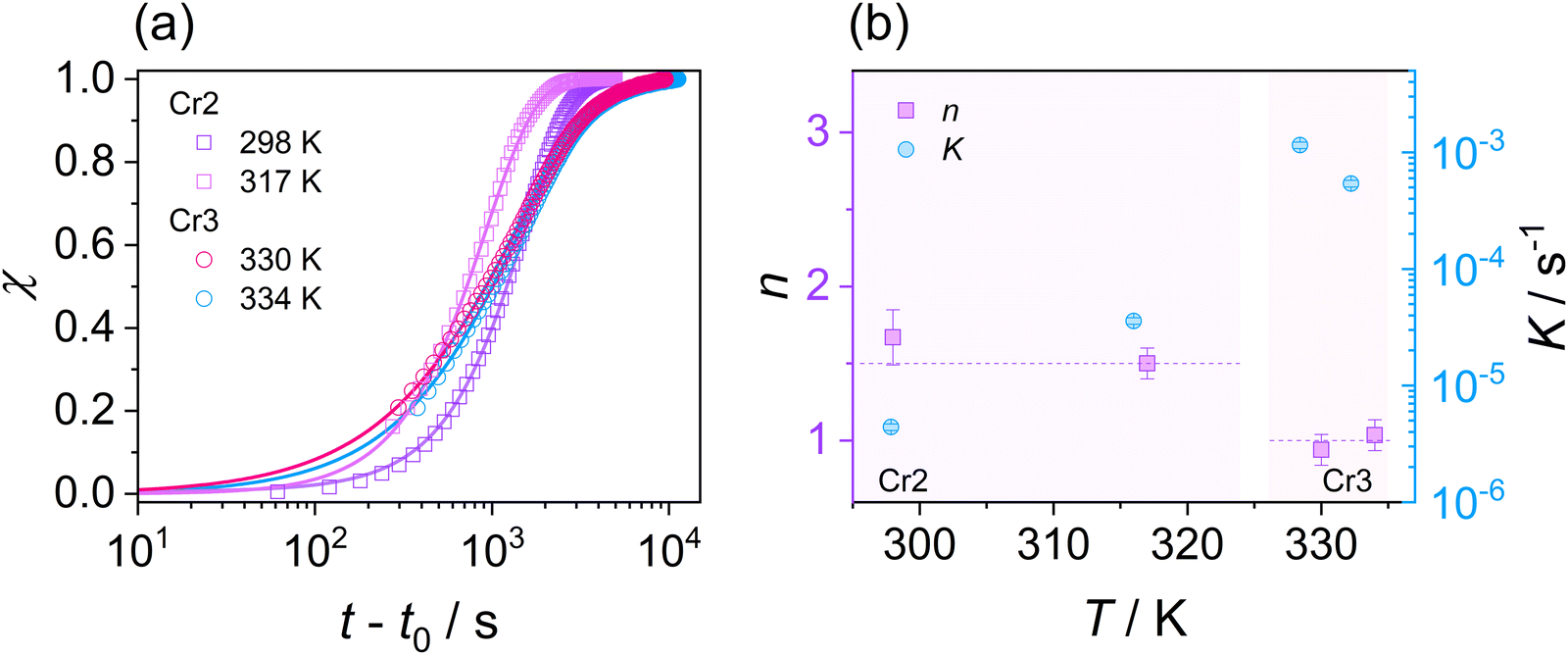 | ||
| Fig. 9 (a) Crystallinity degree χ of Cr2 and Cr3 phases as a function of an overall time for DFP25DFT. Solid lines represent the Avrami fits. (b) Avrami exponent n and crystallization rate parameter K for isothermal cold crystallization of Cr2 and Cr3 phases. Temperature ranges of Cr2 and Cr3 are highlighted. | ||
The parameter n in eqn (10) is interpreted as follows:
| n = aD + b | (11) |
Since evaluating the contribution of thermodynamic and kinetic mechanisms in the overall crystallization drive is a complex issue, their significance is assessed via a complementary manner based on the additional analysis of the process kinetics. Thus, to support the interpretation of the Avrami parameter n in identifying the main crystallization drive, we utilize approaches based on the analysis of the relation between the crystallization rate and the molecular dynamics and estimate crystallization activation energies presented in Fig. 10. Fig. 10(a) depicts the crystallization half-time t1/2, as the total time required to reach crystallinity χ = 0.5, as a function of the α-relaxation time describing the molecular mobility. This dependence reveals the coupling found for the crystallization of Cr2 with an estimated slope of 0.2. Fig. 10(b) shows an Arrhenius plot of the crystallization rate parameter K and provides the crystallization activation energy as follows:
 | (12) |
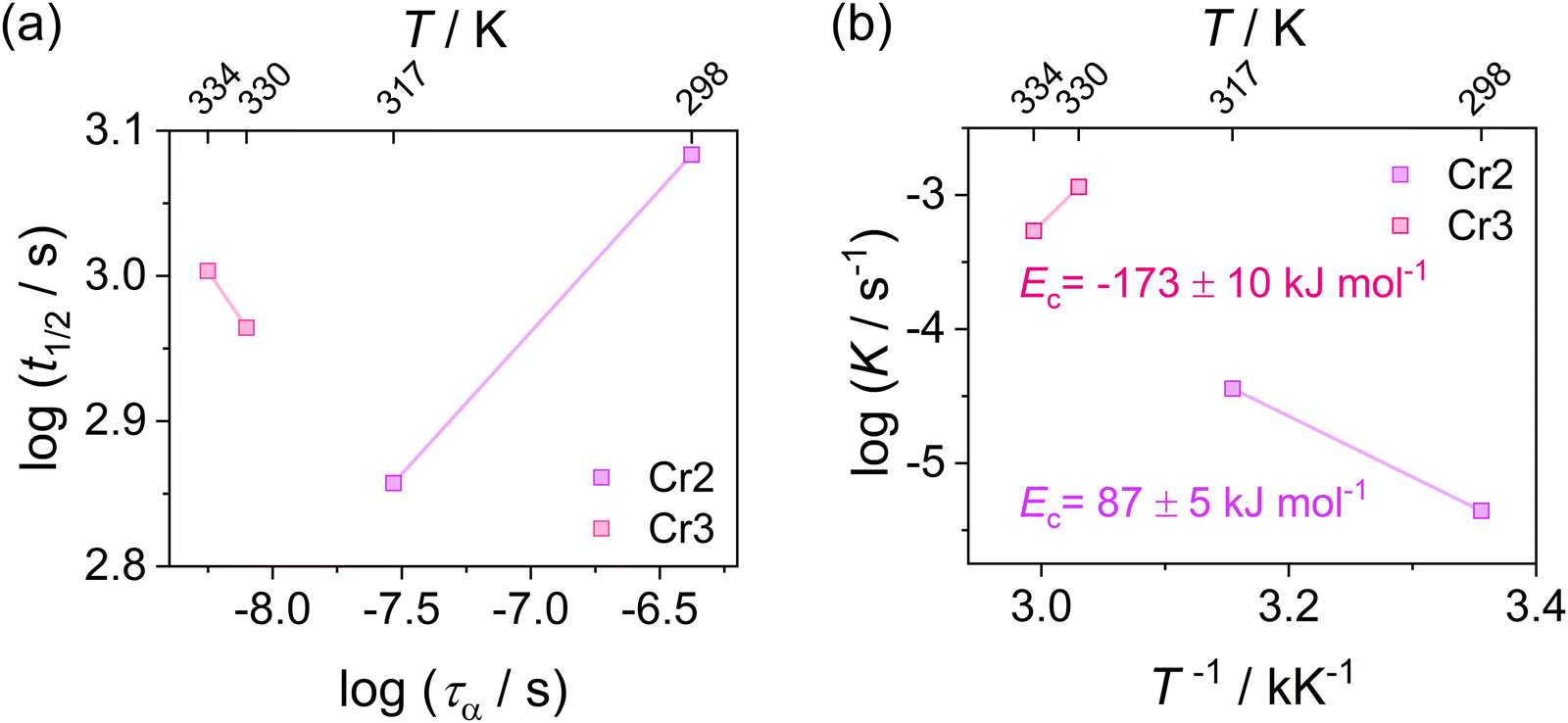 | ||
| Fig. 10 (a) Crystallization half-time t1/2 of Cr2 and Cr3 as a function of α-relaxation time in the log–log representation for DFP25DFT. (b) Crystallization activation energy Ec of Cr2 and Cr3 estimated from the Arrhenius plot of the crystallization rate parameter K. | ||
Considering the general interpretation of the Avrami exponent n (eqn (11)),80 the cold-crystallization processes of Cr2 and Cr3 proceed through two different modes. The Avrami exponent n close to 1.5 and the trend of increasing the crystallization rate parameter K with temperature suggest the three-dimensional crystal growth of the Cr2 phase, controlled by molecular diffusion, while the nucleation decayed. This interpretation is consistent with the coupling between crystallization kinetics and molecular dynamics. Accordingly, the estimated crystallization activation energy exhibits the positive value of 87 kJ mol−1. On the other hand, the cold crystallization of Cr3 is characterized by the parameter n close to 1.0, indicating that the growth of Cr3 is limited to two dimensions and proceeds from a fixed number of randomly distributed nuclei. The kinetics exposes the opposite behavior for Cr2; the crystal growth decelerates with increasing temperature and accelerating molecular mobility, as found in temperature dependences of crystallization rate parameter K and crystallization half-time. As an effect, the estimated crystallization activation energy is negative, −173 kJ mol−1. Hence, we assess the thermodynamic driving force as the primary ordering mechanism that displays its dominance in a higher temperature region, where the cold crystallization of Cr3 proceeds. The estimated crystallization activation energy |Ec| of Cr2 is similar to that of other systems of small molecules exhibiting cold crystallization of the isotropic liquid81 and slightly higher than that of some partially ordered mesophases.31,32,82 |Ec| of Cr3 is higher due to the limitations of the nucleation process in the higher temperature region and the change of the process mechanism.
The differences in the formation of Cr2 and Cr3 can be rationalized based on the additional molecular dynamics processes and the microscopic view of these phases. The activation energy Ea of the α′-process during the crystallization of Cr2 is close to the average activation energy of the process Ec, indicating the high involvement of confined molecular mobility near crystal surfaces in the crystallization mechanism. The crystal growth of Cr3 exhibits a higher absolute value of the crystallization activation energy, |Ec|, compared to the growth of Cr2. Although the thermodynamic mechanism exposes the prevalence over the diffusion drive during the crystallization of Cr3, the change in |Ec| corresponds in part to the increase in the activation energy, Ea, of the α′-process reflecting the enhancement of molecular restriction in the higher-temperature crystallization of Cr3. The increase in the activation barrier for this motion can be plausibly recognized as the factor influencing the limitation of the crystal growth of Cr3 to two dimensions, rarely found in systems of small molecules, generally exhibiting three-dimensional crystal morphologies. Molecular mobility features, growth mechanism, and nucleation behavior dominate the crystal growth dimension. Since the crystallization conditions are unchangeable in the growth of both crystals, Cr2 and Cr3, the revealed possibility of the switch in crystal morphology comes from the crystal phase change in the present case. Moreover, the difference in crystal growth dimension deduced from the Avrami model is displayed in microscopic observations (see Fig. 4(b)). The growing crystallites of Cr2 are three-dimensional spherulitic shapes, while Cr3 forms two-dimensional surfaces.
3. Conclusion
We have performed studies on polymorphism, molecular dynamics, and crystallization kinetics in DFP25DFT utilizing broadband dielectric spectroscopy studies supported by X-ray crystallography, adiabatic and differential scanning calorimetry, polarizing microscopy, and molecular simulations. The main goal of the present study was a detailed investigation of the mobility and interactions of molecules involved in the vitrification and cold-crystallization processes. The material exhibits a high tendency for glass formation and then, in reheating, two separate cold-crystallization pathways to the Cr2 and Cr3 phases. The study showed that the material possesses key features favoring cold crystallization: weak dipole–dipole interaction and sufficient molecular flexibility.Our study demonstrated that cold crystallization in DFP25DFT is facilitated by the broad distribution of structural α-relaxation times controlled by anharmonicity in the overall attraction potential determined by the weak dipole–dipole interaction. The fast rearrangement of the molecules arising from the fragile nature also favors vitrification in cooling and subsequent aggregation of the molecules in an orderly fashion in reheating.
In the liquid phase, the underlying dynamics as structural α-relaxation originates in the intermolecular rotational motion, while the secondary β-relaxation, also proceeding in the glassy state, is related to the intramolecular process. The origin of secondary relaxation was identified as the fluorinated side ring motion considering MM2 simulation results, indicating the intramolecular feature that controls the behavior of the solidification path. We found the additional motion of a part of the aggregating molecules near crystal surfaces during the immobilization process in the crystal lattice of both the Cr2 and Cr3 phases. The energy barriers for these motions reflect a higher molecular hindrance in the crystal growth of Cr3 and show that molecular mobility exposes its undoubted importance in the molecular ordering in Cr2 and Cr3. Notably, the present study demonstrates that the strength of the thermodynamic drive that depends on temperature determines its contribution.
To describe the general properties of cold crystallization and provide mechanistic insight into the processes, we analyzed the crystal growth in isothermal conditions by employing the Avrami approach combined with the analysis of the relationship between crystallization kinetics and molecular dynamics. The cold-crystallization processes proceed in different modes. The kinetic driving force controls a lower temperature region of three-dimensional crystal growth of Cr2, and the correlation between crystallization and molecular mobility rates exists. The decoupling between crystallization kinetics and molecular dynamics in a higher temperature region, where Cr3 crystallization proceeds, showed that the thermodynamic factor reveals its prevalence and drives crystal growth in twodimensions. In conclusion, the study revealed the complex nature of the cold crystallization in DFP25DFT and enabled the tune of the dimension of the crystal phase growth and the primary mechanism involved in the process.
4. Experimental
4.1 Materials
The investigated material, DFP25DFT (456.48 g mol−1) in crystalline form, was supplied by the Institute of Chemistry, Military University of Technology, Warsaw, Poland. The molecular structure revealed by the present X-ray crystallography is shown in Fig. 1. Note that the structure resolves the mystery of why the compound did not exhibit liquid crystallinity.61 The material purity was better than 99.8 mol% as determined from the endothermic melting anomaly by differential scanning calorimetry (Q200, TA Instruments, at 1 K min−1). The material was subject to other experiments without further purification.4.2 Methods
| Empirical formula | C27H24F4O2 (456.46 g mol−1) |
| Space group & Z | P21/n, Z = 4 |
| Unit cell dimensions (Å) or (°) | a = 7.7001(2) Å, b = 26.8744(7) Å, c = 11.3043(3) Å |
| α = 90°, β = 99.2084(5)°, γ = 90° | |
| Wavelength & absorption coefficient | 0.71073 Å, 0.103 mm−1 |
| Crystal size | 0.37 × 0.24 × 0.20 mm3 |
| θ range for data collection | 1.51 to 26.38° |
| Index ranges | −9 ≤ h ≤ 9, −33 ≤ k ≤ 33, −14 ≤ l ≤ 14 |
| Reflections collected (independent) | 28323 (4722 [Rint = 0.0254]) |
| Completeness to θ = 26.38° | 100.0% |
| Refinement method | Full-matrix least-squares on F2 |
| Goodness-of-fit on F2 | 1.046 |
| R indices | R 1 = 0.0421 (I > 2σ(I)), wR2 = 0.1262 (all data) |
The sample of mass 1.21820 g (2.66873 mmol) after buoyancy correction was loaded into a gold-plated calorimetry vessel. Helium gas was used as the heat conduction medium inside the vessel that was sealed at a pressure of 105 Pa at room temperature. The vessel attained thermal equilibrium within a reasonable time (1–15 min, depending on the temperature), except for transition regions (including the glass transition). The working thermometer was the platinum resistance thermometer (MINCO, S1059), the temperature scale of which was based on the ITS-90 (International Temperature Scale of 1990).88 A temperature increment by a single energy input was lower than 10−2T in the whole temperature range, and it was small enough to ignore the curvature in the temperature dependence of the apparent heat capacity. Repeated measurement runs gave essentially the same results. We obtained the thermodynamic functions for the most stable phases (Cr1 and liquid) by integrating smoothed heat capacities, as given in the ESI.†
Measurements of cold crystallization were conducted during reheating to the monitored temperature after cooling the sample to the glassy state at 173 K from the liquid state. Cold crystallization of the Cr2 phase at 298 and 317 K was recorded by continuous frequency sweeps of the range of 8 × 10⁻¹–107 Hz. Measurements for the Cr3 phase at 330 and 334 K were after the complete crystallization and melting of the Cr2 phase. The progress of crystallization was tracked by the time evolution of the real part of the dielectric permittivity ε′ at a selected frequency of 104 Hz.
Conflicts of interest
There are no conflicts to declare.Acknowledgements
T. R. acknowledges the Japan Society for the Promotion of Science for funding the JSPS Postdoctoral Fellowship for Research in Japan, ID No. P18774. This work was supported by JSPS KAKENHI 18F18774 and 20F18774.References
- S. C. Ligon, R. Liska, J. Stampfl, M. Gurr and R. Mülhaupt, Chem. Rev., 2017, 117, 10212–10290 CrossRef PubMed.
- Q. Li, Y. Xu, S. Zheng, X. Guo, H. Xue and H. Pang, Small, 2018, 14, 1800426 CrossRef.
- S.-X. Peng, Y. Cheng, J. Pries, S. Wei, H.-B. Yu and M. Wuttig, Sci. Adv., 2020, 6, eaay6726 CrossRef CAS.
- J. Vialetto, S. Rudiuk, M. Morel and D. Baigl, J. Am. Chem. Soc., 2021, 143, 11535–11543 CrossRef CAS.
- S. Yang, Y. Zhang, Y. Wang, J. Yao, L. Zhang, X. Ren, X. Li, S. Lei, X. Zhang, F. Yang, R. Li and W. Hu, Chem. Commun., 2021, 57, 2669–2672 RSC.
- G. Eda and S. A. Maier, ACS Nano, 2013, 7, 5660–5665 CrossRef CAS.
- W. Han, P. Huang, L. Li, F. Wang, P. Luo, K. Liu, X. Zhou, H. Li, X. Zhang, Y. Cui and T. Zhai, Nat. Commun., 2019, 10, 4728 CrossRef.
- C. Liu, L. Wang, J. Qi and K. Liu, Adv. Mater., 2020, 32, 2000046 CrossRef CAS.
- X. Sun, X. Liu, J. Yin, J. Yu, Y. Li, Y. Hang, X. Zhou, M. Yu, J. Li, G. Tai and W. Guo, Adv. Funct. Mater., 2017, 27, 1603300 CrossRef.
- S. Vyazovkin and N. Sbirrazzuoli, Macromol. Rapid Commun., 2006, 27, 1515–1532 CrossRef CAS.
- J. E. K. Schawe and J. F. Löffler, Nat. Commun., 2019, 10, 1337 CrossRef.
- Q. Gao, J. Ai, S. Tang, M. Li, Y. Chen, J. Huang, H. Tong, L. Xu, L. Xu, H. Tanaka and P. Tan, Nat. Mater., 2021, 20, 1431–1439 CrossRef CAS.
- M. D. Johnson, C. L. Burcham, S. A. May, J. R. Calvin, J. McClary Groh, S. S. Myers, L. P. Webster, J. C. Roberts, V. R. Reddy, C. V. Luciani, A. P. Corrigan, R. D. Spencer, R. Moylan, R. Boyse, J. D. Murphy and J. R. Stout, Org. Process Res. Dev., 2021, 25, 1284–1351 CrossRef CAS.
- K. Rautaniemi, E. Vuorimaa-Laukkanen, C. J. Strachan and T. Laaksonen, Mol. Pharm., 2018, 15, 1964–1971 CrossRef PubMed.
- M. Olbrycht, M. Balawejder, I. Poplewska, H. Lorenz, A. Seidel-Morgenstern, W. Pi
![[a with combining cedilla]](https://www.rsc.org/images/entities/char_0061_0327.gif) tkowski and D. Antos, Cryst. Growth Des., 2019, 19, 1786–1796 CrossRef.
tkowski and D. Antos, Cryst. Growth Des., 2019, 19, 1786–1796 CrossRef. - K. L. Kearns, J. Scherzer, M. Chyasnavichyus, D. Monaenkova, J. Moore, R. L. Sammler, T. Fielitz, D. A. Nicholson, M. Andreev and G. C. Rutledge, Macromolecules, 2021, 54, 2101–2112 CrossRef.
- K. Harada, T. Sugimoto, F. Kato, K. Watanabe and Y. Matsumoto, Phys. Chem. Chem. Phys., 2020, 22, 1963–1973 RSC.
- A. Toda, Thermochim. Acta, 2021, 702, 178984 CrossRef.
- B. Wunderlich, J. Chem. Phys., 1958, 29, 1395–1404 CrossRef.
- K. A. Jackson, Kinetic Processes, Wiley; 2004, vol. 44 Search PubMed.
- K. Kawakami, Pharmaceutics, 2019, 11, 202 CrossRef PubMed.
- M. T. Viciosa, N. T. Correia, M. S. Sanchez, A. L. Carvalho, M. J. Romão, J. L. Gómez Ribelles and M. Dionísio, J. Phys. Chem. B, 2009, 113, 14209–14217 CrossRef PubMed.
- K. Saito, Chemical Physics of Molecular Condensed Matter, Springer Singapore: Singapore, 2020, vol. 104 Search PubMed.
- K. Iwase, Y. Toyama, I. Yoshikawa, Y. Yamamura, K. Saito and H. Houjou, Bull. Chem. Soc. Jpn., 2018, 91, 669–677 CrossRef.
- A. Honda, S. Kakihara, M. Kawai, T. Takahashi and K. Miyamura, Cryst. Growth Des., 2021, 21, 6223–6229 CrossRef.
- K. Iwase, Y. Nagano, I. Yoshikawa, H. Houjou, Y. Yamamura and K. Saito, J. Phys. Chem. C, 2014, 118, 27664–27671 CrossRef.
- M. Kwiatkowska, I. Kowalczyk, K. Kwiatkowski and A. Zubkiewicz, Polymers, 2020, 12, 271 CrossRef.
- K. Turunen, M. R. Yazdani, A. Santasalo-Aarnio and A. Seppälä, Sol. Energy Mater. Sol. Cells, 2021, 230, 111273 CrossRef.
- A. A. Boopathi, S. Sampath and T. Narasimhaswamy, New J. Chem., 2019, 43, 9500–9506 RSC.
- Y. Tsujimoto, T. Sakurai, Y. Ono, S. Nagano and S. Seki, J. Phys. Chem. B, 2019, 123, 8325–8332 CrossRef PubMed.
- T. Rozwadowski, M. Massalska-Arodź, Ł. Kolek, K. Grzybowska, A. Bąk and K. Chłędowska, Cryst. Growth Des., 2015, 15, 2891–2900 CrossRef.
- T. Rozwadowski, Y. Yamamura and K. Saito, Cryst. Growth Des., 2021, 21, 2777–2785 CrossRef.
- K. Ishino, H. Shingai, Y. Hikita, I. Yoshikawa, H. Houjou and K. Iwase, ACS Omega, 2021, 6, 32869–32878 CrossRef PubMed.
- T. Rozwadowski, M. Jasiurkowska-Delaporte, M. Massalska-Arodź, Y. Yamamura and K. Saito, Phys. Chem. Chem. Phys., 2020, 22, 24236–24248 RSC.
- Ł. Kolek, M. Jasiurkowska-Delaporte, M. Massalska-Arodź, W. Szaj and T. Rozwadowski, J. Mol. Liq., 2020, 320, 114338 CrossRef.
- S. Sampath, A. A. Boopathi and A. B. Mandal, Phys. Chem. Chem. Phys., 2016, 18, 21251–21258 RSC.
- Y. Masuda, Sci. Rep., 2021, 11, 11304 CrossRef.
- W. R. Bodlos, S. Mattiello, A. Perinot, L. Gigli, N. Demitri, L. Beverina, M. Caironi and R. Resel, Cryst. Growth Des., 2021, 21, 325–332 CrossRef.
- C. Zheng, I. Jalan, P. Cost, K. Oliver, A. Gupta, S. Misture, J. A. Cody and C. J. Collison, J. Phys. Chem. C, 2017, 121, 7750–7760 CrossRef.
- S. Kahwaji and M. A. White, Appl. Sci., 2019, 9, 1627 CrossRef.
- A. Kimijima, A. Honda, K. Nomoto and K. Miyamura, CrystEngComm, 2019, 21, 3142–3145 RSC.
- M. Paluch, J. Knapik, Z. Wojnarowska, A. Grzybowski and K. L. Ngai, Phys. Rev. Lett., 2016, 116, 025702 CrossRef PubMed.
- A. Jedrzejowska, K. L. Ngai and M. Paluch, J. Phys. Chem. A, 2016, 120, 8781–8785 CrossRef.
- A. Stone, The Theory of Intermolecular Forces, Oxford University Press; 2013 Search PubMed.
- R. J. Greet and D. Turnbull, J. Chem. Phys., 1967, 46, 1243–1251 CrossRef.
- L. A. Deschenes and D. A. Vanden Bout, J. Phys. Chem. B, 2002, 106, 11438–11445 CrossRef.
- W. Zhang, C. W. Brian and L. Yu, J. Phys. Chem. B, 2015, 119, 5071–5078 CrossRef.
- M. K. Mapes, S. F. Swallen and M. D. Ediger, J. Phys. Chem. B, 2006, 110, 507–511 CrossRef.
- R. Meier, E. Schneider and E. A. Rössler, J. Chem. Phys., 2015, 142, 034503 CrossRef PubMed.
- J. Soetbeer, L. F. Ibáñez, Z. Berkson, Y. Polyhach and G. Jeschke, Phys. Chem. Chem. Phys., 2021, 23, 21664–21676 RSC.
- M. Becher, R. Horstmann, S. Kloth, E. A. Rössler and M. Vogel, J. Phys. Chem. Lett., 2022, 13, 4556–4562 CrossRef PubMed.
- S. Karmakar, T. Mandal and J. Dash, Eur. J. Org. Chem., 2019, 5916–5924 CrossRef.
- Y. Tao, C. Yang and J. Qin, Chem. Soc. Rev., 2011, 40, 2943 RSC.
- L. H. Heitman, R. Narlawar, H. de Vries, M. N. Willemsen, D. Wolfram, J. Brussee and A. P. IJzerman, J. Med. Chem., 2009, 52, 2036–2042 CrossRef CAS PubMed.
- T. Butler, F. Wang, M. L. Daly, C. A. DeRosa, D. A. Dickie, M. Sabat and C. L. Fraser, J. Phys. Chem. C, 2019, 123, 25788–25800 CrossRef.
- D. Deng, Y. Zhang, J. Zhang, Z. Wang, L. Zhu, J. Fang, B. Xia, Z. Wang, K. Lu, W. Ma and Z. Wei, Nat. Commun., 2016, 7, 13740 CrossRef PubMed.
- S. Subramanian, S. K. Park, S. R. Parkin, V. Podzorov, T. N. Jackson and J. E. Anthony, J. Am. Chem. Soc., 2008, 130, 2706–2707 CrossRef PubMed.
- N. Nanbu, M. Takehara, S. Watanabe, M. Ue and Y. Sasaki, Bull. Chem. Soc. Jpn., 2007, 80, 1302–1306 CrossRef.
- J. Ge, L. Xie, R. Peng, B. Fanady, J. Huang, W. Song, T. Yan, W. Zhang and Z. Ge, Angew. Chem., Int. Ed., 2020, 59, 2808–2815 CrossRef PubMed.
- D. Rauber, P. Zhang, V. Huch, T. Kraus and R. Hempelmann, Phys. Chem. Chem. Phys., 2017, 19, 27251–27258 RSC.
- R. Dąbrowski, J. Dziaduszek, K. Garbat, S. Urban, M. Filipowicz, J. Herman, M. Czerwiński and P. Harmata, Liq. Cryst., 2017, 44, 1534–1548 CrossRef.
- S. Havriliak and S. Negami, J. Polym. Sci., Part C: Polym. Lett., 1966, 14, 99–117 CrossRef.
- S. Havriliak and S. Negami, Polymer, 1967, 8, 161–210 CrossRef CAS.
- F. Kremer and A. Schönhals, ed., Broadband Dielectric Spectroscopy, Springer Berlin Heidelberg: Berlin, Heidelberg, 2003 Search PubMed.
- H. Vogel, Phys. Z., 1921, 22, 645–646 Search PubMed.
- G. S. Fulcher, J. Am. Ceram. Soc., 1925, 8, 339–355 CrossRef.
- G. Tammann and W. Hesse, Z. Anorg. Allg. Chem., 1926, 156, 245–257 CrossRef.
- C. A. Angell, J. Non-Cryst. Solids, 1991, 131–133, 13–31 CrossRef.
- H. Tanaka, J. Non-Cryst. Solids, 2005, 351, 3371–3384 CrossRef.
- A. Sanz, A. Nogales and T. A. Ezquerra, Macromolecules, 2010, 43, 29–32 CrossRef CAS.
- K. Adrjanowicz, K. Kaminski, Z. Wojnarowska, M. Dulski, L. Hawelek, S. Pawlus, M. Paluch and W. Sawicki, J. Phys. Chem. B, 2010, 114, 6579–6593 CrossRef CAS PubMed.
- F. Alvarez, A. Alegra and J. Colmenero, Phys. Rev. B: Condens. Matter Mater. Phys., 1991, 44, 7306–7312 CrossRef PubMed.
- S. L. Shamblin, B. C. Hancock, Y. Dupuis and M. J. Pikal, J. Pharm. Sci., 2000, 89, 417–427 CrossRef CAS.
- H. Eyring, J. Chem. Phys., 1936, 4, 283–291 CrossRef CAS.
- H. W. Starkweather, Polymer, 1991, 32, 2443–2448 CrossRef CAS.
- M. Avrami, J. Chem. Phys., 1939, 7, 1103–1112 CrossRef CAS.
- M. Avrami, J. Chem. Phys., 1940, 8, 212–224 CrossRef CAS.
- R. S. Stein and A. Misra, J. Polym. Sci., Part A-2, 1973, 11, 109–116 CrossRef CAS.
- A. M. González-Delgado, M. Pérez-Morales, J. J. Giner-Casares, E. Muñoz, M. T. Martín-Romero and L. Camacho, J. Phys. Chem. B, 2009, 113, 13249–13256 CrossRef PubMed.
- Q. Zheng, Y. Zhang, M. Montazerian, O. Gulbiten, J. C. Mauro, E. D. Zanotto and Y. Yue, Chem. Rev., 2019, 119, 7848–7939 CrossRef CAS PubMed.
- R. Chang, Q. Fu, Y. Li, M. Wang, W. Du, C. Chang and A. Zeng, CrystEngComm, 2017, 19, 335–345 RSC.
- Ł. Kolek, M. Jasiurkowska-Delaporte, E. Juszyńska-Gałązka and T. Rozwadowski, J. Mol. Liq., 2021, 339, 117076 CrossRef.
- SAINT (V6.45A), Bruker AXS Inc.: Madison, Wisconsin, USA Search PubMed.
- SADABS-2016/2, Bruker AXS Inc.: Madison, Wisconsin, USA Search PubMed.
- G. M. Sheldrick, Acta Crystallogr., Sect. A: Found. Crystallogr., 2008, 64, 112–122 CrossRef PubMed.
- G. M. Sheldrick, Acta Crystallogr., Sect. C: Struct. Chem., 2015, 71, 3–8 Search PubMed.
- Y. Yamamura, K. Saito, H. Saitoh, H. Matsuyama, K. Kikuchi and I. Ikemoto, J. Phys. Chem. Solids, 1995, 56, 107–115 CrossRef.
- H. Preston-Thomas, Metrologia, 1990, 27, 3–10 CrossRef.
Footnote |
| † Electronic supplementary information (ESI) available. CCDC 2164890. For ESI and crystallographic data in CIF or other electronic format see DOI: https://doi.org/10.1039/d2cp03638j |
| This journal is © the Owner Societies 2023 |