
 Open Access Article
 This Open Access Article is licensed under a Creative Commons Attribution-Non Commercial 3.0 Unported Licence
Anodic instability of carbon in non-alkaline Zn–air batteries†
Roman R.
Kapaev
 * and
Malachi
Noked
*
* and
Malachi
Noked
*
Department of Chemistry and BINA – BIU Center for Nanotechnology and Advanced Materials, Bar-Ilan University, Ramat-Gan 5290002, Israel. E-mail: kapaevr@biu.ac.il; malachi.noked@biu.ac.il
First published on 18th July 2023
Abstract
Although non-alkaline rechargeable Zn–air batteries (RZABs) are promising for energy storage, their chemistry is still underdeveloped and unclear. It was suggested that using Zn(OAc)2 or Zn(OTf)2 aqueous solutions as electrolytes enables reversible, corrosion-free charge–discharge processes, but the anodic stability of carbon in these cells has remained poorly studied. We report that CO2 evolution is manifested during the oxygen evolution reaction in non-alkaline RZABs, which is associated with the corrosion of carbon scaffolds. This corrosion is observed for different electrolyte compositions, such as Zn(OAc)2, ZnSO4 and Zn(OTf)2 solutions of various concentrations. The corrosion rate decreases when the overpotentials during the oxygen evolution reaction are lower. This study underlines the importance of addressing the anodic instability of carbon in non-alkaline RZABs.
Rechargeable Zn–air batteries (RZABs) are a promising technology for energy storage, which can potentially offer high energy density, low cost, and safety.1–3 Most of the research in this area pertains to alkaline Zn–air batteries that employ a Zn metal negative electrode (anode), an oxygen-breathing positive electrode (cathode), and a strongly basic electrolyte, such as 6M KOH.1,4 However, there are several drawbacks that limit their performance and impede practical applications.5 There is uneven vertical growth of Zn and passivation of the Zn anode, which makes the batteries unstable.6,7 Continuous corrosion of zinc occurs in alkaline electrolytes, resulting in the loss of active Zn and fast cell degradation.7 Consumption of CO2 from the atmosphere, which is inevitable if ambient air is used, leads to clogging of the cathodes with K2CO3.8 Finally, a significant problem is the corrosion of carbon that was reported in alkaline RZABs.9–12 The oxidation of carbon results in catalytic activity loss and the formation of the same K2CO3 that clogs the pores of positive electrodes.
Many of these problems can be circumvented by using non-alkaline electrolytes. Zinc anodes are more stable in near-neutral media, resulting in higher coulombic efficiency and generally smoother plating-stripping behavior.13 Additionally, irreversible CO2 uptake is no longer a critical problem in non-alkaline systems.14,15 It could be suggested that corrosive processes should also be suppressed in less aggressive environments of mild electrolytes. However, the anodic stability of carbon in non-alkaline RZABs has not been studied thoroughly. Sun et al.14 reported that no CO2 evolution was observed with 1 M Zn(OTf)2 electrolyte, although their cells could be easily overcharged, which indicates the presence of a parasitic oxidation reaction at the positive electrode side. 1 M Zn(OAc)2 was also reported as a promising electrolyte that might enable stable cycling,15 but corrosion of carbon was not studied for this system. Here we gain a detailed insight into the anodic stability of carbon in RZABs with various non-alkaline electrolytes using online electrochemical mass spectrometry (OEMS) and complementary techniques.
Initially, aqueous 1 M solutions of Zn(OAc)2, ZnSO4 and Zn(OTf)2 were selected as electrolytes. Acetate- and triflate-based compositions were reported to be promising for RZABs,14,15 and the sulfate-based solution is attractive because of low cost and electrochemical stability of the SO42− anion. Carbon black (Ketjenblack EC300J) was selected as a model cathode material. The cathode substrate was hydrophobic carbon black (Sigracet 39BB), which is electrochemically inactive in the operational voltage range of the cells.16 Sealed cells that have reservoirs filled with ambient air16 were subjected to galvanostatic cycling at 1 mA cm−2 with a fixed capacity of 1 mA h cm−2. Details are available in the Experimental section.
As shown in Fig. 1, CO2 evolution is observed during the OEMS experiments for the cells with all electrolyte compositions. Carbon dioxide evolves only during the charge step, which corresponds to the oxygen evolution reaction (OER) at the positive electrode. At the first cycle, the CO2 evolution rate is smaller with the triflate-based electrolyte, but it increases during subsequent cycling (Fig. 1c). A similar trend is observed with the acetate-based electrolyte during the initial cycles. However, the CO2 evolution rate stabilizes after the first three cycles (Fig. S1a, ESI†).
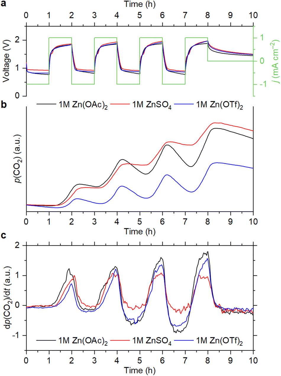 | ||
| Fig. 1 Cell voltage and current density vs. time (a), evolution of the CO2 partial pressure (b) and its derivative (c) during the OEMS measurements with 1 M electrolytes. | ||
After four cycles, the cells were left at an open-circuit voltage (OCV). It is seen that the partial pressure of CO2 slowly decreases during the OCV step, which is because air is continuously evacuated for mass-spectrometry sampling. Decrease of the CO2 content is also observed during the cell discharge, which corresponds to the oxygen reduction reaction (ORR). However, it becomes faster upon cycling than during the OCV step (Fig. 1b, c and Fig. S1, ESI†). Since electrochemical reduction of CO2 is completely inhibited when the O2 concentration is high, it cannot cause a pronounced decrease of the CO2 level.17 This indicates that absorption of CO2 by the electrolytes takes place during the ORR. It should be noted that 4e− O2 reduction is observed with each of the selected electrolytes (see Section S1, ESI†), which is accompanied by the generation of OH− ions.14,15,18 Therefore, it is suggested that absorption of CO2 is associated with an increase of pH, which was previously reported for non-alkaline RZABs.14,18 It is seen that the CO2 uptake becomes more pronounced upon cycling. With the Zn(OAc)2 and Zn(OTf)2 solutions, this effect becomes obvious after two cycles (Fig. 1c); with the ZnSO4 solution, it becomes evident after four cycles (Fig. S1b, ESI†). Supposedly, pH gradually increases due to the accumulation of discharge products, eventually reaching values that promote the absorption of carbon dioxide. Further studies of the pH evolution in the cells are required to understand this phenomenon.
For the triflate- and sulfate-based systems, the only source of evolving CO2 is the corrosion of the carbon scaffold. For Zn(OAc)2, however, decarboxylation of acetate ions according to the Kolbe reaction is also possible.19 To determine if acetate oxidation takes place, we monitored 12CO2/13CO2 evolution during cycling with a 1 M solution of labeled zinc acetate, Zn(13CH313CO2)2. It is seen in Fig. 2 that the evolution of 12CO2 is mostly observed. The ratio between the 13CO2 and 12CO2 signal intensities does not increase during the OER steps. Therefore, the decomposition of acetate is absent, and CO2 evolution is associated solely with the corrosion of the carbon electrodes.
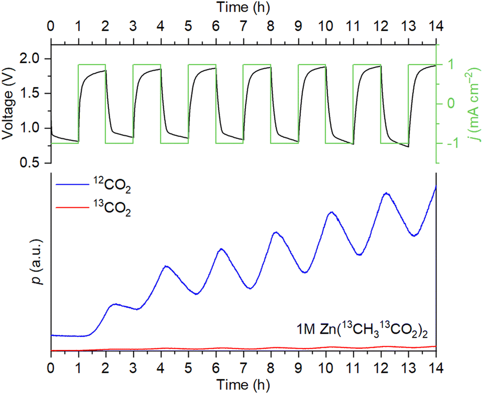 | ||
| Fig. 2 Cell voltage/current density vs. time and evolution of 12CO2/13CO2 during the OEMS measurements with 1 M Zn(13CH313CO2)2 as the electrolyte. | ||
To track the evolution of the carbon surface, we compared the C1s X-ray photoelectron spectra (XPS) of the electrodes before and after cycling. The cell with 1 M ZnSO4 solution was selected as a model system to avoid interference with carbon atoms from the electrolyte. In the corroded electrode, the peak at 286 eV, which corresponds to C–O groups,20,21 has an increased relative intensity (Fig. 3a). The estimated content of C–O carbons raises from 11% to 16% at. after ten cycles. Additionally, Raman spectroscopy shows that corrosion leads to a decrease of the D/G and D*/G band ratios (Fig. 3b), which correspond to disordered domains in carbon black.22–24 Therefore, the disordered domains are more susceptible to oxidation than graphitic sp2 domains, which is in accordance with the literature.25–27 In the scanning electron microscopy (SEM) images, hexagonal platelets are observed in the electrode after cycling (Fig. 3c). These particles are attributed to the zinc hydroxysulfate discharge product,14 which does not decompose completely during the OER because the charge–discharge is only partially reversible.
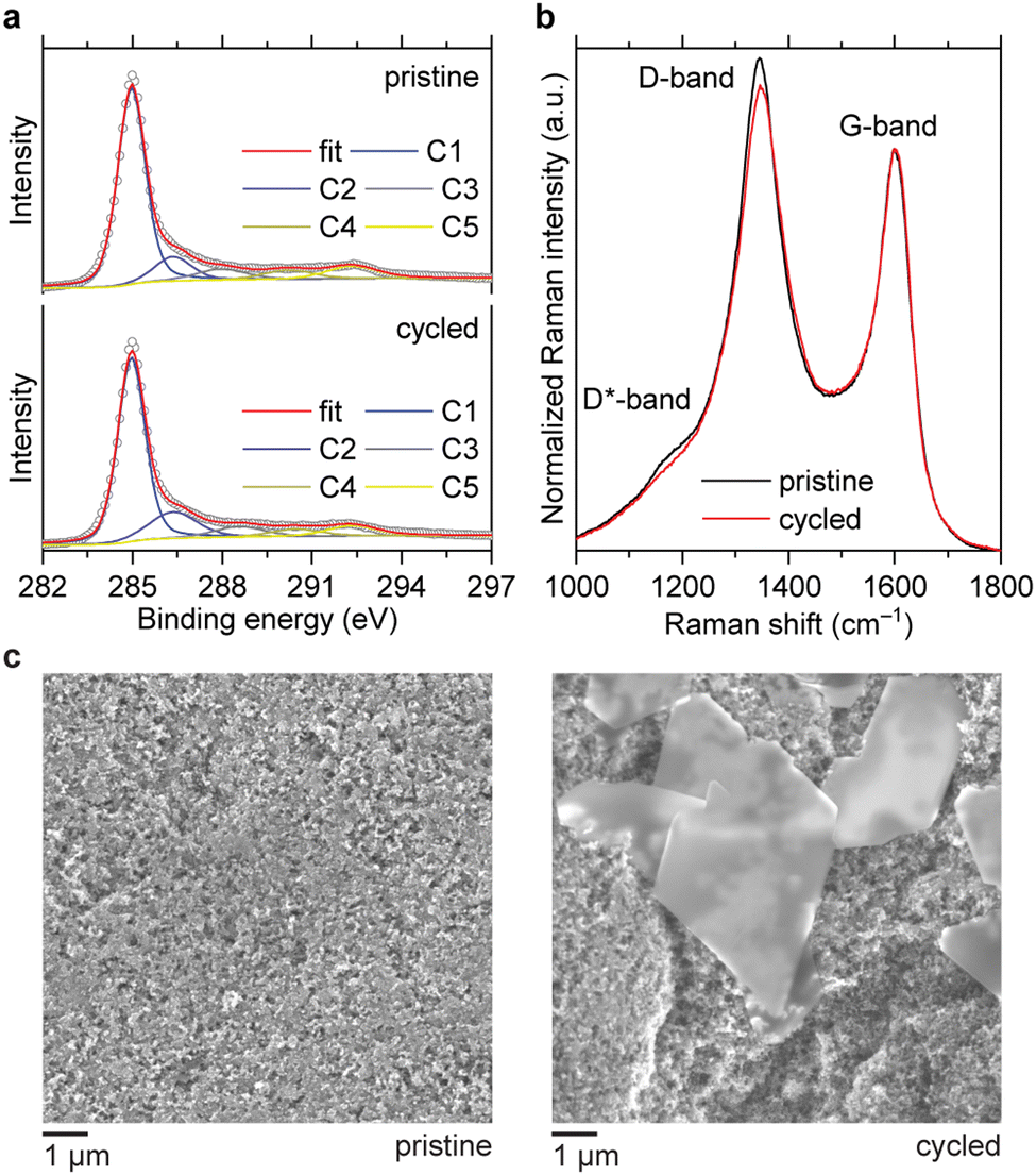 | ||
| Fig. 3 XPS (a), Raman spectra (b) and SEM images (c) of the carbon electrodes before and after 10 cycles at 1 mA cm−2 with a fixed capacity of 1 mA h cm−2. The electrolyte was 1 M ZnSO4. | ||
A popular strategy to improve the stability of batteries at high voltages is to increase the salt concentration in the electrolytes.28 To see if carbon corrosion can be mitigated using this approach, we performed comparative OEMS experiments with different salt concentrations. The data indicate that using more concentrated electrolytes does not lead to any substantial decrease of the CO2 evolution rate during the OER (Fig. S2, ESI†). On the other hand, it is seen that CO2 absorption during the ORR is slightly less pronounced when concentrated Zn(OAc)2 and Zn(OTf)2 solutions are used. This is likely associated with the higher buffering capacity of the concentrated electrolytes, which decreases the variation of pH upon cycling.
To see how the corrosion depends on the OER performance of carbons, we compared the CO2 evolution rates for Ketjenblack EC300J and Ketjenblack EC600JD. These carbons have almost identical particle size, graphitization degree, surface chemistry and wettability properties, but EC600JD has a higher specific surface area (1444 m2 g−1vs. 451 m2 g−1), which results in lower OER overpotentials.16 Despite a more developed surface of EC600JD, which should make it more susceptible to oxidation,29 it is observed that the CO2 evolution rate for EC600JD is lower than for EC300J (Fig. 4). Therefore, it might be concluded that the carbon corrosion rate might be mitigated by decreasing the OER overpotentials. This is also confirmed by running OEMS at different current rates (0.5 and 1 mA cm−2). Applying smaller current results in lower overpotentials, and lower CO2 evolution rates are observed accordingly (Fig. S3, ESI†).
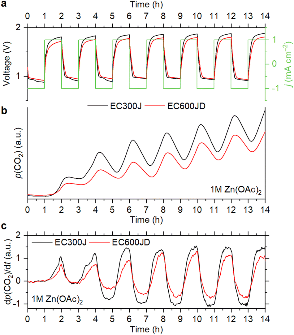 | ||
| Fig. 4 Cell voltage and current density vs. time (a), evolution of CO2 partial pressure (b) and its derivative (c) during the OEMS measurements with different types of carbon black. The electrolyte was 1 M Zn(OAc)2. | ||
To summarize, this study shows that oxidation of carbon takes place during the OER in non-alkaline RZABs. Carbon corrosion is observed for Zn(OAc)2, Zn(OTf)2 and ZnSO4-based electrolytes with various salt concentrations. Additionally, we demonstrate that acetate anions are stable during the OER, and CO2 absorption occurs during the ORR, presumably because of a pH increase that takes place upon cell discharging. Overall, the results highlight that addressing the anodic instability of positive electrodes is crucial for non-alkaline Zn–air batteries. Suggested ways to suppress the carbon corrosion include enhancement of the OER kinetics and increasing the graphitization degree. Supposedly, the corrosion might also be circumvented by depositing protective coatings at the carbon surfaces.
R. R. K. and M. N. conceived the project. R. R. K. designed and performed the experiments and wrote the manuscript. M. N. edited the manuscript and supervised the project.
This work was financially supported by Nichia Corporation. The authors thank their colleagues from Bar-Ilan University: Michal Ejgenberg for XPS measurements, Amit Ohayon for SEM measurements, and Sri Harsha Akella for the help with OEMS measurements.
Conflicts of interest
There are no conflicts to declare.References
- K. W. Leong, Y. Wang, M. Ni, W. Pan, S. Luo and D. Y. C. Leung, Renew. Sustainable Energy Rev., 2022, 154, 111771 CrossRef CAS.
- J. W. Choi and D. Aurbach, Nat. Rev. Mater., 2016, 1, 16013 CrossRef CAS.
- Q. Liu, L. Wang and H. Fu, J. Mater. Chem. A, 2023, 11, 4400–4427 RSC.
- Y. Wei, Y. Shi, Y. Chen, C. Xiao and S. Ding, J. Mater. Chem. A, 2021, 9, 4415–4453 RSC.
- D. Deckenbach and J. J. Schneider, Adv. Mater. Interfaces, 2023, 10, 2202494 CrossRef CAS.
- J. Zhang, Q. Zhou, Y. Tang, L. Zhang and Y. Li, Chem. Sci., 2019, 10, 8924–8929 RSC.
- J. Yi, P. Liang, X. Liu, K. Wu, Y. Liu, Y. Wang, Y. Xia and J. Zhang, Energy Environ. Sci., 2018, 11, 3075–3095 RSC.
- S. Zhao, T. Liu, J. Wang, I. Temitope Bello, Y. Zuo, M. Wei, K. Wang, K. K. S. Lau and M. Ni, Chem. Eng. J., 2022, 450, 138207 CrossRef CAS.
- Y. He, W. Shang, M. Ni, Y. Huang, H. Zhao and P. Tan, Chem. Eng. J., 2022, 427, 130862 CrossRef CAS.
- T. Wang, M. Kunimoto, T. Mori, M. Yanagisawa, J. Niikura, I. Takahashi, M. Morita, T. Abe and T. Homma, J. Power Sources, 2022, 533, 231237 CrossRef CAS.
- Z. Zhao, W. Yu, W. Shang, Y. He, Y. Ma, Z. Zhang and P. Tan, J. Power Sources, 2022, 543, 231844 CrossRef CAS.
- S. Möller, S. Barwe, J. Masa, D. Wintrich, S. Seisel, H. Baltruschat and W. Schuhmann, Angew. Chem., Int. Ed., 2020, 59, 1585–1589 CrossRef PubMed.
- C. Li, L. Wang, J. Zhang, D. Zhang, J. Du, Y. Yao and G. Hong, Energy Storage Mater., 2022, 44, 104–135 CrossRef.
- W. Sun, F. Wang, B. Zhang, M. Y. Zhang, V. Kupers, X. Ji, C. Theile, P. Bieker, K. Xu, C. S. Wang and M. Winter, Science, 2021, 371, 46–51 CrossRef CAS PubMed.
- W. Sun, V. Küpers, F. Wang, P. Bieker and M. Winter, Angew. Chem., Int. Ed., 2022, 61, e202207353 CAS.
- R. R. Kapaev, A. Ohayon, M. Sonoo, J. Tzadikov, M. Shalom and M. Noked, Electrochim. Acta, 2023, 456, 142462 CrossRef CAS.
- Y. Xu, J. P. Edwards, J. Zhong, C. P. O’Brien, C. M. Gabardo, C. McCallum, J. Li, C.-T. Dinh, E. H. Sargent and D. Sinton, Energy Environ. Sci., 2020, 13, 554–561 RSC.
- S. Clark, A. R. Mainar, E. Iruin, L. C. Colmenares, J. A. Blázquez, J. R. Tolchard, A. Latz and B. Horstmann, J. Mater. Chem. A, 2019, 7, 11387–11399 RSC.
- N. Sbei, S. Aslam and N. Ahmed, React. Chem. Eng., 2021, 6, 1342–1366 RSC.
- J. Park, W. Lee, J. Nam, J. T. Han, C.-J. Choi and J. Y. Hwang, Carbon, 2022, 189, 579–585 CrossRef CAS.
- I. Ferrari, A. Motta, R. Zanoni, F. A. Scaramuzzo, F. Amato, E. A. Dalchiele and A. G. Marrani, Carbon, 2023, 203, 29–38 CrossRef CAS.
- A. Y. Lee, K. Yang, N. D. Anh, C. Park, S. M. Lee, T. G. Lee and M. S. Jeong, Appl. Surf. Sci., 2021, 536, 147990 CrossRef CAS.
- S. Potgieter-Vermaak, N. Maledi, N. Wagner, J. H. P. Van Heerden, R. Van Grieken and J. H. Potgieter, J. Raman Spectrosc., 2011, 42, 123–129 CrossRef CAS.
- A. Sadezky, H. Muckenhuber, H. Grothe, R. Niessner and U. Pöschl, Carbon, 2005, 43, 1731–1742 CrossRef CAS.
- L. Dubau, L. Castanheira, F. Maillard, M. Chatenet, O. Lottin, G. Maranzana, J. Dillet, A. Lamibrac, J.-C. Perrin, E. Moukheiber, A. ElKaddouri, G. De Moor, C. Bas, L. Flandin and N. Caqué, Wiley Interdiscip. Rev.: Energy Environ., 2014, 3, 540–560 CAS.
- J. Yang, S. Park, K. Y. Choi, H.-S. Park, Y.-G. Cho, H. Ko and H.-K. Song, ACS Sustainable Chem. Eng., 2018, 6, 9566–9571 CrossRef CAS.
- Y. Yi, G. Weinberg, M. Prenzel, M. Greiner, S. Heumann, S. Becker and R. Schlögl, Catal. Today, 2017, 295, 32–40 CrossRef CAS.
- Y. Yamada, J. Wang, S. Ko, E. Watanabe and A. Yamada, Nat. Energy, 2019, 4, 269–280 CrossRef CAS.
- S. C. Ball, S. L. Hudson, D. Thompsett and B. Theobald, J. Power Sources, 2007, 171, 18–25 CrossRef CAS.
Footnote |
| † Electronic supplementary information (ESI) available. See DOI: https://doi.org/10.1039/d3cc02458j |
| This journal is © The Royal Society of Chemistry 2023 |