
 Open Access Article
 This Open Access Article is licensed under a Creative Commons Attribution-Non Commercial 3.0 Unported Licence
Optimizing LiMn1.5M0.5O4 cathode materials for aqueous photo-rechargeable batteries†
Kohei
Shimokawa
 *ab,
Shogo
Matsubara
c,
Tomoya
Kawaguchi
b,
Akihiro
Okamoto
defg and
Tetsu
Ichitsubo
*bh
*ab,
Shogo
Matsubara
c,
Tomoya
Kawaguchi
b,
Akihiro
Okamoto
defg and
Tetsu
Ichitsubo
*bh
aFrontier Research Institute for Interdisciplinary Sciences, Tohoku University, 6-3 Aramaki Aza Aoba, Aoba-ku, Sendai 980-8578, Japan. E-mail: kohei.shimokawa.b7@tohoku.ac.jp
bInstitute for Materials Research, Tohoku University, 2-1-1 Katahira, Aoba-ku, Sendai 980-8577, Japan. E-mail: tichi@imr.tohoku.ac.jp
cDepartment of Life Science and Applied Chemistry, Graduate School of Engineering, Nagoya Institute of Technology, Gokiso-cho, Show-ku, Nagoya 466-8555, Japan
dInternational Center for Materials Nanoarchitectonics (WPI-MANA), National Institute for Materials Science, 1-1 Namiki, Tsukuba, Ibaraki 305-0044, Japan
eResearch Center for Macromolecules and Biomaterials, National Institute for Materials Science, 1-1 Namiki, Tsukuba, 305-0044, Japan
fGraduate School of Chemical Sciences and Engineering, Hokkaido University, North 13 West 8, Kita-ku, Sapporo, Hokkaido 060-8628, Japan
gGraduate School of Science and Technology, University of Tsukuba, 1-1-1 Tennodai, Tsukuba, 305-8577, Japan
hAdvanced Science Research Center, Japan Atomic Energy Agency, 2-4 Shirakata, Tokai-mura, Naka-gun, Ibaraki 319-1195, Japan
First published on 6th June 2023
Abstract
Spinel oxides are promising for high-potential cathode materials of photo-rechargeable batteries. However, LiMn1.5M0.5O4 (M = Mn) shows a rapid degradation during charge/discharge under the illumination of UV-visible light. Here, we investigate various spinel-oxide materials by modifying the composition (M = Fe, Co, Ni, Zn) to demonstrate photocharging in a water-in-salt aqueous electrolyte. LiMn1.5Fe0.5O4 exhibited a substantially higher discharge capacity compared to that of LiMn2O4 after long-term photocharging owing to enhanced stability under illumination. This work provides fundamental design guidelines of spinel-oxide cathode materials for the development of photo-rechargeable batteries.
Energy harvesting and storage from renewable sources is one of the most important issues for achieving a sustainable society. Solar cells can supply electricity from sunlight; however, they must be connected to rechargeable batteries for storing energy. Photo-rechargeable batteries (PRBs),1,2 which can generate and store electricity in one device, are promising to address this problem. Since the first report in 1976,3 the development of PRBs has been limited by the lack of suitable electrode materials. Nevertheless, PRBs are now attracting much attention due to the growing demand for next-generation batteries. In addition, PRBs are expected to be used for internet of things (IoT) devices, where photocharging would significantly improve the utility of such wireless devices. Various configurations of PRBs have been proposed so far,4–12 and they roughly fall into two types: three-7–9 and two-electrode4–6,10–12 systems. The two-electrode design is suitable for reducing the cost and size owing to the absence of an additional photoelectrode.1,2 Furthermore, tailoring the electrode materials is important to improve the performance and the feasibility of practical applications.13–16
Our group recently reported the photocharging of LiMn2O4, in which we employed a half-cell with an electron acceptor to demonstrate Li extraction from the spinel structure induced by the holes generated in TiO2 nanoparticles.17 Spinel LiMn2O4 is promising for a high-potential cathode; however, a problem is its low stability during charge/discharge. For instance, it is well known that Mn2+ formed by the disproportionation of Mn3+ in LiMn2O4 easily dissolves into electrolytes,18 resulting in capacity fading. The disproportionation is considered to be accelerated under illumination due to the photoexcitation of electrons in Mn d-orbitals.19,20 Thus, the stability should be enhanced by materials design to improve the battery performance.
To investigate the stability of LiMn2O4 under illumination, we performed cyclic voltammetry (CV) in a water-in-salt LiTFSA (TFSA: bis(trifluoromethanesulfonyl)amide) solution, which is a highly-concentrated aqueous electrolyte21 used in our previous work.17 LiMn2O4 showed high cyclability in the dark;17 however, as shown in Fig. 1, a rapid capacity fading was observed under the illumination of UV-visible light (300–600 nm; ∼0.36 W cm−2) to the electrode. This indicates that the degradation of LiMn2O4 was significantly accelerated under illumination. A conventional way to improve the stability against disproportionation is substituting a part of the Mn in LiMn2O4 with other elements.22–24 Considering that the disproportionation proceeds with multiple Mn3+ cations in the structure, decreasing the density of Mn3+ is effective for preventing it. The molar ratio of Mn3+/Mn4+, which is 1 for LiMn2O4, can be tuned by partially substituting Mn with other elements. In the case of LiMn1.5M0.5O4, it becomes as follows: (i) when M is another trivalent cation (e.g., Fe3+, Co3+), the Mn3+ density decreases to half (Mn3+/Mn4+ = 0.5), (ii) when M is a divalent cation (e.g., Ni2+, Zn2+), Mn3+ is ideally absent in the spinel structure (Mn3+/Mn4+ = 0). However, a drawback is a decrease in the capacity due to the lowered number of Mn3+ cations,25 which can be oxidized in charging. We, therefore, hypothesized that trivalent M is suitable for the LiMn1.5M0.5O4 cathode of PRBs in terms of the balance of capacity and stability, as shown in Fig. 2(a).
 | ||
| Fig. 1 CV profiles of LiMn2O4 under the illumination of UV-visible light (300–600 nm) in 21 M LiTFSA/H2O. | ||
 | ||
| Fig. 2 (a) Overview of the materials design strategy in this study. (b) XRD profiles of the synthesized LiMn1.5M0.5O4 (M = Fe, Co, Ni, Zn) after calcination at 500 °C for 4 h. | ||
We prepared four kinds of spinel-oxide cathode materials using Fe, Co, Ni, and Zn (Fig. 2(b)), based on previous works.22–25 A solution combustion method was used for their synthesis.26 The obtained materials were further calcined at 500 °C in an air atmosphere to remove the impurity phases and improve the crystallinity (Fig. S1–S5, ESI†). Their X-ray diffraction (XRD) profiles were analysed by the Rietveld method. The crystalline size was estimated to be ∼10 nm for all the compositions (Fig. S6a, ESI†). LiMn1.5Fe0.5O4 exhibited the largest lattice constant (Fig. S6b, ESI†), which is reasonable because Fe3+ in the high-spin state shows a large ionic radius in relation to the other substituting elements in the spinel structure.27 Almost all Li ions were found to be located at the tetrahedral 8a site in the Fd![[3 with combining macron]](https://www.rsc.org/images/entities/char_0033_0304.gif) m space group (i.e., normal spinel), except for LiMn1.5Zn0.5O4 due to the strong preference of Zn for the tetrahedral site (Fig. S6c, ESI†).27,28 This results in the enhanced intensity of the diffraction peak at ∼31° for LiMn1.5Zn0.5O4. Distributions of particle size were measured with a nanoparticle tracking analyser (NTA) as well as a scanning electron microscope (SEM), where the average values were approximately 200 nm (Fig. S7, ESI†). Furthermore, the compositions of the synthesized materials were confirmed by inductively coupled plasma optical emission spectroscopy (ICP-OES). The obtained molar ratios of Mn/M were almost the same as the nominal compositions (Table S1, ESI†).
m space group (i.e., normal spinel), except for LiMn1.5Zn0.5O4 due to the strong preference of Zn for the tetrahedral site (Fig. S6c, ESI†).27,28 This results in the enhanced intensity of the diffraction peak at ∼31° for LiMn1.5Zn0.5O4. Distributions of particle size were measured with a nanoparticle tracking analyser (NTA) as well as a scanning electron microscope (SEM), where the average values were approximately 200 nm (Fig. S7, ESI†). Furthermore, the compositions of the synthesized materials were confirmed by inductively coupled plasma optical emission spectroscopy (ICP-OES). The obtained molar ratios of Mn/M were almost the same as the nominal compositions (Table S1, ESI†).
Electrochemical activities of the synthesized materials were first evaluated by CV measurements in the dark condition. The water-in-salt electrolyte enables the charging/discharging of Mn-based spinel oxides due to its high oxidative stability.17,21 Note that Mn-based spinel cathode materials exhibit multiple redox potentials,18,25i.e., so-called 3, 4, and 5 V regions. Higher potential is better in terms of energy density; however, in this work, we focused on the 4 V region used for conventional Li-ion batteries considering the electrochemical stability window of the electrolyte.21 We employed beaker-type and multichannel screen-printed electrode cells.29 In both cases, redox reactions were clearly observed for LiMn1.5Fe0.5O4 and LiMn1.5Co0.5O4 (Fig. S8, ESI†). In contrast, only the capacitive current was observed for LiMn1.5Zn0.5O4, which is consistent with previous literature.25,30 LiMn1.5Ni0.5O4 slightly showed redox capacities in the 4 V region, as also reported previously.25,31 The above results indicate that the substituted Zn and Ni were almost divalent and therefore Mn3+ remained little in the spinel structure, which results in an increase in stability while a decrease in capacity.
Then we examined CVs using the beaker-type cells under illumination to the electrodes (Fig. S9, ESI†). As predicted in Fig. 2(a), LiMn1.5Ni0.5O4 and LiMn1.5Zn0.5O4 were highly stable even under the illumination of UV-visible light, while capacity fading was observed for the other compositions (Fig. S10, ESI†). A photoactive electrode can be prepared by mixing with TiO2 nanoparticles,17 and it is expected that the degradation of spinel materials is suppressed owing to the absorption of UV light by TiO2. In fact, the cyclability under illumination was improved in the presence of TiO2 (Fig. S11, ESI†), enabling us to use the target compositions such as LiMn1.5Fe0.5O4 and LiMn1.5Co0.5O4 in PRBs. On the other hand, a rapid decrease in the redox capacity was observed for LiMn2O4 even with TiO2 (Fig. S12, ESI†), further supporting our concept. Although LiMn1.5Fe0.5O4 still showed ∼1% decrease in capacity for every cycle (Fig. S13, ESI†), it was also observed in the initial stage of conventional charge/discharge in the dark (Fig. S14, ESI†). Note that the current density jumped up when starting illumination, which can be attributed to a decrease in the charge-transfer resistance under UV-visible light illumination (Fig. S15, ESI†), as also previously reported.11,12,19,20
The photocharging performances of the cathode materials were evaluated by using a half-cell system with K2S2O8 as an electron acceptor.17 In this system, photoexcited electrons in TiO2 (ca. −0.4 V vs. NHE) were consumed by the reduction of S2O82−, and the holes (ca. +2.8 V vs. NHE) drive Li extraction from the Mn-based spinel oxides (ca. +1 V vs. NHE).17 The three-electrode beaker cell (Fig. S9, ESI†) used for the CV measurements was also employed for the photocharge/discharge experiments. LiMn1.5Fe0.5O4 and LiMn1.5Co0.5O4 were chosen as promising materials to further investigate the photocharging performance, together with LiMn1.5Zn0.5O4 for comparison. LiMn1.5Ni0.5O4 was not studied due to the little capacity in the 4 V region indicated in the aforementioned CV results. Note that the weight ratio of spinel oxide/TiO2 was fixed to 1, and TiO2 was homogeneously distributed in the electrodes (Fig. S16, ESI†). As shown in Fig. 3(a) and (b) (upper), a continuous increase in the open-circuit potential (OCP) under illumination was observed for LiMn1.5Fe0.5O4 and LiMn1.5Co0.5O4. In addition, the OCP became almost constant after turning the light off. However, it was not the case for LiMn1.5Zn0.5O4; the potential increased by illumination, whereas it decreased after approximately 90 min and increased again after finishing the illumination for 120 min. Such unstable behaviour can be attributed to its little capacity. Indeed, the capacities in the subsequent discharging process were lower than 20 mA h g−1 (Fig. 3(c), lower). In contrast, LiMn1.5Fe0.5O4 and LiMn1.5Co0.5O4 showed substantial discharge capacities, which increased with increasing the photocharging time (Fig. 3(a) and (b), lower). The discharge capacities from around 1.0 V vs. Ag/AgCl clearly indicate the redox reactions of the Mn-based spinel-oxide cathode materials.17 As demonstrated here, spinel oxides modified from LiMn2O4 were successfully photocharged, for what we believe is the first time.
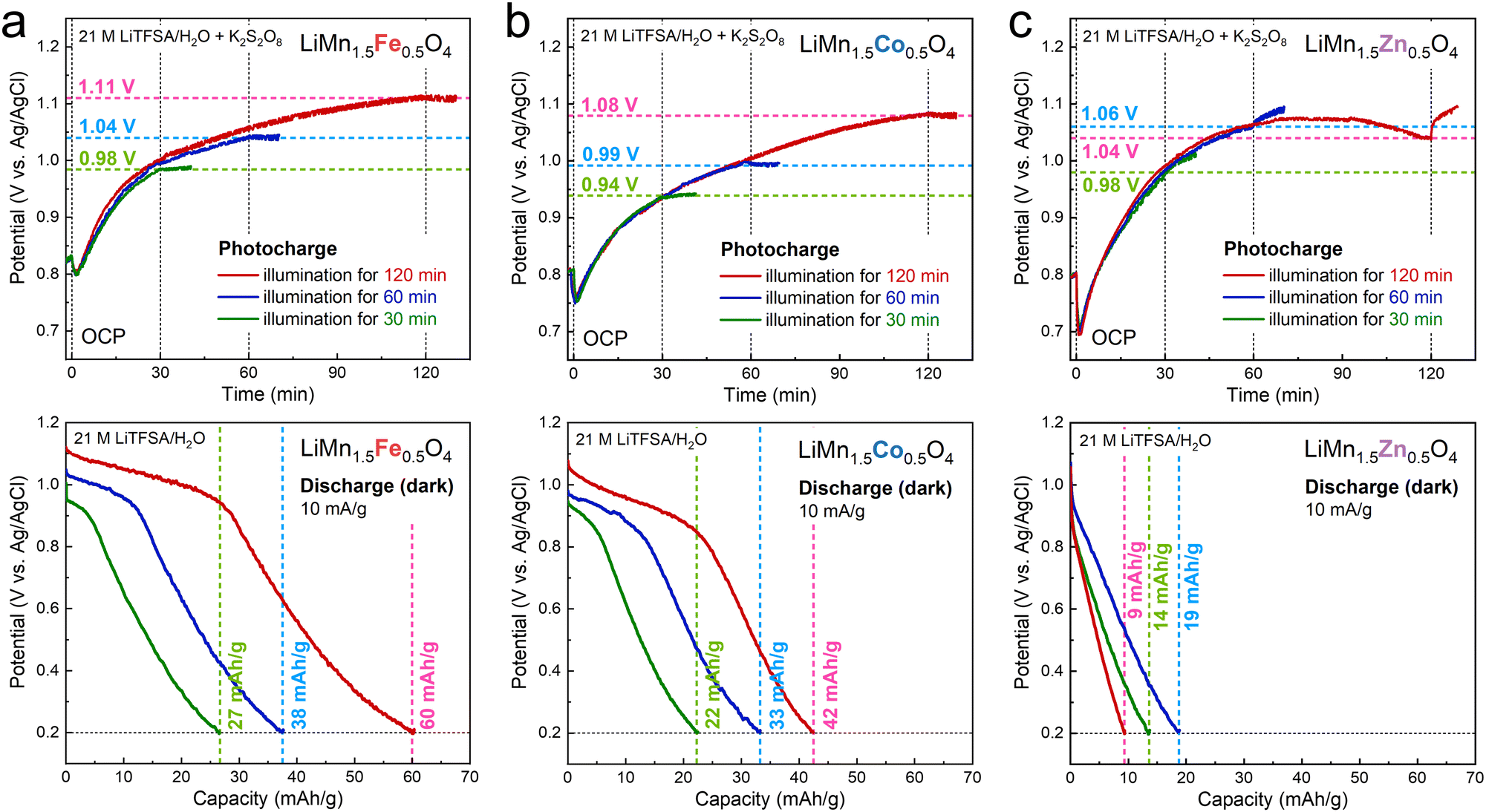 | ||
| Fig. 3 (a)–(c) Open circuit potential (OCP) during the photocharging process under illumination in 21 M LiTFSA/H2O with K2S2O8 as an electron acceptor (upper) and discharging profiles in the dark condition for the electrodes after photocharging (lower), where the electrolyte used in the discharging process was 21 M LiTFSA/H2O without K2S2O8. | ||
The obtained discharge capacities are displayed in Fig. 4 for comparison with those of reported LiMn2O4.17 In our previous work, we estimated the rate of photocharging in this system with TiO2 and K2S2O8, as shown by the grey line, where the slope (∼23 mA g−1) showed the photocharging rate based on ICP-OES.17 However, the discharge capacities after photocharging LiMn2O4 were much lower than the expected values, especially for the long-term photocharging. This is probably due to the relatively low stability of LixMn2O4 under illumination (Fig. 1), leading to some amount of irreversible capacity. In contrast, the discharge capacities of LiMn1.5Fe0.5O4 were in excellent agreement with those predicted by the grey line. In particular, they showed a linear relationship with the illumination time even for 120 min and were substantially higher than those for LiMn2O4. Since the theoretical capacity of LiMn1.5Fe0.5O4 is supposed to be lower than that of LiMn2O4 (Fig. 2(a)), the improved discharge capacity is surely evidence of enhanced stability under illumination.
 | ||
| Fig. 4 Discharge capacities of LiMn1.5M0.5O4 (M = Fe, Co) after the photocharging process together with our previous data for LiMn2O4.17 The grey line indicates the previously estimated photocharging rate in our photoelectrochemical system with TiO2 and K2S2O8.17 | ||
On the contrary, LiMn1.5Co0.5O4 exhibited a lower discharge capacity compared to that of LiMn2O4 after photocharging for 120 min. Given the improved stability of LiMn1.5Co0.5O4 under illumination (Fig. S11f, ESI†), there should be another factor for decreasing the efficiency of photocharging. Although this is still under investigation, a possible reason is the catalytic reaction of water oxidation; Co-based oxides are famous water oxidation catalysts,32 and they tend to provide holes to water compared to Fe-based oxides as demonstrated in combination with TiO2.33 The water-in-salt LiTFSA electrolyte has much higher stability against oxidation compared to that of dilute aqueous solutions owing to its unique solvation structure,21 and water oxidation was not suggested for LiMn1.5Fe0.5O4. Thus, Co is responsible for extra amounts of the oxidation reaction. As shown in Fig. S17 (ESI†), ex situ X-ray absorption near-edge structure (XANES) analysis also revealed little change in the valence state of Mn after photocharging LiMn1.5Co0.5O4. In contrast, an edge shift toward higher energy indicating Mn oxidation was clearly observed for LiMn1.5Fe0.5O4 (Fig. S18, ESI†).
In summary, we successfully demonstrated the feasibility of photocharging LiMn2O4-based spinel-oxide materials, which are compositionally modified to improve the stability. We compared photoelectrochemical properties of LiMn1.5M0.5O4 (M = Fe, Co, Ni, Zn) cathode materials and revealed that there are trade–off relationships between stability under illumination and capacity, depending on the amount of Mn3+ in the spinel-oxide materials. LiMn1.5Fe0.5O4 has a good balance of them and, consequently, exhibited discharge capacities substantially higher than those of LiMn2O4. One of the great advantages of spinel materials is their high designability in the structure.34,35 We hope that this work will provide fundamental guidelines for designing spinel-oxide cathode materials and promote the development of advanced PRBs.
This work was supported by JSPS KAKENHI (grant numbers 20K22460, 22K14499, 22H02265, 21H0164, 22KK0068) and by NIMS Joint Research Hub Program (QN3510). XRD analysis and SEM observation were carried out at the NIMS Battery Research Platform. We thank Dr F. Sakamoto for the technical help with ICP-OES at the Analytical Research Core for Advanced Materials, Institute for Materials Research, Tohoku University.
Conflicts of interest
There are no conflicts to declare.Notes and references
- A. D. Salunke, S. Chamola, A. Mathieson, B. D. Boruah, M. De Volder and S. Ahmad, ACS Appl. Energy Mater., 2022, 5, 7891–7912 CrossRef CAS.
- J. Lv, J. Xie, A. G. A. Mohamed, X. Zhang and Y. Wang, Chem. Soc. Rev., 2022, 51, 1511–1528 RSC.
- A. G. Hodes, J. Manassen and D. Cahen, Nature, 1976, 261, 403–404 CrossRef.
- O. Nguyen, E. Courtin, F. Sauvage, N. Krins, C. Sanchez and C. Laberty-Robert, J. Mater. Chem. A, 2017, 5, 5927–5933 RSC.
- A. Paolella, C. Faure, G. Bertoni, S. Marras, A. Guerfi, A. Darwiche, P. Hovington, B. Commarieu, Z. Wang and M. Prato, et al. , Nat. Commun., 2017, 8, 14643 CrossRef CAS PubMed.
- T. Nomiyama, K. Sasabe, K. Sakamoto and Y. Horie, Jpn. J. Appl. Phys., 2015, 54, 071101 CrossRef.
- W. Guo, X. Xue, S. Wang, C. Lin and Z. L. Wang, Nano Lett., 2012, 12, 2520–2523 CrossRef CAS PubMed.
- B.-M. Kim, M.-H. Lee, V. S. Dilimon, J. S. Kim, J. S. Nam, Y.-G. Cho, H. K. Noh, D.-H. Roh, T.-H. Kwon and H.-K. Song, Energy Environ. Sci., 2020, 13, 1473–1480 RSC.
- M.-H. Lee, B.-M. Kim, Y. Lee, H.-G. Han, M. Cho, T.-H. Kwon and H.-K. Song, ACS Energy Lett., 2021, 6, 1198–1204 CrossRef CAS.
- S. Ahmad, C. George, D. J. Beesley, J. J. Baumberg and M. De Volder, Nano Lett., 2018, 18, 1856–1862 CrossRef CAS PubMed.
- B. D. Boruah, A. Mathieson, B. Wen, S. Feldmann, W. M. Dose and M. De Volder, Energy Environ. Sci., 2020, 13, 2414–2421 RSC.
- B. D. Boruah and M. De Volder, J. Mater. Chem. A, 2021, 9, 23199–23205 RSC.
- X. Zhang, K. Su, A. G. A. Mohamed, C. Liu, Q. Sun, D. Yuan, Y. Wang, W. Xue and Y. Wang, Energy Environ. Sci., 2022, 15, 780–785 RSC.
- N. Tewari, S. B. Shivarudraiah and J. E. Halpert, Nano Lett., 2021, 21, 5578–5585 CrossRef CAS PubMed.
- H. Liu, P. Wu, R. Wang, H. Meng, Y. Zhang, W. Bao and J. Li, ACS Nano, 2023, 17, 1560–1569 CrossRef CAS PubMed.
- R. Zhang, Z. Chen, J. Ma, P. Zhang, M. Liu, X. Li, R. Zhao, J. Tang, Z. Ren and S. Li, Chem. Commun., 2023, 59, 2911–2914 RSC.
- K. Shimokawa, S. Matsubara, A. Okamoto and T. Ichitsubo, Chem. Commun., 2022, 58, 9634–9637 RSC.
- M. M. Thackeray, Prog. Solid State Chem., 1997, 25, 1–71 CrossRef CAS.
- A. Lee, M. Vörös, W. M. Dose, J. Niklas, O. Poluektov, R. D. Schaller, H. Iddir, V. A. Maroni, E. Lee, B. Ingram, L. A. Curtiss and C. S. Johnson, Nat. Commun., 2019, 10, 4946 CrossRef PubMed.
- J. Lipton, Y. Ma, J. A. Röhr, J. Zhu, H. Wang, S. A. Maclean, C. S. Johnson and A. D. Taylor, Cell Rep. Phys. Sci., 2022, 3, 101051 CrossRef CAS.
- L. Suo, O. Borodin, T. Gao, M. Olguin, J. Ho, X. Fan, C. Luo, C. Wang and K. Xu, Science, 2015, 350, 938–943 CrossRef CAS PubMed.
- L. Guohua, H. Ikuta, T. Uchida and M. Wakihara, J. Electrochem. Soc., 1996, 143, 178–182 CrossRef.
- R. Bittihn, R. Herr and D. Hoge, J. Power Sources, 1993, 43, 223–231 CrossRef CAS.
- R. J. Gummow, A. De Kock and M. M. Thackeray, Solid State Ionics, 1994, 69, 59–67 CrossRef CAS.
- T. Ohzuku, S. Takeda and M. Iwanaga, J. Power Sources, 1999, 81–82, 90–94 CrossRef CAS.
- A. Varma, A. S. Mukasyan, A. S. Rogachev and K. V. Manukyan, Chem. Rev., 2016, 116, 14493–14586 CrossRef CAS PubMed.
- K. Shimokawa, T. Atsumi, M. Harada, R. E. Ward, M. Nakayama, Y. Kumagai, F. Oba, N. L. Okamoto, K. Kanamura and T. Ichitsubo, J. Mater. Chem. A, 2019, 7, 12225–12235 RSC.
- K. Shimokawa, T. Atsumi, N. L. Okamoto, T. Kawaguchi, S. Imashuku, K. Wagatsuma, M. Nakayama, K. Kanamura and T. Ichitsubo, Adv. Mater., 2021, 33, 2007539 CrossRef CAS PubMed.
- W. Miran, W. Huang, X. Long, G. Imamura and A. Okamoto, Patterns, 2022, 3, 100637 CrossRef CAS PubMed.
- Y. Ein-Eli, W. Wen and S. Mukerjee, Electrochem. Solid-State Lett., 2005, 8, A141–A144 CrossRef CAS.
- M. Kunduraciz and G. G. Amatucci, J. Electrochem. Soc., 2006, 153, A1345–A1352 CrossRef.
- X. Deng and H. Tüysüz, ACS Catal., 2014, 4, 3701–3714 CrossRef CAS.
- M. Okazaki, Y. Wang, T. Yokoi and K. Maeda, J. Phys. Chem. C, 2019, 123, 10429–10434 CrossRef CAS.
- K. Shimokawa, T. Hatakeyama, H. Li and T. Ichitsubo, Curr. Opin. Electrochem., 2023, 38, 101209 CrossRef CAS.
- K. Shimokawa and T. Ichitsubo, Curr. Opin. Electrochem., 2020, 21, 93–99 CrossRef CAS.
Footnote |
| † Electronic supplementary information (ESI) available. See DOI: https://doi.org/10.1039/d3cc01902k |
| This journal is © The Royal Society of Chemistry 2023 |