DOI:
10.1039/D2YA00143H
(Paper)
Energy Adv., 2022,
1, 613-622
A high performance piezoelectric–triboelectric hybrid energy harvester by synergistic design†
Received
13th June 2022
, Accepted 19th July 2022
First published on 20th July 2022
Abstract
Generation of electricity from naturally abandoned mechanical vibrations is of utmost importance in the modern era of the internet of things. This strategy is highly beneficial to drive low power electronic devices and useful to numerous sensor applications, which include stress/strain sensing, tissue regeneration, environmental remediation, etc. Piezoelectrics are the preferred choice as mechanical energy harvesters and for related applications. Ferroelectric ceramics with the general formula ABO3 are the primary choice of piezoelectrics for these applications. Such systems show a high piezoelectric coefficient (d33) owing to collaborative interactions of the inherent polarization vectors of the crystal lattices. Here, we have invoked the idea of grain size-assisted polarization enhancement for improved piezoelectric energy harvesting (PEH) performance of BaTiO3 in the form of a polymer/ceramic composite. This composite also exhibits improved triboelectric energy harvesting (TEH) performance owing to the high dielectric constant of the ceramics. Grain size has a dramatic effect on the dielectric constant along with influencing d33. Here we demonstrate how the performance of a hybrid device relying on the PEH and TEH processes can be improved by grain size variation. Our approach shows a new way to improve the performance of hybrid mechanical energy harvesting devices.
Introduction
Every day we come across numerous mechanical motions/vibrations. Examples include human/animal body movement, rain/water motion, motion of electrical vehicles, wind flow, and vibrations of parts of instruments in operation. Scavenging electrical energy from such naturally abandoned mechanical vibrations is of utmost importance in the present era of renewable energy generation. Converting mechanical energy to electrical energy has multiple benefits. These include potential replacement of batteries for low power electronic devices operating at remote locations,1,2 stress/strain sensors for probing device functionality,3,4 tissue regeneration,5 environmental remediation,6etc. Two widely studied methods to harvest mechanical motions are triboelectric energy harvesting (TEH)7–10 and piezoelectric energy harvesting (PEH).11–15 The TEH process relies on the contact/separation or friction between different material layers with dissimilar work functions. On the other hand, the PEH process is governed by the principle of piezoelectricity, i.e., generation of electrical charges on the opposite surfaces of the non-centrosymmetric crystals upon applications of mechanical vibrations.16 The PEH process, when it gets combined with the TEH process, becomes hybrid energy harvesting.17–19 Materials and device architectures are important parameters to influence the energy harvesting performances in this case. Flexible composite-based devices are receiving increasing attention in this regard. It brings device compatibility to the applications and large strain/strain sustainability, and overcomes the limit of the brittleness of the piezoelectric ceramics. Different types of polymer/ceramic composite devices were fabricated and tested for mechanical energy harvesting and applications.20,21 Research is ongoing to design 0–3, 1–3 and 3–3 type polymer/ceramic devices.22–25 Among them, 0–3 type devices are most widely investigated owing to the ease of fabrication besides the benefit of device flexibility and large stress/strain sustainability.
Material systems play the most important role in the PEH, TEH and hybrid device performances. Ferroelectric ceramics with the general formula ABO3 are the preferred choice for piezoelectric energy harvesters. This is owing to the very fact that ferroelectrics exhibit large stress induced charge co-efficient (d33).26–28 Enhanced polar structure ordering, co-existence of multi-structural symmetries and/or enhanced domain reorientation in the piezoceramics lead to high piezoelectric properties.26,29,30 All such structure/microstructural features inherent to the ferroelectrics depend on the grain size of the ceramics.30,31 Increased grain size enables enhanced polar structural strength responsible for enhanced piezoelectricity. Grain size-assisted enhanced piezoelectricity is sustained when ceramics are incorporated into polymer matrices, i.e. when they form polymer ceramic composites.32,33 Naturally, PEH devices based on the large (optimum) grain ferroelectrics will exhibit enhanced energy harvesting performance and due to their high performances, such devices are suitable for specific sensor applications.
Besides high piezoelectric co-efficient, ferroelectrics also exhibit high dielectric constant. Several ferroelectric ceramics show dielectric constants >10![[thin space (1/6-em)]](https://www.rsc.org/images/entities/char_2009.gif) 000 while exhibiting d33 > 300 pC N−1 at room temperature.34,35 Such high permittivity ceramics, once they form a composite with a polymer, are highly advantageous for the devices.36,37 Composites containing high permittivity ceramics produce high internal polarization under the electric field generated from the contact-separation between triboelectric layers. Strong internal polarization induces enhanced charge density at the bottom electrode oftheTEH device.37 Interestingly, grain size plays an important role in the dielectric properties of ferroelectric ceramics. Polar structural correlation in ceramics is dependent on the grain size, which plays a crucial role in the inherent internal polarization.30,31 Such grain size optimized high permittivity ceramics, when they form a composite, exhibit high energy harvesting performance of TEH devices. Naturally, a hybrid device which operates based on the coupling of piezoelectric and triboelectric mechanisms can show high energy output when fabricated with grain size optimized ceramics and polymer composites. Thus, one can obtain a high performance hybrid device by single parameter namely, grain size tuning. This simple yet effective concept is demonstrated in the present manuscript. Dielectric piezoceramic BaTiO3 (BT) is chosen as a model system as this system is well explored in terms of its structure, grain size dependent piezoelectric–ferroelectric properties, and piezoelectric–triboelectric energy harvesting applications. Different BT particles with varying d33 and dielectric constant are embedded in the polydimethylsiloxane (PDMS) matrix. PEH and hybrid devices are fabricated and their performances are studied.
000 while exhibiting d33 > 300 pC N−1 at room temperature.34,35 Such high permittivity ceramics, once they form a composite with a polymer, are highly advantageous for the devices.36,37 Composites containing high permittivity ceramics produce high internal polarization under the electric field generated from the contact-separation between triboelectric layers. Strong internal polarization induces enhanced charge density at the bottom electrode oftheTEH device.37 Interestingly, grain size plays an important role in the dielectric properties of ferroelectric ceramics. Polar structural correlation in ceramics is dependent on the grain size, which plays a crucial role in the inherent internal polarization.30,31 Such grain size optimized high permittivity ceramics, when they form a composite, exhibit high energy harvesting performance of TEH devices. Naturally, a hybrid device which operates based on the coupling of piezoelectric and triboelectric mechanisms can show high energy output when fabricated with grain size optimized ceramics and polymer composites. Thus, one can obtain a high performance hybrid device by single parameter namely, grain size tuning. This simple yet effective concept is demonstrated in the present manuscript. Dielectric piezoceramic BaTiO3 (BT) is chosen as a model system as this system is well explored in terms of its structure, grain size dependent piezoelectric–ferroelectric properties, and piezoelectric–triboelectric energy harvesting applications. Different BT particles with varying d33 and dielectric constant are embedded in the polydimethylsiloxane (PDMS) matrix. PEH and hybrid devices are fabricated and their performances are studied.
Experimental
Synthesis of the ferroelectric ceramic
Perovskite oxide ceramic BaTiO3 was prepared by a conventional solid-state synthesis process. Stoichiometric amounts of high purity chemicals BaCO3 (Alpha aesar, 99% purity) and TiO2 (Alpha aesar, 99.9% purity) are mixed thoroughly by a plenary ball mill (Fritsch) using acetone medium for 6 h. Mixed powders are calcined at 1100 °C for 4 h. Ceramic disks are made by uniaxial pressure of 200 MPa out of the homogeneous mixture of calcined powder and polyvinyl alcohol (PVA). Sintering of pellets was carried out at 1500 °C for 3 h. Two types of specimens were used for device fabrication and related characterizations – the calcined powder (termed as BT-cal) and the ground and annealed (at 700 °C for 2 h) powder derived from sintered pellets (designated as BT-1500).
Composite device fabrication
A 0–3 type polymer/ceramic composite was prepared using the BT-cal and BT-1500 powders, respectively. The BT ceramic and PDMS (average molecular weight 3800) composite was fabricated by the tape casting (MTI instrument) method. The weight percentage of the ceramic was 20% for all the specimens as this is reported to be the optimum weight fraction for a 0–3 type composite.24 A homogeneous mixture of ceramic powder and PDMS solution is coated on the aluminium foils and further cured at 80 °C. Composite films with a thickness of 245 μm were obtained. Flexible PEH (FPEH) devices with composite dimensions 1.5 cm × 1.5 cm were prepared with a bottom electrode of aluminium and a top electrode with gold sputtered (1.2 cm × 1.2 cm). The device was packed with PDMS polymer. The TEH device (hybrid device) was fabricated after removing aluminium foil from the film. Subsequently, the naked composite film was placed on the top of the aluminium electrode of a TEH layer. The same aluminium layer was used as the opposite layer of the hybrid device. Hybrid device preparation steps can be found elsewhere.18 A PDMS-5 wt% carbon mixture was prepared for structural health monitoring applications. Two FPEH devices were embedded in the PDMS/carbon composite during its curing process. The mechanical impact was applied at the central part (∼10 mm diameter region) of the PDMS/carbon composite sheet.
Physical characterizations
Structure and property measurements were carried out on the ceramic specimens and on the composites. X-ray powder diffraction (XRPD) was measured on the ground and annealed powder using a Pan Analytical diffractometer with Cu Kα1 radiation. The local structural study was carried out by Raman spectroscopy measurement using a LabRAM spectrometer (wavelength 514 nm, and laser power 10 mW) on the powder specimens. Global structural analysis was carried out by Rietveld refinement on the XRPD patterns. Ferroelectric hysteresis and leakage current measurements were carried out on the pellets/composites using a ferroelectric tester (Radiant Technology). DC electrical poling was carried out on the silver electrode coated pellets at 50 kV cm−1 for 1 h. Poling of the composites was carried out at 150 kV cm−1 for 1 h. The piezoelectric coefficient (d33) was measured on the poled pellets/composites using an APS International d33 meter (model no YE2730A). Room temperature dielectric measurements on the ceramics and composites were performed using the HOIKI LCR meter (HIOKI IM 3570). A piezoresponse force microscopy instrument (PFM, Multimode 8, Bruker) was used to investigate the ferroelectric domains, transverse piezoelectric coefficient, and domain switching on the BT-1500 pellet. This instrument was coupled with a high voltage precision amplifier (TEGMA-2350) for applying a higher tip bias voltage to examine the switching behavior. In the out of plane measurement, one end of the sample was connected to the grounded metal substrate with Ag paste and the other end was connected to the conductive tip. The electric field is created by applying a voltage between the tip and a grounded metal substrate through the sample surface. The sample drive voltage of 5 V was applied to the specimen to acquire the topography, high speed-piezoresponse (HS-PR) amplitude, and HS-PR phase signal images. Voltage swiping was carried out for ferroelectric and piezoelectric hysteresis measurement. Scanning electron microstructures on the ceramic powder, sintered and polished surface and composite were collected using a field emission-scanning electron microscope (TESCAN MIRA3). Grain size was calculated using image J software. The electrical responses of the FPEH and TENG devices were measured using an electrometer (model 6514; Keithley) and current preamplifier (Stanford Systems). A constant periodic mechanical force (5N) was applied using a LinMot motor (model HF01-37).
Results and discussion
Microstructure, structure and electrical properties of piezoceramics
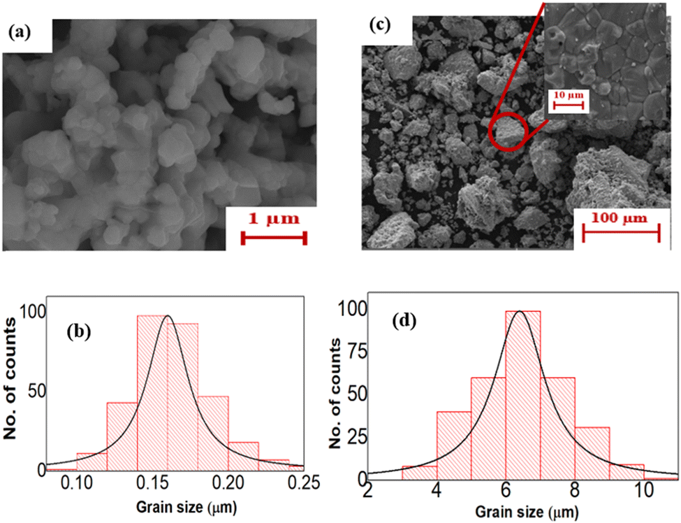
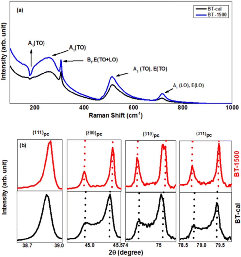
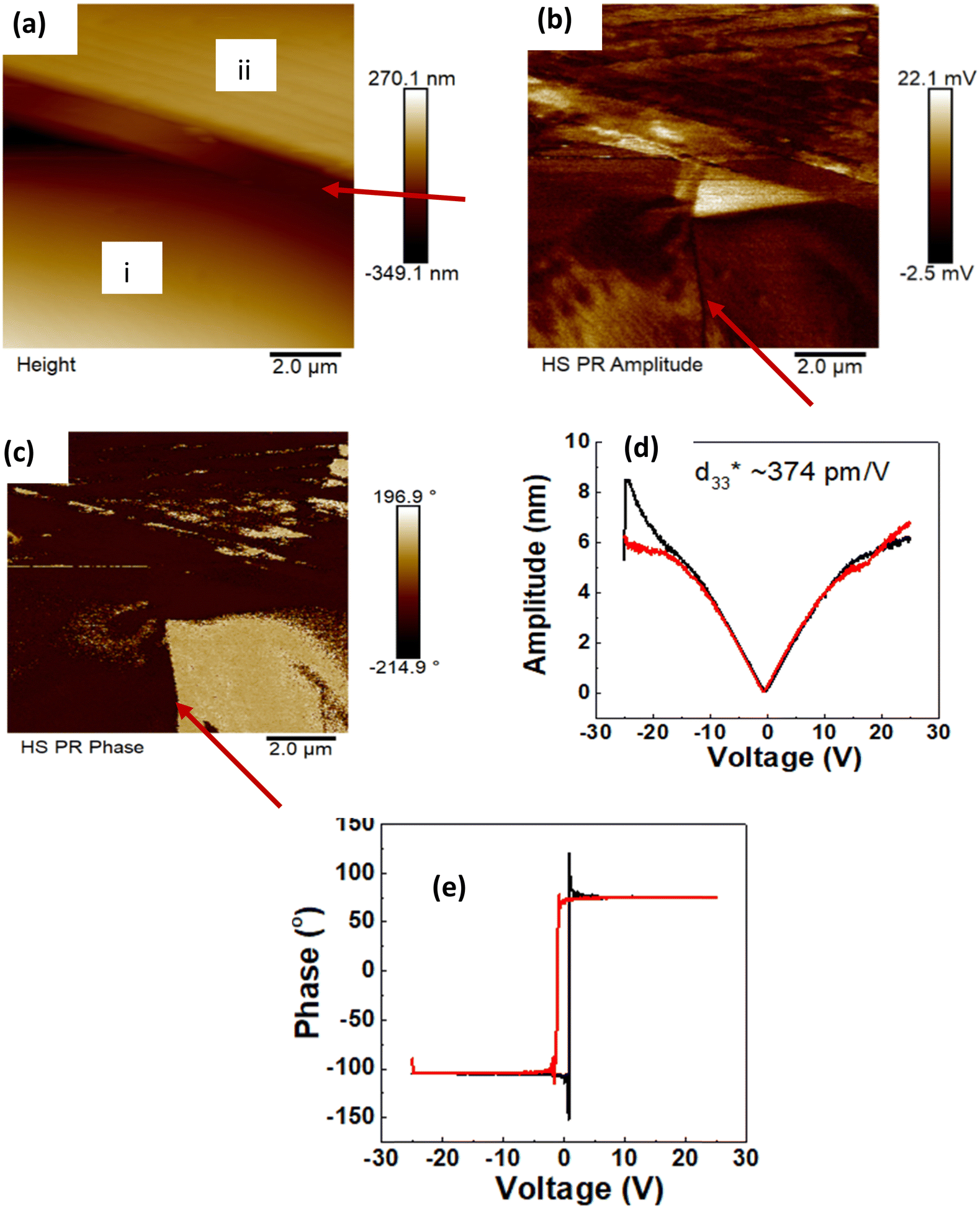
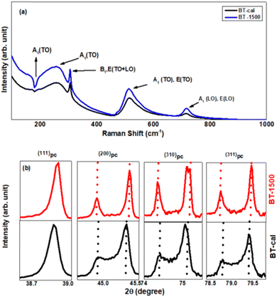
Fig. 1(a) shows SEM micrographs of the BT-cal specimen. The average grain size of this specimen is found to be ∼0.16 μm shown in the histogram, Fig. 1(b). The powder specimen of BT-1500 shows clustering of the grains with a range of size distribution, Fig. 1(c). However, smaller clusters have size ∼10 μm and the average grain size of the BT-1500 ceramic is ∼6.4 μm (Fig. 1(d)), thereby suggesting that the average grain size of the sintered specimen did not change after grinding. Further characterizations were carried out on the specimens with these grain sizes. Fig. 2(a) shows how the Raman spectra for the BT specimens with different modes are assigned. The sharp peak at ∼306 cm−1 (B1, E modes) and a weak and broad peak at ∼717 cm−1 (A1, E modes) signify the tetragonal local structure for both the specimens.38,39 It is interesting to note that the dip at ∼180 cm−1 arises due to the coupling of different A1 modes.38,40 For the submicron grain size specimen (BT-cal), sufficient reduction in the dip indicates a weakening of the tetragonality (ferroelectric strength) in the specimen as compared to that in BT-1500. Fig. 2(b) shows the selected Bragg peaks of the XRPD patterns of the BT-1500 and BT-cal specimens, respectively. The singlet nature of the {111}pc peak and doublet nature of the {200}pc peak signify the tetragonal global structure of the specimens. It is interesting to note the nature in the {200}pc Bragg peak splitting of the specimens. This is highlighted with the vertical dotted lines in Fig. 2(b). The 2θ separation between the {002}pc and {200}pc peaks for BT-1500 is 0.51° while that for BT-cal is 0.44°. The reduced peak splitting suggests weakening in the polar structural ordering and hence weakening in the ferroelectric properties with grain size reduction. This is further clarified from the structure refinement for the specimens. As shown in the Fig. S1a (ESI†), the XRPD pattern of BT-1500 can be well accounted with the tetragonal P4mm model. On the other hand, the BT-cal specimen shows a combination of P4mm and cubic Pm![[3 with combining macron]](https://www.rsc.org/images/entities/char_0033_0304.gif) m phase coexistence, Fig. S1b (ESI†). The cubic phase signifies the non-polar non ferroelectric nature of the submicron particles. Tables S1 and S2 (ESI†) show the refinement results. It is further evidenced from the tables that the tetragonality (c/a ratio) for BT-cal is 1.008 and that for BT-1500 is 1.01. Consistent with the Raman and XRPD analysis, it can be inferred that with size reduction, polar structural co-relation reduces. Fig. 3(a) shows well saturated bipolar P–E loops for BT-1500 with Pmax ∼ 15 μC cm−2 and it shows d33 ∼ 140 pC N−1. It also exhibits a high dielectric constant and low leakage current shown in Fig. 3(b) and (c), respectively. Apart from property measurement on a large scale, we obtained microstructure, and property measurement for BT1500 on the local scale using PFM as shown in Fig. 4. Fig. 4(a) shows the grain morphology and grain boundary shown with the arrow. As it is evident from the figure, there is a surface roughness in between the grain and grain boundary region. Lower height in the grain boundary is visible on the scale bar. However, within a grain (grain i for example), a 180° domain is confirmed from the amplitude and phase mapping, Fig. 4(b) and (c), respectively. The domain wall region is highlighted with an arrow in Fig. 4(b) and (c), respectively. A strain vs field (amplitude vs voltage) sweep was carried out on the specimen subjected to external bias field, Fig. 4(d). Transverse piezoelectric coefficient (d33*) ∼ 374 pm V−1 is obtained from the slope of the amplitude–voltage curve. 180° phase sweeping (Fig. 4(e)) with change of voltage polarity is a typical characteristic of a ferroelectric phase. These local structural measurements confirm the ferroelectric/piezoelectric character of the specimen. The values of ferroelectric polarization, piezoelectric coefficient and dielectric constant obtained for the large grain BT-1500 specimen are consistent with the literature.30,41 Following earlier reports,30,41 small grain sized specimen BT-cal is expected to exhibit inferior properties. Since, the aforementioned properties were measured on the dense pellets, we are unable to measure them for BT-cal due to the lack of a dense pellet of it with the grain size unaltered. However, as structural analysis confirms reduction in the ferroelectric strength, BT-cal is expected to show reduced properties as compared to that of BT-1500.
m phase coexistence, Fig. S1b (ESI†). The cubic phase signifies the non-polar non ferroelectric nature of the submicron particles. Tables S1 and S2 (ESI†) show the refinement results. It is further evidenced from the tables that the tetragonality (c/a ratio) for BT-cal is 1.008 and that for BT-1500 is 1.01. Consistent with the Raman and XRPD analysis, it can be inferred that with size reduction, polar structural co-relation reduces. Fig. 3(a) shows well saturated bipolar P–E loops for BT-1500 with Pmax ∼ 15 μC cm−2 and it shows d33 ∼ 140 pC N−1. It also exhibits a high dielectric constant and low leakage current shown in Fig. 3(b) and (c), respectively. Apart from property measurement on a large scale, we obtained microstructure, and property measurement for BT1500 on the local scale using PFM as shown in Fig. 4. Fig. 4(a) shows the grain morphology and grain boundary shown with the arrow. As it is evident from the figure, there is a surface roughness in between the grain and grain boundary region. Lower height in the grain boundary is visible on the scale bar. However, within a grain (grain i for example), a 180° domain is confirmed from the amplitude and phase mapping, Fig. 4(b) and (c), respectively. The domain wall region is highlighted with an arrow in Fig. 4(b) and (c), respectively. A strain vs field (amplitude vs voltage) sweep was carried out on the specimen subjected to external bias field, Fig. 4(d). Transverse piezoelectric coefficient (d33*) ∼ 374 pm V−1 is obtained from the slope of the amplitude–voltage curve. 180° phase sweeping (Fig. 4(e)) with change of voltage polarity is a typical characteristic of a ferroelectric phase. These local structural measurements confirm the ferroelectric/piezoelectric character of the specimen. The values of ferroelectric polarization, piezoelectric coefficient and dielectric constant obtained for the large grain BT-1500 specimen are consistent with the literature.30,41 Following earlier reports,30,41 small grain sized specimen BT-cal is expected to exhibit inferior properties. Since, the aforementioned properties were measured on the dense pellets, we are unable to measure them for BT-cal due to the lack of a dense pellet of it with the grain size unaltered. However, as structural analysis confirms reduction in the ferroelectric strength, BT-cal is expected to show reduced properties as compared to that of BT-1500.
 |
| | Fig. 1 (a) Scanning electron microscopy (SEM) micrograph of a calcined powder of BaTiO3 (BT-cal). (b) The corresponding grain size distribution is shown in the histogram. (c) SEM micrograph of the crushed and annealed powder of the sintered specimen of BaTiO3 (BT-1500) showing clustering of the grains with varying size. The inset shows the actual grainy contrast of the sintered pellet. (d) The grain size distribution of the sintered pellet is shown in the histogram. | |
 |
| | Fig. 2 (a) Comparative Raman spectra for different BaTiO3 specimens (BT-1500 and BT-cal respectively). Each vibrational mode is indicated by the arrows. (b) X-Ray powder diffraction (XRPD) Bragg profiles of different BaTiO3 specimens. Dotted lines indicate polar structural distortion for the specimens. Each pair of Bragg peaks is plotted for the same 2θ interval. | |
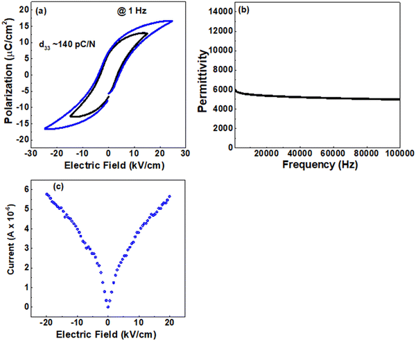 |
| | Fig. 3 (a) Bipolar polarization (P) – electric field (E) hysteresis curve for the BT-1500 pellet. (b) Dielectric permittivity (ε′) of the BT-1500 pellet specimen. (c) Leakage current (I) vs. electric field (E) of BT-1500. | |
 |
| | Fig. 4 Piezoresponse Force Microscopy (PFM) studies on the BT-1500 pellet – (a) Surface topography, where the arrow indicates the grain boundary region; parts of two grains are indicated with numbers. (b) and (c) PFM amplitude and phase images at zero bias voltage, where arrows indicate the domain wall boundary; (d) and (e) PFM amplitude and phase under different bias voltage. Converse piezoelectric coefficient (d33*) determined from the slope at the linear region in (d). | |
Microstructure, structure and electrical properties of the composite
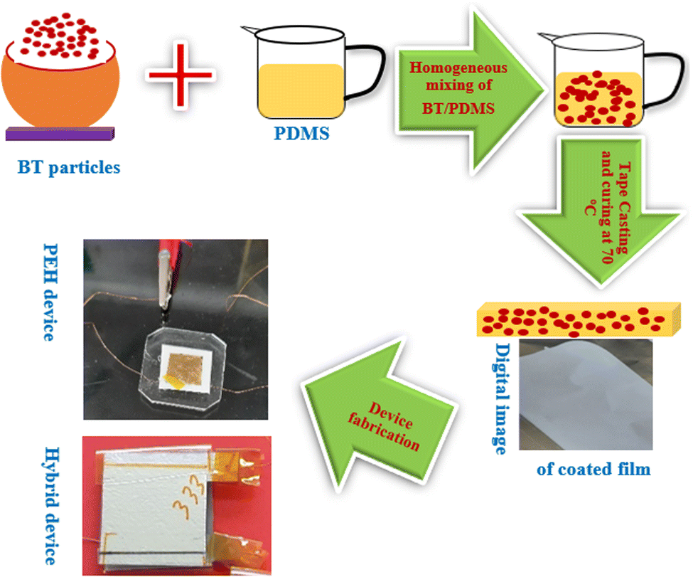
Next, we studied the structure and electrical properties of BT/polymer composite specimens. A 0–3 type composite was prepared by mixing powder specimens of BT in the PDMS polymer. The film processing steps are shown in Fig. 5. The mixture of ceramic particles in PDMS is schematically shown in Fig. 5. A picture of a tape coater and composite film coated on the Al foil is shown in the figure. An SEM micrograph of the composite shows the presence of ceramic particles/clusters in the polymer matrix (not shown in the figure). Consistent with the microstructures, the XRD patterns on the film show the formation of a ceramic/polymer composite, Fig. 6(a). As shown in the figure, a broad hump in between 10° to 20° present for all specimens is characteristic of the polymer phase. Additionally, peaks corresponding to the perovskite BT specimens are present. Careful observation of the Bragg peaks shows that the composite consisting of BT-cal has reduced polar structural strength as compared to that consisting of BT-1500 particles. Polarization (P) vs. electric field (E) curves (Fig. 6(b)) show the ferroelectric nature of the composite due to the presence of ferroelectric ceramic particles inside non-ferroelectric PDMS. The composite exhibits much reduced polarization as compared to that of the bulk ceramic due to the presence of a large fraction of inactive polymer in it. However, among the composites, BT-1500/PDMS shows higher remnant polarization as compared to that of BT-cal/PDMS suggesting that the composite with larger grains has superior ferroelectric properties. Consistent with that, the composite with larger grains showed d33 ∼ 6 pC N−1, while that with smaller grains shows d33 ∼ 2 pC N−1. Room temperature dielectric measurement on the composite (Fig. 6(c)) shows that the relative permittivity increases from that of pure PDMS to that of the BT-1500/PDMS composite. The enhanced dielectric property for the larger grain specimen in the composite is attributed to the enhanced polarization strength of the ceramic. Structure property measurement on the composite suggests that the BT-cal/PDMS composite has reduced piezoelectric, ferroelectric and dielectric properties as compared to that of the BT-1500/PDMS composite. We have further studied the device performances with these composites.
 |
| | Fig. 5 Processing steps of the BaTiO3 piezoceramic/PDMS composite and PEH/hybrid (PEH + TEH) device fabrication. | |
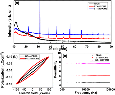 |
| | Fig. 6 (a) XRPD on the surface of the BaTiO3 piezoceramics/PDMS composite showing the signature of the polymer (broad hump) and ceramic particle present in the film. (b) P–E hysteresis loops for the composites. (c) Dielectric permittivity (ε′) of the composite specimens as a function of frequency. | |
Mechanical energy harvesting and sensing behavior of the composite devices
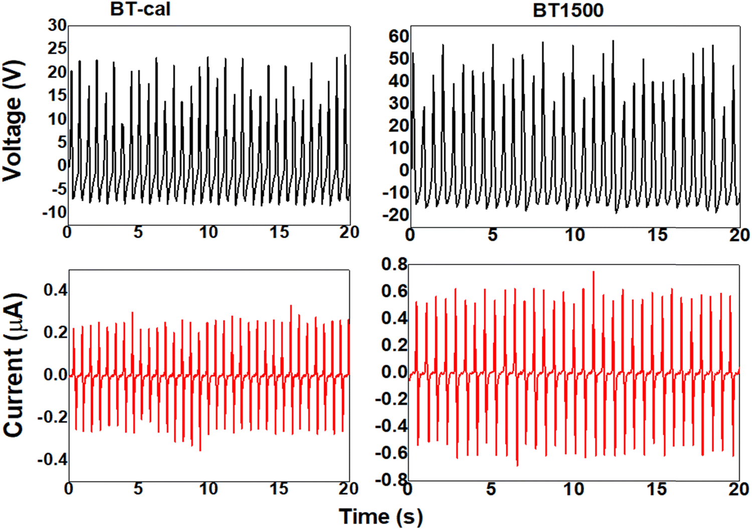
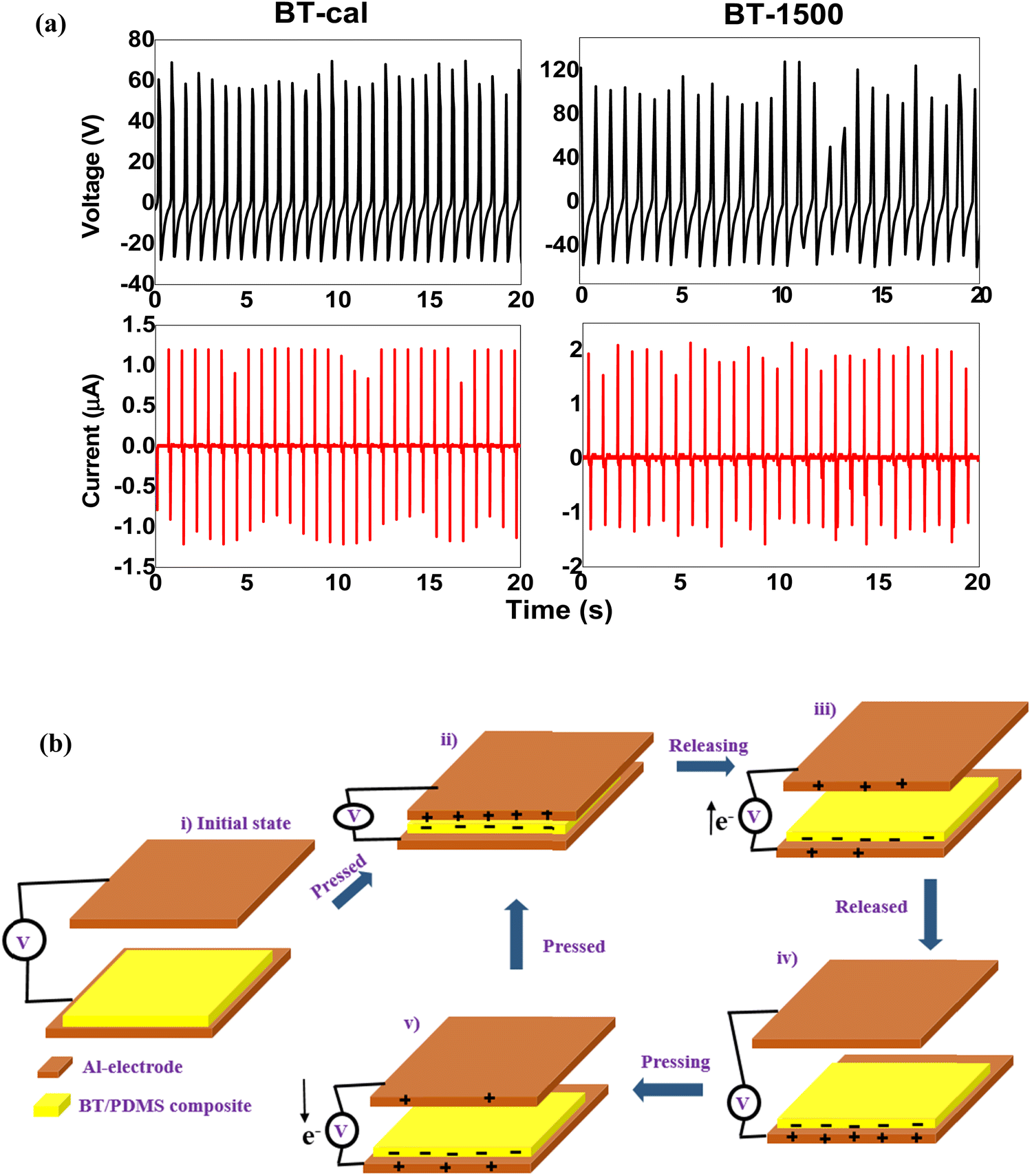
Mechanical energy harvesting performance of the devices was carried out in two different ways. First, the performance of the piezoelectric energy harvesting (PEH) device is determined. Then, the performance of the hybrid device (PEH + TENG) is evaluated. All the measurements were carried out under a periodic mechanical loading of 5 N and impact acceleration of 4 m s−2. The final electrical output data was collected after hitting the devices at least for 500 cycles. The top panel of Fig. 7 shows the measured open circuit voltage (VOC) of the BT-cal/PDMS and BT-1500/PDMS based PEH devices, respectively. As evidenced from the figure, the voltage output changes from ∼20 V (positive part) in the case of the BT-cal/PDMS composite to ∼50 V for the BT-1500/PDMS composite. Consistent with the scavenged voltage, the bottom panel of Fig. 7 shows that the output current (ISC) is increased from ∼0.2 μA (BT-cal/PDMS) to ∼0.6 μA (BT-1500/PDMS). Generation of the positive part of the voltage/current occurs due to the creation of a piezoelectric field arising from the change in the spontaneous polarization under the applied force. On the other hand, a negative peak arises due to the destruction of the piezoelectric field upon force removal. This mechanism of power generation for the PEH device is schematically shown in Fig. S2 (ESI†). Overall, the scavenged electrical power density is increased from ∼27.78 mW m−2 to ∼208.33 mW m−2. The increased harvested power density is attributed to the enhanced piezoelectric strength of the ferroelectric ceramic with larger grains. The performance of the hybrid device working based on piezoelectric and triboelectric principles is shown in Fig. 8(a). The working mechanism of a contact-separation mode TEH device is shown in Fig. 8(b). The performance of each hybrid device increases in comparison to their respective piezoelectric device counterpart. For instance, the output voltage of the PEH device consisting of the BT-cal/PDMS composite was ∼20 V. Now, the corresponding hybrid device consisting of the same composite exhibits an output voltage of ∼60 V. Similarly, the output current also increases in the hybrid device. This is due to the fact that the hybrid device has both the contributions – the piezoelectric part and triboelectric part arise from the contact separation between the composite and opposite metal layer.17–19 The output performance of the hybrid device consisting of BT-1500/PDMS is much improved as compared to that of the BT-cal/PDMS based hybrid device, Fig. 8(a). The VOC of the two devices is ∼60 V and ∼100 V, respectively, and the ISC of them is ∼1.25 μA and ∼2 μA, respectively. The scavenged power densities of the two devices are ∼0.33 W m−2 and ∼0.89 W m−2, respectively. The enhanced scavenged power density of the hybrid device composed of BT-1500/PDMS is attributed to the synergistic effects of the grain size-induced enhanced piezoelectric strength and dielectric constant of the BT-1500 ceramic. Enhancing the dielectric constant helps to increase the charge trapping in the dielectric layer, which arises from the contact-separation process.36,37 The dielectric strength helps to increase the triboelectric performance. Together, the enhanced piezoelectric and triboelectric energy harvesting synergistically improves the performance of the hybrid device. A literature summary of different strategies of active layer preparation and hybrid device performance is shown in Table S3 (ESI†). As one can find from the table, our concept is of very fundamental nature and it can be implemented along with other strategies. Together, the device performance is expected to enhance manifold. For example, a report shows (ref. 5 in Table S3, ESI†) active layer preparation by polymer, ceramic and conducting filler additions. If our idea of a grain size optimized ceramic is utilized in their strategy, the device performance will increase further. An active layer with polymer/grain size optimized ceramics/conducting filler and surface micropatterning (roughness) (such as ref. 4 in Table S3, ESI†) will improve the device performance further.
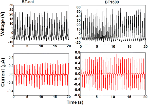 |
| | Fig. 7 Mechanical energy harvesting performance of the BT-cal/PDMS and BT1500/PDMS composite-based PEH devices under the periodic mechanical load of 5 N. Top panel shows the scavenged open circuit voltage (Voc) and bottom panel shows the scavenged short circuit current (Isc) for the devices. | |
 |
| | Fig. 8 (a) Mechanical energy harvesting performance of BT-cal/PDMS and BT1500/PDMS composite based hybrid (PEH + TEH) devices under the periodic mechanical load of 5 N. Top panel shows the scavenged open circuit voltage (Voc) and bottom panel shows the scavenged short circuit current (Isc) for the devices. Inset shows the real hybrid device. (b) Schematic working mechanism of the TEH device. | |
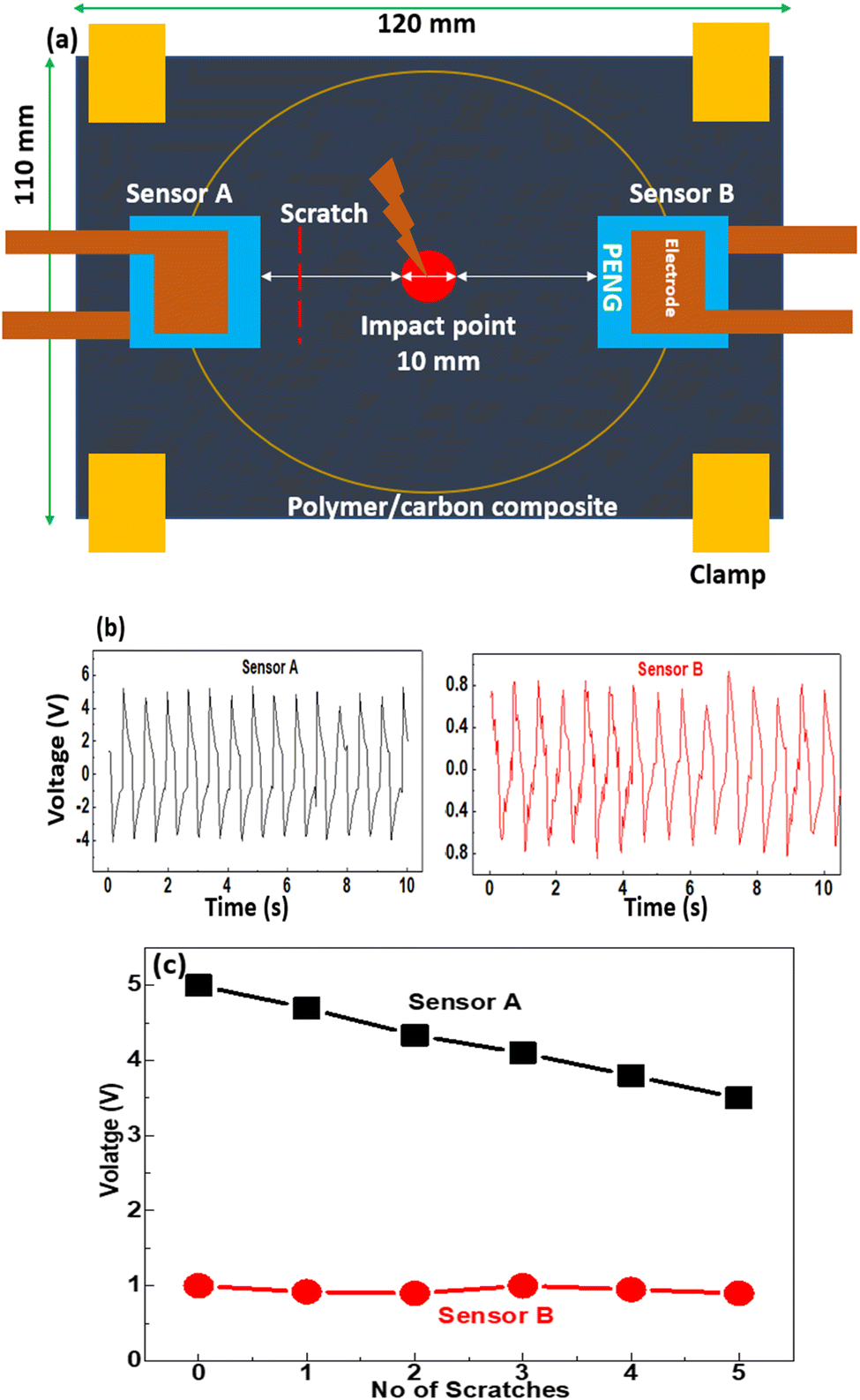
As a sensor application, we utilized flexible PEH (FPEH) devices to demonstrate structural health monitoring applications. Recently, such FPEH devices have been found to be promising for structural health monitoring of polymer–matrix composites (PMCs).42–46 PMCs are the preferred choice for widespread industrial applications owing to their high specific strength, good stiffness, and lightweight. However, such composites are subjected to a wide spectrum of loading during in-service use. Dynamic loading causes subsurface cracks and delamination in the composites. Therefore, it is important to diagnose the in-operando damage in the composite for safe operation. Several non-destructive testing methods are utilized for this purpose, which include optical fiber sensing, piezoresistive sensing, ultrasonic examination, etc.44 However, all these techniques have several demerits as well, which include complex installation process, brittleness of the optical fibers, etc. FPEHs can overcome these limitations. Additionally, these devices do not need an additional power supply for operation. All sorts of mechanical vibrations the PMCs experience while in use are the sources for electrical power generation in FPEHs. Any microstructural change in the subsurface of the composites modifies the vibration propagation from the impact point to the embedded FPEH devices. This in turn leads to a change in the scavenged electrical output. Change in the electrical output of the device subjected to mechanical deformation of the composite is the basic principle of structural health monitoring. Here we have used BT-1500/PDMS FPEH devices to carry out damage detection in the polymer composite. A schematic of the experimental arrangement is shown in Fig. 9(a). Two FPEH devices are inserted into the PDMS/carbon composite during its curing process. The devices are kept at equal distances from the center. A periodic force of 5 N was applied at the central part. While a periodic force is operating, we created mechanical scratches in the PDMS/carbon composite with an increasing number near to sensor A. This type of in-operando damage creation scenario was demonstrated. When the composite has no scratch, the output voltages of sensors A and B are 5 V and 0.8 V, respectively. The lower initial voltage in sensor B with the same mechanical loading (Fig. 9(b)) is probably due to the microstructural delamination in the PDMS/carbon composite near sensor B, which had limited stress propagation.44 With increasing number of scratches near sensor A, its output voltage gradually decreases while that for sensor B remains nearly unchanged, Fig. 9(c). This demonstrates that stress propagation from the center to device A was affected by the deliberate scratches resulting in a decrease in the output performance with similar applied mechanical load. In this way, if any mechanical damage occurs in the composite during mechanical vibrations, the performance of a nearby FPEH device will be affected.
 |
| | Fig. 9 Structural health monitoring of the polymer/carbon (c-PDMS) composite – (a) Schematic representation of the experimental setup. PENG devices were embedded in the polymer matrix. (b) Voltage output of the sensors under the periodic mechanical impact of 2N at the central part (marked with red disc) before making any deliberate damage (scratches) on the polymer in the close vicinity of Sensor A. (c) Voltage response of the sensors with an increasing number of scratches in the close vicinity of sensor A. | |
Conclusions
Grain size has a dramatic role in the piezoelectric, ferroelectric and dielectric properties in ceramics. Utilizing functional ceramics with optimum grain size therefore is beneficial for device performance. Here we have shown grain size enhanced piezoelectric properties for enhanced piezoelectric energy harvesting performance of the piezoceramic/polymer composite device. Furthermore, we found that grain size-induced high dielectric constant enables improved triboelectric energy harvesting. Combination of such a piezoelectric and triboelectric device vis-à-vis hybrid device delivers higher electrical energy. Our work gives an idea about how to enhance device performance with changing the microstructural features in the ceramics.
Author contributions
D. K. contributed to conceptualizing, experiment, analysis and writing of the manuscript. S. J. K. have contributed to supervising and funding. All the authors have discussed the results and commented on the manuscript.
Conflicts of interest
The authors declare that they have no known competing financial interests or personal relationships that could have appeared to influence the work reported in this paper.
Acknowledgements
This work was supported by the Basic Science Research Program through the National Research Foundation of Korea (NRF) grant funded by the Korean government (MSIT) (grant number: 2021R1A4A2000934).
References
- J. Xing, H. Chen, L. Jiang, C. Zhao, Z. Tan, Y. Huang, B. Wu, Q. Chen, D. Xiao and J. Zhu, Nano Energy, 2021, 84, 105900 CrossRef CAS.
- C. Yoon, S. Ippili, V. Jella, A. M. Thomas, J.-S. Jung, Y. Han, T.-Y. Yang, S.-G. Yoon and G. Yoon, Nano Energy, 2022, 91, 106691 CrossRef CAS.
- H. Zhang, X.-S. Zhang, X. Cheng, Y. Liu, M. Han, X. Xue, S. Wang, F. Yang, H. Zhang and Z. Xu, Nano Energy, 2015, 12, 296–304 CrossRef CAS.
- Z. Wang, L. Tan, X. Pan, G. Liu, Y. He, W. Jin, M. Li, Y. Hu and H. Gu, ACS Appl. Mater. Interfaces, 2017, 9, 28586–28595 CrossRef CAS.
- T. Zheng, Y. Yu, Y. Pang, D. Zhang, Y. Wang, H. Zhao, X. Zhang, H. Leng, X. Yang and Q. Cai, Composites, Part B, 2022, 234, 109734 CrossRef CAS.
- W. Tian, J. Qiu, N. Li, D. Chen, Q. Xu, H. Li, J. He and J. Lu, Nano Energy, 2021, 86, 106036 CrossRef CAS.
- J. Liu, A. Goswami, K. Jiang, F. Khan, S. Kim, R. McGee, Z. Li, Z. Hu, J. Lee and T. Thundat, Nat. Nanotechnol., 2018, 13, 112–116 CrossRef CAS PubMed.
- Z. L. Wang and A. C. Wang, Mater. Today, 2019, 30, 34–51 CrossRef CAS.
- G. Khandelwal, T. Minocha, S. K. Yadav, A. Chandrasekhar, N. P. Maria Joseph Raj, S. C. Gupta and S.-J. Kim, Nano Energy, 2019, 65, 104016 CrossRef CAS.
- S. K. Karan, S. Maiti, J. H. Lee, Y. K. Mishra, B. B. Khatua and J. K. Kim, Adv. Funct. Mater., 2020, 30, 2004446 CrossRef CAS.
- N. Kumar, B. Mahale, T. S. Muzata and R. Ranjan, Int. J. Energy Res., 2021, 45, 19395–19404 CrossRef CAS.
- B. Mahale, N. Kumar, R. Pandey and R. Ranjan, IEEE Trans. Ultrason., Ferroelect., Freq. Contr., 2019, 66, 789–796 Search PubMed.
- L. Natta, V. M. Mastronardi, F. Guido, L. Algieri, S. Puce, F. Pisano, F. Rizzi, R. Pulli, A. Qualtieri and M. De Vittorio, Sci. Rep., 2019, 9, 8392 CrossRef CAS.
- Z. L. Wang and J. Song, Science, 2006, 312, 242–246 CrossRef CAS.
- S. D. Mahapatra, P. C. Mohapatra, A. I. Aria, G. Christie, Y. K. Mishra, S. Hofmann and V. K. Thakur, Adv. Sci., 2021, 8, 2100864 CrossRef CAS PubMed.
-
B. Jaffe, W. R. Cook and H. Jaffe, Piezoelectric Ceramics, Academic Press, London, 1971 Search PubMed.
- S. Hajra, A. M. Padhan, M. Sahu, P. Alagarsamy, K. Lee and H. J. Kim, Nano Energy, 2021, 89, 106316 CrossRef CAS.
- M. Sahu, V. Vivekananthan, S. Hajra, D. K. Khatua and S.-J. Kim, Appl. Mater. Today, 2021, 22, 100900 CrossRef.
- J. Yu, X. Hou, M. Cui, S. Zhang, J. He, W. Geng, J. Mu and X. Chou, Nano Energy, 2019, 64, 103923 CrossRef CAS.
- N. R. Alluri, V. Vivekananthan, A. Chandrasekhar and S.-J. Kim, Nanoscale, 2018, 10, 907–913 RSC.
- D. K. Khatua, N. P. Maria Joseph Raj, G. Khandelwal, A. N. Rao and S.-J. Kim, Mater. Today Energy, 2021, 20, 100679 CrossRef CAS.
- G.-T. Hwang, H. Park, J.-H. Lee, S. Oh, K.-I. Park, M. Byun, H. Park, G. Ahn, C. K. Jeong, K. No, H. Kwon, S.-G. Lee, B. Joung and K. J. Lee, Adv. Mater., 2014, 26, 4880–4887 CrossRef CAS PubMed.
- C. K. Jeong, K.-I. Park, J. Ryu, G.-T. Hwang and K. J. Lee, Adv. Funct. Mater., 2014, 24, 2620–2629 CrossRef CAS.
- Y. Zhang, C. K. Jeong, J. Wang, H. Sun, F. Li, G. Zhang, L.-Q. Chen, S. Zhang, W. Chen and Q. Wang, Nano Energy, 2018, 50, 35–42 CrossRef CAS.
- Y. Li, J. Chen, P. Cai and Z. Wen, J. Mater. Chem. A, 2018, 6, 4948–4954 RSC.
- F. Li, D. Lin, Z. Chen, Z. Cheng, J. Wang, C. Li, Z. Xu, Q. Huang, X. Liao, L.-Q. Chen, T. R. Shrout and S. Zhang, Nat. Mater., 2018, 17, 349–354 CrossRef CAS PubMed.
- D. Wang, Z. Fan, G. Rao, G. Wang, Y. Liu, C. Yuan, T. Ma, D. Li, X. Tan, Z. Lu, A. Feteira, S. Liu, C. Zhou and S. Zhang, Nano Energy, 2020, 76, 104944 CrossRef CAS.
- C. Qiu, B. Wang, N. Zhang, S. Zhang, J. Liu, D. Walker, Y. Wang, H. Tian, T. R. Shrout, Z. Xu, L.-Q. Chen and F. Li, Nature, 2020, 577, 350–354 CrossRef CAS PubMed.
- N. Kumar, D. K. Khatua, B. Mahale and R. Ranjan, Phys. Rev. B, 2018, 97, 134113 CrossRef CAS.
- D. Ghosh, A. Sakata, J. Carter, P. A. Thomas, H. Han, J. C. Nino and J. L. Jones, Adv. Funct. Mater., 2014, 24, 885–896 CrossRef CAS.
- D. K. Khatua, T. Mehrotra, A. Mishra, B. Majumdar, A. Senyshyn and R. Ranjan, Acta Mater., 2017, 134, 177–187 CrossRef CAS.
- B. Mahale, R. Pandey, N. Kumar and R. Ranjan, J. Appl. Phys., 2017, 122, 154105 CrossRef.
- I. Babu, D. A. van den Ende and G. de With, J. Phys. D: Appl. Phys., 2010, 43, 425402 CrossRef.
- A. K. Kalyani, H. Krishnan, A. Sen, A. Senyshyn and R. Ranjan, Phys. Rev. B: Condens. Matter Mater. Phys., 2015, 91, 024101 CrossRef.
- W. Liu and X. Ren, Phys. Rev. Lett., 2009, 103, 257602 CrossRef PubMed.
- G. Khandelwal, A. Chandrasekhar, R. Pandey, N. P. Maria Joseph Raj and S.-J. Kim, Sens. Actuators, B, 2019, 282, 590–598 CrossRef CAS.
- J. Kim, H. Ryu, J. H. Lee, U. Khan, S. S. Kwak, H. Yoon and S. Kim, Adv. Energy Mater., 2020, 10, 1903524 CrossRef CAS.
- S. Miao, J. Pokorny, U. M. Pasha, O. P. Thakur, D. C. Sinclair and I. M. Reaney, J. Appl. Phys., 2009, 106, 114111 CrossRef.
- M. Deluca, L. Stoleriu, L. P. Curecheriu, N. Horchidan, A. C. Ianculescu, C. Galassi and L. Mitoseriu, J. Appl. Phys., 2012, 111, 084102 CrossRef.
- P. A. Fleury and P. D. Lazay, Phys. Rev. Lett., 1971, 26, 4 CrossRef.
- Y. Wu, J. Zhang, Y. Tan and P. Zheng, Ceram. Int., 2016, 42, 9815–9820 CrossRef CAS.
- J.-H. Bae, S.-W. Lee and S.-H. Chang, Composites, Part B, 2018, 135, 189–200 CrossRef CAS.
- C. Maruccio, G. Quaranta, L. D. Lorenzis and G. Monti, Smart Mater. Struct., 2016, 25, 085040 CrossRef.
- C. Tuloup, W. Harizi, Z. Aboura, Y. Meyer, K. Khellil and R. Lachat, Compos. Struct., 2019, 215, 127–149 CrossRef.
- M. M. Rana, A. A. Khan, G. Huang, N. Mei, R. Saritas, B. Wen, S. Zhang, P. Voss, E. Abdel-Rahman, Z. Leonenko, S. Islam and D. Ban, ACS Appl. Mater. Interfaces, 2020, 12, 47503–47512 CrossRef CAS PubMed.
- K.-C. Jung and S.-H. Chang, Composites, Part B, 2019, 163, 690–701 CrossRef CAS.
|
| This journal is © The Royal Society of Chemistry 2022 |
Click here to see how this site uses Cookies. View our privacy policy here. 
 Open Access Article
 This Open Access Article is licensed under a Creative Commons Attribution-Non Commercial 3.0 Unported Licence
 *ab and
Sang-Jae
Kim
*ab and
Sang-Jae
Kim