DOI:
10.1039/D2YA00018K
(Paper)
Energy Adv., 2022,
1, 367-384
Upcycling the carbon emissions from the steel industry into chemicals using three metal oxide loops†
Received
21st January 2022
, Accepted 20th April 2022
First published on 21st April 2022
Abstract
The iron and steel industry is a carbon-intensive industry and one of the largest industrial sources of CO2 emissions. In this work, we show how the steel mill gases can be conditioned using three metal oxides to produce a CO/CO2 stream that can be used for the production of chemicals, thereby preventing the emission of carbon to the atmosphere as CO2. Abundant oxides of iron and manganese, characterised by their readiness to capture and release gaseous O2, and calcium oxide, characterised by its capacity to capture and release gaseous CO2 can be deployed in this process. Process analysis indicates that by fully utilising the chemical energy of the carbon-rich blast furnace gas (BFG) of the steel mill, 37% of the associated CO2 emissions can be eliminated. A techno-economic evaluation shows that further reduction of CO2 emissions is viable. Preliminary estimations indicate that the cost for processing BFG through the proposed process is 46 EUR2020 per tonneBFG. The sources of revenue are the product CO/CO2 stream (0.2 tonneproduct per tonneBFG) and electricity constituting 85% and 14% of the total revenue with the remaining 1% obtained by the sale of spent metal oxides used in the process. The technical feasibility of the process was experimentally proven in a fixed bed reactor to produce a CO/CO2 stream and an H2O-rich stream while the metal oxides were periodically regenerated in alternating redox conditions. Thirty executed cycles indicated stable performance of the process. The proposed process concept can be applied to any gas stream containing CO2 and fuel.
Introduction
Mitigating climate change caused by anthropogenic CO2 emissions is one of the grand challenges of modern society.1 CO2 is a very stable molecule, which makes it difficult to re-use for making carbon based commodities.2 Despite its stability, conversion of CO2 to CO via the reverse water–gas shift reaction (see eqn (1)) using renewable H2 can be a promising means to utilise CO2 emissions for making a plethora of chemicals such as methanol, ethanol, oxo alcohols, phosgene, acetic acid, etc. and synthetic fuels such as diesel, jet fuel, etc. via Fischer–Tropsch synthesis.3,4| |  | (1) |
The reverse water–gas shift reaction (rWGS) is applicable to CO2 from the iron and steel industry, one of the largest industrial emitters.5 The outlet gas streams from the steel industry, responsible for around 70% of the sector's CO2 emissions,6 contain the necessary reactants for rWGS, i.e. CO2 and H2. However, the current best available technology for utilising the outlet gas streams from the steel industry is combustion in a combined heat and power plant.7 One of the reasons why combustion remains preferred is that the outlet gas streams from the steel industry are highly diluted with N2, which complicates the removal of CO2 and/or recovery of CO and H2. This dilution makes it difficult for the steel mill gases to be used for production of chemicals due to the additional expense of separating N2 and other undesirable components. To tackle this issue, we propose a chemical looping process that can make use of the chemical energy in the blast furnace gas to create a CO/CO2 stream suitable for the production of chemicals such as polyols used in polyurethane production or synthetic fuels.8–10
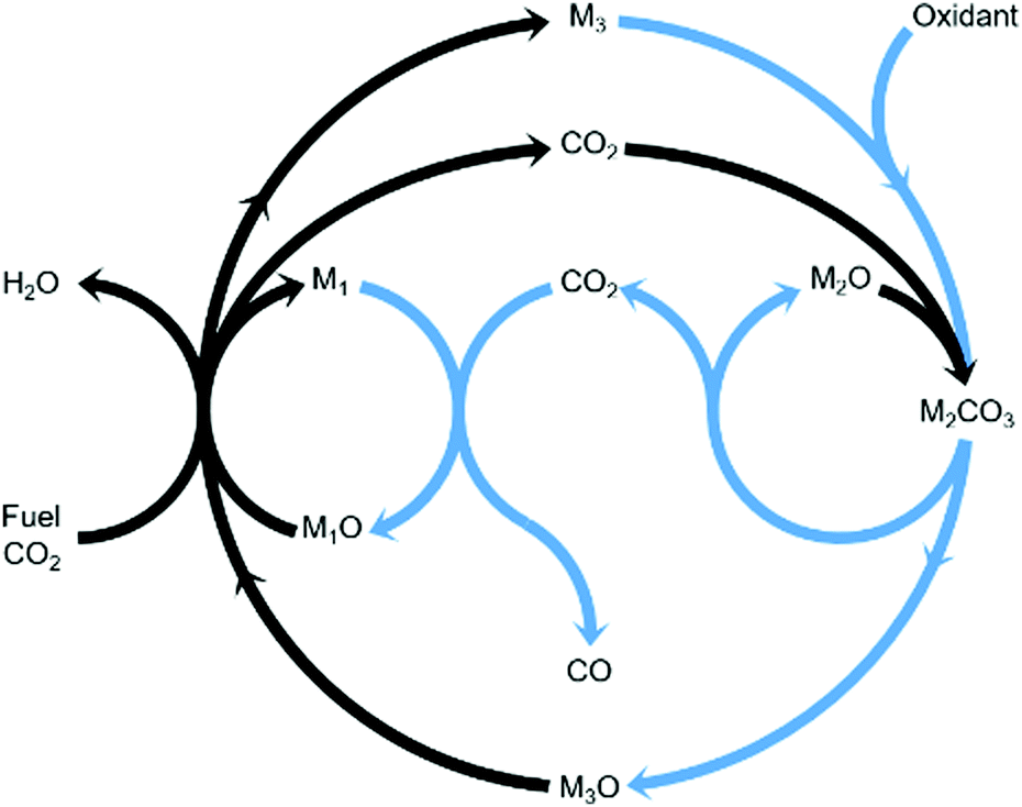
Chemical looping is an emerging technology that provides, among other advantages, inherent separation of reaction products.11,12 Compared to the steady-state rWGS catalytic reaction, using chemical looping can overcome equilibrium limitations,13 improve heat management of the process, and fully exploit the chemical energy available in the steel mill gases to produce a CO/CO2 stream. In this work, we propose an innovative strategy to convert CO2 to CO using three metal oxides with different functionalities in one process as displayed in Fig. 1. The three metal oxides deployed in this strategy can, for example, be abundant and non-toxic metal oxides such as Fe3O4, CaO, and Mn3O4. Among the gases produced in the steel industry, the blast furnace gas (BFG) is primarily targeted.14 With approximately 5% H2, 24% CO, 24% CO2, and the rest inert (mostly N2) on a molar basis, the BFG is the most abundant steel mill gas and also the most difficult to use for applications other than combined heat and power generation.7,15
 |
| | Fig. 1 General concept18 of a two-step process wherein a feed gas containing fuel(s) and CO2 (see black arrows) come into contact with metal oxide pairs that can oxidise fuel(s) partially (M1O/M1) and almost completely (M3O/M3) and a metal oxide (M2O) that is capable of capturing the produced CO2 in the form of a carbonate (M2CO3) under the process conditions of the first step. When the feed gas is switched to an oxidising gas (see blue arrows), at least one of the 2 redox pairs is capable of being oxidised by CO2 while the other is readily oxidised by O2, releasing heat and decreasing the partial pressure of CO2 such that the release of the captured CO2 and its conversion to CO are favoured. | |
The combined use of CaO and Fe3O4 has already been successfully demonstrated for CO2 capture and conversion for super-dry reforming of methane, which combines catalytic dry reforming and reverse water–gas shift.16,17 The additional use of another metal oxide, Mn3O4, ensures that the heat necessary for the reverse water–gas shift reaction is optimally provided and there are negligible emissions of unreacted CO and H2 from the process.18 Fe3O4 and Mn3O4 can both act as oxygen carriers (OCs), but the thermodynamic equilibrium oxygen partial pressure (pO2,eq)19 of Mn3O4 while transitioning to MnO is roughly 10 orders of magnitude higher than that of Fe3O4 to FeO and FeO to Fe. A higher pO2,eq indicates that near complete oxidation of fuel or reductants is thermodynamically favoured. CaCO3, acting as the CO2 carrier (CC), can be characterised by its thermodynamic equilibrium CO2 partial pressure (pCO2,eq) while transitioning to CaO. A low pCO2,eq indicates favourability towards carbonation i.e. capture of CO2. Depending on the selected operating conditions, the OCs and CC can be replaced by other oxides.3,20,21 The low costs, natural abundance, and environmentally benign nature of iron, manganese, and calcium oxides make them a preferable choice for industrial application. In Fig. S1 and S2 (ESI†), the temperature dependence of pCO2,eq and pO2,eq of the oxides used for the experimental work is displayed. Depending on the kinetics, time-scales, and optimum conditions of the desired chemical reactions, the process could either be carried out in a series of packed bed reactors, in moving beds, or in interconnected fluidised bed reactors.
One of the challenges of deploying chemical looping on a commercial scale is its relative complexity and high capital expenses.22,23 Thus, in this work, the proposed technology is first assessed from a techno-economic and exergetic perspective based on process simulations for an industrial production unit. The techno-economics and exergy efficiencies are compared to catalytic rWGS with conventional downstream separation processes. Catalytic rWGS is chosen as a benchmark for fair comparison because the presented process concept, in essence, breaks down the rWGS reaction into two steps. Although catalytic rWGS is currently not practiced on an industrial scale, it is gaining increased attention because of its sound ability to promote carbon circularity via CO2 utilisation and its technological maturity.24,25 The proposed process concept, in its entirety, is experimentally demonstrated in a fixed bed reactor set-up. In the forthcoming sections, the methods used for the simulation, analyses, and experimental work are outlined and the results of the applied methods are presented and discussed.
Methods
Process simulation
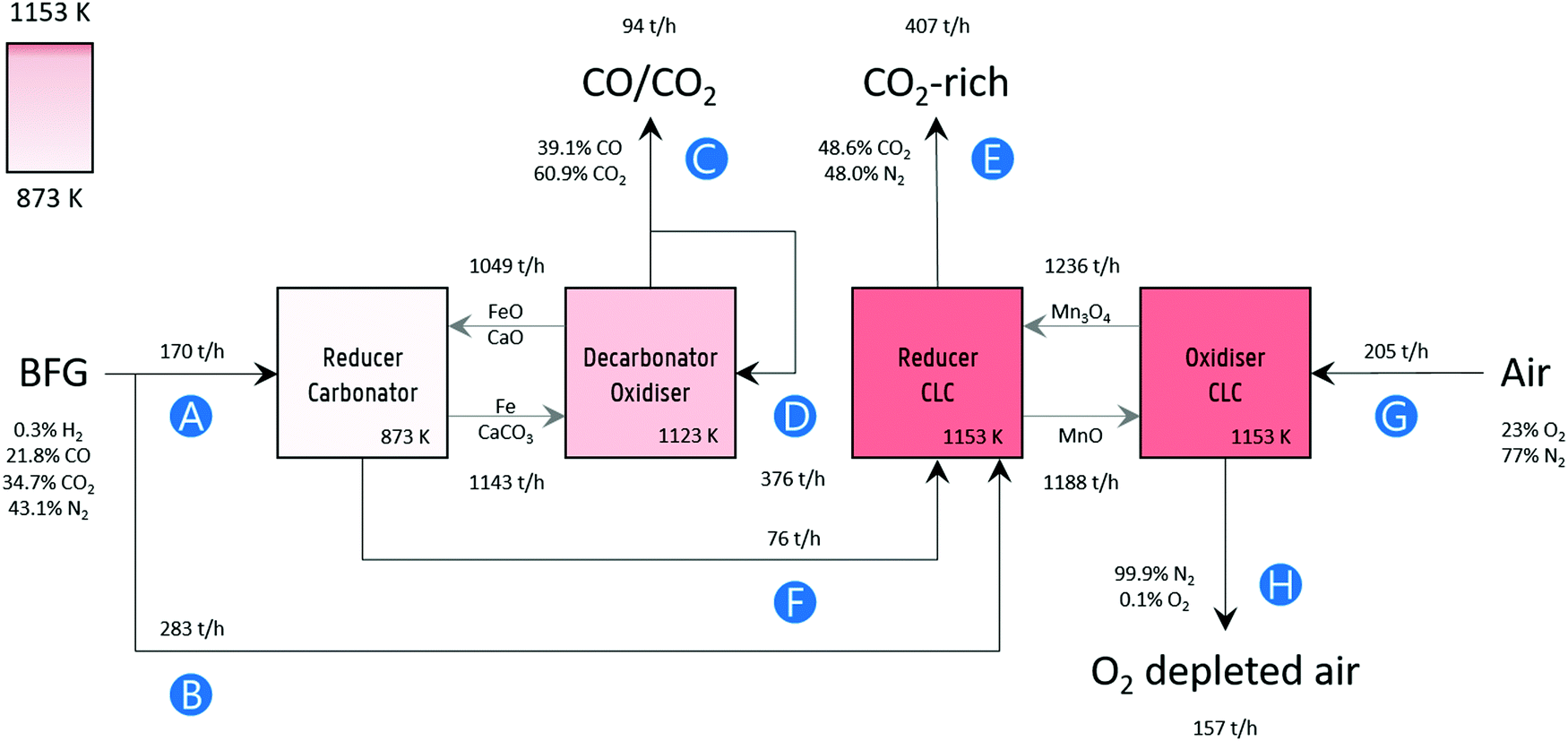
Process simulation was performed in Aspen Plus® V10, assuming fluidised bed reactors for the sake of simplicity. A block flow diagram of the process with mass flows is displayed in Fig. 2. The BFG utilised in the process corresponds to the production of approximately 2.6 megatonnes (Mt) of steel per year,15 which is typical for an integrated steel mill. Fig. 2 also presents the main specifications of the process simulation. Further details of the flowsheet (Fig. S7, ESI†) are listed in Table S1 (ESI†). Unless mentioned otherwise, other specifications were the default values of the simulator.
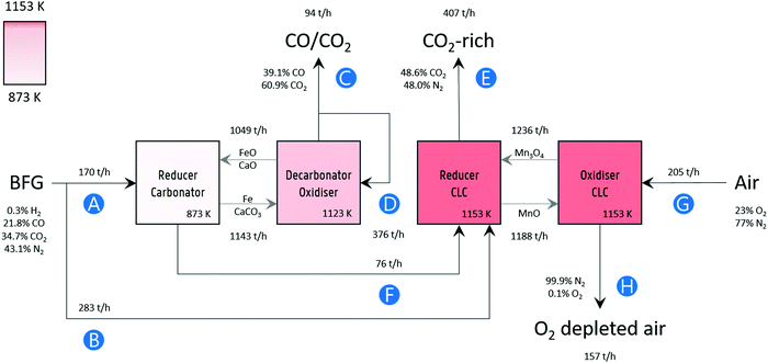 |
| | Fig. 2 Block flow diagram of the process concept with mass flow rates. Labels: (A) BFG feed for producing a CO/CO2 product stream (C), (B) additional BFG feed for generating the heat via chemical looping combustion to fulfil the heat demand in the decarbonator–oxidiser, (D) recycled portion of product stream as a sweep or fluidising gas, (E) CO2 released by combusting additional BFG and partly oxidised BFG (F) via chemical looping combustion (CLC), (G) air fed to replenish the lattice oxygen consumed during CLC, and (H) O2 depleted air. The compositions of the gas streams are given on a mass basis. Note that, for brevity and simplicity sake, the flows of inert solids MgAl2O4, and CeO2 that are used for imparting stability to the oxygen carriers (FeOx and Mn3O4) and CO2 carrier (CaCO3) and of the make-up flows are not displayed. Details are mentioned in Table 1 and in Fig. S7 (ESI†). | |
Table 1 Specifications of the process simulation. Capital letters in brackets refer to the labels in Fig. 2
|
|
Reducer–carbonator |
Decarbonator–oxidiser |
Reducer CLC |
Oxidiser CLC |
| Temperature [K] |
873 |
1123 |
1153 |
1153 |
| Pressure [kPa] |
101 |
101 |
101 |
101 |
| Inlet gas flow [kg s−1] |
(A) = 47 |
(D) = 4 × (C) = 104 |
(B) + (F) = 100 |
(G) = 57 |
| Inlet gas composition [mass basis] |
0.3% H2 |
|
0.4% H2 |
|
| 21.8% CO |
39.1% CO |
17.5% CO |
77% N2 |
| 34.7% CO2 |
60.9% CO2 |
27.5% CO2 |
23% O2 |
| 43.1% N2 |
|
54.4% N2 |
|
|
|
|
0.2% H2O |
|
| Inlet solid flow [kg s−1] |
222 |
248 |
432 |
420 |
| Inlet solids composition [mass basis] |
31% FeO |
20% FeO |
79% Mn3O4 |
25% Mn3O4 |
| 34% MgAl2O4 |
32% MgAl2O4 |
21% MgAl2O4 |
22% MgAl2O4 |
| 29% CaO |
13% CaO |
|
53% MnO |
| 6% CeO2 |
5% CeO2 |
|
|
|
|
6% Fe |
|
|
|
|
23% CaCO3 |
|
|
| Design specifications |
Corresponds to approximately 1 Mt/year of CO2 emissions if the inlet gas had been combusted |
80% of the outlet gas is recycled |
Inlet gas flow (B) adjusted such that the sum of heat produced in CLC equals heat requirement of decarbonator-oxidiser |
Inlet gas flow (G) adjusted to oxidise all MnO. |
The experimental results of this work show that 80% Mn2O3/MgAl2O4 is very stable for chemical looping combustion of the blast furnace gas (BFG). Based on the experimental results, the circulation rate of Mn3O4 displayed in Fig. 2 was determined assuming a conservative solids conversion of 70%. Similarly, 50% Fe2O3/MgAl2O4 is known to have very high chemical stability and an average residual oxygen transfer capacity between 24 to 31% after 1000 redox cycles (assuming redox transitions between Fe and FeO).26 The solids circulation rate of FeOx was determined using these values. Finally, the data from Fu et al.27 reporting CaO conversion of around 50% was used to determine the circulation rate of CaO in the process simulation. It should be noted that higher conversions of synthetic CO2 carriers over multiple cycles have been reported.28 Given the high chemical stability of the oxygen carriers, the make-up ratio of fresh oxygen carrier to the process was determined by the attrition rate of the materials. Based on the attrition resistance of a manganese-based oxygen carrier estimated by Costa et al.,29 it was assumed that the lifetime of the 80% Mn2O3/MgAl2O4 is 11![[thin space (1/6-em)]](https://www.rsc.org/images/entities/char_2009.gif) 000 hours. Similarly, the lifetime of 50% Fe2O3/MgAl2O4 is assumed to be 1250 hours, corresponding to the attrition resistance of an Fe-based oxygen carrier based on the work by Gayan et al.30 It is noteworthy that Fe-based oxygen carriers prepared via more sophisticated synthesis techniques with estimated lifetime of up to 33000 hours have also been reported.31 The ratio of the molar flow rate of CaO to that of the sum of CO and CO2 (CO is expected to be oxidised by FeO to form CO2) is approximately 2 and it is assumed that the ratio of fresh make-up sorbent to the sum of the molar flow rates of CO and CO2 is 0.05 (5%), corresponding with the results reported by Fu et al.27 Based on the analysis and assumptions discussed above, it is estimated that the amounts of fresh 80% Mn2O3/MgAl2O4, 50% Fe2O3/MgAl2O4, and 83% CaO/CeO2 would approximately be 1 kt per year, 5 kt per year, and 77 kt per year respectively. To put this into perspective, for the simulated production of 2.6 Mt per year of steel, the requirement of iron ore and limestone in the blast furnace alone is approximately 468 and 67 kt per year.7
000 hours. Similarly, the lifetime of 50% Fe2O3/MgAl2O4 is assumed to be 1250 hours, corresponding to the attrition resistance of an Fe-based oxygen carrier based on the work by Gayan et al.30 It is noteworthy that Fe-based oxygen carriers prepared via more sophisticated synthesis techniques with estimated lifetime of up to 33000 hours have also been reported.31 The ratio of the molar flow rate of CaO to that of the sum of CO and CO2 (CO is expected to be oxidised by FeO to form CO2) is approximately 2 and it is assumed that the ratio of fresh make-up sorbent to the sum of the molar flow rates of CO and CO2 is 0.05 (5%), corresponding with the results reported by Fu et al.27 Based on the analysis and assumptions discussed above, it is estimated that the amounts of fresh 80% Mn2O3/MgAl2O4, 50% Fe2O3/MgAl2O4, and 83% CaO/CeO2 would approximately be 1 kt per year, 5 kt per year, and 77 kt per year respectively. To put this into perspective, for the simulated production of 2.6 Mt per year of steel, the requirement of iron ore and limestone in the blast furnace alone is approximately 468 and 67 kt per year.7
In order to compare the proposed process in Fig. 2 with conventional technology, a process combining rWGS followed by a downstream separation train was also simulated (block diagram with mass flows depicted in Fig. S5 and flowsheet in Fig. S6, ESI†). The BFG fed to the rWGS process has the same composition as that in the chemical looping process (stream A in Fig. 2). By setting the temperature of the rWGS reactor to 866 K, an outlet flow of CO equivalent to that of the proposed chemical looping process was achieved. Pressure swing adsorption (PSA) was chosen for H2 separation from the mixed product stream because it is the most mature and widely used technology to separate H2 from a syngas mixture.32 It should be noted that separating H2 from mixtures containing less than 15 mol% H2 (H2 content of the gas after rWGS is 3 mol%) is not straightforward for conventional technologies such as PSA, membrane separation, and cryogenic distillation.33,34 Due to the large quantity of N2 to be separated, cryogenic distillation was selected for the separation of N2 from the product mixture of the rWGS reactor because of its competitiveness at larger scales.35 Freezing of CO2 in the distillation column could possibly be avoided by using advanced technologies such as CFZ™ (controlled freezing zone) that would help save the capital expenses of a separate CO2 removal unit.36 The small amount of methane produced in the rWGS process is neglected and its separation was not modelled.
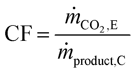
The carbon footprint (CF) of the process is defined using eqn (2),37 where ṁCO2,E is the mass flow rate of CO2 in stream E and ṁproduct,C is the mass flow rate of the product stream C, inclusive of CO and CO2 (see Fig. 2 for the alphabetic labels). Note that the carbon footprint as defined in this study accounts only for the CO2 emissions caused by the process and can, thus, be classified as Scope 1 emissions.38
| |  | (2) |
The carbon footprint of the catalytic rWGS, defined as the mass ratio of the CO
2 released to the environment and the 50% CO/CO
2 product stream, is highly dependent on the greenhouse gas emissions intensity of electricity production because electricity constitutes the majority of its external energy demand owing to its downstream separation processes. Based on the values of 2019 in the EU, it is assumed that the greenhouse gas emissions intensity of electricity from the grid is 255 kg equivalent-CO
2 MW
−1 h
−1.
39
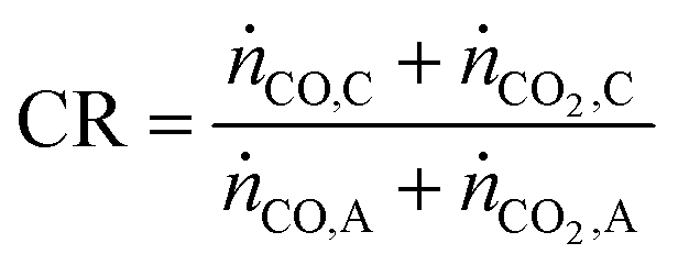
Apart from the carbon footprint, another metric useful for indicating the performance of the proposed chemical looping process is the carbon recovery (CR) defined by eqn (3), where ṅCO,C and ṅCO2,C are the molar flow rates of CO and CO2 in the product stream C and ṅCO,A and ṅCO2,A are their molar flow rates in feed stream A. The carbon recovery is the fraction of the amount of carbon fed (see stream A in Fig. 2), in the form of CO and CO2, to the reducer–carbonator which is transferred to the product stream (see stream C in Fig. 2).
| |  | (3) |
For rWGS, the heat necessary for the chemical reaction is obtained from combusting excess unreacted H
2 separated in the PSA (Fig. S5, ESI
†) instead of combusting a carbonaceous fuel. Thus, the carbon recovery of the rWGS is effectively 1.
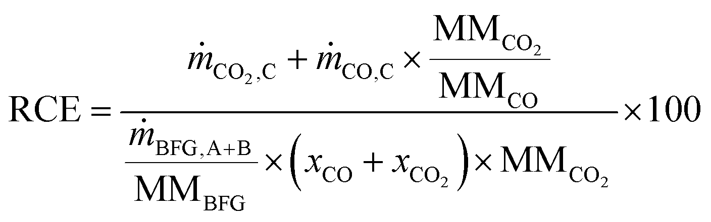
The reduction of CO2 emissions (RCE) when using BFG is calculated using eqn (4), where and ṁCO,C are the mass flow rates of CO2 and CO in outlet stream C, ṁBFG,A+B is the mass flow rate of the inlet BFG (A and B), MMBFG is the average molar mass of BFG, and xCO and are the mole fractions of CO and CO2 in the BFG.
| |  | (4) |
The denominator on the right hand side of
eqn (4) shows the amount of CO
2 that would be emitted if BFG would be combusted in a power plant (instead of being separated and used in the chemical industry) and the numerator shows the CO/CO
2 stream (C in
Fig. 2) that could be used in the chemicals industry or for the production of synthetic fuels.
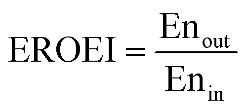
To assess the energy efficiency of the proposed process, the energy return on energy invested (EROEI)40 displayed in eqn (5) was calculated. This metric is the ratio of the energy output and the energy input of the process calculated using Aspen Plus. For the chemical looping process, the energy output comprises the CO/CO2 product stream and heat that can be used for generating electricity, whereas the energy input comprises only the BFG. On the other hand, for the catalytic steady-state rWGS process, the output comprises the CO/CO2 product stream and a separate H2 stream, while the energy input comprises the BFG and the electricity demand for the downstream separation processes. It is noteworthy that the analyses are limited to the investigated processes and the surroundings41 and do not take into account, for example, the energy efficiency with which electricity is supplied to the catalytic steady-state rWGS process.
| |  | (5) |
Exergy analysis
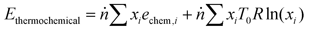
An exergy analysis was carried out using the results of the process simulation. Exergy of a system is defined as the maximum shaft work that can be done by the composite of the system and a specified reference environment.42 The total exergy (Etotal) of a stream is defined as the sum of its physical and thermochemical exergy (eqn (6)).| | | Etotal = Ephysical + Ethermochemical | (6) |
The physical exergy (Ephysical) was estimated using Aspen Plus with a reference state of 298 K and 101 kPa (the so-called “dead state”). The thermochemical exergy of the streams was calculated using eqn (7), where ṅ is the total molar flow rate of the stream, xi is the molar fraction of the ith component, echem,i is the standard chemical exergy of the ith component from Szargut,43R is the universal gas constant, and T0 is the reference temperature, i.e. 298 K. The latter part of eqn (7) associated with mixing exergy is assumed to be inapplicable to solids. The scope of the exergy analysis is limited to the streams and blocks depicted in Fig. 2 for the chemical looping process and in Fig. S5 (ESI†) for the catalytic rWGS.| | 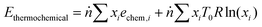 | (7) |
The exergy from a heat source Ephysical,Q at a temperature T is given by eqn (8), where Q is the amount of heat released and T0 is the reference temperature, i.e. 298 K.| | 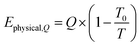 | (8) |
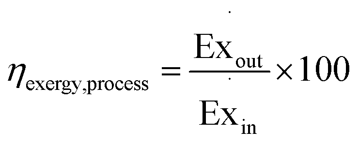
The exergy efficiency of the process, ηexcergy,process, is then given by eqn (9).| |  | (9) |
The exergy efficiency of the H2 PSA column (ηexergy,PSA) is calculated using the relation derived by Dunikov and Blinov44 and presented by eqn (10). A number of simplifying assumptions were made such as no exergy losses due to transient heat losses caused by the heat of adsorption/desorption and 100% product, i.e. H2 recovery. pin and pout were assumed to be 6300 kPa and 580 kPa based on typical industrial values.32 The partial pressure of desorbed H2 (pH2 in eqn (10)), was assumed to be 101 kPa. Recovery of work from expanding the tail gas from 580 kPa to 101 kPa was neglected. The H2 from the PSA was assumed to have a purity of 100%.| | 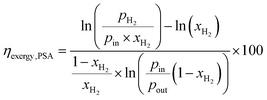 | (10) |
For cryogenic distillation, the energy input, in the form of electricity is estimated using empirical relations derived by Lange45 using the so-called “distillation resistance” Ω in °C−1 given in eqn (11), where wN2 is the mass fraction of N2 in the inlet stream and BPN2 and BPCO are the boiling points of N2 and CO in °C. The boiling points of N2 and CO are present in the denominator because N2 is the product to be separated and CO is the component with the next highest boiling point in the feed stream.| | 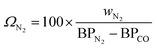 | (11) |
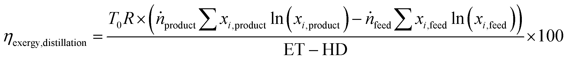
The energy transfer (ET) and heat transfer duty (HD) in GJ per tonnefeed for carrying out the distillation are given by eqn (12) and (13). These equations are based on industrial distillation columns for distilling components whose boiling point ranges from −250 °C to 136 °C for the top stream (lighter component) and from −210 °C to 350 °C for the bottom stream (heavier component). Thus, they are expected to be applicable for the separation of N2 (boiling point = −196 °C) from a mixture containing CO, CH4, and CO2 with boiling points equal to −191, −161, and −78 °C respectively.45 The deviation for the energy transfer duty (eqn (12)) and heat duty (eqn (13)) are ±1 and ±0.7 GJ per tonnefeed.Since the majority of the energy input for cryogenic distillation is required by pumps and compressors, the difference between the energy transfer duty (which includes the energy consumption from pumps and compressors) and heat duty is assumed to be the electrical energy (electrical energy ≈ exergy) input to drive the separation. The exergy efficiency (ηexergy,distillation) of the cryogenic distillation column is given by eqn (14), where the denominator indicates the minimum reversible work required to bring about the separation and the subscripts ”feed” and “products” refer to the mole fraction of the ith component in the feed and product.46| |  | (14) |
The minimum reversible work displayed in the denominator of eqn (14) is used for determining the energy required for separating H2O from the product mixture of rWGS, i.e., it is assumed that separation of H2O from the mixture has an exergy efficiency of 100%.
Techno-economic assessment
The price of the feedstock BFG was calculated using its lower heating value (2.6 GJ per tonne) and the average EU natural gas cost for non-household consumers based on its gross calorific value in 2020 (3.4 EUR per GJ for consumption higher than 130 MW – band I647). Assuming that natural gas is 100% methane (with a higher calorific value of 55.5 GJ per tonne), the price of BFG was estimated at 9 EUR per tonne, in agreement with estimations made by others.48
The cost of product stream (cproduct) was calculated using eqn (15) as a first approximation, where ci and wi are the cost and mass fraction of the ith component. The production of polyols can sequentially utilise the CO2 and CO content of the product gas stream, thereby making the simple cost estimation employed here reasonable.
| | | cproduct = cCO2wCO2 + cCOwCO | (15) |
The cost of producing commercial CO
via the widely used steam methane reforming process followed by rWGS is highly dependent on the cost of natural gas and amounts to roughly double the price of methane on a mass basis.
49 Using the price of natural gas mentioned above, the cost of CO was estimated to be 390 EUR per tonne, corresponding well with costs of CO reported in literature.
17,50 The cost of CO
2 was assumed to be 50 EUR per tonne.
51 As the product streams from both processes have approximately 50 mol% CO/CO
2 content, the price of the product stream is between 180 and 190 EUR per tonne.
Capital investment (CI) inside battery limits (ISBL) calculations were made using empirical relations derived by Lange52 given in eqn (16). The values were converted to 2020 equivalent USD using the US Bureau of Labor Statistics’53 inflation calculator and then converted to EUR at 0.9 EUR per USD.
| | | CI(ISBL) = 2 × (ET)0.65 | (16) |
It is noteworthy that the estimations made by this approach have an accuracy of −50 to +100%, but serve very well for comparing the novel process with more conventional processes. A Lang factor of 4 was used to estimate the capital expenses outside battery limits (OSBL) (see
eqn (17)), thereby adding a conservative buffer to the capital expenses estimated using
eqn (16).
| | | CI(OSBL) = 4 × CI(ISBL) | (17) |
A capital charge (CaCh) of 12% per year was used for the proposed chemical looping process as well as the steady-state catalytic rWGS.
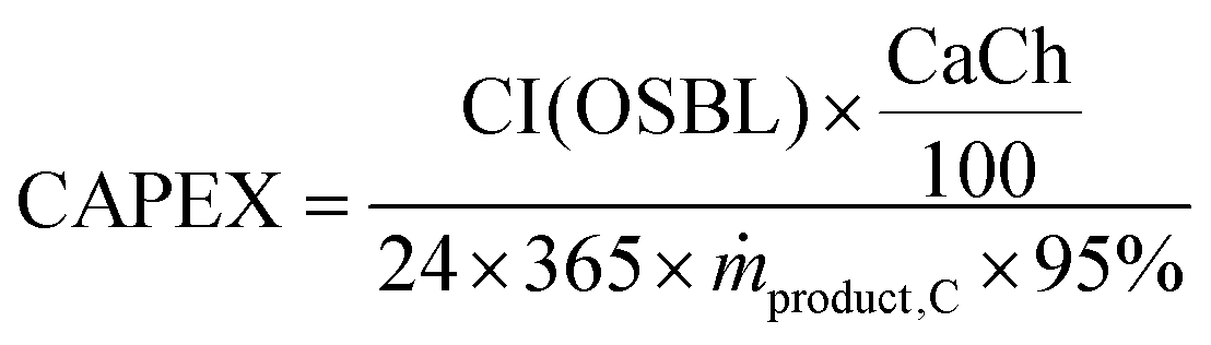
54 Assuming that the plant is operational throughout the year with 5% downtime, the annualised capital expenses (CAPEX) per tonne of product produced are calculated using
eqn (18). Note that CI (OSBL) in the
eqn (18) is converted to EUR
2020.
| | 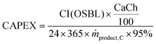 | (18) |
Operating expenses are composed of the cost of feedstock (BFG), cost of the materials for the proposed chemical looping process and the catalytic rWGS process, operation and maintenance (O&M) costs (4% of the capital costs inside battery limits per year
55), and the net amount of electricity (if required). The net amount of electricity necessary for running the H
2-PSA column is calculated by taking into account the exergy efficiency (see
eqn (10)) and the minimum reversible work necessary to bring about the separation (see denominator of
eqn (14)), while assuming that all energy would be supplied by electricity. For the sake of simplicity, the electricity requirement for operating the distillation column to cryogenically separate N
2 from the CO, CO
2, and N
2 mixture is assumed to be the difference between the energy transfer duty (
eqn (12)) and the heat duty (
eqn (13)). The heat duty, which typically requires natural gas, is assumed to be negligible. The viability of this simplified calculation scheme was tested for O
2 production in a conventional cryogenic air separation unit (ASU) and was able to predict its energy consumption with an accuracy of ±10% (further details are in Section S1.4, ESI
†).
For the proposed chemical looping process, the cost of materials included the cost of oxygen carriers 50% Fe2O3/MgAl2O4 and 80% Mn2O3/MgAl2O4 and the CO2 sorbent 83% CaO/CeO2, all of which had been used for the experimental demonstration. These costs were estimated using the step-based method described by Baddour et al. and are expected to have an accuracy of ±20%.56,57 The oxygen carriers studied in this work, 50% Fe2O3/MgAl2O4 and 80% Mn2O3/MgAl2O4, were estimated to have a cost of 1100 EUR per tonne and 1330 EUR per tonne (see Tables S2 and S3 of ESI†), close to the values reported in literature.54 The CO2 carrier, 83% CaO/CeO2, was estimated to cost 390 EUR per tonne, approximately 10 times higher than the cost of natural limestone.58 Detailed calculations are presented in the ESI† (Section S1.3.1) with due considerations to the lifetime of the materials. A Ni/Al2O3 catalyst, known to be effective for rWGS,59 was selected as the catalyst of choice for rWGS because of its lower cost compared to platinum group metal (PGM) catalysts. The annualised cost of the catalyst was conservatively estimated by assuming that the catalyst consumption is 0.01 kg per tonneproduct, one order of magnitude lower than the ideal catalyst consumption.37 Total operating expenses (OPEX) are, thus, given by eqn (19) as the sum of the costs of feedstock and materials (F&M), O&M, and electricity (if purchased).
| | | OPEX = cF&M + cO&M + celectricity | (19) |
The proposed chemical looping process is a source of excess heat that can be effectively used for electricity generation using steam turbines. Assuming that the steam turbines have a conservative exergy efficiency of 48%
60 (corresponding to an electrical efficiency of 33% for the chemical looping process, a conservative value for gas-fed chemical looping combustion at atmospheric pressure
61), electricity can be effectively sold to the grid or its purchase for the steel mill avoided at a cost of 0.04 EUR per kW per h,
62 corresponding to the 2020 electricity price in the EU for a consumption higher than 150 GW h (band I6). Other sources of revenue include the sale of excess H
2 (at the price of 2000 EUR per tonne
63) and revenue from recovering Ni from spent catalysts for the catalytic steady state rWGS. For the proposed chemical looping process, sale of scrap metal (oxides) also generates some revenue. The sale of N
2 (purity > 99%) from the CLC oxidiser (see stream H in
Fig. 2) or from the cryogenic distillation of the steady state rWGS process (stream D in Fig. S5, ESI
†) is not considered in this analysis. Further details of the costs to generate the revenue are given in the ESI
† (Section S1.3.1). The production cost is the sum of the capital and operating expenses as displayed in
eqn (20).
The net income (NI) is calculated using
eqn (21), wherein revenue is generated from the sale of products
i.e. chemicals (CO, CO
2, H
2), electricity, and solid materials (spent oxygen carriers, CO
2 carriers and catalyst).
Material synthesis and characterisation
The oxygen carriers, 50% Fe2O3/MgAl2O4 and 80% Mn2O3/MgAl2O4, were synthesised via co-precipitation using the procedure described by Dharanipragada et al.64 The CO2 carrier, 83% CaO/CeO2 was synthesised via a wet physical mixing route using calcium D-gluconate monohydrate (Sigma-Aldrich, 98% purity by mass) and cerium nitrate hexahydrate (Sigma-Aldrich, 99.9% purity by mass) with deionised water as solvent based on the work by Liu et al.65 The calcium precursor, calcium D-gluconate monohydrate, was selected based on a previous study that indicated that CaO-based sorbents made using the selected precursor show high retention of their CO2 sorption capacity upon repeated cycling.66 The support material CeO2 was chosen to enhance the stability of CaO.67,68
The prepared materials were characterised using N2 sorption at 77 K (Micromeritics Tristar II), X-ray diffraction (XRD) with Cu-Kα radiation (Siemens Diffractometer Kristalloflex D5000), energy dispersive X-ray (EDX) spectroscopy (INCA x-act extension from Oxford instruments), and temperature programmed reactions (TPRe) (Micromeritics Autochem II 2920) such as temperature programmed carbonation-decarbonation using CO2 (CO2-TPCD), temperature programmed reduction using H2 (H2-TPR) followed by temperature programmed oxidation using CO2 (CO2-TPO). Further details related to the characterisation techniques and the results are described in the ESI† (Section S2.1).
Experimental proof of concept
For the experiments related to the proof of the process concept, a 7.5 mm ID quartz fixed bed reactor with a length of 470 mm and a wall thickness of 1 mm was used as shown in Fig. 3. A type K thermocouple was axially placed inside the material bed to measure the temperature at the centre of the bed. The reactor was enclosed in an electrically operated oven with three heating zones, which were equipped with three thermocouples to provide feedback for temperature control of the furnace. Mass flow controllers (MFCs) (Bronkhorst EL-Flow) were used to control the inlet gas and a fast switching pneumatic valve allowed to change the inlet feed gas to the fixed bed. The outlet of the reactor was connected to a sampling port with an on-line mass spectrometer (MS) (Pfeiffer Vacuum OmniStar QMS 301). The product gases were analysed by tracking H2, He, H2O, CO, O2, Ar, and CO2 signals at 2 AMU (atomic mass unit), 4 AMU, 18 AMU, 28 AMU, 32 AMU, 40 AMU, and 44 AMU respectively. Fragmentation patterns were taken into account and Ar was used as the internal standard for quantification of the molar flow rates. The MS was regularly calibrated with reference gases flowing through an empty reactor at room temperature under the assumption that reactions would not occur either because of very slow kinetics and/or unfavourable thermodynamics.
 |
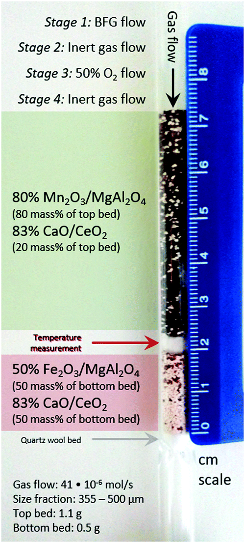
| | Fig. 3 Laboratory reactor bed to carry out the proof of concept experiments and experimental specifications. The scale bar on the right indicates the length in cm. Gas flow: 41 × 10−6 mol s−1. Size fraction of solids: 355–500 μm. Top bed (manganese oxide and calcium oxide): 1.1 g. Bottom bed (iron oxide and calcium oxide): 0.5 g. | |
A synthetic mixture with the following composition was used to mimic BFG: 5.1 mol% H2, 23.8 mol% CO, 24.1 mol% CO2, 7% He, and 40% Ar. The reactor outlet pressure was controlled at 120 kPa by means of a back pressure regulator and the total inlet gas flow was kept constant at 41 × 10−6 mol s−1. For the experiment, the top bed consisted of a 1.1 g physical mixture containing pellets of 80% Mn2O3/MgAl2O4 and 83% CaO/CeO2 in a 9:2 mass ratio and the bottom bed consisted of a 0.5 g mixture containing pellets of 50% Fe2O3/MgAl2O4 and 83% CaO/CeO2 in a 1:1 (by mass) ratio loaded in the reactor on a quartz wool plug. The sieve fraction of the pellets was in the range of 355 to 500 μm to limit the pressure drop in the bed. The two beds were arranged to exploit the functionalities of all the materials used: in the top bed, during reduction, complete oxidation of feed gas was achieved with CO2 capture and during oxidation, fed O2 was completely consumed while liberating heat to be used for CaCO3 decomposition. In the bottom bed, during reduction, H2 and CO in the BFG reduced FeOx, complemented by CO2 capture via CaO. During oxidation, CO2 released upstream and in situ was converted to CO while regenerating FeOx and CaO. Each cycle consisted of 4 stages: (1) reduction with BFG for 240 seconds, (2) reactor purge with inert Ar for 60 seconds to sweep out unconverted reactants and products, (3) oxidation with 50% O2 in Ar for 60 seconds to ensure that heat generated is quickly and used for the reaction instead of being dissipated to the surroundings, and (4) purge with inert Ar for 1500 seconds to sweep out unconverted reactants and products. 30 redox cycles were executed, of which the first 5 had a reduction (stage 1) time of 180 s instead of 240 s to gauge the operating limits of the system.
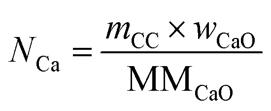
The total moles of Ca, Fe, and Mn (only when used) in the reactor are calculated using eqn (22)–(24).
| | 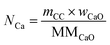 | (22) |
| |  | (23) |
| |  | (24) |
The utilisation of the oxygen transfer capacity and the CO
2 carrying capacity in both half-cycles were calculated using
eqn (25)–(27).
| | 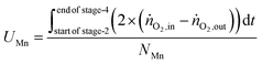 | (25) |
| | 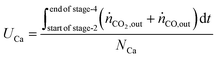 | (26) |
| |  | (27) |
For the calculations of material utilisation, it is assumed that the fresh materials placed in the reactor consists exclusively of Fe
2O
3 and MgAl
2O
4 in the Fe-based oxygen carrier, CaO and CeO
2 for the CO
2 carrier, and, Mn
2O
3 and MgAl
2O
4 in the Mn-based oxygen carrier. The presence of CeO
2 for oxidation of reductants is neglected since in the given reaction conditions it can only contribute a small portion of its lattice oxygen atoms while being reduced to non-stoichiometric CeO
2−δ (
δ < 0.1).
69
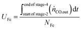
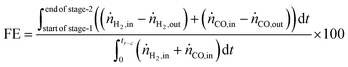
The fuel efficiency (FE) of the process is calculated using eqn (28).
| |  | (28) |
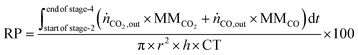
The reactor productivity (RP) for the proof of concept experiments is given by
eqn (30), where
r = bed radius = 3.75 × 10
−3 m,
h = height of the bed ≈7.3 × 10
−2 m, and CT = total cycle time = 0.52 hours.
| |  | (29) |
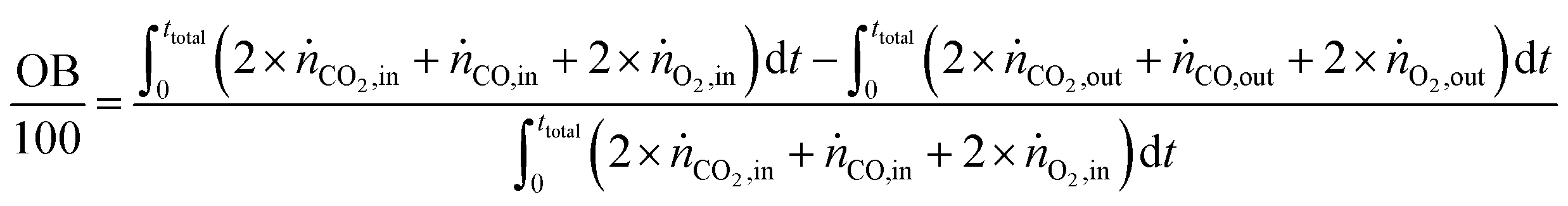
The carbon balance (CB) and oxygen balance (OB) are computed using
eqn (30) and (31).
| | 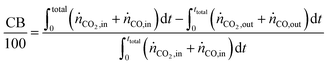 | (30) |
| | 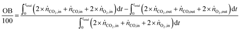 | (31) |
Carbon and oxygen balances were closed within 10% and 15% for all experiments.
Results and discussion
Process simulation
The base case of the proposed process was simulated by setting the reducer–carbonator to a temperature of 873 K to maximise carbon capture because the pCO2,eq of CaCO3 at this temperature is approximately 0.3 kPa (eqn (32)). The capture of CO2 favours oxidation of CO in the BFG (eqn (33)) via Le Chatelier's principle, leading to an overall carbon recovery of around 98% (eqn (3)). A higher temperature would result in lower carbon recovery.| |  | (32) |
| |  | (33) |
The higher carbon recovery comes at the cost of lower utilisation or oxidation of H2 (eqn (34)) in the BFG (around 11% of inlet H2 is oxidised when the reducer–carbonator is at 873 K). Higher H2 utilisation is favoured at higher temperature (see Fig. S4 for an equilibrium diagram, ESI†) because of reduction of FeO and also due to increased favourability of the rWGS (eqn (1)).| |  | (34) |
The reduction–carbonation reaction is highly exothermic and its heat can be utilised within the steel mill or be used for the generation of electricity.
Conversely, the decarbonation–oxidation step is highly endothermic (eqn (32) and (33) from right to left) and is operated at a temperature of 1123 K to avoid the use of N2 or another inert to decarbonate the CaCO3. The production of CO during decarbonation decreases the partial pressure of CO2, thereby extending the lifetime of the CO2 carrier70 and improving the kinetics of decarbonation.71 The heat for the chemical reactions during the decarbonation–oxidation step and the heat to increase the temperature of the solids is provided by the near complete oxidation of the gas stream exiting the reducer–carbonator (see F in Fig. 2) and additional BFG (see B in Fig. 2) via chemical looping combustion (CLC), operated isothermally at 1153 K, a temperature higher than that at which the decarbonator-oxidiser (1123 K) is operated to enable heat transfer. The gas exiting the oxidiser of CLC (stream H in Fig. 2) consists of 99%+ N2. Although this stream, in this study, is not considered to be of any economic value apart from the heat it carries, it could be useful to feed the loop seals (non-mechanical pneumatic valves72) in case the proposed process is carried out in a moving bed or a fluidised bed reactor or be used as a purge gas in case a series of fixed bed reactors are deployed.
The gas exiting the reducer of CLC (see E in Fig. 2) comprising 39 mol% (50 mass%) CO2 on a dry basis is the source of process CO2 emissions. These emissions are accounted for in the carbon footprint of the process (see eqn (2)), which amounts to 2.1 tonnes of CO2 per tonne of product. This value is lower than the maximum value of 6 tonnes of CO2 per tonne of product suggested for sustainable development of commodities and fuels.37 It is noteworthy that the high fraction of CO2 in this stream (roughly 10 times larger than from conventional gas fired combustion73) also makes it more favourable for economical CO2 capture and storage or further utilisation.74 A summary of the outlet gas streams from the chemical looping process is displayed in Table 2.
Table 2 Specifications of the outlet gases of the process simulation (see C, E, and H in Fig. 2). Capital letters in brackets refer to the labels in Fig. 2
| Stream label |
C |
E |
H |
| Temperature [K] |
1123 |
1153 |
1153 |
| Pressure [kPa] |
101 |
101 |
101 |
| Outlet flow [kg s−1] |
26 |
44 |
113 |
| Composition [mass basis] |
39.1% CO |
48.6% CO2 |
99.9% N2 |
| 60.9% CO2 |
48.0% N2 |
0.1% O2 |
|
|
3.3% H2O |
|
|
|
CO < 16 ppm |
|
|
|
H2 < 0.2 ppm |
|
For the rWGS simulation, a fraction of the H2 separated from PSA is combusted using air (air to fuel ratio ≈1.3) to form a product stream containing only H2O and depleted air. The fraction of H2 combusted was determined by the heat necessary for the endothermic rWGS. The carbon recovery of rWGS is, thus, 100% and its carbon footprint is largely determined by the greenhouse gas emissions intensity of the electricity the process uses for carrying out the separation, which is further discussed in the next sections. The outlet of the rWGS contains a small fraction of CH4 formed due to methanation (≈0.3 mol%), which is not considered for separation.
The BFG of a steel mill is known to contain trace quantities of sulphur (approximately 10 ppm) in the form of H2S or COS.7 These sulphurous compounds are expected to be captured by CaO via reactions displayed in eqn (35) and (36). The formed CaS cannot be used for CO2 capture and may be considered to be a part of spent CO2 sorbent. In the base case, the molar flow of CaO in the fresh CO2 sorbent added (make-up flow of the CO2 sorbent) is 3 orders of magnitude higher than that of H2S in the inlet stream. Thus, the sulphur in the BFG can be effectively removed from the outlet CO/CO2 stream (see C in Fig. 2).
| |  | (35) |
| |  | (36) |
The low amounts of inlet sulphur in the form of H
2S are not expected to affect the iron oxide or the manganese oxide because of unfavourable thermodynamics.
75 Thus, when additional BFG is fed to the chemical combustion loop, the sulphurous compounds are expected to be oxidised to SO
x and exit in the outlet CO
2-rich stream (see E in
Fig. 2). For the rWGS simulation, it is assumed that the trace quantities of sulphur are removed from the BFG before being fed to the rWGS reactor.
By separating and using the CO/CO2 stream by the proposed process for the production of chemicals, a 37% reduction in CO2 emissions (eqn (4)) can be achieved, when compared to the best available technology of combusting the BFG with air for combined heat and power. Apart from the production of polyols76,77 and the production of synthetic fuels,10,78,79 other pathways to use the CO/CO2 product stream from the proposed process could be production of basic chemicals such as acetic acid, formic acid, etc.5,80 using renewable H2. By using bio-coal instead of fossil coal in the blast furnace of the steel mill,81 the products formed by the CO/CO2 gas stream of the proposed chemical looping process can be made free of fossil fuels.
The chemical looping process has an EROEI (eqn (5)) of 0.95, which is three times higher than that of the catalytic steady-state rWGS. This metric indicates the energy efficiency or the so-called first law efficiency of the two processes. The quality of the energy is taken into account by considering exergy, as described below, to arrive at the exergy efficiency or the second law efficiency.
Exergy analysis
The energy requirements for the chemical looping process comes solely from the BFG. Since a part of this BFG is combusted, it is important to estimate the “useful work” (exergy) while taking such an approach. If only the thermochemical fraction of the total exergy is considered (see eqn (7)), the exergy efficiency of the chemical looping process is around 32% (eqn (9)). Using high temperatures in chemical looping allows a large fraction of the heat (contributing to physical exergy in eqn (6)) required for the transformation of feed to products to be recovered as useful work. The major sources of heat for recovery in the chemical looping process are (1) the reduction–carbonation step, (2) the hot product gases (streams C and E in Fig. 2), and (3) the hot solids exiting the reduction–carbonation step. When accounting for the recoverable heat at high temperature, the exergy efficiency of the proposed chemical looping process can be as high as 82%. Typically, high temperature heat can be converted to electricity using a steam turbine. Taking into account the exergy losses for steam turbines (exergy efficiency is assumed to be 48%), the anticipated exergy efficiency of the chemical looping process is 59.8%. The breakdown of the exergy discussed above is illustrated in Fig. 4, wherein the anticipated exergy efficiency is the sum of physical exergy recoverable as electricity and thermochemical exergy of products.
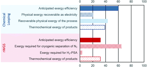 |
| | Fig. 4 Exergy analysis of the proposed chemical looping process (in blue) and conventional rWGS with downstream purification (in red). For the sake of brevity, the negligible exergy required for separation of H2O is not displayed. The displayed values represent the exergy content in different streams/processes normalised to the total exergy input. | |
For the rWGS process, the exergy input comprises mainly imported electricity to drive the separation processes. The thermochemical exergy of products is slightly higher (about 1%) than that of the feed because CO is more exergetic than H2 and heat is consumed to convert H2 to CO (see eqn (1)). Fig. 4 shows that a large fraction of the total exergy is required for the cryogenic separation of N2 and this requirement dwarves the exergy required for the H2 separation by PSA. An important conclusion from this analysis is that increasing the conversion of H2 in rWGS by increasing the temperature or not separating H2 at all can only slightly improve the exergy efficiency of rWGS. The exergy efficiency of the cryogenic distillation to separate N2 was estimated viaeqn (14) to be around 1%, which is not surprising considering the large amounts of N2 to be removed from the outlet stream of rWGS and the small difference of about 4 K in the boiling points of N2 and CO. The atypical task of removing H2 in a highly diluted stream via PSA also caused a lower exergy efficiency of about 4% based on eqn (10). Thus, the anticipated exergy efficiency, as displayed in Fig. 4, is simply the difference between the total exergy input and the exergy requirement for H2-PSA and cryogenic separation of N2, which is equal to 32.0%. The above analysis shows that the proposed chemical looping process is exergetically far more efficient than chemical conversion via steady state rWGS followed by conventional separation techniques.
Techno-economic assessment
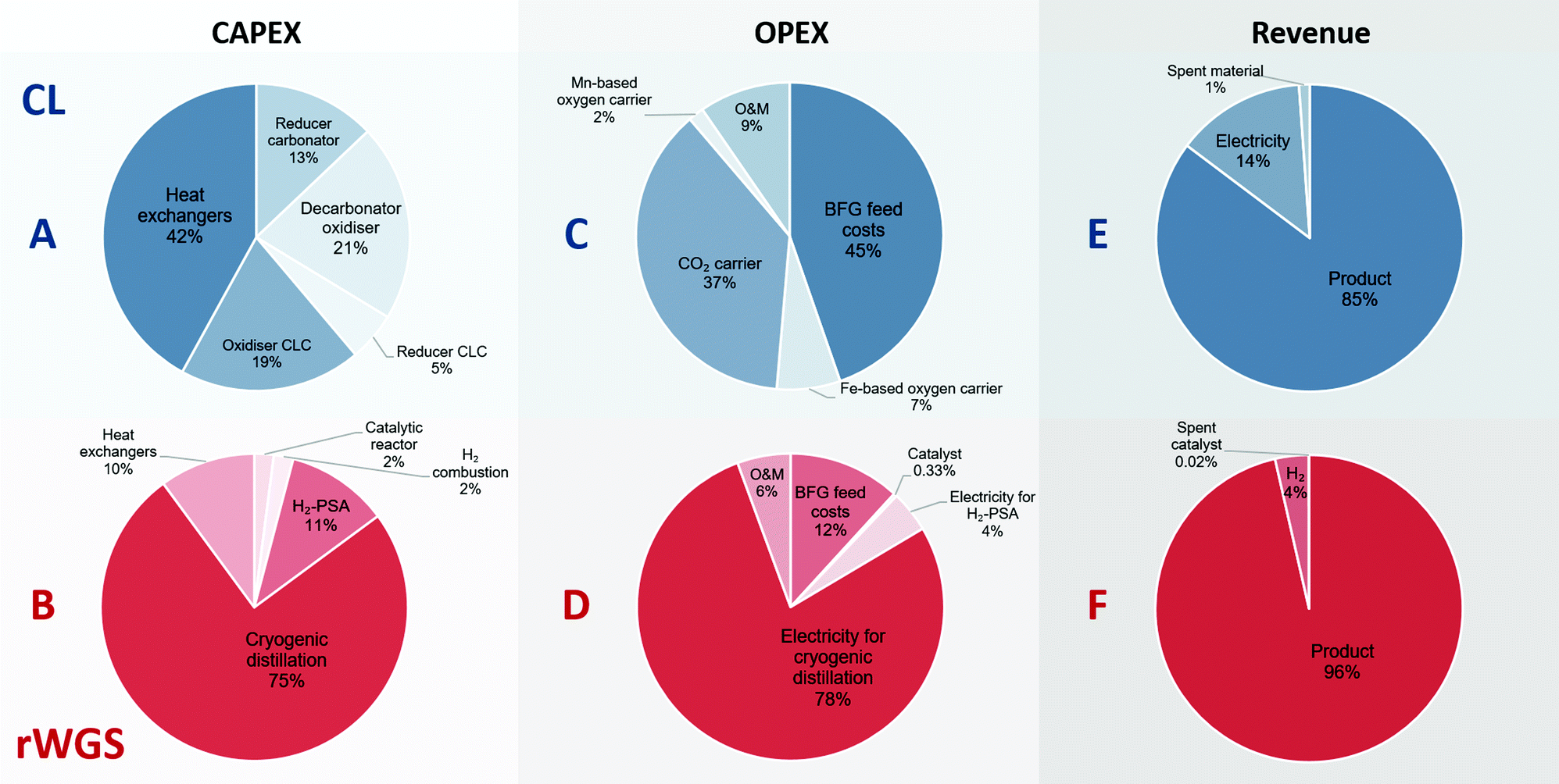
Chemical looping makes use of a solid intermediate that undergoes several redox cycles (in the case of oxygen carriers) or carbonation-decarbonation cycles (for CO2 carriers) over the course of its useful lifetime. Thus, the cost of these solids and their lifetime are important parameters that can influence the economic feasibility of the process. Synthetic CO2 carriers such as the one used in this work are known to be resistant against sintering compared to most forms of natural limestone and thus, are expected to have a longer lifetime.28,82,83 Upon reaching the end of their useful lifetime, large quantities of these solid materials become available for other purposes. The advantage of proximity to the steel mill is that the Fe-based oxygen carrier and a portion of the CaO based CO2 carrier can be used for the production of steel. The rest of the spent CO2 carrier could find use in the cement industry.84,85 The manganese based oxygen carrier with a very high loading (80 mass%) could replace manganese ore used in the metallurgical industry. Similarly, it is assumed that Ni from the spent Ni-based catalyst can be recovered, thereby allowing to minimise the cost of fresh catalysts. The prices of the spent materials are displayed in Table S5 (ESI†) and are based on 5 to 10 year average prices from public market data unless mentioned otherwise.
Fig. 5 shows the breakdown of the CAPEX, OPEX, and revenue of the proposed chemical looping process and the catalytic rWGS with downstream separation processes. The capital expenses for chemical looping (Fig. 5A) are dominated by the heat exchangers to recover the physical exergy of the process in the form of heat followed by the decarbonator–oxidiser, which requires the highest heat input in the process. For the corresponding rWGS case, the separation processes, H2-PSA and cryogenic distillation, are most prominent, emphasising the complexity of separation processes to produce a CO/CO2 stream.86,87 As the chemical energy of the BFG is solely responsible for driving the proposed chemical looping process, the cost of feedstock BFG forms nearly 50% of the OPEX (see Fig. 5C). For energy-intensive production of chemicals, it is very typical that the cost of feedstock is the principal contributor to the overall production costs.88 Because of the high make-up of fresh CO2 carrier, the operating expenses of the proposed chemical looping process is significantly influenced by the cost of the CO2 carrier. The relatively longer lifetime of the oxygen carriers minimises their contribution to the overall OPEX despite being roughly 3 times more expensive than the CO2 carrier on a mass basis. On the other hand, more than 75% of the OPEX of the rWGS derives from the electricity demand for cryogenic distillation. As the CAPEX and OPEX are strongly dependent on the energy transfer duty, the separation processes of the rWGS having the highest energy requirements determine the overall production costs. Indeed, the cost of CO/CO2 production by directly applying cryogenic separation to the BFG is expected to be similar. The OPEX breakdown of the rWGS also shows that the low consumption of the catalyst makes the cost of replacing the catalysts negligible. Finally, for the proposed chemical looping process, apart from the CO/CO2 product stream, electricity can also be a co-product along with the sale of spent oxygen carriers and CO2 carriers. It is noteworthy that if the CO2 leaving the process (see stream E in Fig. 2) is taken into account, the greenhouse gas emissions intensity of the produced electricity is 1 order of magnitude higher than that of the electricity available in the grid.39 This is because the electricity in the proposed chemical looping process is generated at the expense of carbon-rich BFG originating from fossil coal. For the rWGS process, the excess H2 is a co-product. Interestingly, although the production of H2 is approximately 300 times lower (per unit of mass) than that of the main product, it does contribute significantly to the revenue because of its high value.63 Due to the strong dependence of the rWGS process on electricity, it has an indirect carbon footprint (eqn (2)) of 0.8 tonnes of CO2 per tonne of CO/CO2 product.39
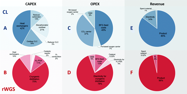 |
| | Fig. 5 Breakdown of the contribution to the costs constituting the CAPEX, OPEX, and revenue for the proposed chemical looping (CL) process and rWGS process with downstream separation. A, C, and E (in blue) show the breakdown of the CAPEX, OPEX, and revenue generated for the proposed chemical looping process (total CAPEX: 122 EUR2020 per tonneproduct and OPEX: 100 EUR2020 per tonneproduct), whereas B, D, and F (in red) show the corresponding breakdown for the rWGS (total CAPEX: 99 EUR2020 per tonneproduct and OPEX: 136 EUR2020 per tonneproduct). O&M stands for operation and maintenance. | |
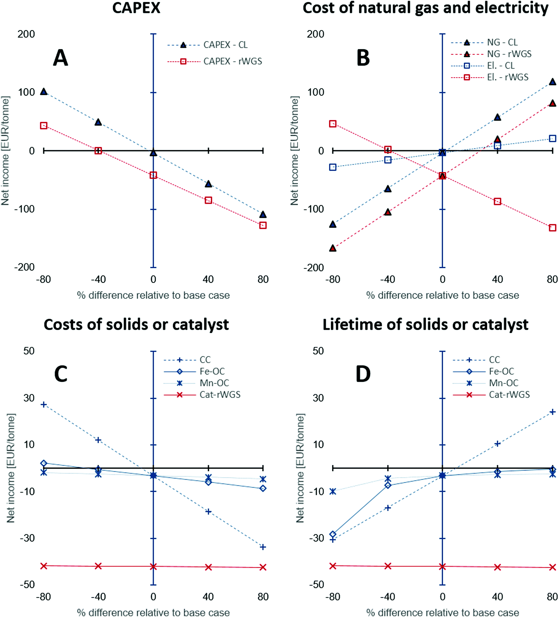
The CAPEX estimations used in this study have a fairly large degree of uncertainty between −50 to 100%. Thus, a sensitivity analysis was performed to study the influence of the under- or overestimation of CAPEX and other variables such as the cost of natural gas, electricity, and the costs and lifetime of the solids or catalyst used. Fig. 6 shows the results of the sensitivity analysis. The origin on the x-axis represents the base case. Each variable in the analysis was varied independently by keeping the other variables constant at their base values. The y-axis displays the “net income” calculated using eqn (21), wherein all the terms are normalised against the product CO/CO2 stream.
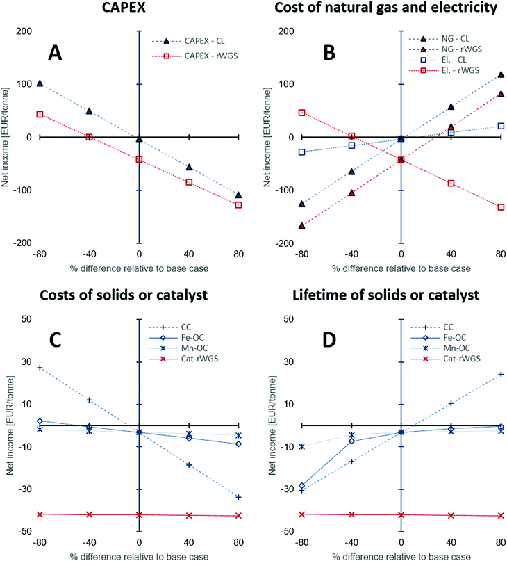 |
| | Fig. 6 Sensitivity analysis to examine the effect of (A) CAPEX estimation, (B) cost of natural gas and electricity, (C) costs of solids: oxygen carriers and CO2 carrier, or catalyst, and (D) their lifetime on the net income defined as the difference between the revenue and the production costs, i.e., CAPEX and OPEX. Abbreviations used in the figure legends: CL – chemical looping, NG – natural gas, El. – electricity, CC – Ca-based CO2 carrier, Fe-OC – iron based oxygen carrier, Mn-OC – manganese based oxygen carrier, and Cat-rWGS – Ni/Al2O3 catalyst for the reverse water–gas shift reaction. | |
The sensitivity analysis on the CAPEX displayed in Fig. 6A, shows that for higher than expected capital expenses, significant incentives (for example, an increase of CO2 market prices to approximately 220 EUR2020 per tonne from 50 EUR2020 per tonne) would be required to make the processing of the BFG competitive with conventional technologies to produce CO (steam methane reforming followed by reverse water–gas shift87,89). The CAPEX of the chemical looping process is around 18% higher than that of the rWGS process and hence, its sensitivity analysis shows a steeper slope for the change in net income with change in the CAPEX. Fig. 6B shows the influence of the cost of electricity and natural gas on the processes. Depending on the energy mix of the electricity grid, the cost of electricity and natural gas may be highly linked, but in this case, they are treated as independent from each other to highlight the peculiarities of the chemical looping process compared to rWGS followed by downstream separation processes. The price of commercial carbon monoxide is strongly dependent on the price of natural gas,49 thus, an increase in the price of natural gas increases (by a factor of 2 assuming a linear correlation) the market price of CO, thereby increasing the revenue of both processes, which results in an increased net income. The rWGS process is heavily dependent on electricity and thus, lower electricity prices result in increased net income, whereas for the chemical looping process lower electricity prices cause a loss of revenue since the proposed process is a net generator of electricity. An increase in the price of natural gas is expected to increase the cost of electricity when the electricity in the grid comes from natural gas combustion. An increased price of natural gas would result in a more pronounced increase in the market price of CO. In such a scenario, the chemical looping process would be heavily favoured because of increased revenue from sale of CO and surplus electricity.
The low catalyst consumption in the rWGS makes the net income of the process almost invariant to the cost of the catalyst and its lifetime as seen in Fig. 6C and D. On the other hand, analysis shows that the net income is very sensitive to the CO2 carrier's cost and also its lifetime because of the large quantities of the material consumed by the process. A decrease in the cost of the CO2 carrier by 40% or an increase of its lifetime by 40% causes the net income to increase to a value between 15 to 20 EUR per tonneproduct, which is significant for a bulk chemical when compared to the production costs (sum of CAPEX and OPEX) of about 210 EUR per tonneproduct (note that there exist other sources of revenue apart from the sale of product – see Fig. 5E). Compared to the CO2 carrier, the lifetime and costs of the oxygen carriers have a milder influence on the net income because the quantities involved are 1 order of magnitude smaller.
In the above discussion, changes in the price of CO2 or carbon tax/carbon credit were not considered. The carbon footprint (eqn (2)) of the CO/CO2 product stream is significantly larger than that of the rWGS process (2.1 tonnes per tonne of product vs. 0.8 tonnes per tonne of product). However, it must be noted that the source of CO2 emissions in the proposed chemical looping process (stream E in Fig. 2) is highly concentrated in CO2 (mass fraction of CO2 on dry basis: 0.5), thereby making it much more compliant for CO2 capture. Using the equation derived by House et al.74 based on the Sherwood plot, it can be shown that the cost of capturing CO2 from the proposed chemical looping would be more than 3 times lower than it would be for the flue gas of a natural gas fired power plant, which is estimated to be approximately 70-80 $2020 per tonne90,91 (calculations are presented in the Section S1.4, ESI†). Thus, it would be more economical to completely eliminate CO2 emissions from the proposed chemical looping process than in the conventional rWGS followed by downstream separation via mature technologies under atypical circumstances.
Experimental proof of concept
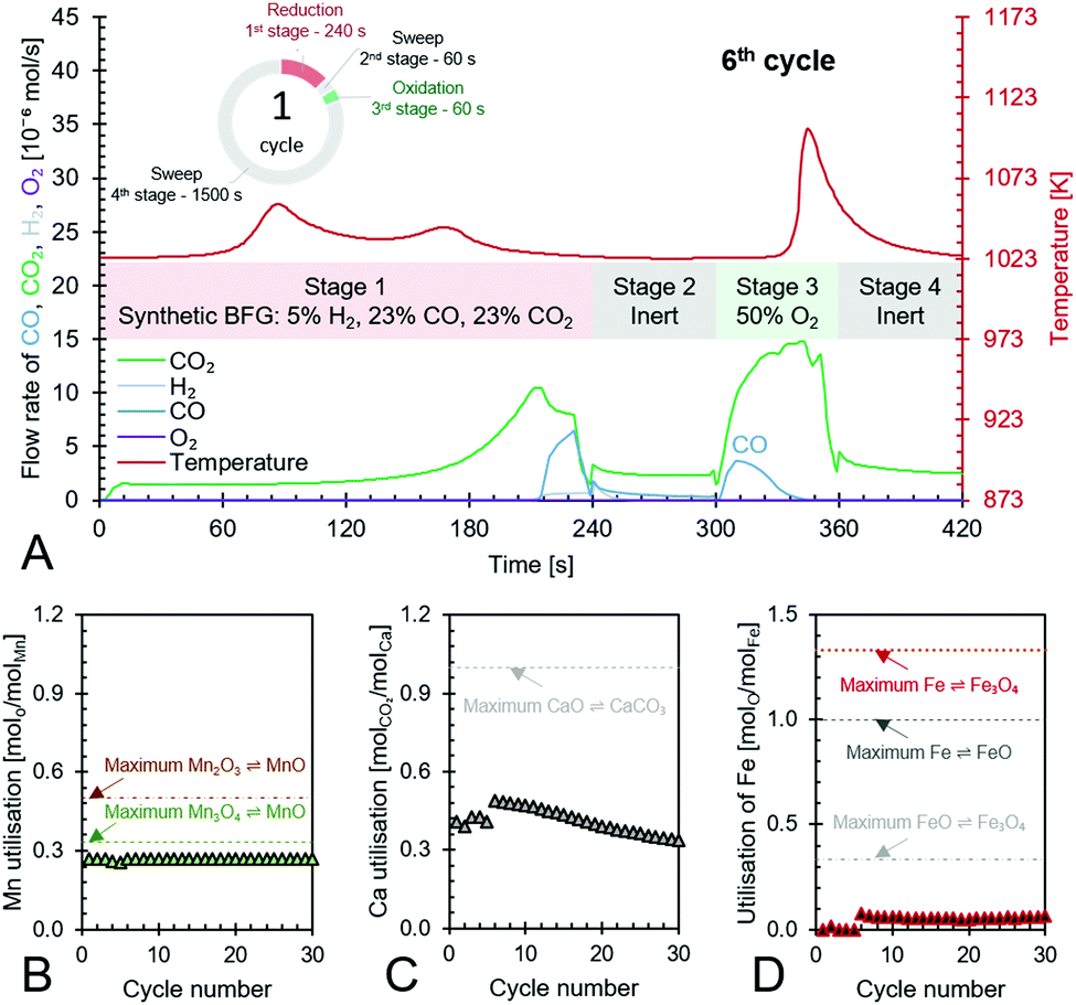
The experimental proof of concept involving the use of 3 metal oxides, namely, CaO, FeOx (x = 1 to 1.3), and Mn3O4 was carried out at a temperature of approximately 1023 K. This temperature was chosen because it provided a good compromise between carbon recovery (eqn (3)) and the kinetics of decarbonation. All the materials used, FeOx (x < 1.3) for converting CO2 to CO, CaO for CO2 capture and carbon recovery, and MnO for O2 capture and heat generation were functional over multiple cycles as displayed in Fig. 7B–D. The fuel efficiency (eqn (28)) for all cycles was higher than 90% and the reactor productivity (eqn (29)) was above 50 kgproduct m−3 h−1 for all the tested cycles.37,52,92
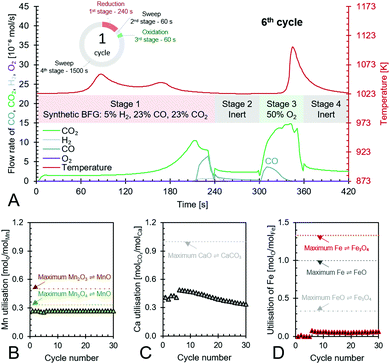 |
| | Fig. 7 Anti-clockwise from top to bottom – (A) the 6th cycle of the proposed chemical looping process showcasing its capabilities to use/store the chemical energy from synthetic BFG in stage 1 to produce CO (in stages 2 to 4) while completely using the fed O2 in stage 3 to create heat for the decarbonation of CaCO3, (B) – utilisation of Mn in the top portion of the bed and its maximum possible utilisation based on reaction stoichiometry, (C) – utilisation of Ca as CaO in the top and bottom beds of the reactor and its maximum possible utilisation based on reaction stoichiometry, and (D) – utilisation of Fe in the bottom bed and its maximum possible utilisation based on the transitions of its redox pairs Fe/FeO, Fe/Fe3O4, or FeO/Fe3O4. | |
Fig. 7A displays the experimental results of the 6th cycle as an example of a single cycle (corresponding experimental results in an empty reactor are shown in Fig. S23, ESI†). During the reduction stage (stage 1), the reduction of the oxygen carriers, Mn3O4 and FeOx, occurs with carbonation of CaO in an overall exothermic reaction. The exothermicity of the reaction causes the temperature to steadily increase. During this stage, only small amounts of H2 or CO break through the bed and the amount of CO2 in the outlet depends on the thermodynamic equilibrium partial pressure of CO2 while CaCO3 transitions to CaO, which is favourably lower at lower temperatures, and the reactivity of CaO. Fig. 7A shows that CO2 breakthrough occurs at about 200 s, indicating a limited reactivity of CaO despite excess quantities being available in the reactor (Fig. 7C). A higher reactivity of CaO would have resulted in further CO2 capture and consistently lower outlet CO2 flow. As large quantities of gases are captured in the reduction stage (roughly 50 vol% of the synthetic BFG contains CO and CO2, the majority of which is captured by CaO), the outlet molar flow rate of the gas decreases. In the second stage, a purge gas is introduced to the reactor with the same inlet molar flowrate as that in the reduction stage. This purge gas, Ar, favours the decarbonation reaction of CaCO3 because it decreases the partial pressure of CO2. The CO2 from the decarbonation reaction reacts with the reduced FeOx species to form CO (<2 × 10⁻⁶ mol s−1), which further accelerates the decarbonation reaction via Le Chatelier's principle.16 Because the decarbonation reaction is highly endothermic, visible from the decline in temperature during the second stage, an oxidant stream containing O2 is fed to the reactor in the oxidation stage (stage 3) to provide the heat necessary for decarbonation by oxidising the reduced MnO in the top bed. As the oxidant stream is fed to the reactor at the same inlet flow rate as the gases in the previous stages, the near complete consumption of O2 by oxidation of MnO (no O2 breakthrough observed) causes an overall decrease in the total flow rate. This is visible from the sudden decrease in the measured outlet flow rates of the different gases. As the third stage proceeds, the heat generated not only causes a notable increase in temperature but also favours the decarbonation reaction, which is proved by the increased flow rates of CO and CO2. Finally, in the fourth stage, a purge gas feed completes the cycle and prepares the reactor for the next cycle.
The manganese oxide oxygen carriers exhibit highly stable chemical reactivity over multiple cycles (Fig. 7B), thereby justifying the assumption for the process simulation and techno-economic study that attrition drives the requirement of fresh manganese oxide to be used in the process. Fig. 7C shows that the Ca utilisation is lower in the first 5 cycles. This was caused by the lower reduction time in the first 5 test cycles compared to the remaining 30 cycles. For the sake of completeness, the experimental results of the first 5 cycles are displayed in Fig. S18–S22 (ESI†). Loss of the chemical reactivity of CaO seen in Fig. 7C was likely caused by material sintering. However, this loss is taken into account for the techno-economic study by considering the addition of fresh CaO to the process (77 kt per year). Fig. 7D shows that Fe utilisation begins after a few cycles because of excess Mn3O4, which combusts all the inlet BFG preventing the FeOx in the bottom bed to be reduced during the first stage. Once the FeOx in the bottom bed is reduced, stable chemical reactivity is maintained throughout the tested cycles, which corroborates recent experimental findings93 and the assumptions made for the process simulation and techno-economic study. Fig. 7D also shows that there is sub-optimal utilisation of Fe. In a fixed bed reactor, higher fuel efficiency typically results in lower material utilisation. One way to circumvent this issue is to use a reverse flow reactor,13,94 wherein, if the oxidising flow inlet is from top to bottom (see Fig. 3), then the reducing gas inlet flow is from bottom to top or vice-versa. For fluidised bed or moving bed reactors, the complete oxidation of reductants to provide energy can simply be carried out in another set of reactor(s) as displayed in Fig. 2.
For the process simulations, a low temperature for the reduction-carbonation was used and a higher temperature for the decarbonator–oxidiser. In order to mimic these conditions, an independent experiment was performed with the Fe-based oxygen carrier, 50% Fe2O3/MgAl2O4 and the CO2 carrier, 83% CaO/CeO2 by imposing a temperature program (displayed in Fig. S24, ESI†). In this experiment, it is demonstrated that a molar CO:CO2 ratio of approximately 1 is achievable in the process with a reactor productivity in the range of 98 to 115 kg m−3 h−1.
Requirements of (a) large temperature changes in different steps of the process and (b) influx of new solids because of deactivation make fluidised beds or moving bed reactors the preferable choice for industrial operation because they avoid thermal stresses to the reactor's material of construction and facilitate uninterrupted operation.95 In moving bed reactors, highly exothermic and endothermic reactions can lead to significant heat management issues such as hot and/or cold spots. These issues can be managed more readily in fluidised bed reactors.96 Thus, for the given selection of metal oxides and inlet feed of BFG, fluidised bed reactors may be the preferred choice of reactor type. The operating conditions such as the requirement of temperatures in the different steps or half-cycles of chemical looping and the exothermicity or endothermicity of reactions are determined by the choice of metal oxides. Thus, by choosing metal oxides which facilitate isothermal operation and improve heat management (for example, by splitting the heat of combustion approximately equally over the reduction and oxidation half-cycles), the reactor choice can be further simplified. As for the optimisation of metal oxides, the use of computational screening of materials could facilitate the search for the ideal metal oxides combination for the proposed technology.20,21,97–99 A demonstration of this process on a pilot scale at optimum conditions would help bring it closer to practical implementation and provide data for further determining its technical and economic viability for large scale efficient utilisation of CO2.
Conclusions
A process concept based on chemical looping that exploits equilibrium oxygen partial pressure of metal oxides and equilibrium CO2 partial pressure of metal carbonates for the production of a CO-rich stream from any gas stream containing fuel and CO2 under optimal operating conditions was developed. This process concept, demonstrated in a laboratory fixed bed reactor, was adapted to completely utilise the chemical energy of a process gas from the steel industry, the blast furnace gas. The proposed process produces an enriched CO/CO2 stream free of N2 from the blast furnace gas, thereby avoiding the CO2 emissions that combustion of the blast furnace gas typically entails while providing the chemicals industry with valuable feedstock that can be used for creating carbon-based chemicals such as plastics or synthetic fuels.
The developed process makes use of materials composed of cheap and abundant metal oxides which are non-toxic, easy to prepare, use, and dispose. These materials can be, for example, oxides of iron, manganese, and calcium. The analysis carried out in this work shows that the chemical looping process with its advantage of inherent product separation makes it very competitive with a combination of commercially applied technologies to achieve the same performance. Moreover, the fact that the developed process operates at high temperatures between 873 K and 1153 K enables it to have a very high exergy efficiency. By implementing this technology, a 37% reduction in CO2 emissions can be achieved, when compared to the current best available technology of combusting the blast furnace gas with air. The rest of the CO2 emissions from the proposed process can be far more easily captured and stored or utilised to achieve net zero CO2 emissions than those from a conventional power plant.
Preliminary techno-economic assessment suggests that the developed process would be economically viable when the 50 mol% CO/CO2 is sold at a price of approximately 190 EUR per tonne. At this product price, the profits from the proposed chemical looping process for the base case scenario are higher than those from conventional steady-state catalytic reverse water–gas shift with downstream separation by 40 EUR per tonne. The economic viability of the process is strongly dependent on the cost and lifetime of the Ca-based CO2 carrier and the market price of natural gas and electricity.
Glossary
Abbreviations
| AMU | Atomic mass unit |
| ASU | Air separation unit |
| BFG | Blast furnace gas |
| BF-BOF | Blast furnace – basic oxygen furnace route for steelmaking |
| CC | CO2 carrier |
| CFZ | Controlled Freezing Zone – trademark of ExxonMobil |
| CLC | Chemical looping combustion |
| CL | Chemical looping |
| El. | Electricity |
| EDX | Energy dispersive X-ray spectroscopy |
| ISBL | Inside battery limits Ω |
| ID | Internal diameter in mm |
| kt | Kilotonne(s) |
| MFC | Mass flow controller |
| MS | Mass spectrometer |
| Mt | Megatonne(s) |
| NG | Natural gas |
| O&M | Operation and maintenance |
| OC | Oxygen carrier |
| OPEX | Operating expenses |
| OSBL | Outside battery limits |
| PGM | Platinum group metals |
| PSA | Pressure swing adsorption |
| TPCD | Temperature-programmed carbonation and decarbonation |
| TPO | Temperature-programmed oxidation |
| TPR | Temperature-programmed reduction |
| TPRe | Temperature-programmed reaction |
| XRD | X-Ray diffraction |
Symbols
| ΔG0 | Standard Gibbs free energy of reaction in kJ per mol |
| ΔH0 | Standard enthalpy of reaction in kJ per mol |
|
Ω
| Distillation resistance in °C−1 |
| BP | Boiling point in °C |
| CB | Carbon balance in % |
|
c
i
| Cost of materials or resources i expressed in EUR2020 per tonneproduct |
| CaCh | Capital charge in % per year. |
| CAPEX | Capital expenses in EUR per tonne of product |
| CF | Carbon footprint in tonnes of CO2 released to the environment per tonne of product |
| CI | Capital investment in million United States dollars of the year 2003 |
| CR | Carbon recovery in moles of carbon in product per mole of carbon fed |
| CT | Total cycle time in hours |
|
E
| Exergy in kJ mol−1 |

| Energy flow in MW |
| ET | Energy transfer duty in GJ per tonnefeed |

| Exergy flow in MW |
| FE | Fuel efficiency in % |
|
h
| Height of the fixed bed for the experimental proof of concept in m |
| HD | Heat duty in GJ per tonnefeed |
| MMi | Average molar mass of component or stream i in g mol−1 |
|
m
i
| Mass of component i in g |
|
ṁ
| Mass flow rate in tonnes per hour or kg s−1 |
|
ṅ
| Molar flow rate in mol s−1 |
| N | Moles of a particular element in the fixed bed |
| NI | Net income in EUR2020 per tonne |
| OB | Oxygen balance in % |
| OPEX | Operating expenses in EUR per tonne of product |
|
Q
| Heat released or required in MW |
| PC | Production costs in EUR per tonne of product |
|
p
CO2,eq
| Thermodynamic equilibrium CO2 partial pressure of a metal carbonate |
|
p
O2,eq
| Thermodynamic equilibrium oxygen partial pressure of a metal oxide |
|
r
| Radius of the fixed bed quartz reactor for the experimental proof of concept = 3.75 mm |
|
R
| Universal gas constant in kJ mol−1 K−1 |
| RP | Reactor productivity in kgproduct mreactor−13 h−1 |
| RCE | Reductions in CO2 emissions in % (when compared to the best available technology of combusting the steel mill gases for heat and/or electricity) |
|
t
| Time of half-cycle in seconds |
|
T
| Temperature in K |
|
U
x
| Utilisation of metal x in % |
|
w
i
| Mass fraction of component i in feed or product |
|
x
i
| Molar fraction of component i in feed or product |
Author contributions
VS: conceptualisation, formal analysis, investigation, methodology, visualisation, writing – original draft. LCB: conceptualisation, methodology, visualisation, writing – review and editing. HP: supervision, writing – review and editing. MS: project administration, supervision, funding acquisition, writing – review and editing. GBM: conceptualisation, funding acquisition, resources, supervision, visualisation, writing – review and editing. VVG: conceptualisation, methodology, funding acquisition, resources, supervision, visualisation, writing – review and editing.
Disclaimer
The information contained in this document has been prepared solely for the purpose of providing information about the Carbon4PUR consortium and its project. The document reflects only the Carbon4PUR consortium's view and the European Commission is not responsible for any use that may be made of the information it contains.
Conflicts of interest
A provisional patent (application ID: WO 2021/116064 A1) has been filed related to this work.
Acknowledgements
VS acknowledges financial support from the project Cabon4PUR which has received funding from the European Union's Horizon 2020 research and innovation programme under grant agreement no. 768919.
References
- J. P. Lange, Energy Environ. Sci., 2021, 14, 4358–4376 RSC.
- N. MacDowell, N. Florin, A. Buchard, J. Hallett, A. Galindo, G. Jackson, C. S. Adjiman, C. K. Williams, N. Shah and P. Fennell, Energy Environ. Sci., 2010, 3, 1645–1669 RSC.
- D. Maiti, B. J. Hare, Y. A. Daza, A. E. Ramos, J. N. Kuhn and V. R. Bhethanabotla, Energy Environ. Sci., 2018, 11, 648–659 RSC.
- B. Shao, G. Hu, K. A. M. Alkebsi, G. Ye, X. Lin, W. Du, J. Hu, M. Wang, H. Liu and F. Qian, Energy Environ. Sci., 2021, 14, 2291–2301 RSC.
- J. Arvola, J. Harkonen, M. Mottonen, H. Haapasalo and P. Tervonen, Low Carbon Economy, 2011, 2, 115–122 CrossRef.
- Material Economics, Industrial Transformation 2050: Pathways to net-zero emisisons from EU Heavy Industry, University of Cambridge Institute for Sustainability Leadership (CISL), 2019 Search PubMed.
-
R. Remus, M. A. Aguado-Monsonet, S. Roudier and L. D. Sancho, Best Available Techniques (BAT) Reference Document for Iron and Steel Production, European Commission; Joint Research Centre; Institute for prospective technological studies, Spain, 2013 Search PubMed.
- S. Inoue, H. Koinuma and T. Tsuruta, J. Polym. Sci., Part B: Polym. Lett., 1969, 7, 287–292 CrossRef CAS.
- M. R. Machat, J. Marbach, H. Schumacher, S. Raju, M. Lansing, L. C. Over, L. Adler, J. Langanke, A. Wolf, W. Leitner and C. Gürtler, React. Chem. Eng., 2022, 7, 580–589 RSC.
- Y. H. Choi, Y. J. Jang, H. Park, W. Y. Kim, Y. H. Lee, S. H. Choi and J. S. Lee, Appl. Catal., B, 2017, 202, 605–610 CrossRef CAS.
- X. Zhu, Q. Imtiaz, F. Donat, C. R. Müller and F. Li, Energy Environ. Sci., 2020, 13, 772–804 RSC.
- L.-S. Fan, L. Zeng, W. Wang and S. Luo, Energy Environ. Sci., 2012, 5, 7254–7280 RSC.
- I. S. Metcalfe, B. Ray, C. Dejoie, W. Hu, C. de Leeuwe, C. Dueso, F. R. Garcia-Garcia, C. M. Mak, E. I. Papaioannou, C. R. Thompson and J. S. O. Evans, Nat. Chem., 2019, 11, 638–643 CrossRef CAS.
- J. Collis, T. Strunge, B. Steubing, A. Zimmermann and R. Schomäcker, Front. Energy Res., 2021, 9 DOI:10.3389/fenrg.2021.642162.
- W. Uribe-Soto, J.-F. Portha, J.-M. Commenge and L. Falk, Renewable Sustainable Energy Rev., 2017, 74, 809–823 CrossRef CAS.
- L. C. Buelens, V. V. Galvita, H. Poelman, C. Detavernier and G. B. Marin, Science, 2016, 354, 449–452 CrossRef CAS PubMed.
- K. Verbeeck, L. C. Buelens, V. V. Galvita, G. B. Marin, K. M. Van Geem and K. Rabaey, Energy Environ. Sci., 2018, 11, 1788–1802 RSC.
-
V. Singh, V. V. Galvita, G. B. Marin and M. Saeys, WO 2021/116064 A1, 2021.
- A. Thursfield, A. Murugan, R. Franca and I. S. Metcalfe, Energy Environ. Sci., 2012, 5, 7421–7459 RSC.
- M. T. Dunstan, A. Jain, W. Liu, S. P. Ong, T. Liu, J. Lee, K. A. Persson, S. A. Scott, J. S. Dennis and C. P. Grey, Energy Environ. Sci., 2016, 9, 1346–1360 RSC.
- C. Y. Lau, M. T. Dunstan, W. Hu, C. P. Grey and S. A. Scott, Energy Environ. Sci., 2017, 10, 818–831 RSC.
- M. Bui, C. S. Adjiman, A. Bardow, E. J. Anthony, A. Boston, S. Brown, P. S. Fennell, S. Fuss, A. Galindo, L. A. Hackett, J. P. Hallett, H. J. Herzog, G. Jackson, J. Kemper, S. Krevor, G. C. Maitland, M. Matuszewski, I. S. Metcalfe, C. Petit, G. Puxty, J. Reimer, D. M. Reiner, E. S. Rubin, S. A. Scott, N. Shah, B. Smit, J. P. M. Trusler, P. Webley, J. Wilcox and N. Mac Dowell, Energy Environ. Sci., 2018, 11, 1062–1176 RSC.
- A. Lyngfelt, A. Brink, Ø. Langørgen, T. Mattisson, M. Rydén and C. Linderholm, Int. J. Greenh. Gas Control, 2019, 88, 38–56 CrossRef CAS.
- J. Han, J. Ind. Eng. Chem., 2021, 96, 213–218 CrossRef CAS.
- R. M. Bown, M. Joyce, Q. Zhang, T. R. Reina and M. S. Duyar, Energy Technol., 2021, 9, 2100554 CrossRef CAS.
- L. C. Buelens, A. N. V. R. Dharanipragada, H. Poelman, Z. Zhou, G. B. Marin and V. V. Galvita, J. CO2 Util., 2019, 29, 36–45 CrossRef CAS.
- C. Fu, S. Roussanaly, K. Jordal and R. Anantharaman, Front. Chem. Eng., 2021, 2 DOI:10.3389/fceng.2020.596417.
- A. N. Antzara, A. Arregi, E. Heracleous and A. A. Lemonidou, Chem. Eng. J., 2018, 333, 697–711 CrossRef CAS.
- T. R. Costa, P. Gayán, A. Abad, F. García-Labiano, L. F. de Diego, D. M. A. Melo and J. Adánez, Fuel Process. Technol., 2018, 178, 236–250 CrossRef CAS.
- P. Gayán, M. A. Pans, M. Ortiz, A. Abad, L. F. de Diego, F. García-Labiano and J. Adánez, Fuel Process. Technol., 2012, 96, 37–47 CrossRef.
- Y. De Vos, M. Jacobs, P. Van Der Voort, I. Van Driessche, F. Snijkers and A. Verberckmoes, Chem. Eng. J., 2017, 309, 824–839 CrossRef CAS.
-
D. Bonaquist, Analysis of CO2 emissions, reductions, and capture for large-scale H2 production plants, Praxair, USA, 2010 Search PubMed.
- Z. Du, C. Liu, J. Zhai, X. Guo, Y. Xiong, W. Su and G. He, Catalysts, 2021, 11(3), 393 CrossRef CAS.
- L. Vermaak, H. Neomagus and D. G. Bessarabov, Membranes, 2021, 11(4), 282 CrossRef CAS.
- S. Ivanova and R. Lewis, Chem. Eng. Prog., 2012, 108(6), 38–42 CAS.
- P. S. Northrop and J. A. Valencia, Energy Procedia, 2009, 1, 171–177 CrossRef CAS.
- J.-P. Lange, Nat. Catal., 2021, 4, 186–192 CrossRef CAS.
-
P. Bhatia, C. Cummis, A. Brown, D. Rich, L. Draucker and H. Lahd, Corporate Value Chain (Scope 3) Accounting and Reporting Standard, World Resources Institute and World Business Council for Sustainable Development, USA, 2011 Search PubMed.
- European Environment Agency, Greenhouse gas emission intensity of electricity generation in Europe, https://www.eea.europa.eu/data-and-maps/indicators/overview-of-the-electricity-production-3/assessment-1 (accessed 11/06/2021, 2021) Search PubMed.
- R. P. Lively, AlChE J., 2021, 67, e17286 CAS.
- R. Atlason and R. Unnthorsson, Energy, 2014, 67, 241–245 CrossRef.
-
I. Dincer and M. A. Rosen, Exergy, 2021, pp. 1–22 Search PubMed.
-
J. Szargut, Exergy method: technical and ecological applications, WIT Press, Southampton, 2005 Search PubMed.
- D. Dunikov and D. Blinov, Int. J. Hydrogen Energy, 2020, 45, 9914–9926 CrossRef CAS.
- J. P. Lange, ChemSusChem, 2017, 10, 245–252 CrossRef CAS.
- E. L. Cussler and B. K. Dutta, AlChE J., 2012, 58, 3825–3831 CrossRef CAS.
- European Commission, Gas prices components for non-household consumers – annual data, https://ec.europa.eu/eurostat/databrowser/view/nrg_pc_203_c/default/table?lang=en (accessed 11/06/2021, 2021) Search PubMed.
- M. Messagie, F. Boureima, J. Mertens, J. Sanfelix, C. Macharis and J. Mierlo, Energies, 2013, 6, 1217–1232 CrossRef CAS.
- S. Redl, S. Sukumara, T. Ploeger, L. Wu, T. Olshoj Jensen, A. T. Nielsen and H. Noorman, Biotechnol. Biofuels, 2017, 10, 150 CrossRef.
- S. Licht, H. Wu, C. Hettige, B. Wang, J. Asercion, J. Lau and J. Stuart, Chem. Commun., 2012, 48, 6019–6021 RSC.
-
D. Sheppard and C. Hodgson, Cost of polluting in EU soars as carbon price hits record €50, https://www.ft.com/content/2b965427-4fbc-4f2a-a14f-3be6019f0a7c (accessed 11/06/2021, 2021).
- J.-P. Lange, V. L. Sushkevich, A. J. Knorpp and J. A. van Bokhoven, Ind. Eng. Chem. Res., 2019, 58, 8674–8680 CrossRef CAS.
- U. S. B. o. L. Statistics, CPI Inflation Calculator, https://www.bls.gov/data/inflation_calculator.htm (accessed 11/06/2021, 2021).
-
R. W. Stevens Jr., D. L. Keairns, R. A. Newby and M. C. Woods, Handbook of Chemical Looping Technology, 2018, pp. 333–376 Search PubMed.
- S. Tian, J. Jiang, Z. Zhang and V. Manovic, Nat. Commun., 2018, 9, 4422 CrossRef PubMed.
-
J. A. Schaidle, S. E. Habas, F. G. Baddour, C. A. Farberow, D. A. Ruddy, J. E. Hensley, R. L. Brutchey, N. Malmstadt and H. Robota, Catalysis: Volume 29, The Royal Society of Chemistry, 2017, vol. 29, pp. 213–281 Search PubMed.
- F. G. Baddour, L. Snowden-Swan, J. D. Super and K. M. Van Allsburg, Org. Process Res. Dev., 2018, 22, 1599–1605 CrossRef CAS.
-
R. Anantharaman, O. Bolland, N. Booth, E. van Dorst, C. Ekstrom, E. Sanchez Fernandez, F. Franco, E. Macchi, G. Manzolini, D. Nikolic, A. Pfeffer, M. Prins, S. Rezvani and L. Robinson, European best practice guidelines for assessment of CO2 capture technologies, Report D 4.9, Politecnico di Milano – Alstom UK, European Union, 2011.
- S. Choi, B. I. Sang, J. Hong, K. J. Yoon, J. W. Son, J. H. Lee, B. K. Kim and H. Kim, Sci. Rep., 2017, 7, 41207 CrossRef CAS PubMed.
- S. C. Gülen, Front. Energy Res., 2021, 8 DOI:10.3389/fenrg.2020.612731.
-
T. Pröll, Calcium and Chemical Looping Technology for Power Generation and Carbon Dioxide (CO2) Capture, 2015, pp. 197–219 Search PubMed.
- European Commission, Electricity prices components for non-household consumers - annual data (from 2007 onwards), https://ec.europa.eu/eurostat/databrowser/view/NRG_PC_205_C__custom_1053782/default/table?lang=en (accessed 11/06/2021, 2021).
-
M. Kayfeci, A. Keçebaş and M. Bayat, Solar Hydrogen Production, 2019, pp. 45–83 Search PubMed.
- N. V. R. A. Dharanipragada, L. C. Buelens, H. Poelman, E. De Grave, V. V. Galvita and G. B. Marin, J. Mater. Chem. A, 2015, 3, 16251–16262 RSC.
- W. Liu, B. Feng, Y. Wu, G. Wang, J. Barry and J. C. D. D. Costa, Environ. Sci. Technol., 2010, 44, 3093–3097 CrossRef CAS PubMed.
- W. Liu, N. W. L. Low, B. Feng, G. Wang and J. C. D. D. Costa, Environ. Sci. Technol., 2010, 44, 841–847 CrossRef CAS PubMed.
- X. Zhang, S. D. House, Y. Tang, L. Nguyen, Y. Li, A. A. Opalade, J. C. Yang, Z. Sun and F. F. Tao, ACS Sustainable Chem. Eng., 2018, 6, 6467–6477 CrossRef CAS.
- X. Huang, J. Li, J. Wang, Z. Li and J. Xu, Front. Chem. Sci. Eng., 2019, 14, 534–545 CrossRef.
- R. J. Panlener, R. N. Blumenthal and J. E. Garnier, J. Phys. Chem. Solids, 1975, 36, 1213–1222 CrossRef CAS.
- F. Donat and C. R. Müller, Chem. Eng. J., 2018, 336, 544–549 CrossRef CAS.
- A. Scaltsoyiannes and A. Lemonidou, Chem. Eng. Sci. X, 2020, 8, 100071 CAS.
- P. Basu and J. Butler, Appl. Energy, 2009, 86, 1723–1731 CrossRef CAS.
- D. Berstad, R. Anantharaman, R. Blom, K. Jordal and B. Arstad, Int. J. Greenh. Gas Control, 2014, 24, 43–53 CrossRef CAS.
- K. Z. House, A. C. Baclig, M. Ranjan, E. A. van Nierop, J. Wilcox and H. J. Herzog, Proc. Natl. Acad. Sci. U. S. A., 2011, 108, 20428–20433 CrossRef CAS PubMed.
- M. Keller, M. Arjmand, H. Leion and T. Mattisson, Chem. Eng. Res. Des., 2014, 92, 1753–1770 CrossRef CAS.
- A. Tullo, Chem. Eng. News, 2016, 94, 29 Search PubMed.
- A. Tullo, Chem. Eng. News, 2020, 98, 12 Search PubMed.
- P. Kaiser, F. Pöhlmann and A. Jess, Chem. Eng. Technol., 2014, 37, 964–972 CrossRef CAS.
- P. Kaiser, R. B. Unde, C. Kern and A. Jess, Chem. Ing. Technol., 2013, 85, 489–499 CrossRef CAS.
- Y. A. Daza and J. N. Kuhn, RSC Adv., 2016, 6, 49675–49691 RSC.
- Torero consortium, Torero – Fueling a sustainable future, https://www.torero.eu/ (accessed 20/06/2021, 2021) Search PubMed.
- M. T. Dunstan, F. Donat, A. H. Bork, C. P. Grey and C. R. Muller, Chem. Rev., 2021, 121(20), 12681–12745 CrossRef CAS.
- K. S. Sultana and D. Chen, Catal. Today, 2011, 171, 43–51 CrossRef CAS.
-
J. Blamey and E. J. Anthony, Calcium and Chemical Looping Technology for Power Generation and Carbon Dioxide (CO2) Capture, 2015, pp. 153–169 Search PubMed.
- M. Erans, M. Jeremias, L. Zheng, J. G. Yao, J. Blamey, V. Manovic, P. S. Fennell and E. J. Anthony, Appl. Energy, 2018, 225, 392–401 CrossRef CAS.
- CORESYM: CarbOn-monoxide RE-use through industrial SYMbiosis between steel and chemical industries, Metabolic, Rijksuniversiteit Groningen, ISPT, Amsterdam, 2017.
-
J. Bierhals, Ullmann's Encyclopedia of Industrial Chemistry, 2001 Search PubMed.
-
J. A. Moya and A. Boulamanti, Production costs from energy-intensive industries in the EU and third countries, European Comission, European Union, 2016 Search PubMed.
-
C. George, in Kirk–Othmer Encyclopedia of Chemical Technology, ed. C. Ley, John Wiley & Sons Inc., 2001, vol. 5, pp. 1–27 Search PubMed.
- N. Smith, G. Miller, I. Aandi, R. Gadsden and J. Davison, Energy Procedia, 2013, 37, 2443–2452 CrossRef CAS.
- V. Dieterich, A. Buttler, A. Hanel, H. Spliethoff and S. Fendt, Energy Environ. Sci., 2020, 13, 3207–3252 RSC.
- J.-P. Lange, CATTECH, 2001, 5, 82–95 CrossRef CAS.
- V. Singh, L. C. Buelens, H. Poelman, M. Saeys, G. B. Marin and V. V. Galvita, J. Energy Chem., 2022, 68, 811–825 CrossRef.
- A. N. R. Bos, J. P. Lange and G. Kabra, Chem. Eng. Sci., 2007, 62, 5661–5662 CrossRef CAS.
-
S. Moran and K.-D. Henkel, Ullmann's Encyclopedia of Industrial Chemistry, 2016, pp. 1–49 Search PubMed.
- A. Joshi, V. Shah, P. Mohapatra, S. Kumar, R. K. Joshi, M. Kathe, L. Qin, A. Tong and L.-S. Fan, Adv. Appl. Energy, 2021, 3, 100044 CrossRef.
- N. R. Singstock, C. J. Bartel, A. M. Holder and C. B. Musgrave, Adv. Energy Mater., 2020, 10, 2000685 CrossRef CAS.
- R. H. Görke, W. Hu, M. T. Dunstan, J. S. Dennis and S. A. Scott, Appl. Energy, 2018, 212, 478–488 CrossRef.
- X. Wang, Y. Gao, E. Krzystowczyk, S. Iftikhar, J. Dou, R. Cai, H. Wang, C. Ruan, S. Ye and F. Li, Energy Environ. Sci., 2022, 15, 1512–1528 RSC.
|
| This journal is © The Royal Society of Chemistry 2022 |
Click here to see how this site uses Cookies. View our privacy policy here. 
 Open Access Article
 This Open Access Article is licensed under a Creative Commons Attribution-Non Commercial 3.0 Unported Licence
 ,
Lukas C.
Buelens
,
Lukas C.
Buelens