
 Open Access Article
 This Open Access Article is licensed under a
 Creative Commons Attribution 3.0 Unported Licence
SNG based energy storage systems with subsurface CO2 storage
Stefan
Fogel
 *a,
Christopher
Yeates
b,
Sebastian
Unger
a,
Gonzalo
Rodriguez-Garcia
a,
Lars
Baetcke
c,
Martin
Dornheim
c,
Cornelia
Schmidt-Hattenberger
b,
David
Bruhn
bd and
Uwe
Hampel
ae
*a,
Christopher
Yeates
b,
Sebastian
Unger
a,
Gonzalo
Rodriguez-Garcia
a,
Lars
Baetcke
c,
Martin
Dornheim
c,
Cornelia
Schmidt-Hattenberger
b,
David
Bruhn
bd and
Uwe
Hampel
ae
aHelmholtz-Zentrum Dresden-Rossendorf e.V., Bautzner Landstraße 400, 01328 Dresden, Germany. E-mail: s.fogel@hzdr.de; s.unger@hzdr.de; g.rodriguez@hzdr.de; Tel: +49 (0) 351 260 2254
bDeutsches GeoForschungsZentrum GFZ, Telegrafenberg, 14473 Potsdam, Germany. E-mail: yeates@gfz-potsdam.de; cornelia.schmidt-hattenberger@gfz-potsdam.de
cHelmholtz-Zentrum Hereon, Max-Planck-Straße 1, 21502 Geesthacht, Germany. E-mail: lars.baetcke@hereon.de; martin.dornheim@hereon.de
dDelft University of Technology, Stevinweg 1, 2628 CN Delft, The Netherlands. E-mail: david.bruhn@gfz-potsdam.de
eTechnische Universität Dresden, 01062 Dresden, Germany. E-mail: u.hampel@hzdr.de
First published on 23rd May 2022
Abstract
Large-scale energy storage plants based on power-to-gas-to-power (PtG–GtP) technologies incorporating high temperature electrolysis, catalytic methanation for the provision of synthetic natural gas (SNG) and novel, highly efficient SNG-fired Allam reconversion cycles allow for a confined and circular use of CO2/CH4 and thus an emission-free storage of intermittent renewable energy. This study features a thorough technology assessment for large-scale PtG–GtP storage plants based on highly efficient sCO2 power cycles combined with subsurface CO2 storage. The Allam cycle employs supercritical CO2 as working fluid as well as an oxy-combustion process to reach high efficiencies of up to 66%. The entire PtG–GtP process chain assessed in this study is expected to reach maximum roundtrip efficiencies of 54.2% (with dedicated and sufficient O2 storage) or 49.0% (with a dedicated air separation unit). The implementation of said energy storage systems into existing national energy grids will pose a major challenge, since they will require far-reaching infrastructural changes to the respective systems, such as extensive installations of renewable generation and electrolysis capacities as well as sufficient subsurface storage capacities for both CO2 and CH4. Therefore, this study incorporates an assessment of the present subsurface storage potential for CO2 and CH4 in Germany. Furthermore, a basic forecast study for the German energy system with an assumed mass deployment of the proposed SNG-based PtG–GtP energy storage system for the year 2050 is conducted. In case of a fully circular use of CO2/CH4, when electricity is solely generated by renewable energy sources, 736 GW of renewables, 234 GW of electrolysis and 62 GW of gas-to-power capacities are required in the best case scenario in 2050. The total storage volume on the national scale of Germany for both CO2 and CH4 was determined to be 7.8 billion N m3, respectively, leading to a CH4 storage capacity of 54.5 TW h. The presented investigations illustrate the feasibility of large-scale energy storage systems for renewable electricity based on high temperature electrolysis, catalytic methanation and Allam power cycles paired with large subsurface storages for CO2 and CH4.
1. Introduction
The Intergovernmental Panel on Climate Change (IPCC) has estimated that anthropogenic global warming is already 1.0 °C above pre-industrial levels, and it is likely to reach 1.5 °C between 2030 and 2050.1 Carbon dioxide (CO2) is widely regarded as the greenhouse gas with the largest impact on global warming due to its large annual emissions of 33 gigatons (in 2019) worldwide.2 Measures to cope with the exceeding CO2 emissions include: (i) efficiency improvements in electricity use and generation; (ii) mass deployment of renewable electricity production as a low-carbon energy source or the continuing use of low-emission technologies such as nuclear power; (iii) capture of CO2 from industrial processes including conventional energy production.3,4Technologies such as carbon capture and storage (CCS) as well as carbon capture, utilisation and storage (CCUS) are viewed as key contributors in reducing anthropogenic CO2 emissions and mitigating climate change by means of energetic reuse of CO2 and sequestration in subsurface storages.5–8 Sequestration is known as the process of injecting and storing CO2 in geological subsurface storages over a geological time frame such as in depleted oil and gas reservoirs, coal beds, salt caverns and saline aquifers.9–13 It is a viable option to cope with CO2 from large industrial emitters (e.g. conventional power plants, steelworks, cement plants and other large emitters) as well as CO2 mitigation technologies, such as bioenergy coupled with CCS (BECCS), direct air capture (DAC) and others.14–21 Carbon dioxide capture, temporary storage in subsurface reservoirs and its retrieval for reuse in fuel production is of relevance and represents an application of CCS technologies. Since CO2 is inert, its subsurface storage is beneficial compared to the more reactive H2 and monitoring experiments showed that the storage process is safe.12,22
The production of synthetic CH4via the Sabatier process (power to gas; PtG) through adiabatic fixed-bed methanation of CO2 already reaches a TRL (technology readiness level) of 9.23 The common step to any PtG or PtL (power to liquid) pathway is water electrolysis to provide the required H2 for subsequent fuel syntheses. It represents the most important step from a technological perspective.24–26 The most efficient technology can be found in high temperature electrolysis, utilising solid oxide electrolysis cells (SOEC). PtG is well suited for large scale-applications, demonstrated by several industrial scale pilot plants.27–29 Hence, energy storage by means of CH4 offers three major advantages: (i) it represents state of the art technology and can be deployed in the short term, (ii) novel and established power plant technology can be employed for the retransformation of CH4 into electricity (gas to power; GtP), and (iii) the existing gas grid can be used for its storage and distribution, making it an energy carrier of outstanding significance for the energy transition process as well as the transformation of the industrial and transportation sector.23,30
The coupling of large-scale underground storage of CO2 and CH4 with the Sabatier process and conventional methane-fired gas turbine power plant technology for seasonal energy storage of renewables in Germany under the premise of a circular and emission-free use of both gases was previously introduced by works of Kühn et al.30–32 Kühn et al. investigated the use of enhanced gas recovery (EGR) and the feasibility of mutual storage of CO2 and CH4 in the same subsurface reservoir demonstrating the viability of EGR and the interlaced energy storage concept. The predicted energy storage costs have been determined to be approx. 0.2 € kW−1 h−1 and it was found that the economic feasibility of the energy storage concept is not dependent on the subsurface storage operation itself but rather on the power-to-gas conversion step.31,32 Specifically for the case of seasonal storage over a long time scale, the use of power-to-gas-to-power (PtG–GtP) shows competitive levelised energy storage costs in comparison to pumped storage hydroelectricity as shown in ref. 33 The roundtrip efficiency of the entire PtG–GtP process chain was expected to reach 28%, including a 4.7% efficiency drop caused by the energy expenses of the subsurface storage operation of CO2.30 Further studies by Kühn et al.34 and Streibel et al.35 concluded that the subsurface storage operation is insignificant with respect to the process chain efficiencies leading to losses of only 0.2% with roundtrip efficiencies of 26%. Other works further modified the previously mentioned concept on the process level, introducing a steam-based power generation cycle paired with oxy-combustion, enabling process efficiencies of 42% or even 54% when heat is decoupled from the system and used elsewhere.36
Power cycles based on alternative working fluids, such as supercritical CO2 (sCO2), are an attractive alternative to conventional steam-based thermal power generation cycles. As the pressure and temperature of the working fluid CO2 at the turbine outlet is above the critical point (73.75 bar and 30.98 °C), the fluid density is high while the its viscosity is low. Thus, a more compact turbomachinery and equipment size can be achieved. Several studies have found a higher cycle efficiency compared to conventional steam Rankine cycles,37,38 which results in a higher power-to-power efficiency and reduction in water usage. The semi-closed direct heated oxy-fuel power cycle, or so-called Allam cycle, offers an advantageous process layout. An oxy-combustion directly heats the sCO2 stream to high temperatures and the process gases are then passed through the turbomachinery as well as the heat exchangers. Any water in the process gas stream is removed through condensation and as a result, the exhaust gas stream consists of pure CO2. Hence, no additional equipment is required for the separation of CO2 and high gas-to-power efficiencies can be achieved. The combination of the PtG process, the methane-fired Allam cycle and suitable large subsurface stores for CO2 and CH4 poses an enhancement over the system proposed by Kühn et al. regarding its roundtrip efficiency.30,34
As the end use of energy electrifies and the demand of electricity inevitably increases, energy systems predominantly based on renewable production will require flexible and large-scale energy storage systems, capable of compensating the mostly fluctuating electricity production from these sources. Aside from the capture and storage of large quantities of CO2 and CH4 as well as all previously laid out conversion steps for a closed-loop energy storage system, the constitution of the respective national and international electricity production infrastructures will play a crucial role in the efforts of achieving net-zero emissions by the mid of the century. Using the example of Germany, national studies predicting high shares of renewables ranging from 85 to 100% such as39 and40 in the upcoming decades, showed, that large-scale implementations of PtG–GtP plants can help to reduce grid congestion and to store electricity over longer periods of time. According to Thema et al., a PtG capacity of 89 to 134 GW and a renewable capacity of up 290 GW is required until 2050 in a 100% renewable scenario for the German electricity sector.40
This work presents the first description of the combination of PtG–GtP energy storage processes and Allam power cycles with subsurface storages and a confined usage of CO2/CH4, extending previously discussed works. The performance of the proposed energy storage system is determined via a thorough technology assessment. Based on a simplified system model, an energy system forecast study is conducted and key system requirements are determined and the implications of the mass deployment of the PtG–GtP system in conjunction with large subsurface stores are discussed for the first time.
2. Study objectives
This paper assesses a concept of a highly efficient energy storage system based on high temperature electrolysis for the production of H2 and the catalytic methanation of CO2 for the production of synthetic CH4, paired with an advanced SNG-based power generation cycle employing supercritical CO2 (sCO2) as a working fluid. During the operation of the system, the required carbon inventory will be kept in a closed material cycle utilizing large-scale subsurface stores for the storage of CH4 and CO2. Assuming the sole use of renewables for the storage cycle of the system and no external carbon sources, the proposed system allows for a fully emission-free storage and production of electricity. In the following sections, relevant technological choices with respect to power storage (power to gas), power generation (gas to power) and storage of CO2, CH4 and other relevant gases are presented and discussed. Furthermore, the potential for geological storage of CO2 in Germany is analysed.Based on the presented technology choices, an exemplary forecast study of the development of the German energy system is conducted based on historical weather and electricity production data. A projection of the energy system until the year of 2050 is carried out assuming that the overall national electricity storage and production requirements are covered by the aforementioned energy storage system. The forecast is used as an orientation study to determine the required renewable, PtG and GtP capacities as well as the required subsurface storage capacities for CO2 and CH4 on a national scale and to evaluate the plausibility of the overall concept for a large-scale deployment.
3. Plant concept
3.1 Overview
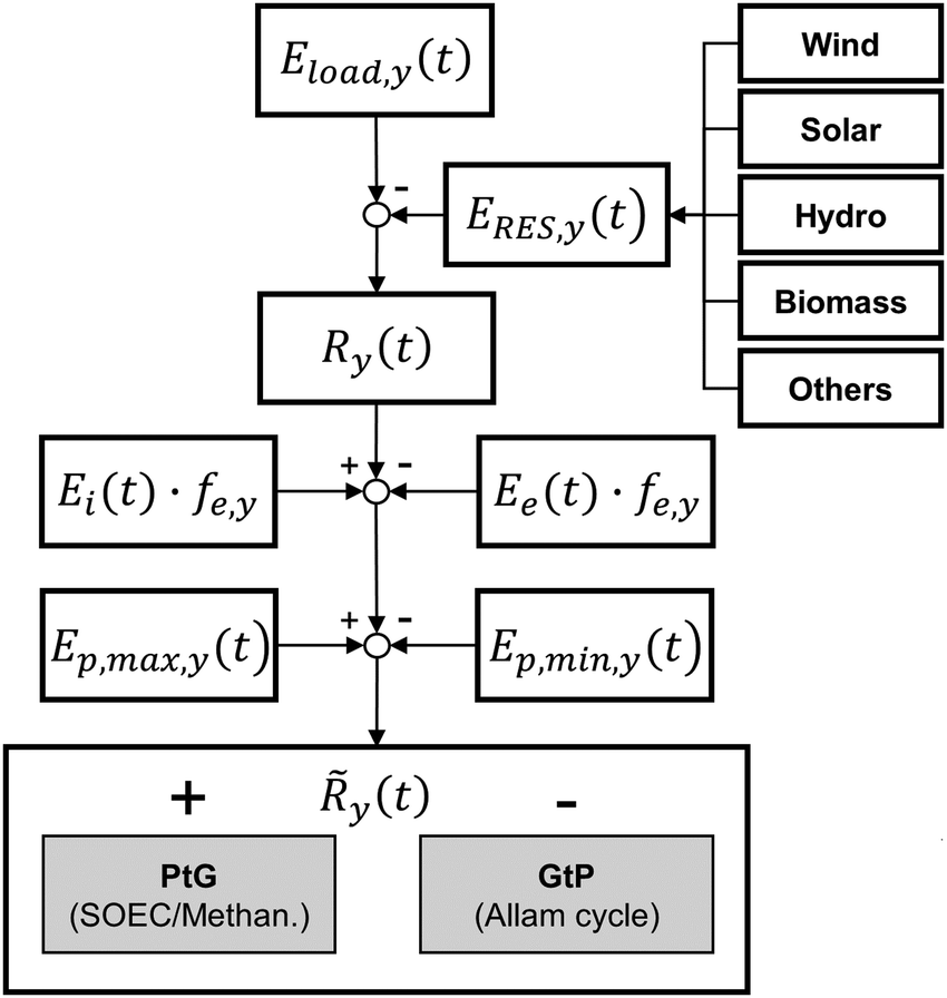
The energy storage plant consists of two sections: power to gas (PtG), and gas to power (GtP). As their operation is asynchronous, large-scale storage of both CH4 and CO2 is required (Fig. 1). Due to the confined technical use of CO2 and CH4 in a closed loop, the energy storage plant is characterised by no directly associated atmospheric emissions of both gases.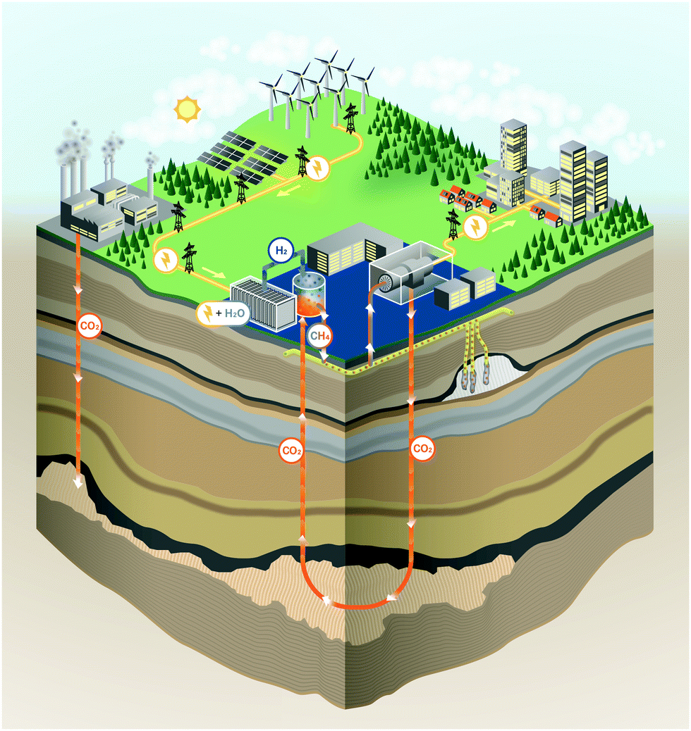 | ||
| Fig. 1 Carbon loop of the energy plant based on subsurface gas storage. | ||
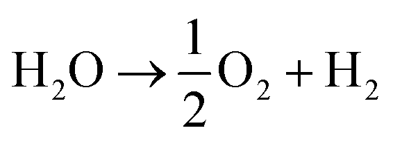
During periods of negative residual load, while renewable production exceeds the current load requirements of the energy system, the produced electricity is used in the PtG section, consisting of a water electrolyser coupled with a methaniser to produce H2 and subsequently CH4 according to eqn (1) and (2).
 | (1) |
| CO2 + 4H2 → CH4 + 2H2O | (2) |
| 2H2O + CO2 → CH4 + 2O2 | (3) |
During times of positive residual load, while the load requirements of the energy system exceed the current renewable electricity production, CH4 is extracted and burnt in the GtP section according to eqn (4).
| CH4 + 4O2 → CO2 + 2H2O | (4) |
Considering this circular approach to a carbon inventory of fixed size and to a fully decarbonized national energy system, it is apparent that, besides the large capacities for renewable energy production and electrolysers, large storage capacities for CO2, CH4 and O2 as well as for the intermediate appearance of H2 is necessary. Furthermore, H2 storage becomes necessary for other applications (e.g. steel production, chemical industry, refuelling infrastructure). Possible solutions for gas storage are discussed in Section 3.4. The flow chart for the investigated system structure based on an SOEC and a power cycle employing sCO2 as a working fluid is shown in Fig. 2.
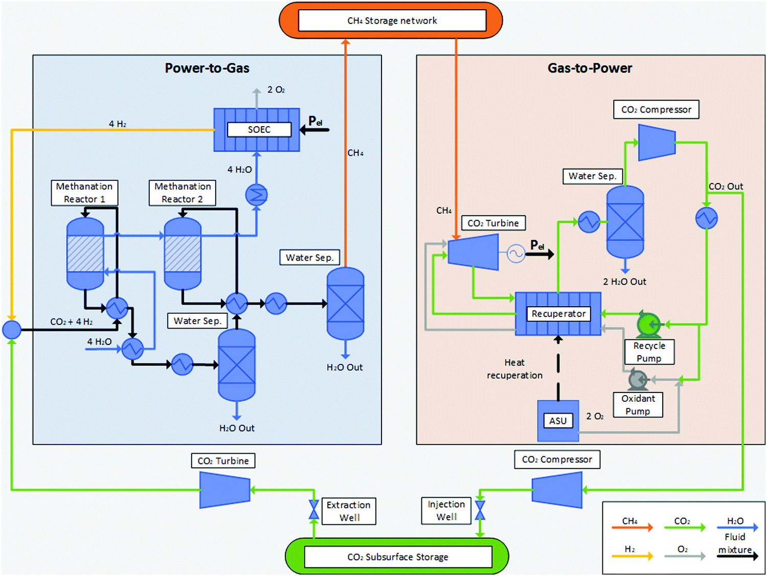 | ||
| Fig. 2 Flow chart of the combined PtG–GtP and subsurface storage energy plant. | ||
3.2 Power to gas cycle
Since the production of H2 from renewables within a fully decarbonised national energy system is widely regarded as the main contributor of the consumption of electricity, the choice of the respective electrolyser technology has a major impact on the overall efficiency of a PtG–GtP-system.41 A brief comparison of different electrolyser technologies is carried out in Table 1.| AEL | PEM | SOEC | |
|---|---|---|---|
| Development state | Commercialised | Demonstration/commercialised | R&D |
| Electrolyte | NaOH, KOH | Polymer | Ceramic |
| Charge carrier | OH− | H3O+/H+ | O2−/H+ |
| Cell temperature in °C | 40–90 | 20–100 | 600–1000 |
| Cell voltage in V | 1.8–2.4 | 1.8–2.2 | 0.91–1.3 |
| Efficiency HHV in % | 50–60 | 55–82 | 40–86 |
| Current system power consumption in kW h N−1 m−3 H2 | 4.5–7 | 4.5–7.5 | 2.5–3.5 |
| Part load capability/transient operation | Part load operation possible; not well suited for transient operation | Partial load and overload operation possible; well suited for transient operation | Transient operation not viable |
Solid oxide electrolyser cells (SOEC) gained major attention in recent years.50–52 Making use of a membrane electrode assembly (MEA) comprising dense ceramic electrolytes that can be either oxygen-anion or proton conducting as well as porous cermet electrodes, SOECs can produce wet or dry H2 at temperatures between 500 °C and 1000 °C.52–54 SOECs surpass todays commercialised electrolyser technologies such as AEL and PEM with respect to cell voltage, efficiency and specific power consumption (Table 1). However, the main advantage of SOECs lies in the thermal integration of downstream waste heat streams into the process, which is of particular interest and benefit in conjunction with process combination presented in this work. The employed Allam cycle offers waste heat at high temperature levels, which can be used within the SOEC stage. This leads to higher system efficiencies, especially when combined with downstream chemical syntheses such as methanation or methanol synthesis.55–59 The obtainable efficiency of SOECs incorporating thermal integration depends on a wide variety of factors, such as the composition or characteristics of the employed ceramic as well as the operating parameters of the SOEC stack. Considering heat recovery, electrolyser standalone efficiencies up to 90% and even close to 100% can be achieved.41,60
The most common technology for the synthesis of CH4 is the thermocatalytic conversion of H2 and CO2via the Sabatier reaction eqn (2). The thermocatalytic methanation by means of an evaporation-cooled polytropic fixed-bed reactor has reached the stage of industrial applications (TRL 9) so far and is currently assessed in large scale demonstration plants.23,42,61 Several research activities focus on a direct and thermally integrated coupling of SOECs and methanation reactors. Their focus lies on the reuse of the steam generated in the cooling system of the Sabatier reactor as feed stream in the SOEC stage. The rather low temperature of steam (approx. 250 °C) offers no suitable heat source for gas pre-heating through the implementation of additional heat exchangers, but can be used to replace dedicated water evaporators for the SOEC feed. Based on demonstration scale experiments, Gruber et al. showed overall PtG efficiencies up to 82% using this kind of thermal integration.59 Theoretically, efficiencies up to 86% can be achieved for the PtG process based on methanation.60,62
3.3 Gas to power cycle
The conventional power generation cycle compensates positive residual loads in case of insufficient renewable electricity production. Three possible routes are considered for the power generation in the present study as shown in Fig. 3. The state-of-the-art technology (Fig. 3a) is a conventional gas power cycle with post combustion carbon capture. Air and the synthetic CH4 are combusted to drive an open gas turbine cycle. The exhaust gas stream transfers the heat to a bottoming cycle to utilize the remaining thermal energy. From the exhaust gas stream CO2 is separated, which can be done for example via scrubbing. In case of the two other routes, CH4 and O2 will be used in an oxy-combustion process to drive the power cycle directly or indirectly. The O2 can be generated by an air separation unit (ASU) or from an O2 storage, which was initially filled by the electrolysis (Fig. 3b and c). The exhaust gas stream consists of H2O and CO2. A separation of CO2 requires less energy compared to the conventional process, since the H2O can be removed by condensation.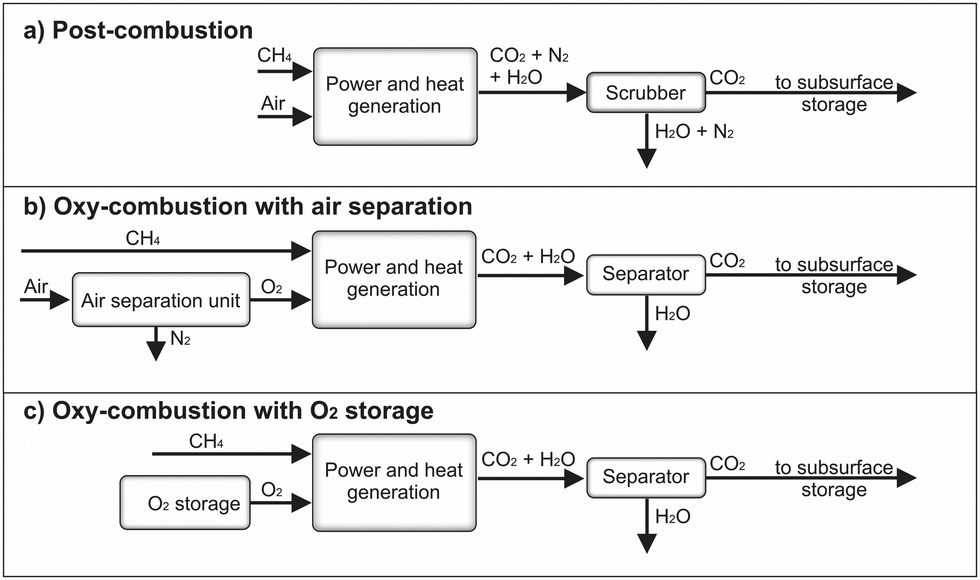 | ||
| Fig. 3 Process routes for heat and power generation including CO2 separation. | ||
Gas-fired power generation contributes to 23% of the overall power generation worldwide, mostly using CH4 as fuel.63 Gas turbines have become the preferred power generation technology due to their high cycle efficiency, small installation time, and low level of CO2 emissions compared to other conventional alternatives.64 There are several technical concepts of gas turbine power cycles, such as the simple gas turbine process, the steam injected gas turbine process, the humid air turbine process as well as the combined gas and steam turbine process. Due to the high process efficiency, the latter is the state-of-the art nowadays. Thus, it is analysed in more detail below.
The synthetic CH4 is injected with pressurized air into a combustion chamber. The combusted gas mixture drives a turbine with an inlet temperature up to 1500 °C and reduces down to 500 °C during expansion.65 The exhaust gas stream from the gas turbine outlet transfers the thermal energy to a water/steam based power cycle, also known as bottoming cycle, and is released to the environment. The evaporated water drives a steam turbine, condenses at the turbine outlet and is recirculated to the exhaust-water heat exchanger. The optimization of these cycle configurations is subject of several investigations.66–68
An upcoming alternative for the bottoming cycle is a thermal power cycle using sCO2 as a working fluid. Numerous studies have shown that sCO2 based power cycles have the potential to achieve higher cycle efficiency compared to conventional steam Rankine cycles.37,38 A higher power generation efficiency will eventually result in higher power-to-power efficiency and lower cooling water usage. Furthermore, the high density of the working fluid leads to small equipment size and footprint of the power generation unit. There are several possible sCO2 power cycle layouts, such as recuperation, intercooling, reheating and recompression. A more detailed investigation of the existing layouts can be found in ref. 69–71.
The sCO2 power cycles benefit from the fluid properties of CO2. For instance, a lower pressure and temperature near the critical point strongly reduces the required compression work and enhances the cycle efficiency. A comparison in between these two cycles based on system analysis shows a higher efficiency of the sCO2 cycle, when the turbine inlet temperature exceeds approximately 425 °C, which is the case for a gas turbine exhaust stream or the exhaust stream of a combustion chamber.72 Summarizing, sCO2 power cycles are promising technologies to convert chemical energy into electrical energy.71,73
The described cycles achieve a high thermal efficiency within the existing power plant technologies.64 Nevertheless, additional expensive, efficiency-reducing equipment is required in order to capture CO2 and other pollutants from the exhaust gas stream. This separation equipment reduces the overall efficiency and increases the cost of electricity by 50% to 70%.74 As a result the power cycle efficiency will be between 47.7% and 48.8%.75
The semi-closed direct heated, oxy-fuel Brayton cycle offers some advantages over the indirect heated closed Brayton cycle. In the former, the working fluid consists only of CO2 and H2O, due to the oxy-combustion. Due to a pressure below the critical point, CO2 is not in its supercritical phase. The separation of CO2 and H2O after expansion requires less energy and avoids the emission of NOx. CO2 or H2O are recirculated and used as moderator gas in the combustion chamber, leading to a reduction of the turbine inlet temperature. The efficiency of these oxy-combustion power cycles and the CO2 separation is between 48.9% when an air separation unit is taken into account and 53.6% without air separation unit.76,77
A power cycle using sCO2 as a moderator gas is also known as Allam Cycle. In such a cycle, the recycled CO2, CH4 and O2 enter a combustion chamber and the temperature increases up to 1150 °C at 300 bar pressure during combustion. The sCO2 and H2O gas mixture expands to 30 bar and 700 °C in the turbine. The exhaust flow enters a recuperating heat exchanger to preheat the high-pressure CO2 recycle stream. From this recuperator, the exhaust gas is cooled to near ambient temperature and water is separated. The remaining CO2 stream is recompressed to 300 bar and approximately 5% of the pure CO2 is exported to the subsurface storage. The remaining CO2 flow is cooled, partially mixed with O2, and pumped through the recuperator to reheat by the hot turbine exhaust gas flow. This preheated gas mixture enters the combustion chamber and the process repeats.78 The energy required for the ASU to generate the O2 was taken into account and the power cycle achieves an efficiency up to 59.8% at low capital cost.79 However, if it is possible to supply the power cycle with stored O2 provided by the electrolysis section, an increase of the net cycle efficiency to 66.1% can be achieved.80
Table 2 shows a comparison of the previously described power cycle technology choices and the achievable roundtrip efficiencies for the PtG–GtP system based on a PtG efficiency of 82% as shown in ref. 59. The PtG–GtP system paired to an Allam cycle with dedicated O2 storage is characterised by a maximum roundtrip efficiency of 54.2% whereas the same configuration with a separate ASU reaches roundtrip efficiencies of up to 49.0%.
| Cycle | Combustion | Working fluid sCO2 | GtP efficiency (%) | Ref. | PtG–GtP efficiency (%) |
|---|---|---|---|---|---|
| Combined cycle | Post-combustion | No | 50.0–50.7 | 66–68 | 41.0–41.6 |
| Combined cycle | Post-combustion | Yes | 50.0 | 71 and 73 | 41.0 |
| Combined cycle | Oxy-combustion | No | 48.0–49.3 | 68, 75 and 76 | 39.4–40.4 |
| Allam cycle with ASU | Oxy-combustion | Yes | 55.1–59.8 | 75, 76, 78–80 | 45.2–49.0 |
| Allam cycle | Oxy-combustion | Yes | 66.1 | 80 | 54.2 |
The PtG–GtP efficiency is also known as round-trip-efficiency and commonly applied for energy storage systems. Furthermore, the cost in terms of capital expenditures of storage technologies is a relevant parameter for their economic evaluation. In order to rank the presented long-term energy storage system, data from literature were analysed and listed in Table 3.
As one can see, the pumped hydro storage is a well-developed technology, which reaches high efficiency at low cost and can be considered as a reference case. However, the potential locations for installation of pumped hydro storages are limited and further storage technologies are required. In the study of Abdon et al.,33 the long-term storage of H2 would require large capacities, which cannot be provided by technical storages. Thus, an injection of H2 into the gas grid (to limited extent) as well as a reformer to convert the gas mixture was considered. As a result, a power-to-CH4 storage achieves higher efficiencies and lower cost compared to a power-to-H2 storage system. On the other hand, Jülch81 studied a cavern storage for both, H2 storage and CH4 storage. Here the CH4 storage was considered to be approximately 3 times more expensive, without cause. Furthermore, additional cost for a CO2 purification plant were considered for the power-to-CH4 storage system, which is not needed in the presented energy storage concept. It becomes clear, that the presented energy storage system achieves higher efficiencies and does not require additional gas reformers or CO2 purification. Furthermore, the geothermal energy input into the stored CO2 may enhance the methanation process efficiency. Hence, potentially lower costs at higher efficiencies can be expected for the presented concept. Though efficiency and cost are crucial parameters for evaluating various storage technologies, other parameters such as energy density, reliability, lifetime and storage capacity are also relevant. Thus, for determining the optimum storage technology several aspects need to be considered, specifically thorough techno- and thermo-economic analyses. Therefore, a thermo-economical investigation will be conducted in subsequent studies.
3.4 Gas storage options
Gas storages can be categorised in: (i) subsurface stores based on natural and artificial underground structures, such as porous aquifers or salt caverns and depleted oil and gas reservoirs, and (ii) technical gas storages, such as pressurized tanks or cryogenic storage of liquefied gases. The previously discussed PtG–GtP technology options require large storage capacities for CH4 and CO2. Hence, technical storages for CH4 and CO2 lie outside the scope of this study. Due to the expected asynchronous operation of the process steps of the PtG–GtP plant and further operational cases, such as start-up, shutdown and component failure, additional gas storages are vital to the overall plant design, with other relevant gases being O2 and H2.Cavern and aquifer storages differ with respect to their geological and limiting availability as well as their development and operational cost. Typically, caverns offer faster rates of gas deliverability, and an increased number of injection–extraction cycles per year. However, caverns require a larger initial capital investment for their development, typically multiple years of leeching, as well as water treatment for the produced water during the leeching process. The costs associated with temporary aquifer storage development involve large data acquisition and geological characterisation as they have not been previously explored for use. Aquifer stores require large amounts of cushion gas (up to 90% of overall volume), which could however be seen as an opportunity here to unload an initial amount of CO2 outside of the synthetic fuel loop. Finally, a significant amount of water is also expected within porous aquifer development and operation, which will need to be cleaned and disposed of at cost. Depleted oil and gas fields, while only available at a handful of locations, offer reduced costs compared to porous aquifers due to their previous use which reduces the costs associated with characterisation and water production.82
Finally, surface storage of gas is also well established through either storage in tanks of liquefied natural gas (LNG) or overloading the pipeline network itself with increased gas pressure. The amount of gas that can be stored in surface stores is however notably lower than their underground counterparts.
Recoverable CO2 storage presents a different but nonetheless related set of geological requirements to permanent CO2 storage in porous rock. While in both cases, the existence of a thick, high porosity storage layer sealed by a low permeability barrier layer directly overhead is vital, the necessity of a well-formed structural trap is less important in the permanent storage case, as the injected CO2 is expected to form a considerable areal plume within the storage layer without any prospect of recovery. Finally, permanent CO2 storage is mostly done in deep (>800 m) layers in which CO2 reaches a supercritical state due to the favourable pressure–temperature environment at such depths, ensuring greater injectivity while reducing hypothetical interaction with shallower layers.
In Germany, a large potential for permanent CO2 storage has been identified90 and many potential stratigraphically successive storage-seal pairs have been located with sufficient thicknesses across the onshore and offshore territory.91 The overall onshore and offshore storage potential in Germany has been estimated to lie between 20.4 and 115.3 gigatons of CO2. A summarising map of the onshore CO2 storage potential can be seen in Fig. 4 (left). The data originates from a study and data release by the German Federal Institute for Geosciences and Natural Resources.90 This map was established by joining the various surface zones that bear storage-capable layers meeting a series of geological criteria. This map layer is labelled “Permanent storage”. Zones that bear shallower storage-capable layers with less stringent criteria were similarly joined in a single map layer shown as “Temporary storage”.
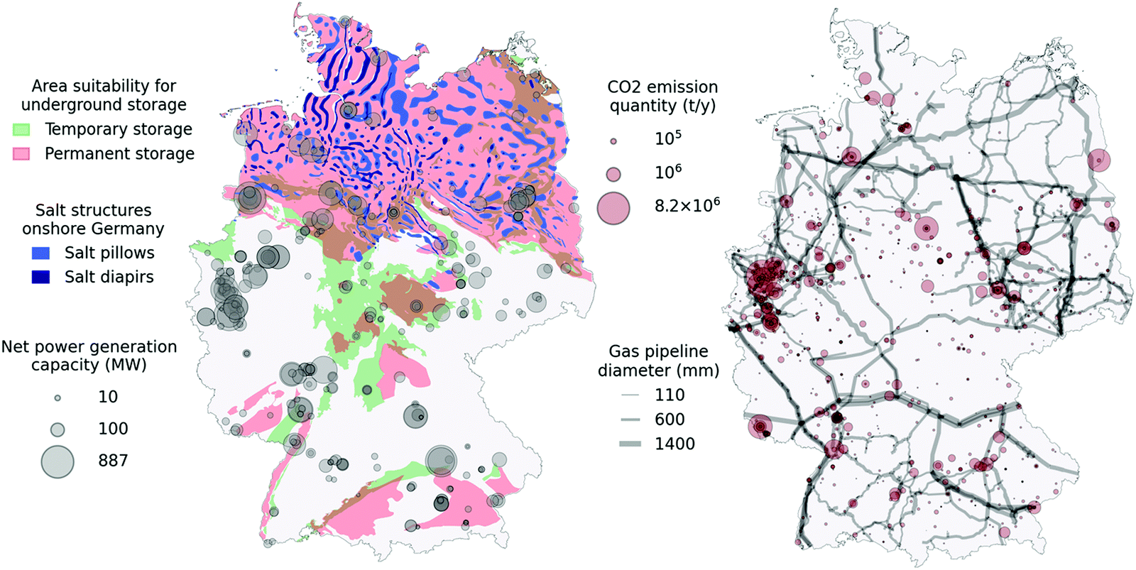 | ||
| Fig. 4 Map showing relevant underground storage potential for salt structures and porous rocks. Point sources showing quantities of emitted CO2 registered within the ETS are shown as grey circles. | ||
Temporary storage zones are shallower than permanent storage zones and have a depth of less than 800 m. This depth roughly marks the transition of stored CO2 from a gas to a supercritical state. For that reason, CO2 possesses lower density and buoyant forces reduces injectivity and CO2 might remain closer to the injection location and can be more easily recovered. In both cases, the porosity of storage rocks must be above 10%, and average permeabilities above 10 mD, while often being higher. Storage rock thickness must be at least 10 m. The permanent storage layers must furthermore have a storage rock upper depth of at least 800 m and a barrier rock thickness of at least 20 m. Well-established low permeability rocks, such as salt and clay layers, were considered as barrier rocks. A pre-requisite for any use of the underground is in-depth local geological characterisation to establish safe operation. Further geological characterisation may reveal new knowledge regarding the underground storage potential and as such these maps are subject to change. While a large portion of the German onshore territory is covered by potential storage zones, areas devoid of deep storage capacity are observed, notably in North Rhine Westphalia, in which most existing power plants are found.90
The same map (Fig. 4, left) shows the identified salt structures that could potentially sustain salt caverns for temporary CO2 storage.92 Salt caverns are artificial cavities created by dissolving solid underground salt layers with freshwater. As such, the process is only feasible in specific salt formations. In Germany, the Zechstein formation, currently largely unused, provides ample possibilities for salt caverns, achieving sufficient thickness in large areas spread over most of the Northern half of Germany, with the inclusion of very thick salt diapirs in the Northwest region. There are currently 31 cavern storage facilities comprising a usable volume of 27.4 billion N m3. According to some estimates, German cavern storage potential accounts for up to 42% of all European storage potential.93 Salt caverns are currently used for temporary storage of high value gases such as CH4 due to the high initial investment costs.
Finally, gas-fired power generation facility locations and corresponding net power generation capacity for the year 2020 are displayed.94 Through this map, we can get an impression of good candidates for our system concept displaying high power generation capacity and storage potential at the same location. On another map (Fig. 4, right), CO2 emitters originating from industry and registered within the European Trading Scheme (ETS) for the year 2018 are shown as translucid red circles.95 Emitters whose primary function is energy production are not included in this map. Instead, harder-to-abate industry sources are shown as potential to supply the proposed plant concept with CO2 specifically for the compensation of potential losses during the system operation. The 2020 gas pipeline network96 (showing pipelines with diameters above 100 mm) is also given, indicating CO2 pipeline network layout possibilities linking industry sources to plant or storage locations. Overlapping pipelines appear darker as individual pipelines are drawn with some transparency.
Furthermore, a basic energetic assessment was done in order to evaluate the input of the geothermal temperature and pressure within a deep porous storage. The temperature as well as the pressure inside the geological structure strongly depends on its depth. The sCO2 leaves the power cycle at a pressure of 100 bar and a compression is not required for storages at shallower depths than 1000 m. In case of deeper storage of e.g. 5000 m the sCO2 needs to be compressed and will be heated in the process. Therefore, a thermal storage will be beneficial before the CO2 is stored in the underground. Since the temperature of the geological structure is at approximately 180 °C, the CO2 will be heated during the storage. As the CO2 is released form the underground storage and flows towards the methanation process, an expansion turbine utilizes the volumetric work. The CO2 is preheated by the thermal storage and less heating energy is needed for the methanation. In fact, a deeper storage is beneficial, since the geothermal heat can be utilised and the process efficiency increases. Such combination of geothermal energy production with supercritical CO2 injections has been investigated elsewhere.97,98 Nevertheless, the additional equipment cost for compressor, thermal storage and the turbine need to be considered in subsequent studies. Therefore, further studies will investigate the energetic assessment of the storage from a thermo-economical perspective.
Technical storage of O2 is typically carried out using high-pressure cylinders, tube trailers or large spherical tanks for stationary applications, depending on the required frequency and rate of consumption. For larger needs like the ones expected in the discussed PtG–GtP system, cryogenic storage of liquid O2 is a relevant storage option. Yet still, the scale of the required cryogenic equipment and number of storage tanks within in one single plant location is expected to far exceed typical O2 storage sites in operation today. To circumvent the previously laid out problems, the storage volume per site could be limited and the bulk of the required O2 for the oxy-combustion process could be provided by a separate ASU as shown in Table 2 in Section 3.3.
Hydrogen storage is necessary if the electrolyser and the methanation process cannot be coupled perfectly or if additional H2 is extracted from the PtG cycle for other applications, such as steel production, chemical industry and mobility. However, as H2 storage is not a central element of the analysed storage power plant concept and is only needed in smaller quantities, any details on respective storage technologies will be omitted.
4. Forecast study: Germany 2050
4.1 General information
The German action plan to achieve greenhouse gas neutrality by 2050 is based on significantly and permanently reducing energy demand, using renewable energy in all sectors, and efficient use of electricity from renewable energy sources in heat provision, transport, and industry.100 Over the past years, the production of renewable electricity in Germany has grown substantially. Its share of the annual net total increased from 30.2% to 43.9% between 2015 and 2019.According to the energy transition plan of the German government, renewable energy sources are expected to cover at least 65% of the electricity production in 2030, and 80% in 2050.101 These goals require the installation of large amounts of generation capacity, namely as photovoltaic panels and wind turbines. The volatility of these technologies calls in turn for the large-scale implementation of energy storages to maintain a reliable supply of electricity.
One of the main contributing factors influencing the national energy balance in 2050, aside from the installed renewable capacities will be the evolution of the overall electricity demand within the next decades. A wealth of different national studies attributed to the detailed future development of the energy system of Germany can be found elsewhere.102–105 This forecast employs a reference scenario that assumes a significant increase of the electricity demand in Germany until the year 2050. The overall electricity consumption in Germany (Fig. 5) will increase up to approx. 964 TW h by 2050 according to ref. 106.
 | ||
| Fig. 5 Net electricity consumption in Germany (left) and sector coupling demands in TW h for 2050 (right) according to ref. 106. | ||
Although the base consumption of electricity will remain the same until 2050, the consumption due to sector coupling effects (power to X (PtX), heat and transportation sector) will steadily increase. This reference scenario agrees with other recent national studies.107 Based on the electricity consumption forecast of the aforementioned reference study, an approximate projection of the German energy balance until 2050 based on electricity generation data of the year 2019 has been assessed.
4.2 Assessed scenarios
Since the proposed PtG–GtP system is based on the utilization of CO2 in a closed loop, this forecast aims to predict the amount of the required renewable capacities and the corresponding residual load profiles to enable a near-CO2-neutral system operation. This work assesses two different energy system scenarios for the year 2050 and their schematic representations are depicted in Fig. 6. | ||
| Fig. 6 Assessed energy system scenarios. | ||
In both scenarios (Fig. 6), the production of CO2 through the combustion process of the SNG-fired power plant is equal to the CO2 intake of the methanation process. In order to achieve this, while covering electricity demand at all times, sufficient capacities for both electrolysis and renewable electricity production have to be provided. The overall carbon inventory attributed to the plant operation remains constant and no permanent CO2 storage as well as no additional CH4 source is needed during system operation. Both scenarios represent a fully renewable energy system (100% renewable energy sources; RES) and the storage system is expected to solely cover the national energy demand at all times and the respective renewable generation capacities in each decade are chosen accordingly.
In the first scenario (Fig. 6a), O2 produced via electrolysis during times of negative residual loads is stored in a dedicated technical storage for later reuse in the GtP reconversion step. In contrast, the second scenario (Fig. 6b) makes use of an ASU for O2 supply during positive residual loads, requiring additional electrical power for its continuous operation. The excess O2 from the PtG process is expected to be sold and/or instantly used for other industrial processes. Apart from the different O2 supply, scenario 1 and 2 share the same boundary conditions.
The forecast is based on data taken from the SMARD platform of the German Bundesnetzagentur (which reflects the same data as the transparency platform ENTSO-E of the European Union).108 Employed data sets are time series of the net electricity generation, consumption and export/import flux in MWh as well as the installed generation capacities in MW for 2019. The forecast is carried out for the years of 2021 to 2050.
The required power installations for the electrolysis/methanation step as well as for the reconversion step have been determined. All assessed cases require the existence of a non-permanent subsurface CO2 storage. Moreover, the acquired forecast data is used for the subsequent analyses of the subsurface storage potentials and requirements of CH4 and CO2 as well as the technical storage of O2.
The scenarios presented in this work are intended as a basic orientation and an instrument to verify the plausibility of the combined subsurface gas and energy storage system with respect to the required storage capacities and renewable generation capacity on the national scale of Germany.
4.3 Renewable electricity production and load profiles
To obtain scalable renewable production reference data reflecting basic meteorological patterns and features, the net renewable production time series (ERES) were normalized to the installed capacity of each individual generation type of the respective base year (PRES) according to eqn (5).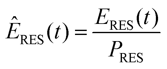 | (5) |
| ERES,y(t) = ÊRES·PRES,y | (6) |
| Capacity installed in GW (PRES) in 2019 | Expected annual growth in MW (ΔPRES) | |
|---|---|---|
| Biomass | 7.75 | 600 |
| Hydroelectric | 5.28 | 50 |
| Wind (offshore) | 6.39 | 1200 |
| Wind (onshore) | 52.79 | 4700 |
| PV | 45.30 | 10![[thin space (1/6-em)]](https://www.rsc.org/images/entities/char_2009.gif) 000 000 |
| Other | 0.49 | 50 |
The installed renewable capacity in the respective year was calculated using eqn (7) cumulating the annual capacity extensions (ΔPRES) until the forecasted year.
 | (7) |
| Eload,2050(t) = Eload(t)·fload | (8) |
 | (9) |
| Annual demand in TW h (eload,y) | |
|---|---|
| Base year | 2019 |
| Base year consumption | 485 |
| 2030 | 657 |
| 2040 | 813 |
| 2050 | 970 |
The aimed consumption of 964 TW h is exceeded in the base year 2019. The scaled load profiles were used for the subsequent calculation of the residual load profiles.
4.4 Residual load profiles and CO2 load curves
The national residual load profile (Ry) has been defined as the difference between the scaled load time series (Eload,y) and the scaled net renewable electricity production time series (ERES,y).| Ry(t) = Eload,y(t) − ERES,y(t) | (10) |
The transmission capacities of export and import with neighbouring countries will most likely increase in the upcoming decades.109 Thus, this forecast includes smoothing of the residual load profiles during peak loads via import and export. To implement this, time series for imported (Ei) and exported (Ee) amounts of electricity have been included in the model. They are based on the physical net flux of import and export with all neighboring countries of Germany in the respective base year. To reflect the increase in transmission capacities, the import and export time series have been linearly scaled expecting an increase by 50% until the year 2050 (fe,2050= 1.5). Furthermore, additional peak load capacities were introduced for both scenarios to account for other forms of grid flexibility resources, which, in fact, will coexist with the proposed PtG–GtP plant. The peak load capacities (Ep,max & Ep,min) will reach a value of 30 GW in 2050, and increase gradually over the course of the forecasted period. Residual load smoothing via pumped hydroelectric storage was not considered. All measures with respect to residual load smoothing are reflected in eqn (11).
![[R with combining tilde]](https://www.rsc.org/images/entities/i_char_0052_0303.gif) y(t) = Ry(t) + (Ei(t) − Ee(t))·fe,y + Ep,max,y(t) − Ep,min,y(t) y(t) = Ry(t) + (Ei(t) − Ee(t))·fe,y + Ep,max,y(t) − Ep,min,y(t) | (11) |
 | ||
| Fig. 7 Applied methodology for the calculation of residual load profiles. | ||
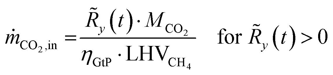
The resulting residual load profiles are combined with a simple model of the energy plant to specify the demand and the output of CO2 attributed to processing and subsurface storage. According to Gruber et al., the overall efficiency of a coupled process comprising high temperature electrolysis and a downstream catalytic methanation with close heat integration can reach system efficiencies of up to ηPtG = 82%.59 During times of negative residual loads, the system produces H2 through the SOEC with an immediate downstream synthesis of CH4. The SOEC model assumes a constant operation at a cell voltage of φSOEC = 1.3 V. The required amount of CO2 retrieved from the subsurface storage (ṁCO2,out) is calculated based on the H2 output of the SOEC (Faraday's law) and the stoichiometry of the methanation reaction (eqn (2)) according to eqn (12).
 | (12) |
 | (13) |
| |ṁCO2,out − ṁCO2,in| ≤ 0.001 | (14) |
5. Results
5.1 Scenario 1: O2 storage
To match the CO2 demand of the PtG process and the CO2 output of the GtP process in the year of 2050 and thus reaching full circularity, the required annual renewable capacity extensions need to be increased compared to the initially expected annual growth rates according to ref. 107 (Table 6).| Expected annual growth in MW107 | Required annual growth in MW | |
|---|---|---|
| Biomass | 600 | 741 |
| Hydroelectric | 50 | 62 |
| Wind (offshore) | 1200 | 1482 |
| Wind (onshore) | 4700 | 5804 |
| PV | 10000 |
12348 |
| Other | 50 | 62 |
To reach a 100% renewable electricity generation in Germany in 2050, 30.1 GW of biomass, 52.2 GW of offshore wind, 227.5 GW of onshore wind and 416.9 GW of PV capacity must be installed and a total annual renewable capacity growth of 20.5 GW has to be maintained beginning in 2021. The total installed renewable generation capacity would have to rise from 118 GW in 2019 to approx. 736 GW in 2050 (Fig. 8).
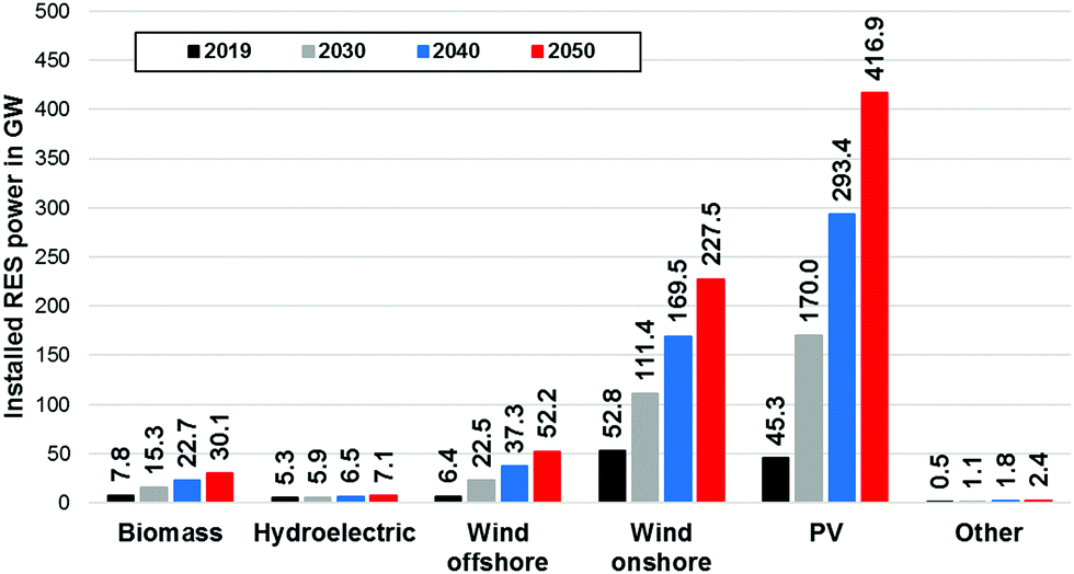 | ||
| Fig. 8 Simulated renewable installations in 2030, 2040 and 2050 for scenario 1. | ||
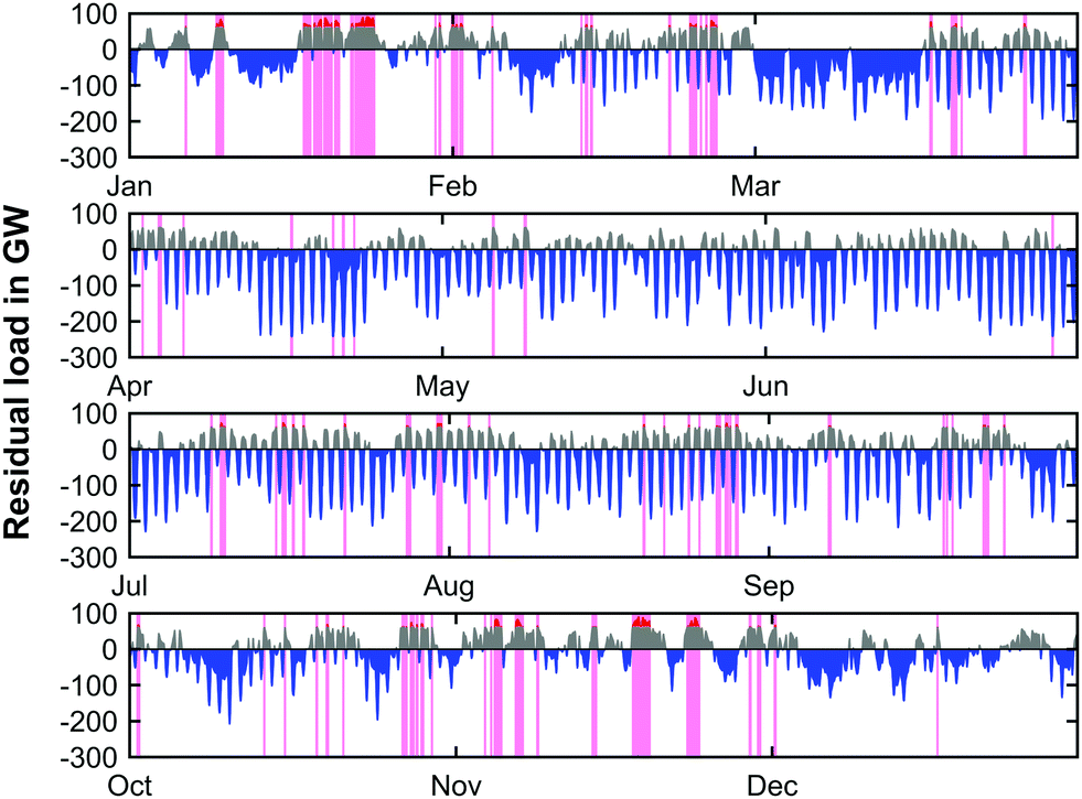
Due to the forecasted amount of installed renewable capacities in 2050, the residual load profiles are significantly distorted with respect to their power amplitude in comparison to the current state. Fig. 9 shows the residual load profile over the course of the year 2050 for the base year of 2019.
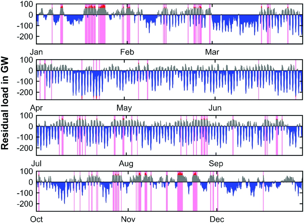 | ||
| Fig. 9 Simulated residual load profile (2050) with PtG operation (blue; negative residual load), GtP operation (grey; positive residual loads) and peak residual load management (red) for scenario 1. Pink vertical streaks indicate presence of peak residual load management. | ||
It is evident that the main part of the load can be directly provided by renewable sources, and that renewable electricity production will exceed conventional electricity production by far. However, there are still sustained times during the year characterized by positive residual loads. This means periods of insufficient renewable electricity production and the need for conventional production capacities. Moreover, the residual load profile shows high frequency oscillations, especially during the summer months. This is due to the increased photovoltaic electricity generation caused by the high PV installation capacity and increased sun exposure during daytime. The highest values during positive peak load times appear predominantly during winter. In 2050 the maximum peak load would be 92 GW. On the contrary, the negative peak powers occur during the summer months and a minimum residual load of −264 GW can be observed. Since fixed capacities for peak residual load management were employed, the capacity of the GtP process (positive residual loads) and the total required electrolysis capacity for the PtG process (negative residual loads) can be derived from Fig. 9 on the national scale of Germany. The required electrolysis power installations would have to be as high as 234 GW in 2050 whereas the installed capacity for the power generation cycle would have to be 62 GW. Thus, the required electrolysis capacity exceeds the respective capacity of the GtP step by a factor of approx. 4.
The CO2 load profile (Fig. 10) clearly reflects the same oscillatory behavior as the residual load profile. The maximum charge and discharge rates of CO2 range from −18.5 to 30.3 kilotons per hour. To further elaborate the characteristics of the energy production, the annual load duration curves for the years 2019, 2030, 2040 and 2050 are shown in Fig. 11.
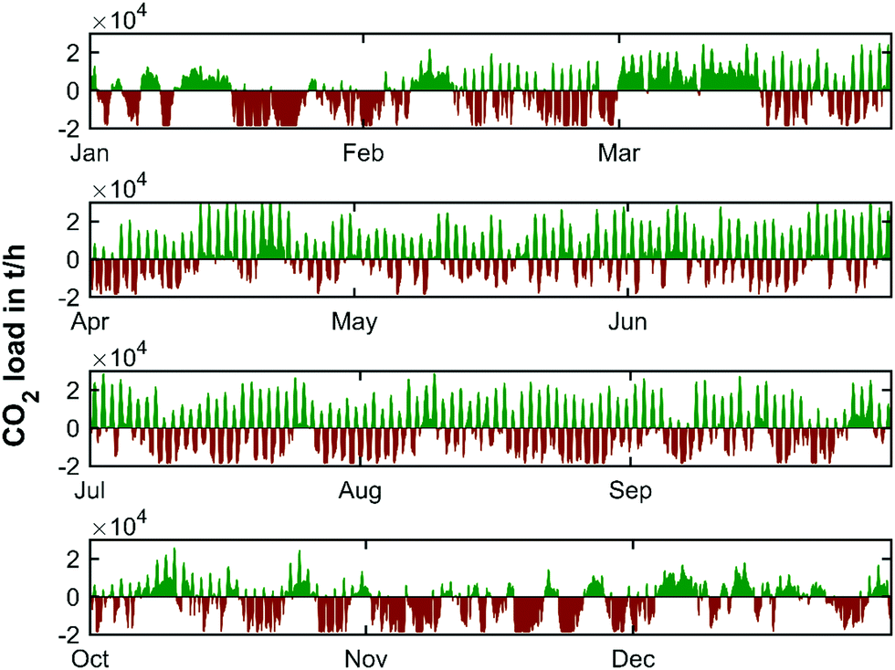 | ||
| Fig. 10 Simulated CO2 load profile (2050) for scenario 1. | ||
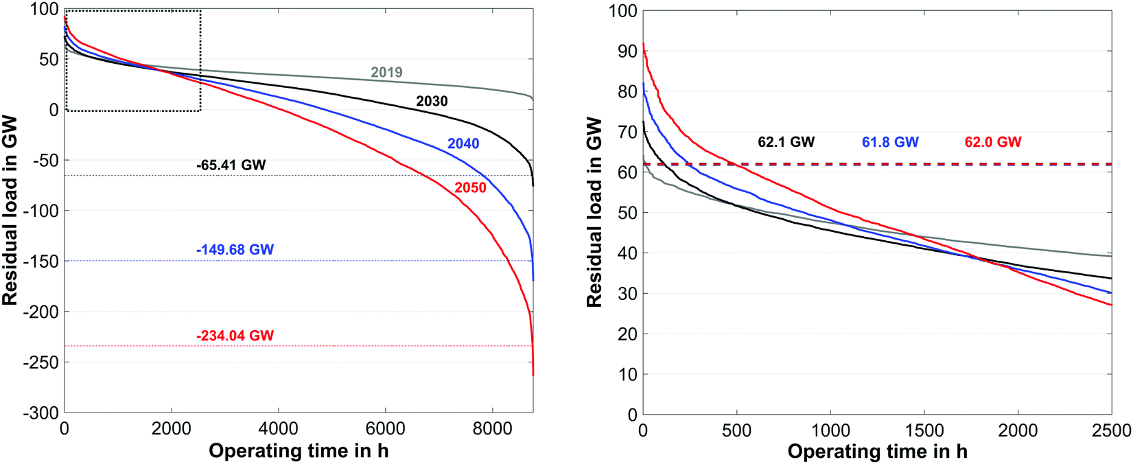 | ||
| Fig. 11 Annual load duration curve for the years 2019, 2030, 2040 and 2050 based on the reference data of 2019 (left) and detailed view (right). | ||
Because of the steady increase of renewable production capacities, the periods with negative residual loads show a distinct increase over the forecasted time span. As it can be seen in Fig. 11 electrolysis capacities of 66 GW, 150 GW and 234 GW must be installed before the end of 2030, 2040, and 2050 respectively. The required electrolysis power could be reduced through the introduction of additional peak load storage capacities during times of negative residual peak loads. In contrast to this, the required conventional production capacities remain unaffected (62 GW) over the course of the forecast window, provided that sufficient peak load capacities are available each year. A summary of the overall energy balance of the PtG–GtP system for the forecasted year of 2050 based on the reference year 2019 can be found in Table 7.
| Reference year | 2019 |
| Renewable capacity (total) in GW | 736 |
| Load in TW h | 970 |
| Renewable production in TW h | 1200 |
| GtP production in TW h | 140 |
| PtG demand in TW h | 323 |
| Net export in TW h | 51 |
| Net peak load cut-off in TW h | 4 |
| Renewable production to load ratio (—) | 1.22 |
To allow for a near carbon-neutral system operation under the presented boundary conditions, the installed renewable capacity as well as the amount of electricity produced by renewables must exhibit a substantial increase in the upcoming decades. The total electricity produced by renewable sources in 2050 will be 1200 TW h with installed production capacities of 736 GW. The ratio between the renewable production and load is found to be 1.22, meaning that in a 100% renewable energy system, renewable production will exceed the respective consumption. It becomes clear that the presented scenario requires entirely different future renewable generation capacities than the current national energy strategy of Germany considers (see Section 4.1). The amount of conventional electricity production will be exclusively provided by SNG-fired Allam cycle power plants and is reduced to approximately 50% compared to the base year production value. The annual electricity demand for the PtG step equals 323 TW h in the year 2050.
The smallest storage volume is found so that the storage site is never over- or under-capacity. This is given by the maximum value at the peak of the CO2 curve added to the absolute value of the (negative) trough of the cumulative CO2 curve. Matched here to the cumulative CO2 curve obtained from the yearly weather pattern of 2019, this represents a characteristic storage quantity of 10754 kilotons of CO2. The yearly charging cycle of the temporary storage of CO2 in this scenario is displayed in Fig. 12 (top).
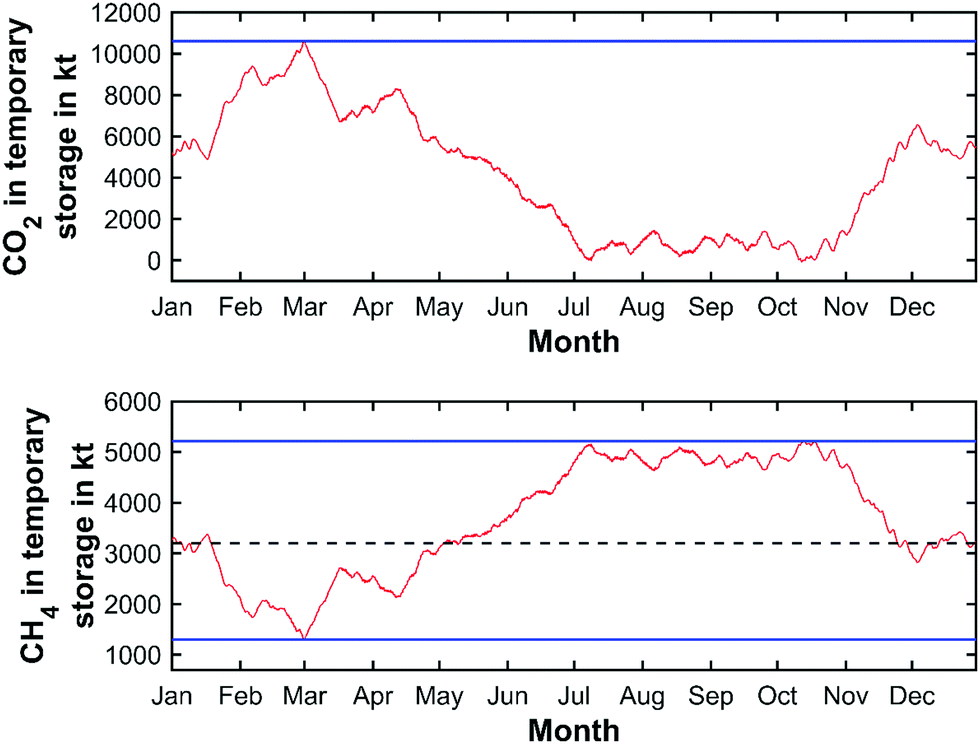 | ||
| Fig. 12 Cyclical charging and discharging of CO2 and CH4 storage on a national scale (the upper blue lines indicate the storage capacities required; the lower blue line indicates the minimum storage quantity of CH4 and the dashed black line represents the average stored quantity of CH4 in the subsurface storage based on the chosen initial storage value). | ||
The concept proposed in the paper applies to a single localised power plant. It can be therefore expected that for a single plant location, the renewable energy availability and corresponding CO2 load curve is tied to the renewable capacity in the vicinity of the plant. It is assumed that 20 equivalent plants will share the CO2 load curve equally. For each plant, the corresponding regional CO2 load curve is then the national load curve divided by a factor of 20. Regional differences in weather patterns and renewable energy capacity are also expected to create regional CO2 load curves that differ. These differences are not considered in the current study.
At typical salt cavern depth of 800 meters, geostatic pressure is approximately 170 bars and temperature is of 34 °C,110 CO2 reaches a density of 843.73 kg m−3,111 leading to a characteristic cavern geometrical volume for CO2 of 637290 m3 (271.6 million N m3). This value, with an added cushion volume of 30%, represents approximately the upper limit of a technically feasible cavern (∼1 million m3). Considering multiple caverns can be created and used in parallel for a single storage location, this value does not appear to be technically prohibitive. While using a large capacity individual cavern or a connected series of smaller caverns at each facility location may be technically feasible for certain regions, given the large salt cavern potential in northern Germany, this seems unfeasible in other German regions (see Section 3.4). Furthermore, high-value salt caverns maybe preferentially used for other types of gas storage rather than CO2. For this scenario, a porous storage option would be preferred, such as a disused oil and gas field or a porous aquifer, of which Germany has an abundance of potential, in which CO2 is injected and recovered via a geological trap.
Large-scale storage of high-value CH4 is however expected to be carried out solely via salt caverns. The yearly charging cycle for CH4 is shown in Fig. 12 (bottom). The characteristic maximum storage quantity is determined to be 5211 kilotons with an average CH4 quantity of 3200 kilotons and a minimum quantity of 1300 kilotons inside the salt cavern, based on the chosen initial storage value of CH4. Therefore, the required net storage quantity for CH4 is determined to be 3911 kilotons (equal to 54.5 TW h). Assuming an average cavern storage pressure of 200 bar at a temperature of approximately 30 °C, CH4 reaches a density of 152 kg m−3,112 the required net underground storage volume for CH4 is estimated to be approx. 25.8 million m3 (5.5 billion N m3) on the national scale. Adding the required cushion gas volume, a total storage volume of 36.9 million m3 (7.8 billion N m3) has to be held available nationwide. Considering the total available CH4 storage available in Germany today (27.4 billion N m393), the application of the circular power plant concept appears as a viable option for large-scale electricity storage in the future. Dividing the total storage requirements according to the previously mentioned number of operating sites, 1.9 million m3 (0.4 billion N m3) of storage volume have to provided at each site, leading to 2 maximum capacity caverns per plant location.
The storage quantity for O2 is retrieved in the same manner, leading to a total quantity of approx. 15650 kilotons to be stored. Since the charging and discharging of the O2 store exhibits the same temporal fluctuations as seen in Fig. 12, the respective diagram is not shown here. Assuming cryogenic and liquid storage at ambient pressure conditions and a maximum tank size of 1500 m3, a total storage volume of 13.7 million m3 or 9140 maximum size tanks (approx. 460 per plant site) has to be provided. A summary of the required storage capacities for all relevant gases/liquids can be found in Table 8.
| Gas | Storage quantity in kilotons | Storage volume in m3 | Storage volume in N m3 |
|---|---|---|---|
| CO2 (gaseous) | 10754 |
18.2 million | 7.8 billion |
| CH4 (gaseous) | 3911 | 36.9 million | 7.8 billion |
| O2 (liquefied) | 15650 |
13.7 million | — |
From a techno-economical and safety standpoint, the application of cryogenic O2 storage at the determined locational plant scale is not considered as a viable option for a potential and applicable system design.
5.2 Scenario 2: O2 provision via air separation unit
Since the previously presented scenario revealed challenging storage requirements with respect to the cryogenic storage of O2, the second scenario utilises an ASU instead of stationary O2 storage. Apart from the adjusted GtP efficiency of the Allam cycle reconversion step to 59.8%, no changes have been made to the forecast calculation. A comparison between the retrieved PtG, GtP and renewable capacites for both scenarios is tabulated in Table 9.| Scenario | Required PtG installations in GW | Required GtP installations in GW | Required renewable energy sources capacities installation in GW |
|---|---|---|---|
| 1 | 234 | 62 | 736 |
| 2 | 243 (increase: 3.85%) | 62 (increase: —) | 752 (increase: 2.17%) |
Due to the reduction of the efficiency of the reconversion step from 66.1% to 59.8%, the required renewable energy sources installation to meet a balanced CO2 load curve by 2050 exhibit an increase of 16 GW to 752 GW. To provide sufficient capacities for the production of CH4, the installed electrolysis capacity will have to be as high as 243 GW, exceeding the previously determined value by 9 GW. The required GtP capacities show no changes and remain at 62 GW. The simulated residual load profiles for the year of 2050 and the balanced scenario based on an ASU is shown in Fig. 13.
 | ||
| Fig. 13 Simulated residual load profile (2050) with PtG operation (blue; negative residual load), GtP operation (grey; positive residual loads and peak residual load management (red) for scenario 2). | ||
The residual load progression across the forecasted year based on the system with an ASU only shows minor deviations when compared to the progression of the system with O2 storage presented in Fig. 9. It can be noticed that the times where peak load management occurs (pink bands) is slightly reduced and hence the net peak load cut-off is lowered. Since the deviation of the CO2 load curve only exhibits barely noticeable changes, the respective data is not shown here.
The retrieved values for the required storage quantities of CO2 and CH4 are summarised in Table 10. Through the introduction of the ASU to the reconversion system and the lowered roundtrip efficiency, the required storage volumes for CO2 and CH4 are increased by 4.24% compared to the balanced scenario with O2 storage.
| Gas | Storage quantity in kilotons | Storage volume in m3 | Storage volume in N m3 |
|---|---|---|---|
| CO2 (gaseous) | 11210 (increase: 4.24%) |
19.0 million | 8.1 billion |
| CH4 (gaseous) | 4077 (increase: 4.24%) | 38.4 million | 8.1 billion |
The additionally required storage capacities for CO2 and CH4 are considered manageable with respect to the available subsurface storage capacities in Germany. Although not covered in the presented scenario, the required additional PtG and renewable capacities (9 GW and 16 GW) could also be covered by import of either electricity or renewable H2 or CH4 from neighbouring countries. The respective choice between capacity extensions of PtG and renewable generation within Germany or the extension of transmission capacities for electricity and gas is governed by political and economic aspects, which were not part of this basic study.
6. Conclusions
In this paper, a large-scale PtG–GtP energy storage concept featuring sCO2 driven power cycles entangled with subsurface storage facilities for CO2 and CH4 has been presented. As negative residual loads occur, electricity is used to generate H2 by electrolysis from water, which is subsequently used to produce synthetic CH4 from CO2 within a Sabatier process. A large subsurface storage supplies CO2 to the reaction and the produced CH4 is temporarily stored in underground caverns. As renewable production exceeds demand and positive residual loads occur, CH4 is withdrawn from the cavern storage and used to drive an Allam power cycle to produce electricity. The CO2 produced by the power cycle via oxy-combustion is fed back to the temporary subsurface storage, thus enabling a circular usage of CO2 and CH4.To achieve an energy storage cycle with confined use of carbon through continuous storage and retrieval of CO2/CH4 from the temporary subsurface store, the total installed renewable power must be as high as 736 GW (scenario 1) and 752 GW (scenario 2) in 2050 – far exceeding Germanys installations today. Besides that, both assessed scenarios require large amounts of electrolysis installations to maintain full material circularity until 2050, with required installations being as high as 234 GW and 243 GW. The characteristic CH4 storage quantity is determined to be 3,911 kilotons (scenario 1) and 4077 kilotons (scenario 2), which corresponds to a storage capacities of 54.5 TW h and 56.7 TW h, respectively. The required CO2 storage quantities have been determined to be 10754 kilotons and 11210 kilotons for scenario 1 and 2, respectively. It was found that the existing and potential storage capacity in Germany today's more than sufficient for the storage of large amounts of CO2 and CH4.
The Allam cycle combined with air separation unit was identified as the most viable option for the GtP reconversion process, allowing stand-alone efficiencies of up to 59.8% while the theoretical roundtrip efficiency reaches values of 49.0% (scenario 2).
The combined subsurface storage and circular power plant concept appears as a viable option for large-scale electricity storage in the future. The capacity requirements with respect to the underground gas storages do not exceed the available storage capacity in Germany today. Considering the ongoing expansion of storage infrastructure for CH4 in Germany in the upcoming decades, the presented storage system architecture becomes a relevant option to cope with the intermittency of renewable energy sources and the future demand for large-scale energy storage capacities.
Further studies with respect to more detailed system models are planned to reveal the specific operational characteristics of the proposed process scheme as well as their economic implications.
Author contributions
Stefan Fogel: Writing – original draft/investigation/formal analysis/isualization. Christopher Yeates: writing – original draft/investigation/formal analysis/visualization. Sebastian Unger: writing – original draft/investigation/visualization. Gonzalo Rodriguez-Garcia: writing – original draft. Lars Baetcke: writing – original draft. Martin Dornheim: project administration/supervision/writing – review & editing. Cornelia Schmidt-Hattenberger: project administration/supervision/writing – review & editing. David Bruhn: funding acquisition/project administration. Uwe Hampel: funding acquisition/project administration/supervision/writing – review & editing.Abbreviations
| AEL | Alkaline electrolyser |
| ASU | Air separation unit |
| BECCS | Bioenergy coupled with carbon capture and storage |
| CCS | Carbon capture and storage |
| CCU | Carbon capture and utilisation |
| CCUS | Carbon capture, utilisation and storage |
| DAC | Direct air capture |
| EGR | Enhanced gas recovery |
| ETS | European trading scheme |
| RES | Renewable energy sources |
| GtP | Gas-to-power |
| LHV | Lower heating value |
| LNG | Liquefied natural gas |
| PEM | Proton exchange membrane |
| PtG | Power-to-gas |
| PtX/P2X | Power-to-X |
| sCO2 | Supercritical CO2 |
| SNG | Synthetic natural gas |
| SOEC | Solid oxide electrolyser cell |
| TRL | Technology readiness level |
| UGS | Underground gas storage |
Symbols
| e load | Cumulative electricity consumption/load |
| e load,y | Cumulative electricity consumption/load in year y |
| E e | Electricity export time series (base year) |
| E i | Electricity import time series (base year) |
| E load | Electricity consumption/load time series (base year) |
| E load,y | Electricity consumption/load time series in year y |
| E p,max,y | Maximum peak load time series in year y |
| E p,min,y | Minimum peak load time series in year y |
| E RES | Renewable production time series (base year) |
| E RES,y | Renewable production time series in year y |
| Ê RES | Normalised renewable production time series (base year) |
| f e,y | Ex- and import scaling factor in year y |
| f load | Electric load scaling factor |
| F | Faraday constant |
| LHVCH4 | Lower heating value of CH4 |
| ṁ CO2,in | CO2 mass flow rate sent to subsurface storage |
| ṁ CO2,out | CO2 mass flow rate retrieved from subsurface storage |
| M CO2 | Molar mass CO2 |
| P el | Electric power |
| P RES | Renewable energy installations (base year) |
| P RES,y | Renewable energy installations in year y |
| ΔPRES | Annual renewable energy capacity extensions |
| R y | Residual load time series in year y |
|
y
| Smoothed residual load time series in year y |
| t | Time |
| y | Year |
| z | Charge number/ion valency |
| η GtP | Gas to power half cycle efficiency |
| η PtG | Power to gas half cycle efficiency |
| ν H2 | Stoichiometric coefficient H2 |
| φ SOEC | Cell voltage SOEC |
Conflicts of interest
There are no conflicts to declare.Acknowledgements
The Helmholtz Climate Initiative (HI-CAM) is funded by the Helmholtz Association's Initiative and Networking Fund. The authors are responsible for the content of this publication.References
- Intergovernmental Panel on Climate Change et al. Global warming of 1.5 °C. An IPCC Special Report on the impacts of global warming of 1.5 °C above pre-industrial levels and related global greenhouse gas emission pathways, in the context of strengthening the global response to the threat of climate change, 2018.
- International Energy Agency, “Global CO2 emissions in 2019,” 2020. [Online]. Available: https://www.iea.org/articles/global-co2-emissions-in-2019. [Accessed: 11-Feb-2021].
- J. F.-D. Tapia, J. Y. Lee, R. E.-H. Ooi, D. C.-Y. Foo and R. R. Tan, A review of optimization and decision-making models for the planning of CO2 capture, utilization and storage (CCUS) systems, Sustainable Production Consumption, 2018, 13, 1–15, DOI:10.1016/j.spc.2017.10.001.
- J. Baek, Do nuclear and renewable energy improve the environment? Empirical evidence from the United States, Ecol. Indic., 2016, 66, 352–356, DOI:10.1016/j.ecolind.2016.01.059.
- E. I. Koytsoumpa, C. Bergins and E. Kakaras, The CO2 economy: review of CO2 capture and reuse technologies, J. Supercrit. Fluids, 2018, 132(6), 3–16, DOI:10.1016/j.supflu.2017.07.029.
- H. Zhao, X. Liao, Y. Chen and X. Zhao, Sensitivity analysis of CO2 sequestration in saline aquifers, Pet. Sci., 2010, 7(3), 372–378, DOI:10.1007/s12182-010-0080-2.
- S. Bachu, Screening and ranking of sedimentary basins for sequestration of CO2 in geological media in response to climate change, Environ. Geol., 2003, 44(3), 277–289, DOI:10.1007/s00254-003-0762-9.
- P. Markewitz, et al., Worldwide innovations in the development of carbon capture technologies and the utilization of CO2, Energy Environ. Sci., 2012, 5(6), 7281–7305, 10.1039/c2ee03403d.
- T. Hashimoto, S. Ichi Hiramatsu, T. Yamamoto, H. Takano, M. Mizuno and H. Miida, Evaluation of CO2 Aquifer storage capacity in the vicinity of a large emission area in Japan: Case history of Osaka Bay, Energy Proc., 2009, 1(1), 2701–2708, DOI:10.1016/j.egypro.2009.02.039.
- Y. Fang, B. Baojun, T. Dazhen, S. Dunn-Norman and D. Wronkiewicz, Characteristics of CO2 sequestration in saline aquifers, Pet. Sci., 2010, 7(1), 83–92, DOI:10.1007/s12182-010-0010-3.
- A. Maia da Costa, et al., Experimental salt cavern in offshore ultra-deep water and well design evaluation for CO2 abatement, Int. J. Min. Sci. Technol., 2019, 29(5), 641–656, DOI:10.1016/j.ijmst.2019.05.002.
- M. D. Aminu, S. A. Nabavi, C. A. Rochelle and V. Manovic, A review of developments in carbon dioxide storage, Appl. Energy, 2017, 208, 1389–1419, DOI:10.1016/j.apenergy.2017.09.015.
- E. Lindeberg, Escape of CO2 from aquifers, Energy Convers. Manage., 1997, 38(SUPPL. 1), 235–240, DOI:10.1016/s0196-8904(96)00275-0.
- M. Fasihi, O. Efimova and C. Breyer, Techno-economic assessment of CO2 direct air capture plants, J. Clean. Prod., 2019, 224, 957–980, DOI:10.1016/j.jclepro.2019.03.086.
- E. S. Sanz-Pérez, C. R. Murdock, S. A. Didas and C. W. Jones, Direct Capture of CO2 from Ambient Air, Chem. Rev., 2016, 116(19), 11840–11876, DOI:10.1021/acs.chemrev.6b00173.
- A. Kumar, et al., Direct Air Capture of CO2 by Physisorbent Materials, Angew. Chem., Int. Ed., 2015, 54(48), 14372–14377, DOI:10.1002/anie.201506952.
- S. Choi, J. H. Drese, P. M. Eisenberger and C. W. Jones, Application of amine-tethered solid sorbents for direct CO2 capture from the ambient air, Environ. Sci. Technol., 2011, 45(6), 2420–2427, DOI:10.1021/es102797w.
- C. Breyer, M. Fasihi and A. Aghahosseini, Carbon dioxide direct air capture for effective climate change mitigation based on renewable electricity: a new type of energy system sector coupling, Mitig. Adapt. Strateg. Glob. Chang., 2020, 25(1), 43–65, DOI:10.1007/s11027-019-9847-y.
- N. Mac Dowell and M. Fajardy, On the potential for BECCS efficiency improvement through heat recovery from both post-combustion and oxy-combustion facilities, Faraday Discuss., 2016, 192, 241–250, 10.1039/c6fd00051g.
- C. Gough and P. Upham, Biomass energy with carbon capture and storage (BECCS or Bio-CCS), Greenh. Gases Sci. Technol., 2011, 1(4), 324–334, DOI:10.1002/ghg.34.
- M. Bui, M. Fajardy and N. Mac Dowell, Bio-energy with carbon capture and storage (BECCS): opportunities for performance improvement, Fuel, 2018, 213, 164–175, DOI:10.1016/j.fuel.2017.10.100.
- K. Michael, et al., “Geological storage of CO2 in saline aquifers-A review of the experience from existing storage operations, Int. J. Greenhouse Gas Control, 2010, 4(4), 659–667, DOI:10.1016/j.ijggc.2009.12.011.
- S. Rönsch, et al., Review on methanation – From fundamentals to current projects, Fuel, 2016, 166, 276–296, DOI:10.1016/j.fuel.2015.10.111.
- B. Decourt, Weaknesses and drivers for power-to-X diffusion in Europe. Insights from technological innovation system analysis, Int. J. Hydrogen Energy, 2019, 44(33), 17411–17430, DOI:10.1016/j.ijhydene.2019.05.149.
- S. Schiebahn, T. Grube, M. Robinius, V. Tietze, B. Kumar and D. Stolten, Power to gas: Technological overview, systems analysis and economic assessment for a case study in Germany, Int. J. Hydrogen Energy, 2015, 40(12), 4285–4294, DOI:10.1016/j.ijhydene.2015.01.123.
- S. Weidner, M. Faltenbacher, I. François, D. Thomas, J. B. Skùlason and C. Maggi, Feasibility study of large scale hydrogen power-to-gas applications and cost of the systems evolving with scaling up in Germany, Belgium and Iceland, Int. J. Hydrogen Energy, 2018, 43(33), 15625–15638, DOI:10.1016/j.ijhydene.2018.06.167.
- Audi, “Audi Technology Portal - Audi e-gas.” [Online]. Available: https://www.audi-technology-portal.de/de/mobilitaet-der-zukunft/audi-future-lab-mobility/audi-future-energies/audi-e-gas. [Accessed: 15-Apr-2020].
- J. Guilera, J. Ramon Morante and T. Andreu, Economic viability of SNG production from power and CO2, Energy Convers. Manage., 2018, 162(6), 218–224, DOI:10.1016/j.enconman.2018.02.037.
- G. Gahleitner, Hydrogen from renewable electricity: an international review of power-to-gas pilot plants for stationary applications, Int. J. Hydrogen Energy, 2013, 38(5), 2039–2061, DOI:10.1016/j.ijhydene.2012.12.010.
- M. Kuhn, M. Streibel, N. Nakaten and T. Kempka, Integrated underground gas storage of CO2 and CH4 to decarbonisethe ‘power-to-gas-to-gas-to-power’ technology, Energy Proc., 2014, 59, 9–15, DOI:10.1016/j.egypro.2014.10.342.
- M. Kühn, Q. Li, N. Nakaten and T. Kempka, Integrated subsurface gas storage of CO2 and CH4 offers capacity and state-of-the-art technology for energy storage in China, Energy Proc., 2017, 125, 14–18, DOI:10.1016/j.egypro.2017.08.039.
- M. Kühn, N. Nakaten, M. Streibel and T. Kempka, CO2 Geological Storage and Utilization for a Carbon Neutral ‘Power-to-gas-to-power’ Cycle to Even Out Fluctuations of Renewable Energy Provision, Energy Proc., 2014, 63, 8044–8049, DOI:10.1016/j.egypro.2014.11.841.
- A. Abdon, X. Zhang, D. Parra, M. K. Patel, C. Bauer and J. Worlitschek, Techno-economic and environmental assessment of stationary electricity storage technologies for different time scales,”, Energy, 2017, 139, 1173–1187, DOI:10.1016/j.energy.2017.07.097.
- M. Kühn, N. C. Nakaten and T. Kempka, Geological storage capacity for green excess energy readily available in Germany, Adv. Geosci., 2020, 54, 173–178, DOI:10.5194/adgeo-54-173-2020.
- M. Streibel, N. Nakaten, T. Kempka and M. Kühn, Analysis of an integrated carbon cycle for storage of renewables, Energy Proc., 2013, 40, 202–211, DOI:10.1016/j.egypro.2013.08.024.
- C. Yilmaz, R. Güttel and T. Turek, Zero-Emissions Power Plant for Chemical Energy Storage as well as Power and Heat Generation, Chemie Ing. Technol., 2015, 87(4), 419–425, DOI:10.1002/cite.201400166.
- A. Kacludis, S. Lyons, D. Nadav and E. Zdankiewicz, Waste Heat to Power (WH2P) Applications Using a Supercritical CO2-Based Power Cycle, Power-Gen Int., 2012, 2, 1–10 Search PubMed.
- G. Subbaraman, et al., ZEPS TM Plant Model: A High Efficiency Power Cycle with Pressurized Fluidized Bed Combustion Process, 2nd Oxyfuel Combust. Conf., 2011, 2–5 Search PubMed.
- M. Jentsch, T. Trost and M. Sterner, Optimal Use of Power-to-Gas Energy Storage Systems in an 85% Renewable Energy Scenario, Energy Proc., 2014, 46, 254–261, DOI:10.1016/j.egypro.2014.01.180.
- M. Thema, M. Sterner, T. Lenck and P. Götz, Necessity and Impact of Power-to-gas on Energy Transition in Germany, Energy Proc., 2016, 99, 392–400, DOI:10.1016/j.egypro.2016.10.129.
- F. Petipas, A. Brisse and C. Bouallou, Benefits of external heat sources for high temperature electrolyser systems, Int. J. Hydrogen Energy, 2014, 39(11), 5505–5513, DOI:10.1016/j.ijhydene.2014.01.179.
- M. Götz, et al., Renewable Power-to-Gas: A technological and economic review, Renew. Energy, 2016, 85, 1371–1390, DOI:10.1016/j.renene.2015.07.066.
- J. D. Holladay, J. Hu, D. L. King and Y. Wang, An overview of hydrogen production technologies, Catal. Today, 2009, 139(4), 244–260, DOI:10.1016/j.cattod.2008.08.039.
- K. Zeng and D. Zhang, Recent progress in alkaline water electrolysis for hydrogen production and applications, Prog. Energy Combust. Sci., 2010, 36(3), 307–326, DOI:10.1016/j.pecs.2009.11.002.
- I. Dincer and C. Acar, Review and evaluation of hydrogen production methods for better sustainability, Int. J. Hydrogen Energy, 2014, 40(34), 11094–11111, DOI:10.1016/j.ijhydene.2014.12.035.
- S. D. Ebbesen, S. H. Jensen, A. Hauch and M. B. Mogensen, High temperature electrolysis in alkaline cells, solid proton conducting cells, and solid oxide cells, Chem. Rev., 2014, 114(21), 10697–10734, DOI:10.1021/cr5000865.
- Ø. Ulleberg, T. Nakken and A. Eté, The wind/hydrogen demonstration system at Utsira in Norway: Evaluation of system performance using operational data and updated hydrogen energy system modeling tools, Int. J. Hydrogen Energy, 2010, 35(5), 1841–1852, DOI:10.1016/j.ijhydene.2009.10.077.
- A. Ursúa, L. M. Gandía and P. Sanchis, Hydrogen production from water electrolysis: Current status and future trends, Proc. IEEE, 2012, 100(2), 410–426, DOI:10.1109/JPROC.2011.2156750.
- M. Carmo, D. L. Fritz, J. Mergel and D. Stolten, A comprehensive review on PEM water electrolysis, Int. J. Hydrogen Energy, 2013, 38(12), 4901–4934, DOI:10.1016/j.ijhydene.2013.01.151.
- J. I. Levene, M. K. Mann, R. M. Margolis and A. Milbrandt, An analysis of hydrogen production from renewable electricity sources, Sol. Energy, 2007, 81(6), 773–780, DOI:10.1016/j.solener.2006.10.005.
- M. Ni, M. K.-H. Leung and D. Y.-C. Leung, An electrochemical model of a solid oxide steam electrolyzer for hydrogen production, Chem. Eng. Technol., 2006, 29(5), 636–642, DOI:10.1002/ceat.200500378.
- M. Dumortier, J. Sanchez, M. Keddam and O. Lacroix, Energy transport inside a three-phase electrode and application to a proton-conducting solid oxide electrolysis cell, Int. J. Hydrogen Energy, 2013, 38(6), 2610–2623, DOI:10.1016/j.ijhydene.2012.12.044.
- M. Hering, J. Brouwer and W. Winkler, Dynamic model of a micro-tubular solid oxide fuel cell stack including an integrated cooling system, J. Power Sources, 2017, 342, 504–514, DOI:10.1016/j.jpowsour.2016.11.070.
- M. Ni, M. K.-H. Leung and D. Y.-C. Leung, Parametric study of solid oxide steam electrolyzer for hydrogen production, Int. J. Hydrogen Energy, 2007, 32(13), 2305–2313, DOI:10.1016/j.ijhydene.2007.03.001.
- E. Giglio, et al., Power-to-Gas through High Temperature Electrolysis and Carbon Dioxide Methanation: Reactor Design and Process Modeling, Ind. Eng. Chem. Res., 2018, 57(11), 4007–4018, DOI:10.1021/acs.iecr.8b00477.
- F. Salomone, E. Giglio, D. Ferrero, M. Santarelli, R. Pirone and S. Bensaid, Techno-economic modelling of a Power-to-Gas system based on SOEC electrolysis and CO2 methanation in a RES-based electric grid, Chem. Eng. J., 2019, 377 DOI:10.1016/j.cej.2018.10.170.
- D. Parigi, E. Giglio, A. Soto and M. Santarelli, Power-to-fuels through carbon dioxide Re-Utilization and high-temperature electrolysis: a technical and economical comparison between synthetic methanol and methane, J. Clean. Prod., 2019, 226(6), 679–691, DOI:10.1016/j.jclepro.2019.04.087.
- L. Wang, M. Pérez-Fortes, H. Madi, S. Diethelm, J. Van herle and F. Maréchal, Optimal design of solid-oxide electrolyzer based power-to-methane systems: a comprehensive comparison between steam electrolysis and co-electrolysis, Appl. Energy, 2018, 211(2017), 1060–1079, DOI:10.1016/j.apenergy.2017.11.050.
- M. Gruber, et al., Power-to-Gas through thermal integration of high-temperature steam electrolysis and carbon dioxide methanation - Experimental results, Fuel Process. Technol., 2018, 181, 61–74, DOI:10.1016/j.fuproc.2018.09.003.
- M. A. Ancona, et al., Thermal integration of a high-temperature co-electrolyzer and experimental methanator for Power-to-Gas energy storage system, Energy Convers. Manage., 2019, 186, 140–155, DOI:10.1016/j.enconman.2019.02.057.
- M. Bailera, P. Lisbona, L. M. Romeo and S. Espatolero, Power to Gas projects review: Lab, pilot and demo plants for storing renewable energy and CO2, Renewable Sustainable Energy Rev., 2017, 69(2016), 292–312, DOI:10.1016/j.rser.2016.11.130.
- B. Miao and S. H. Chan, The economic feasibility study of a 100-MW Power-to-Gas plant, Int. J. Hydrogen Energy, 2019, 44(38), 20978–20986, DOI:10.1016/j.ijhydene.2019.02.044.
- International Energy Agency, “Natural Gas-Fired Power – Analysis,” 2020. [Online]. Available: https://www.iea.org/reports/natural-gas-fired-power. [Accessed: 24-Sep-2020].
- H. Termuehlen, 100 Years of Power Plant Development: Focus on Steam and Gas Turbines as Prime Movers. New York: ASME Press, 2001 Search PubMed.
- R. K. Bhargava, M. Bianchi, A. De Pascale, G. Negri Di Montenegro and A. Peretto, Gas turbine based power cycles - A state-of-the-art review, Challenges Power Eng. Environ. - Proc. Int. Conf. Power Eng. 2007, ICOPE 2007, 2007, 309–310, DOI:10.1007/978-3-540-76694-0_56.
- Z. Amrollahi, P. A.-M. Ystad, I. S. Ertesvåg and O. Bolland, Optimized process configurations of post-combustion CO2 capture for natural-gas-fired power plant - Power plant efficiency analysis, Int. J. Greenhouse Gas Control, 2012, 8, 1–11, DOI:10.1016/j.ijggc.2012.01.005.
- C. Biliyok and H. Yeung, Evaluation of natural gas combined cycle power plant for post-combustion CO2 capture integration, Int. J. Greenhouse Gas Control, 2013, 19, 396–405, DOI:10.1016/j.ijggc.2013.10.003.
- M. Kanniche, R. Gros-Bonnivard, P. Jaud, J. Valle-Marcos, J.-M. Amann and C. Bouallou, Pre-combustion, post-combustion and oxy-combustion in thermal power plant for CO2 capture, Appl. Therm. Eng., 2010, 30(1), 53–62, DOI:10.1016/j.applthermaleng.2009.05.005.
- O. Olumayegun, M. Wang and G. Kelsall, Closed-cycle gas turbine for power generation: a state-of-the-art review, Fuel, 2016, 180, 694–717, DOI:10.1016/j.fuel.2016.04.074.
- Y. Liu, Y. Wang and D. Huang, Supercritical CO2 Brayton cycle: a state-of-the-art review, Energy, 2019, 189(6), 115900, DOI:10.1016/j.energy.2019.115900.
- P. Wu, et al., A review of research and development of supercritical carbon dioxide Brayton cycle technology in nuclear engineering applications, Nucl. Eng. Des., 2020, 368(July), 110767, DOI:10.1016/j.nucengdes.2020.110767.
- C. White, Analysis of Brayton Cycles Utilizing Supercritical Carbon Dioxide, Pittsburgh, PA, and Morgantown, WV (United States), 2014 Search PubMed.
- E. Sun, H. Hu, H. Li, J. Xu and G. Liu, Concept design of supercritical CO2 cycle driven by pressurized fluidized bed combustion (PFBC) boiler, Appl. Therm. Eng., 2020, 166, 114756, DOI:10.1016/j.applthermaleng.2019.114756.
- Intergovernmental Panel on Climate Change, “Carbon Dioxide Capture and Storage,” Cambridge, 2005.
- U.S. Department of Energy, Supercritical Carbon Dioxide Brayton Cycle, Quadrenn. Technol. Rev., 2015, 1–28 Search PubMed.
- N. Ferrari, L. Mancuso, J. Davison, P. Chiesa, E. Martelli and M. C. Romano, Oxy-turbine for Power Plant with CO2 Capture, Energy Proc., 2017, 114(2016), 471–480, DOI:10.1016/j.egypro.2017.03.1189.
- L. Mancuso, N. Ferrari, C. Paolo, E. Martelli and M. Romano, Oxy-combustion turbine power plants, 2015 Search PubMed.
- R. Allam, et al., Demonstration of the Allam Cycle: An Update on the Development Status of a High Efficiency Supercritical Carbon Dioxide Power Process Employing Full Carbon Capture, Energy Proc., 2017, 114(2018), 5948–5966, DOI:10.1016/j.egypro.2017.03.1731.
- D. Fernandes, S. Wang, Q. Xu, R. Buss and D. Chen, “Process and Carbon Footprint Analyses of the Allam Cycle Power Plant Integrated with an Air Separation Unit, Clean Technol., 2019, 1(1), 325–340, DOI:10.3390/cleantechnol1010022.
- C. Mitchell, V. Avagyan, H. Chalmers and M. Lucquiaud, An initial assessment of the value of Allam Cycle power plants with liquid oxygen storage in future GB electricity system, Int. J. Greenhouse Gas Control, 2019, 87(6), 1–18, DOI:10.1016/j.ijggc.2019.04.020.
- V. Jülch, Comparison of electricity storage options using levelized cost of storage (LCOS) method, Appl. Energy, 2016, 183, 1594–1606, DOI:10.1016/j.apenergy.2016.08.165.
- D. Vikara et al. , Underground Natural Gas Storage – Analog Studies to Geologic Storage of CO2, 2019 Search PubMed.
- DVV Media Group GmbH, Underground Gas Storage in Germany, Erdöl Erdgas Kohle, 2020, 136(11), 20–25, DOI:10.19225/201101.
- H. Plaat, Underground gas storage: Why and how, Geol. Soc. Spec. Publ., 2009, 313(1), 25–37, DOI:10.1144/SP313.4.
- N. Mac Dowell, P. S. Fennell, N. Shah and G. C. Maitland, The role of CO2 capture and utilization in mitigating climate change, Nat. Clim. Change, 2017, 7(4), 243–249, DOI:10.1038/nclimate3231.
- T. Radoslaw, U. M. Barbara and W. Adam, CO2 storage capacity of deep aquifers and hydrocarbon fields in Poland-EU GeoCapacity Project results, Energy Proc., 2009, 1(1), 2671–2677, DOI:10.1016/j.egypro.2009.02.035.
- T. Takahashi, T. Ohsumi, K. Nakayama, K. Koide and H. Miida, Estimation of CO2 Aquifer Storage Potential in Japan, Energy Proc., 2009, 1(1), 2631–2638, DOI:10.1016/j.egypro.2009.02.030.
- B. Page, G. Turan and A. Zapantis, Global Status of CCS 2019 - Targeting Climate Change, 2019 Search PubMed.
- M. Kühn, A. Liebscher, S. Martens, F. Möller, T. Kempka and M. Streibel, Safe operation of geological CO2 storage using the example of the pilot site in ketzin, in Carbon Capture, Storage and Use: Technical, Economic, Environmental and Societal Perspectives, 60, 6, Cham: Springer International Publishing, 2015, pp. 127–143 Search PubMed.
- K. Müller and C. Reinhold, Geologische Charakterisierung tiefliegender Speicher- und Barrierehorizonte in Deutschland - Speicher-Kataster Deutschland. Hannover: Schweizerbart, 2011 Search PubMed.
- S. Knopf and F. May, Comparing Methods for the Estimation of CO2 Storage Capacity in Saline Aquifers in Germany: Regional Aquifer Based vs. Structural Trap Based Assessments, Energy Proc., 2017, 114, 4710–4721, DOI:10.1016/j.egypro.2017.03.1605.
- S. Donadei, et al., Project InSpEE - Rock Mechanical Design for CAES and H2 Storage Caverns & Evaluation of Storage Capacity in NW-Germany, 2015, 1–5, DOI:10.3997/2214-4609.201414255.
- D. G. Caglayan, et al., Technical potential of salt caverns for hydrogen storage in Europe, Int. J. Hydrogen Energy, 2020, 45(11), 6793–6805, DOI:10.1016/j.ijhydene.2019.12.161.
- J. Weibezahn, R. Weinhold, C. Gerbaulet and F. Kunz, “List of conventional power plants in Germany and European countries,” 2020. [Online]. Available: https://data.open-power-system-data.org/conventional_power_plants/2020-10-01.
- German Emissions Trading Authority, “Installations covered by ETS Germany in 2018,” 2019. [Online]. Available: https://www.dehst.de/SharedDocs/downloads/EN/installation_lists/2018.pdf. [Accessed: 02-Sep-2020].
- F. Kunz et al. , Electricity, Heat, and Gas Sector Data for Modeling the German System, 2017 Search PubMed.
- J. B. Randolph and M. O. Saar, Coupling carbon dioxide sequestration with geothermal energy capture in naturally permeable, porous geologic formations: Implications for CO2 sequestration, Energy Proc., 2011, 4, 2206–2213, DOI:10.1016/j.egypro.2011.02.108.
- N. Garapati, J. B. Randolph, J. L. Valencia and M. O. Saar, CO2-Plume Geothermal (CPG) Heat Extraction in Multi-layered Geologic Reservoirs, Energy Proc., 2014, 63, 7631–7643, DOI:10.1016/j.egypro.2014.11.797.
- A. Burnol, I. Gravaud, M. Faure and B. Bazargan-Sabet, “Energy Recovery Through Massive and Reversible Underground Storage (O2, CO2, CH4), in Electrify Europe Conference, 2018.
- Federal Ministry for the Environment, “Climate Action Plan 2050. Principles and goals of the German government's climate policy,” 2016.
- Federal Ministry for Economic Affairs and Energy, “Sixth ‘Energy Transition’ Monitoring Report - The Energy of the Future,” Berlin, 2018.
- German Environment Agency, “Germany in 2050 - a greenhouse gas-neutral country,” Dessau-Roßlau, 2014.
- T. Smolinka, M. Günther and J. Garche, “NOW-Studie: Stand und Entwicklungspotenzial der Wasserelektrolyse zur Herstellung von Wasserstoff aus regenerativen Energien,” 2010.
- German Environment Agency, “Energieziel 2050: 100% Strom aus erneuerbaren Quellen,” Dessau-Roßlau, 2010.
- J. Ecke, S. Klein, S. W. Klein and T. Steinert, “Klimaschutz durch Sektorenkopplung: Optionen, Szenarien, Kosten,” 2017.
- Leopoldina Nationale Akademie der Wissenschaften, acatech – Deutsche Akademie der Technikwissenschaften, and Union der deutschen Akademien der Wissenschaften, “Sektorenkopplung - Optionen für die nächste Phase der Energiewende,” 2017.
- German Renewable Energy Federation, “Das BEE-Szenario 2030,” 2019.
- Bundesnetzagentur, “SMARD Electricity Market Data,” 2020. [Online]. Available: https://www.smard.de/en/downloadcenter/download-market-data. [Accessed: 15-Apr-2020].
- Fraunhofer Institute for Wind Energy Systems, “Dynamische Simulation der Stromversorgung in Deutschland nach dem Ausbauszenarion der Erneuerbaren-Energien-Branche,” 2009.
- P. Bérest and B. Brouard, Safety of Salt Caverns Used for Underground Storage Blow Out; Mechanical Instability; Seepage; Cavern Abandonment, Oil Gas Sci. Technol., 2003, 58(3), 361–384, DOI:10.2516/ogst:2003023.
- MegaWatSoft Inc, “CO2 Tables Calculator.” [Online]. Available: https://www.carbon-dioxide-properties.com/co2tablesweb.aspx. [Accessed: 27-Jul-2020].
- National Institute of Standards and Technology, “Thermophysical Properties of Fluid Systems,” 2021. [Online]. Available: https://webbook.nist.gov/chemistry/fluid/. [Accessed: 17-Feb-2021].
| This journal is © The Royal Society of Chemistry 2022 |