
Advanced solar desalination on superwetting surfaces
Yu-Qiong
Luo
,
Lan
Liu
,
Liu-Rui
Zhao
,
Jie
Ju
* and
Xi
Yao
 *
*
Key Laboratory for Special Functional Materials, School of Materials, Henan University, Kaifeng, Henan 475000, P. R. China. E-mail: jujie@henu.edu.cn; yaoxi@henu.edu.cn
First published on 30th June 2022
Abstract
Solar desalination separates freshwater and salt from brine by utilizing solar energy, which is an ideal solution to the global water crisis. Among all parts of a solar-evaporator, the brine–solid interface is the central element where major events, including water evaporation, salt crystal nucleation, brine wetting, de-wetting, etc., take place. Surface wettability of solar evaporators plays a leading role in enhancing energy conversion efficiency, as it governs many key factors including water spreading, transport, evaporation, salt adhesion, etc. In this review, we establish the correlation between surface wettability and the multiple solar desalination processes, i.e., mobility of the three-phase contact line, salt crystal nucleation and growth dynamics, liquid/salt/vapor transport path, droplet nucleation and growth, etc. Recent highlights on super wettability-empowered highly efficient solar desalination systems are also discussed. Finally, existing challenges and future opportunities in efficient, continuous, and industrial-scale desalination systems based on super wettability are outlooked.
 Yu-Qiong Luo | Yu-Qiong Luo received her M.E. in Pulp and Paper Engineering from South China University of Technology in 2015 and her PhD in Polymer Chemistry and Physics from Sichuan University in 2020. She is currently a Lecturer at the School of Materials, Henan University. Her research interests include interface materials with special wettability, bio-inspired interface materials and solar evaporator design. |
 Jie Ju | Prof. Jie Ju received her B.S. degree from Jilin University and Ph.D. from Institute of Chemistry, Chinese Academy of Sciences, under the supervision of Prof. Lei Jiang. She finished her postdoctoral training in Brigham and Women's Hospital, Harvard Medical School with Prof. Ali Khademhosseini and Tufts University with Prof. Brian P. Timko. She is currently a full professor at School of Material, Henan University, China. Her research focus are materials for water-energy nexus, including zero energy-input fog harvest, solar desalination, liquid super-spreading enabled heat dissipation as well as electric-energy harvest through manipulating interaction between liquid and surfaces with special wettability. |
 Xi Yao | Prof. Xi Yao received Ph.D. from Jilin University in 2014, majoring physical chemistry. During 2015–2018, he worked with Prof. Zhigang Suo as a postdoctoral research fellow at Harvard University. He is currently working as a full professor in School of Materials, Key Laboratory for Special Functional Materials at Henan University, Henan, China. His research focuses on superwetting materials for desalination and heat management; bio-inspired hydrogel coatings with superwettability and special mechanical features for engineering and biomedical applications. |
1. Introduction
Freshwater shortage is a major global challenge in modern society.1,2 Considering the abundant seawater source on earth, desalination has emerged as a promising technique to relieve the stress of the global water crisis.3,4 Currently, technologies including reverse osmosis (RO), multistage flash distillation (MSF) and multi-effect distillation (MED) are widely used in seawater desalination plants.5–7 However, all of the above-mentioned technologies require considerable energy input and are high cost in installation and operation. Solar-driven evaporation is an ancient yet cost-effective method to separate water and salt from brine, using sunlight as the only energy source. Conventional solar evaporation generally shows low evaporation rate because the solar absorbers are located at the bottom or dispersed in the bulk water, heating of which results in considerable heat loss.8–10Recently, solar-driven interfacial evaporation is considered as an attractive approach for highly efficient desalination due to the fact that heat is localized at the air/water interface.11–14 In this technology, solar-absorber floats on the water surface. Sunlight is concentrated on the surface of the absorber, resulting in fast photothermal water vapor generation at the air/water interface. During solar evaporation, water transports from bulk water to the evaporator surface and spreads; meanwhile, salt ions adhere on the evaporator surface or diffuse back to bulk water. All these processes take place at the brine/solid interface. To promote the desalination efficiency, a great many approaches have been put forward. Correspondingly, many comprehensive reviews have emerged. For example, Yamauchi et al. summarized the solar-powered sustainable water production from brine, atmospheric and polluted water.15 Wang et al. presented an overview of the salt mitigation strategies to avoid salt accumulation on evaporator surface.16 Yu et al. systematically summarized the progress of interfacial solar vapor generators from the view of photothermal carbon materials.17 Lai et al. reviewed the recent advancements and design principles of bioinspired solar steam generators and steam harvesting devices.18,19 In solar desalination, phase changes including water evaporation, salt crystallization, and vapor condensation occur at the liquid–solid interface. Therefore, interfacial wettability has a significant impact on solar desalination efficiency. In early stage, evaporator with hydrophilic porous structure was developed due to its great water transport ability. However, there was huge heat loss along with water transport in this design.20–23 To suppress heat loss, insulation foam was introduced at the bottom of the hydrophilic membrane, and water transport was confined within one-dimension (1D)/two-dimension (2D) water path.24 By rationally optimizing the evaporators, high evaporation rate (>90%) was achieved for the hydrophilic evaporators. Nevertheless, fast water evaporation at the air/water interface inevitably resulted in salt accumulation on the evaporator's surface, further causing significant decrease in the overall evaporation efficiency. As a solution, some researchers chose hydrophobic evaporator to reduce salt-adhesion. However, such kind of evaporators are usually ultra-thin, limited by the poor water transport ability of hydrophobic surface. This thin structure results in great heat loss. Later, hydrophobic and hydrophilic surface were coupled into one evaporator, realizing high evaporation rate and salt-repellence. Typical designs include hydrophobic/hydrophilic Janus evaporators and patterned hydrophobic/hydrophilic evaporators.25–28
All the strategies mentioned above could increase the production of freshwater by enhancing evaporation rate of the solar stills, yet water condensation performance of the system was not considered. In fact, the overall production of freshwater closely relates to rate of vapor condensation, which is highly influenced by the surface wettability.29 Therefore, surface wetting behavior plays an important role in the entire desalination process, including salt adhesions, water transport, vaporization of water molecules and vapor condensation, etc. (Fig. 1).
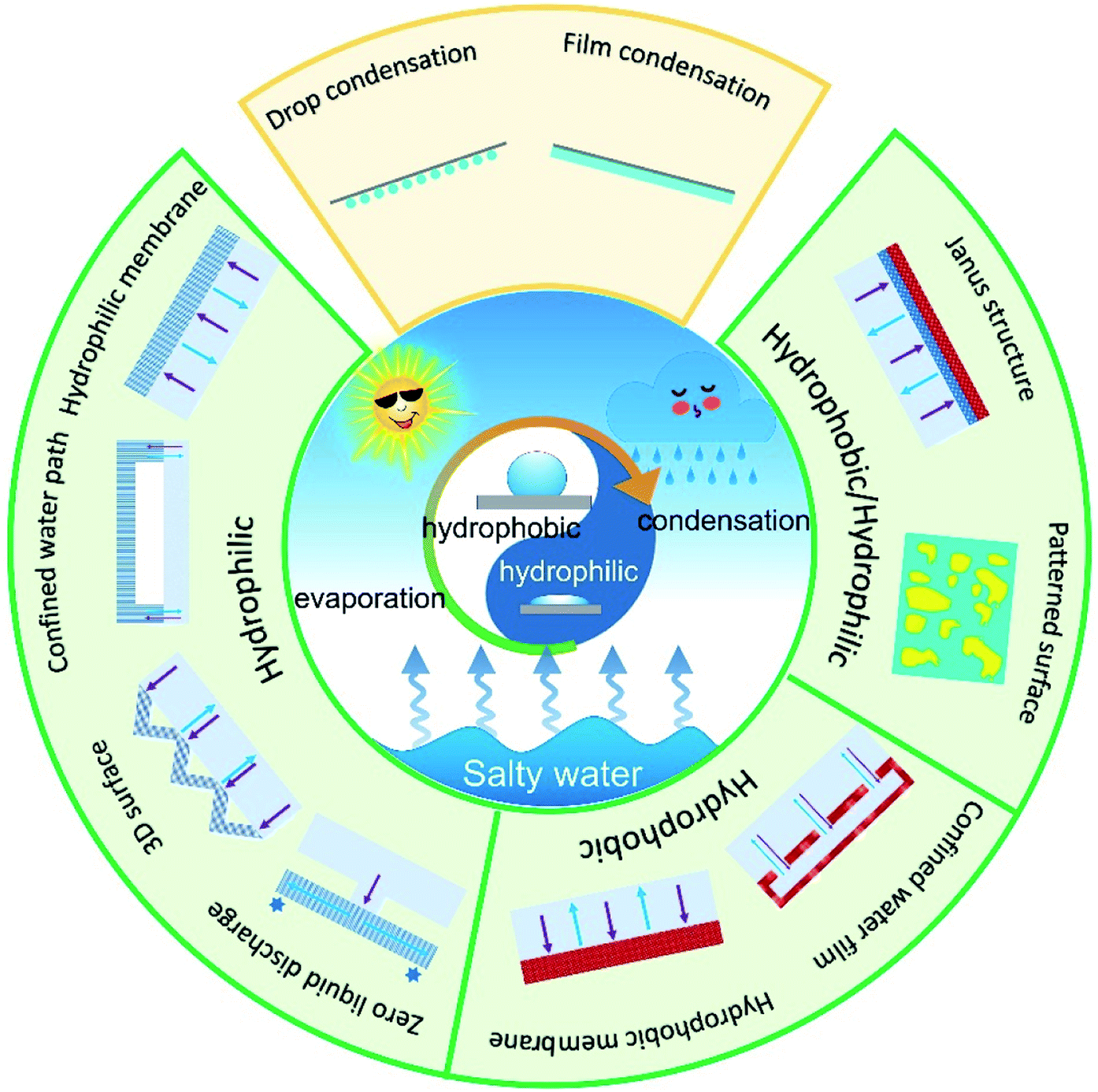 | ||
| Fig. 1 Schematic diagram of solar-driven interfacial desalination system based on super-wettability. According to surface wettability, the evaporators could be categorized into hydrophilic, hydrophobic and hydrophilic/hydrophobic-hybrid types. Following the distinct wettability on the condenser, there are drop-wise and film-wise vapor condensation. | ||
With the rapid development of solar-based desalination, wettability manipulation has emerged as a recent research hot spot. New materials, concepts and fabrication methods have been applied into the evaporators for highly efficient, long-term, and stable water desalination engineering. It is therefore urgent to provide a timely overview on the important progress in this field. In this review, we focus on the latest development in the super-wettability-empowered highly efficient solar desalination systems, including water evaporator and vapor condenser. The water evaporators are categorized into hydrophilic, hydrophobic and hydrophobic/hydrophilic evaporator. The design strategy, work principle and the critical issues in each type of evaporator are discussed. Moreover, we evaluated the influence of surface wettability on vapor condensation. Finally, the challenges and future research prospects for developing high-performance solar evaporation system based on super-wettability are outlooked. This review provides comprehensive guidelines for wettability-enhanced solar desalination systems.
2. Hydrophilic evaporators
2.1. Hydrophilic channels for fast water transport
Most porous absorbers are naturally hydrophilic, which provides water transport channel readily. Hydrophilic interfacial evaporator dates back to 2014. Since then, much effort has been devoted to promoting evaporation efficiency from aspects of extending air/water interface, suppressing heat loss and encouraging salt-rejection and so on. In 2014, Ghasemi et al.20 proposed a double layered structure (DLS) consisting of a carbon foam layer (10 mm thick) supporting an exfoliated graphite layer (∼5 mm thick). In this design, solar vaporization at air/water interface was resulted from the synergy among top, bottom, and middle layer of the desalination system: (i) broad band absorbing in solar spectrum by the top exfoliated graphite layer, (ii) bottom insulating carbon foam, (iii) hydrophilic inner pores in the middle layer promoting water flow directly to the upper surface. A solar-energy conversion efficiency up to 85% at 10 kW m−2 was achieved (Fig. 2a). This porous evaporator was the first attempt to combine light-absorption, thermal insulation and water transport into one system to improve the final evaporation efficiency. Because of the intrinsic porous structure and hydrophilic property, wood was widely utilized to fabricate solar evaporators. In a typical work reported by Li et al., the hydrophilic and micro-channeled porous structures in polypyrrole-decorated wood (PPy-wood) benefited for fast water transport and steam escape.30 This PPy-wood evaporator showed an evaporation rate of 1.014 kg m−2 h−1 and evaporation efficiency of 72.5% (Fig. 2b). Hu et al. prepared hydrophilic cellulose nanofibrils–carbon nanotube (CNF–CNT) aerogel with macro-channels of 200–300 μm in width for water pumping and CNT layer for sunlight absorption. Results showed that a 76.3% solar-energy conversion efficiency and 1.11 kg m−2 h−1 evaporation rate under 1-Sun could be achieved (Fig. 2c).31 Besides, different kinds of photo-thermal materials and porous structure were adapted to fabricate hydrophilic solar evaporator in recent years, such as 3D-printed hierarchical porous cellulose/alginate/carbon black hydrogel solar evaporator,22 MXene hydrogel membrane,32 bacterial nanocellulose (BNC)/polydopamine (PDA) foam,33,34etc. Solar-energy conversion efficiency increased from ∼70.0% to ∼90.0% by material selection and structure regulation. Although solar-to-vapor conversion efficiency was beyond 90% by optimizing the hydrophilic porous structures, the vapor generation fluxes are still below 1.6 kg m−2 h−1 under 1-Sun illumination due to the high vaporization enthalpy of pure water.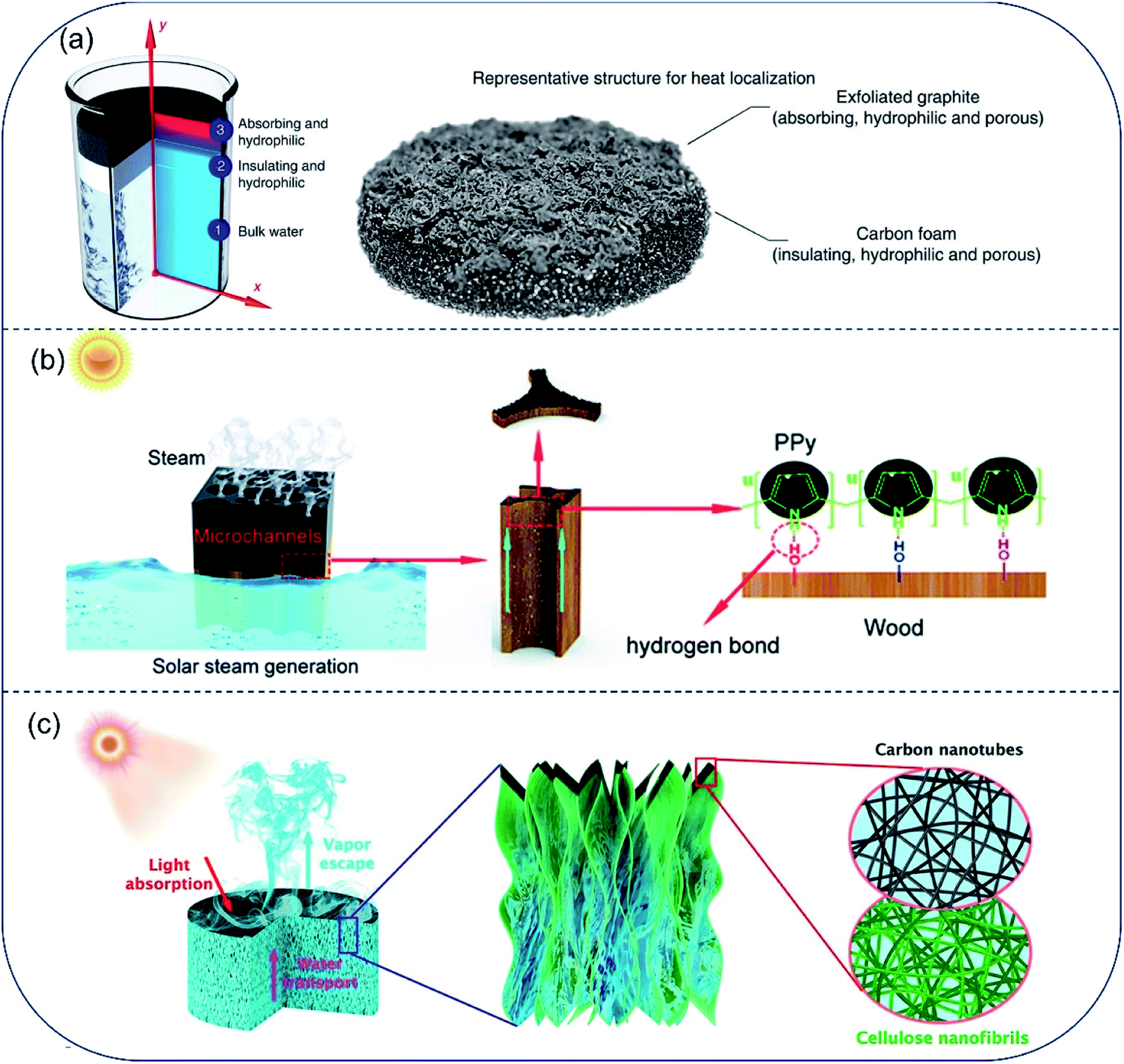 | ||
| Fig. 2 Hydrophilic evaporators with channels for fast water transport. (a) A solar absorber with carbon foam supporting an exfoliated graphite, both layers are hydrophilic to promote capillary rise of water to top surface. Reproduced with permission from ref. 20, copyright (2014) Springer Nature. (b) PPy coated wood with effective photothermal conversion and efficient water supply. Reproduced with permission from ref. 30, copyright (2019) RSC. (c) Schematic illustration of all-nanofiber CNF–CNT aerogel used for solar steam generation. A bilayer structure of bulk CNF aerogel coated with thin layer of CNT constitutes the steam generation device. Reproduced with permission from ref. 31, copyright (2018) ACS. | ||
2.2. Hydrogel evaporators with reduced water vaporization enthalpy
Yu and coworkers made a successful attempt to reduce water vaporization enthalpy and dramatically boosted the water generation rate by tuning water states and phase transition behaviors on hydrogels with various hydrophilic functional groups, including hydroxyl (–OH), amino (–NH2), amide (–CONH–), carboxylic acid (–COOH), and sulfonic acid (–SO3H), and so on.35–38 Firstly, they constructed a hierarchically nanostructured gel (HNG) evaporator using polyvinyl alcohol (PVA) hydrogel and polypyrrole (PPy) nanoparticles. The internal gaps and micro-scale channels inside the hydrophilic PVA hydrogels facilitate rapid water transport to the evaporation surface by molecular diffusion and capillary pumping. More importantly, high ratio of intermediate water exists due to the surface tension-induced weakening of hydrogen bond, which was evidenced by Raman infrared spectra. Specifically, a molecule of free water can interact with four adjacent water molecules through hydrogen bonding in bulk water. While, it interacts with less than four water molecules as in the intermediate state. As a consequence, it takes less energy to break hydrogen bond and escape from liquid surface for an intermediate water molecule than that for a free water.39 The vaporization enthalpy of water confined in the HNG molecular mesh is ∼1700 J g−1, much smaller than that of pure water (2444 J g−1). The HNG showed a high vapor generation rate of 3.2 kg m−2 h−1 under 1-Sun, which is almost twice higher than the one reported previously (Fig. 3a, b).40 Greer et al. designed a PVA/PPy hydrogel membrane populated with three-dimensional (3D) tree-shaped surface microstructures. The reduced water evaporation enthalpy of the PVA/PPy hydrogel and increased light absorption efficiency of the 3D micro-tree arrays enable a high solar vapor generation (3.64 kg m−2 h−1) under 1-Sun (Fig. 3c).41 Thereafter, several other works were reported based on hydrophilic evaporators with reduced vaporization enthalpy and high evaporation rate.42–44 Recently, Cheng et al. reported that the micro-meniscuses and microdroplets appeared on the hydrophilic carbon cloth (CC)/PPy array could reduce water evaporation enthalpy of the system, resulting in a high evaporation rate of 2.16 kg m−2 h−1 under 1-Sun.45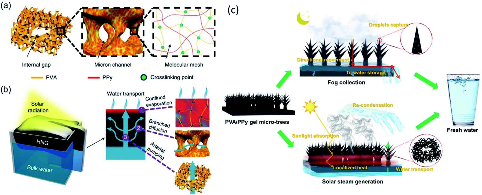 | ||
| Fig. 3 Schematic diagram of highly efficient solar vapor generation basing on tailored water transport in HNGs. (a) The HNG consists of hierarchical porous structures, including internal gaps, micron channels and molecular meshes, wherein the solar absorber (PPy) penetrates the polymeric PVA network of the gel. Reproduced with permission from ref. 40, copyright (2018) Springer Nature. (b) Upon solar radiation, the absorbers in the molecular meshes of the floating generator are heated, facilitating evaporation of water confined in the polymeric network (1). Meanwhile, the evaporated water can be rapidly replenished via branched water diffusion (2) and pumping (3) through micron channels and internal gaps, respectively. Reproduced with permission from ref. 40, copyright (2018) Springer Nature. (c) Conceptual representation of the PVA/PPy hydrogel membrane with micro-topologies that is capable of 24 h freshwater harvesting. Reproduced with permission from ref. 41, copyright (2021) Springer Nature. | ||
2.3. Suppressing heat loss in confined water path
For evaporators designed to make direct contact between absorber surface and the bulk water phase, the bottom hydrophilic layer acts to both insulate heat and provide channels for water transport. However, when the inner pores are filled with water, their heat-insulation performance deteriorates. To improve efficiency of the energy conversion from solar irradiation to water vaporization, an evaporator with confined 2D water path was devised by Zhu and coworkers.46 The evaporator consisted of an upper light-absorber graphene oxide (GO) film and a bottom cellulose-wrapped polystyrene foam. The hydrophilic cellulose wrap provided a 2D water path, and the polystyrene foam (1.6 cm thick, thermal conductivity of ∼0.04 W m−1 K−1) was used as the thermal insulating layer between the GO film and bulk water. Reduced heat loss resulted in an energy transfer efficiency of 78%, which is much higher than that in GO-based direct contact design (39%) (Fig. 4a). By separating water path and heat insulation layer, heat loss to bulk water can be reduced effectively. Guided by the principle of suppressing thermal loss using confined water path, Hu and coauthors fabricated a TiAlON-based hydrophilic NiO disc with 1D water channels. This channel design succeeded in preventing thermal loss to bulk water, and TiAlON-based absorber enhanced solar absorption ability effectively, leading to a solar-energy conversion efficiency of 73.3% (Fig. 4b).47 Moreover, a jellyfish-like solar steam generator was prepared, consisted of a porous carbon black/graphene oxide (CB/GO) composite layer with aligned GO pillars (1D water path) and expanded polystyrene (EPS) matrix. This evaporator showed an energy conversion efficiency of 87.5% (Fig. 4c).48 Similarly, a bilayer evaporator composed of hydrophobic polyvinylidene fluoride (PVDF) nanofibers and hydrophilic carbon black/polyacrylonitrile (CB/PAN) composite nanofiber layers was also prepared through electrospinning technology. The porous hydrophobic PVDF nanofiber layer served both as a floating support and thermal barrier to suppress heat dissipation. The hydrophilic CB/PAN composite nanofiber layer on the top converted solar irradiation into available heat energy. Water that was transported upward through punched holes in the PVDF nanofiber layer spread throughout the hydrophilic CB/PAN composite nanofiber layer quickly under capillary effect. This hydrophobic/hydrophilic double layer assembled evaporator showed a solar energy conversion efficiency of 82.0% under 1-Sun (Fig. 4d).49 Collectively, in the very early stage of solar desalination development, most evaporators demonstrate a solar-to-vapor conversion efficiency between 70% and 80%. After 5 years of progress, the energy conversion efficiency has been pushed to the theoretical limit, with thermal radiation and diffuse reflectance as two major sources for energy loss in the 2D evaporators.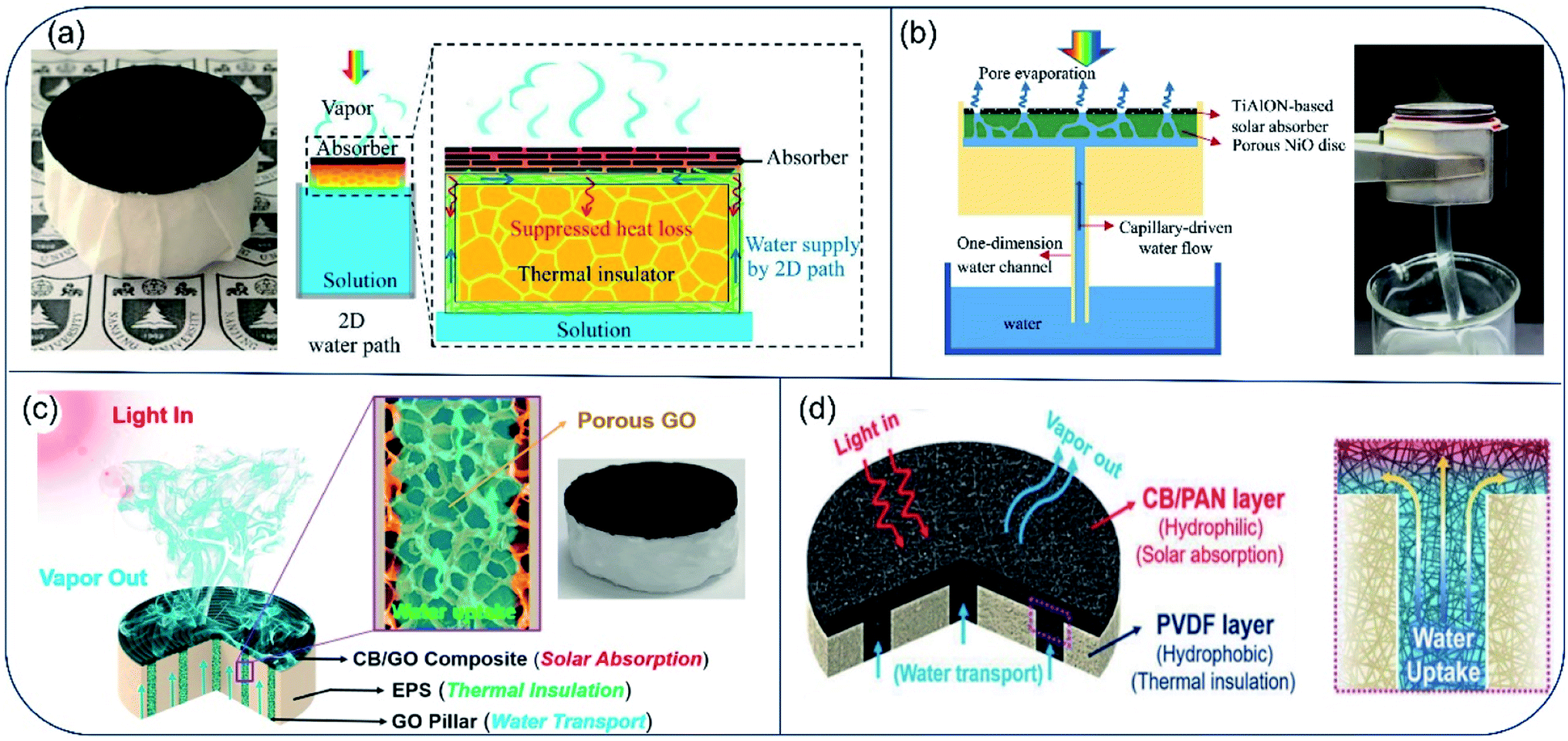 | ||
| Fig. 4 Evaporators with confined water path to suppress heat loss. (a) Schematics of solar desalination devices with suppressed heat loss and 2D water supply path. Reproduced with permission from ref. 46, copyright (2016) PNAS. (b) Conceptual diagram and picture of solar vapor generator with 1D water supply channel. Reproduced with permission from ref. 47, copyright (2017) Elsevier. (c) Principle illustration of the jellyfish-like evaporator. Porous GO pillar functions as water transport channel. EPS matrix acts as thermal insulator layer. The CB/GO composite layer absorbs light and converts it to thermal energy. Reproduced with permission from ref. 48, copyright (2017) Elsevier. (d) Schematic illustration of cross-section of the CB/PAN//PVDF evaporator. Hydrophilic CB/PAN was used to transport water up to the evaporator surface, and hydrophobic PVDF was used as thermal insulator. Reproduced with permission from ref. 49, copyright (2018) Wiley. | ||
2.4. Three-dimensional (3D) structured evaporator surface
To further reduce energy loss induced by thermal radiation and diffuse reflectance, Jiang et al. proposed a bio-inspired 3D photothermal cone with minimum light reflection and heat loss.50 The artificial photothermal cone was facilely fabricated by folding a polypyrrole (PPy) coated PVDF membrane. Owing to the conical morphology, the photothermal cone could absorb 99.2% of light in the solar spectrum, while the plane photothermal film showed only ∼93% light absorbance in the same solar spectrum. Meanwhile, heat loss to the bulk water could be suppressed simply by adjusting the contact area between the cone and water without using thermal insulation layer. For the cone evaporator, 1.70 kg m−2 h−1 of evaporation rate and 93.8% of thermal conversion efficiency under 1-Sun was achieved, which is about 1.7 times as high as the results obtained for the 2D surfaces (Fig. 5a). Soon afterwards, Wang and coworkers reported another 3D cylindrical cup-shaped solar evaporator. Surface of the evaporator was made of hydrophilic quartz glass fibrous (QGF) filter/CuFeMnO4 with a diameter of 4.7 cm and a height of 5–13 cm.51 Wall structure of this design not only absorb reflected light, but also reuse thermal radiation from the bottom of the cup, therefore minimizing the energy loss. Moreover, temperature of the cup's outer wall surface was found to be lower than both that of the inner wall and the surrounding air due to the absence of energy recycle from the bottom part and fast water evaporation on the outer wall. In results, the outer wall gained additional energy from the ambient air and accelerated the local evaporation process. Above all, the cup-shaped structure showed a high energy efficiency close to 100% under 1-Sun and high steam generation rate of 2.04 kg m−2 h−1, which is higher than most 2D evaporation surfaces (Fig. 5b). To adapt diverse environmental conditions, Chen et al. prepared kirigami evaporator using flexible and structurally tailorable cellulose paper, which was functionalized by polypyrrole particles (PPyP). The PPyP was switchable between 2D and 3D structures. Under 1-Sun irradiation, the evaporation rate of the 2D and 3D PPyP were 1.47 kg m−2 h−1 and 2.99 kg m−2 h−1, respectively (Fig. 5c).52 | ||
| Fig. 5 3D structured evaporators. (a) Fabrication scheme of polypyrrole (PPy)-coated photothermal cone. Reproduced with permission from ref. 50, copyright (2018) RSC. (b) Principle of 3D cup-shaped solar evaporator with reduced diffuse reflection energy loss and thermal radiation heat. Reproduced with permission from ref. 51, copyright (2018) Elsevier. (c) Schematic illustration of fabricating 2D/3D switchable PPyP decorated solar evaporator and the water mass change upon outdoor evaporation through the two types of evaporators for 1 day. Reproduced with permission from ref. 52, copyright (2019) ACS. | ||
In 3D evaporators, the 3D structures suppress heat loss, increase evaporate area, improve light-harvesting and absorb excessive energy from surroundings, which all help accelerate the evaporation rate effectively. To date, more and more 3D evaporators with various structures aiming to improve light-harvesting and better thermal management have been established, many of which present high evaporation rate from 2.0 to 3.0 kg m−2 h−1.53–55 On hydrophilic 3D surface, the processes of water transport, water evaporation and salt precipitation coexist. The high evaporation rate on the 3D evaporator calls for fast water transport for a continuous evaporation, which is guaranteed by the high hydrophilicity. Unfortunately, high hydrophilicity and fast water transport also lead to fast salt accumulation and strong adhesion of salt crystals to the 3D surface. Therefore, one should carefully tailor the surface wettability to balance the desalination efficiency and long-term stability of the 3D evaporator.
2.5. Anti-salt accumulation strategy based on salt diffusion in hydrophilic evaporator
Salt accumulation on the vaporization interfaces not only causes dramatical reduction in light absorption, but also blocks water and vapor transport. Although great efforts have been made to improve the evaporation rate and energy utilization efficiency of hydrophilic solar evaporators, salt accumulation on the surface is a still a key challenge for its long-term application. Salt crystal nucleation and growth are prone to take place on the hydrophilic evaporator surface as the concentration of brine increases during solar evaporation.56 Meanwhile, salt ions diffuse back to the bulk liquid from the evaporator surface due to the concentration gradient.57 This dynamic balance between ion concentration and ion diffusion at the evaporator surface determines whether salt accumulation occurs or not. Considering principle of this dynamic balance, a salt-rejective floating solar evaporator was built through rationally tuning ratio of the fabric wick to the total evaporating surface. The hydrophilic fabric wick was able to pump water to the solar-absorbing surface, while pushing the concentrated salt solution down back to bulk water via diffusion and advection. This evaporator exhibited salt-rejection capability even after 7 days evaporation in 3.5 wt% brine under 1-Sun (Fig. 6a).58 Taking advantage of the inherent bimodal porous and interconnected microstructures of balsa wood, He et al. constructed another salt-rejective evaporator capable of transporting high-salinity brine from wood surface back to bulk water.59 Their design succeeded in sustaining stable evaporation even in high-salinity brine (15 wt%) under 6-Suns (Fig. 6b). Afterwards, Dong et al. prepared an evaporator based on carbon nanotubes@SiO2 nanofibrous aerogels (CNFAs), which showed a cellular architecture composed of vertically aligned vessels and porous vessel walls (Fig. 6c1). Due to this unique cellular architecture, the CNFAs exhibited an excellent salt-resist performance for brine with both low and high salinity under the combined effect of convection and diffusion (Fig. 6c2). This evaporator held an evaporation rate of 1.50 kg m−2 h−1 under 1-Sun, and no salt precipitation was evidenced on the surface of aerogel in 20% brine under 6-Suns of irradiation.60 Li et al. prepared attapulgite-based aerogels by freeze-drying method (Fig. 6d1). The vertical channel structure in the aerogel provides pathways allowing for water transmission and circulation (Fig. 6d2, d3), resisting salt accumulation even in highly concentrated brine. The evaporation rate for a 20 wt% brine is 1.3–1.5 kg m−2 h−1.61,62 Based on this salt diffusion strategy, various other evaporators have been developed for solar desalination.63–65 However, as the compensation of salt-resistance, heat loss along with fast convection to bulk water is inevitable, the evaporation efficiency of most hydrophilic evaporators are therefore lower than 90%. | ||
| Fig. 6 Evaporators with fast salt diffusion capable of preventing salt accumulation. (a) Evaporator with wick and insulation structure. The alternated wick design was able to deliver water to surface for evaporation and realize salt rejection through saltwater convection. Reproduced with permission from ref. 58, copyright (2018) RSC. (b) Illustration of the working principle of bimodal evaporator based on porous balsa wood for high salinity brine desalination. Reproduced with permission from ref. 59, copyright (2019) RSC. Schematic diagram showing (c1) the fabrication and architectures of CNFAs as solar evaporator and (c2) salt diffusion, water transportation and light absorption in CNFAs. Reproduced with permission from ref. 60, copyright (2020) Wiley. (d1) Schematic preparation procedures of the attapulgite-based aerogel and (d1, d2) its aligned channel structure. Reproduced with permission from ref. 61, copyright (2021) Elsevier. | ||
2.6. Hydrophilic evaporators with controlled salt precipitation for water and salt recovery from high-salinity brine
High evaporation rate and salt-rejecting are hard to realized simultaneously in the hydrophilic evaporator system, especially for high-salinity brine. Moreover, valuable mineral resources could not be collected in the salt-diffuse-back strategy. Therefore, solar evaporators with controlled salt precipitation were proposed for continuous vapor generation and salt-harvesting. In this mechanism, capillary force drives water to transport ions to a specific region. As water gradually escapes, salt concentrates and precipitates near the water margin. Through rational design of the evaporator's structure, salt precipitation is confined in a specific region on the surface and high light-absorbance could be preserved. The accumulated salt particles may spontaneously drop off or be easily scraped off, realizing salt-recovery and zero-liquid discharge. For instance, Xia et al.66 proposed an umbrella-shaped steam generator with a horizontal evaporation disc and a vertical solution uptake thread. The evaporation disc was a 3-layer structure composed of a light-absorbing layer (CNTs), a water spreading layer (superhydrophilic filter paper) and a thermal insulation layer (PS foam). A twined cotton thread was inserted into the center of the evaporation disc, transporting bulk water from the bottom to the disc atop. The levitated water then spread on the evaporation disc, generating a radial concentration gradient from the centre to the edge. As a result, salt precipitated only at the edge of the evaporation disc, preserving the central surface for efficient light absorption. The accumulated salt fell off the surface under gravity as it grew. Under 1-Sun, the evaporator showed a stable evaporation rate of 1.42 kg m−2 h−1 and solar-conversion-efficiency of 81.2%. Moreover, continuous steam generation and salt harvesting were achieved in long-term operation (over 600 h) owing to the edge-preferred crystallisation and self-falling phenomenon of edge-accumulated salt (Fig. 7a). | ||
| Fig. 7 Hydrophilic evaporators with special structures for water and salt recovery from high-salinity brine. (a) Schematic illustration of the umbrella-like steam generator for continuous solar steam generation and salt harvesting. Reproduced with permission from ref. 66, copyright (2019) RSC. (b1) Design of the biomimetic pyramid-shaped evaporator inspired by a bird beak with capillary rachet capable of transport liquid directionally and peristome of pitcher plant with micro-cavity arrays. (b2) The evaporation performance and salt harvesting versus time. Reproduced with permission from ref. 67, copyright (2020) Springer Nature. (c) Scheme of cup shaped solar evaporator, and its evaporation performance for saturated brine. Reproduced with permission from ref. 68, copyright (2018) ACS. | ||
Different from salt accumulation strategy at the disc edge, Song et al. built a pyramid-shaped evaporator using 3D printing technique. This biomimic design was a combination of asymmetric capillary ratcheted structure from shore-beak and oriented micro-cavity arrays from pitcher plant. Because of the unique structure, water spread fast from bottom to apex of the pyramids along the grooves. There was a thickness and evaporation rate gradient of water film from along the grooves, resulting in the salt concentration gradient and localized salt crystallization at the apex of the pyramid-shaped evaporator. Due to the well-preserved light-absorbing surface and additional energy acquired from the surrounding environment, this design resulted in high evaporation rate of 2.63 kg m−2 h−1 under 1-Sun for high salinity brine (25 wt%) (Fig. 7b1). The locally crystallized salt free standed at the apex without contaminating the rest surface of evaporator, and was easily removed through inclining the evaporator (Fig. 7b2). The high rate of evaporation and easy procedure of salt collection indicate its potential for high-salinity brine recovery during desalination.67
The concept of coupling structures for light-absorbing and salt precipitation was also applied in a cup-shaped evaporator.68 Shi et al. reported an evaporator made of hydrophilic silica–carbon–silica fibrous membrane, expanded polystyrene (EPS) foam and hydrophilic quartz glass fibrous strip. Water was first transported to the bottom center of the cup by the strip passing through a hole in the EPS foam and then spread out to the edges along the radial directions. In this work, only the outer wall was used as water evaporation surface and salt concentration gradually increased on the outer wall due to the continuous water removal via evaporation. Bottom and inner walls of the cup remained clean for light absorption (Fig. 7c). As a result, no salt precipitation was observed at bottom of the inner cup during 24 h-long test for 10 wt% and 15 wt% brine. With rational design, salt ions crystallized at one end of the evaporator strip69 or the termini of the wing-structured evaporator.70 Solar desalination and salt extraction were achieved at the same time. As a promising strategy for high-salinity brine desalination, this site-specific salt crystallization concept has been further validated in other evaporators.71–73
Fast water transportation is the main advantage of the hydrophilic evaporator, which provides efficient water supply and ion diffusion channel. However, the heat loss that comes along with water transportation should be prohibited. Hydrophilic evaporator with rational design of water transport channel have been extensively studied in the past decade. Moreover, directional liquid transport in hydrophilic evaporator provides a special insight into the design of salt recovery evaporator.
3. Hydrophobic evaporators
3.1. Hydrophobic film/particle-based evaporator
Hydrophobic surface is an effective way to prevent salt deposition during seawater desalination. In several works, researchers focused on using hydrophobic surfaces to prevent salt adhesion. Liu et al.74 reported a carbon black-based superhydrophobic gauze, which is able to float on a water tank and selectively heat up the water surface under light irradiation. The evaporation rate was 3 times higher than that for the control (Fig. 8a). Aside from hydrophobic self-floating film, various hydrophobic nanoparticles, such as PFOTS-modified lithiated titania,75 Fe3O4@C core–shell nanostructures76 and magnetic Fe3O4, MnFe2O4, ZnFe2O4, CoFe2O4,77 could also self-assembled into floating thin films with interfacial heating function. The water evaporation efficiency was significantly enhanced by 3 folds as that of the nanoparticle suspension. Similarly, millimeter-sized self-floating hollow carbon spheres (HCSs) with interpenetrating, open-porous carbon shell and huge external voids permitted rapid transport of molecules throughout its hollow structure.78,79 Upon treating salt water (salinity of 3.5%), these HCSs showed a water evaporation rate about two times higher than that of the conventional bulk heating scheme under the same artificial sunlight (Fig. 8b). Due to their nonwetting property, this hydrophobic evaporator generally exhibits improved stability in corrosive and salty environment as well as great recyclability. However, the hydrophobic structure blocks water molecules together with salt ions, which considerably reduces the evaporation rate. Moreover, to avoid salt clogging, the self-floating films require to be ultra-thin, sacrificing thermal insulation. | ||
| Fig. 8 Hydrophobic film/particle-based evaporators. (a) The carbon black-based super-hydrophobic gauze was able to float on the water surface and evaporation occurred at the liquid–air interface. Reproduced with permission from ref. 74, copyright (2015) ACS. (b) Hydrophobic HCSs particles floating on the water surface as evaporator and the evaporation rates using HCSs with different CNTs contents. Reproduced with permission from ref. 79, copyright (2016) Wiley. | ||
3.2. Evaporator with confined thin water film for anti-salt fouling and heat management
To suppress the heat loss and prevent salt accumulation, the concept of confined thin water layer on evaporator surface was proposed. Zhu et al. demonstrated a water lily-inspired hierarchical structure with top hydrophobic absorber for light-absorbance and water vapor escape pathway, and the bottom stand acted for heat insulation.80 A thin water film was sandwiched between the absorber and the stand. The thin water layer was related to stable and efficient solar evaporation from highly concentrated brine in two ways: (i) the absorbed solar energy was concentrated in this thin water layer for evaporation, therefore the heat loss to bulk water could be suppressed effectively, (ii) salt/solute would be excreted downward with water in the channels rather than on the absorber surface. Consequently, this water lily-inspired evaporator enabled 80% solar-to-vapor conversion efficiency upon treating 10 wt% brine and 30 wt% waste-water. Neither fouling nor decrease in evaporation rate was observed until water was completely evaporated (Fig. 9a).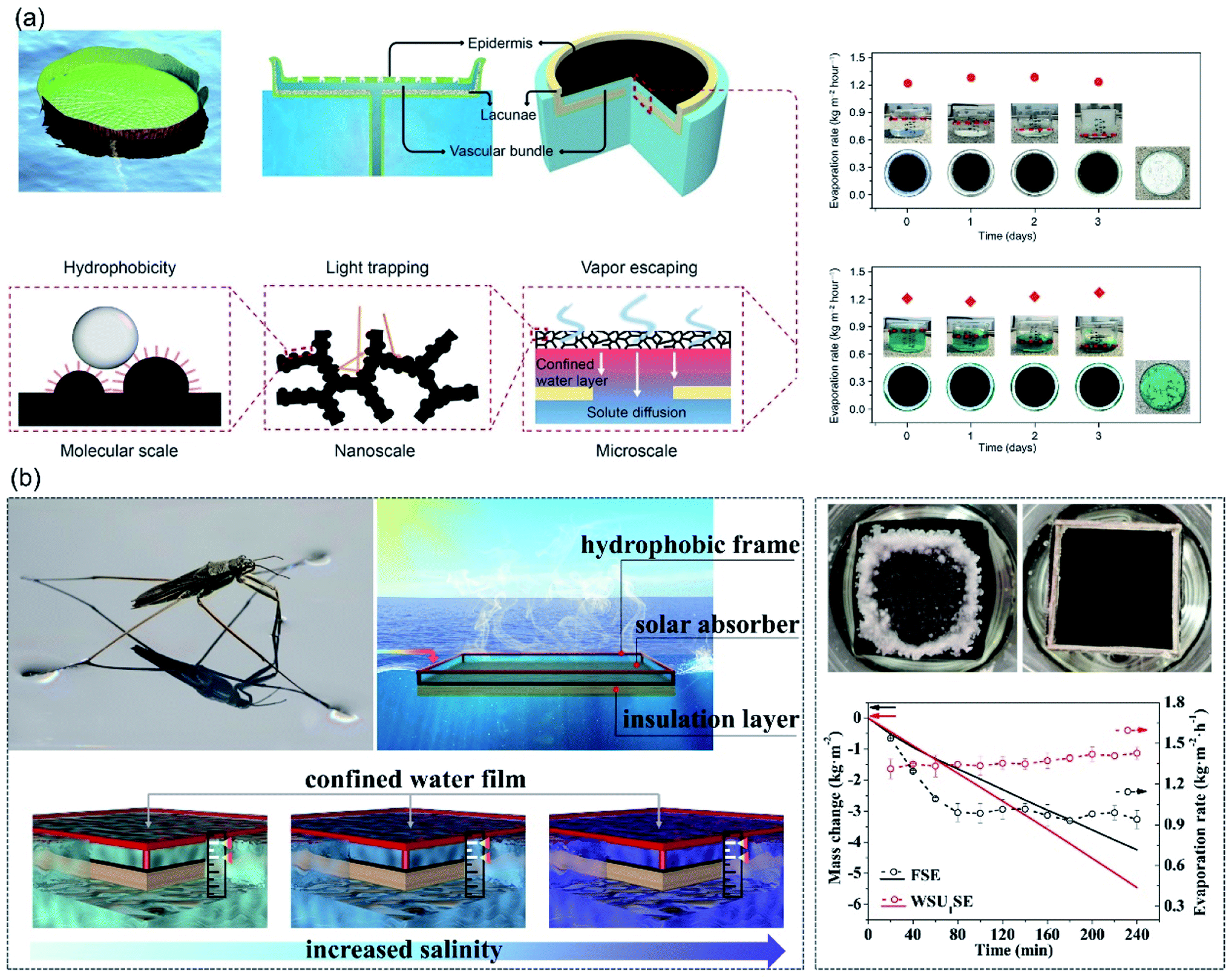 | ||
| Fig. 9 Evaporators with confined thin water film. (a) Design concept of the water lily-inspired hierarchical structure and its performance in treating brine solution and wastewater under solar irradiation. Reproduced with permission from ref. 80, copyright (2019) AAAS. (b) WSUSE with high suspending stability for continuous solar desalination in high-salinity brines (15–20 wt%). Reproduced with permission from ref. 81, copyright (2021) Elsevier. | ||
Based on the strategy of confined thin water film, Wang et al. fabricated a water strider-inspired suspended solar evaporator.81 The water-surface-underneath solar evaporator (WSUSE) with a density of 1.3 g cm−3 consisted of a hydrophobic wood frame, a hydrophilic solar absorber and a heat-insulation layer. Relying on the surface tension force acting on the hydrophobic frame, the solar evaporator suspended stably right underneath water surface, confining a thin water film on the absorber surface, which is beneficial for salt-resistance and efficient energy utilization. And the thin water film was well preserved in long-term desalination. When it was used to treat high-salinity brine (20 wt%), no salt-accumulation was observed during 4 hours evaporation process and evaporation rate of 1.35 kg m−2 h−1 was achieved (Fig. 9b). In this system, it is critically important to maintain the confined thin water film with a constant thickness during long-term desalination for continuous and stable evaporation performance. Due to the weak adhesion of salt crystals to hydrophobic surfaces, salt accumulation issue is avoided, which favors the long-term desalination. In thin-film hydrophobic evaporators, however, salt rejection is achieved at the expense of huge amount heat loss, resulting in low evaporation rate. Whereas the confined thin water film strategy might provide a solution for long-term-stable desalination with higher evaporation rate.
4. Hydrophobic/hydrophilic structured evaporator
4.1. Janus evaporator
Although the hydrophobic evaporator provides an effective way for salt-rejection, its low evaporation rate due to blocked vapor transport and massive heat loss limits its application. Janus membranes are materials with asymmetric structure or property on both sides. In terms of wettability, the hydrophilic/hydrophobic Janus membrane has been widely used in the field of oil-water separation,82,83 fog collection84,85 and intelligent fabrics.86,87 By combining the advantages of the dual layers, the Janus membrane has been applied in the field of seawater desalination as well. With the top hydrophobic surface for light harvesting and the bottom hydrophilic surface for pumping water, solar absorption and water transport were realized on either side of the Janus membrane. Originating from the cooperative effect of water repellency of hydrophobic surface and water affinity of hydrophilic surface, the Janus membrane self-floated on water surface and fixed the air/water interface at the hydrophobic/hydrophilic boundary.88 The hydrophobic surface stayed above the water surface while the hydrophilic layer was immersed in water. Therefore, salt could only be deposited in the hydrophilic layer and quickly dissolved back to water because of continuous water pumping, resulting in long-term stability. In Janus evaporators, the combining effect from high light-harvesting capability, fast vaporization and sufficient water supply are critically important to realize highly efficient desalination. Note that, modification on surface wettability is an essential step to fabricate the Janus structure. Moreover, the hydrophobic coating materials should be transparent enough to preserve high light-harvesting capability. Since vapor generates at the air/water interface and escapes from the pore channel of the hydrophobic side, thickness and microstructure of the hydrophobic layer are essential for vaporization. Water supply and salt diffusion coexist in the hydrophilic layer. Tortuosity and length of the channel in the hydrophilic layer is important to sustain water replenishment and fast salt diffusion. Therefore, the detail structure of a Janus evaporator must be carefully tailored for high rate evaporation. In 2018, a flexible Janus membrane was proposed by Xu et al., where a hydrophobic polymethyl methacrylate (PMMA)/carbon black (CB) layer was attached to hydrophilic polyacrylonitrile (PAN) films by electrospinning.89 The upper hydrophobic layer was used for light absorption and water evaporation, and bottom hydrophilic layer for pumping water. No salt accumulation was observed either inside or on the top of evaporator surface after cycling for 16 days. This Janus evaporator exhibited stable energy conversion efficiency (72%) and evaporation rate (1.3 kg m−2 h−1) over 16 days under 1-Sun, while the evaporation performance of the CB/PAN membrane declined over time because of salt accumulation (Fig. 10a). | ||
| Fig. 10 Janus evaporators. (a) Structures of the flexible CB/PMMA-PAN Janus membrane for solar evaporation. Reproduced with permission from ref. 89, copyright (2018) Wiley. (b) Fabrication and working principle of solar evaporator based on PMPF/PF Janus structure. Reproduced with permission from ref. 92, copyright (2022) Elsevier. (c) Schematics illustrating the interfacial solar steam processes of SiO2/CNF/CNT Janus evaporator. Reproduced with permission from ref. 93, copyright (2019) RSC. (d) HHNDL solar-driven Janus generator. Reproduced with permission from ref. 100, copyright (2018) RSC. (e) Janus HN/NiO evaporator. Reproduced with permission from ref. 101, copyright (2020) RSC. (f) Janus evaporator with 2D water channel. Reproduced with permission from ref. 102, copyright (2021) Elsevier. | ||
Generally, the Janus membrane can be prepared in two ways: asymmetric fabrication and asymmetric decoration.90,91 Asymmetric fabrication is a simple method to obtain a Janus membrane by combining the hydrophobic and hydrophilic layer together. For instance, Janus evaporator was developed by stacking the superhydrophobic PMPF (PDMS/MXene/polydopamine modified fabric) on the superhydrophilic PF (polydopamine modified fabric). The superhydrophobic fabric acted as solar absorber and resisted salt-accumulation. 1.52 kg m−2 h−1 of evaporation rate for 20 wt% brine was achieved in this design (Fig. 10b).92 However, the weak interfacial interaction between the two layers may compromise the stability of the as-prepared membranes. Therefore, asymmetric decoration is widely employed to fabricate Janus evaporator with improved stability. For example, a Janus evaporator based on a SiO2/cellulose nanofiber (CNF)/carbon nanotube (CNT) hybrid network with a pore structure of low tortuosity was reported, where hexamethyldisilazane (HDMS)-treated SiO2 functioned as the hydrophobic coating, the CNFs as the building-blocks for the robust hydrophilic backbone and the CNTs as photothermal material for efficient solar-thermal conversion. The asymmetric wettability enabled the evaporator to float on water with the hydrophobic layer out of the water for better heat focus and the hydrophilic layer in the water for continuous water pumping, while the pore structure with low tortuosity endowed the evaporator with excellent salt excretion capability. This Janus evaporator exhibited stable steam generation with over 80% efficiency in continuous tests (100 hours) for 3.5 wt% brine under 1 Sun (Fig. 10c).93 In addition, other Janus evaporators based on asymmetric decoration were also reported, such as wood-based Janus evaporator,94 3D Janus PDMS/PDA/polyurethane (PU) evaporator,95 photothermal materials/PDMS modified melamine foam,96–98 polypyrrole-based Janus aerogel,99etc. In all, the Janus evaporator is a porous monolith with several centimeters in thickness. Therefore, low tortuosity in hydrophilic part becomes necessary for fast water transport.
However, we should note that heat loss to bulk water along with salt diffusion is inevitable for the general hydrophobic/hydrophilic Janus structure. Therefore, porous foam is sometimes positioned under the Janus membrane to suppress heat loss to bulk water. For instance, Que and co-workers100 prepared the hydrophobic/hydrophilic nanopore double-layer (HHNDL) structure on a commercial filter. The inner pores of the filter were decorated by Cu2SnSe3 (CTSe) and Cu2ZnSnSe4 (CZTSe) which was coated by oleylamine. The stacked hydrophobic CTSe and CZTSe nanosphere layer converted solar light to heat, resisted salt deposition and provided vapor evaporation pathways, while the lower hydrophilic filter membrane guaranteed water storage and supplied for efficient vapor generation, together achieving long-term stability of the device under continuous working conditions. Meanwhile, a piece of floatable polyurethane foam with a bundle of infiltrative nonwoven fabrics was settled at the bottom of the Janus membrane. Water was uptaken to the hydrophilic filter by the nonwoven fabrics by capillary force. The hydrophilic filter membrane was physically separated by the foam instead of being in direct contact with bulk water to minimize heat loss. As such, the conductive heat loss to the underlying bulk water was ∼2.3%. 86.6% solar thermal conversion efficiency and an average of 1.657 kg m−2 h−1 evaporation rate under 1-Sun were achieved in this design, and salt-accumulation was not observed on the evaporator surface after 10 hours of desalination (Fig. 10d). Similarly, Xiong et al.101 reported a paper decorated by sodium-oleate modified hydrophobic ultrafine hydroxyapatite nanowires (HN), and black NiO nanoparticles were deposited on HN paper as the photothermal material. A piece of styrofoam wrapped by air-laid paper was floated on water surface in a beaker, and the HN paper was placed on top of the air-laid paper. With the efficient light absorption and energy conversion, fast water transport, fast salt-rejection, and excellent heat insulation, light-to-heat conversion efficiency of the evaporator could reach 83.5% under 1-Sun. Furthermore, a test of stable desalination within 8 hours was also accomplished (Fig. 10e). Recently, a Janus solar evaporator has been built by covering a bilayer film consisting hydrophobic soot-coated cloth and hydrophilic cloth on a cellulose aerogel wrapped by polyethylene (PE). Such a structural design not only minimized the heat conduction loss comparing to the conventional flat Janus structure in the direct contact mode, but also resisted salt accretion better than common hydrophilic solar evaporator with 2D water channels. 90.0% photothermal conversion efficiency was achieved under 1-Sun and the evaporation surface was well preserved after 10 h desalination for 3.5 wt% brine (Fig. 10f).102 It is noticed that the foam/aerogel between the Janus membrane and water surface could inhibit heat loss from solar absorber to bulk water effectively. Nevertheless, salt-diffusion was confined in a thin hydrophilic membrane, which is sandwiched between the hydrophobic membrane and thick insulation foam. Such structure may generate adverse effect on the salt-rejection ability. Although Janus structures demonstrate superior capacity for solving the salt-fouling issue, there is a trade-off between efficient salt-resistance and low heat loss in this system. Moreover, the high-concentration brine at the hydrophobic/hydrophilic interface is prone to diffuse back to the bulk liquid, forfeiting the chance of harvesting useful minerals during this process. Similar to hydrophobic evaporators, the Janus structure exhibited promising salt rejection performance. Additionally, efficient water supply is guaranteed by the bottom hydrophilic layer. Thus, higher evaporation rate is obtained for the Janus evaporators.
4.2. Evaporator with hydrophobic/hydrophilic patterned surface
In previous scenarios, water molecules escape from surfaces with homogeneous wettability (hydrophobic or hydrophilic) regardless of evaporator structure. It has been reported that on the hydrophobic/hydrophilic composite surface, the evaporation rate is high at the hydrophilic region when the water layer is thin; meanwhile, a considerable number of water molecules also evaporate from the hydrophobic region. As a result, the evaporation of nanoscale water on hydrophobic/hydrophilic patterned surface is faster than that on surfaces with a single wettability.103 Based on this principle, Yu et al. fabricated a hydrophilic hydrogel evaporator with hydrophobic island-shaped patches (Fig. 11).104 On the patchy-surface of hydrogel (PSH), the hydrophilic region accommodated a water film with increased thickness to reduce the interaction between the outmost water molecules and the hydrogel surface, which enhanced the evaporation flux. And a significant amount of water molecules diffusing from the hydrophobic region near the elongated water contact lines also contributed to ultra-efficient evaporation. By controlling coverage of hydrophobic islands on the surface, the evaporator made of hydrogel with patterned wettability could achieve a high solar vapor generation rate of ∼4.0 kg m−2 h−1 with 93% overall efficiency under 1-Sun irradiation, higher than hydrogel-based evaporators with a hydrophilic (∼3.6 kg m−2 h−1) or a hydrophobic surface (∼3.0 kg m−2 h−1).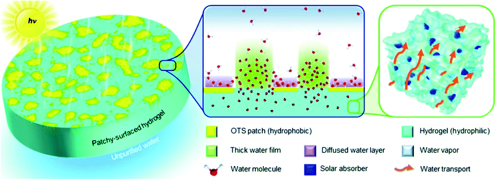 | ||
| Fig. 11 Illustration of patchy-surface hydrogels (PSHs) for enhanced solar-driven evaporation. Reproduced with permission from ref. 104, copyright (2020) RSC. | ||
In solar desalination, appropriate evaporator should be chosen carefully by considering the conditions in practice, such as ion concentration, solar energy intensity, service lifetime and whether salt recovery is preferred. Compared with hydrophilic evaporator, the hydrophobic/Janus evaporator with non-wetting property shows stable evaporation performance in different concentrated brines and under varied illumination intensity, which is a big step forward in practical desalination. On the hydrophobic/Janus evaporators, salt ions diffused back to brine during continuous evaporation, while they precipitated at designated regions on hydrophilic evaporators. Consequently, the hydrophilic evaporator is more suitable for resource recovery from wastewater and zero-liquid discharge desalination.
5. The influence of surface wettability on vapor condensation
All the above works improve the freshwater productivity of solar stills by increasing the evaporation efficiency. Besides, condensation is another crucial part of energy conversion process and thus plays a major role in the working efficiency of solar stills. Among the many factors affecting the vapor condensation performance, wettability is perhaps the first one to consider.Cao et al.105 reported a hydrophobic/hydrophilic hybrid coating to improve water harvesting via enhanced vapor condensation in solar water desalination. Through coordinating the droplet growth and removal behaviors, a dropwise collection process on the hybrid surface (F–SiO2/TiO2 weight ratio of 1![[thin space (1/6-em)]](https://www.rsc.org/images/entities/char_2009.gif) :1) was realized, generating a water collection rate of 1047 mg cm−2 h−1, much more than that on the superhydrophilic TiO2 surface (572 mg cm−2 h−1) and the superhydrophobic F–SiO2 surface (497 mg cm−2 h−1). The hybrid coating also showed good day-time radiative cooling performance (Fig. 12a). Unfortunately, transparency of the hybrid coating was quite low. Vapor condensation experiment based on such coating was therefore only carried out in a simulated vapor set-up rather than real solar evaporating environment. To address the problem, Zanganeh et al.106 prepared condensation surfaces with reduced wettability by dip coating silicon nanoparticles. As a result, drop-wise condensation on the nanoparticle-coated surface produced more condensates than film-wise condensation on the bare surface for cases in any inclining angle. Meanwhile, low wettability enhanced water dripping, especially for slightly tilted surfaces (Fig. 12b). In two later works, the author claimed that the higher heat transfer rate, higher surface renewal rate and faster drop movement were responsible for the higher efficiency during dropwise condensation.107,108 Besides, Thakur et al.109 demonstrated higher water yield through drop-wise condensation. In their experiments, transparent nano-silicon-coated hydrophobic glass cover could increase water production by 15.6% than bare hydrophilic glass. Moreover, Khanmohammadi and Khanjani used cold plasma to change the wettability of the condensation surface from film condensation to drop condensation.110 Final freshwater productivity of the solar still increased by 25.7% (Fig. 12c) comparing with surface before plasma treatment.
:1) was realized, generating a water collection rate of 1047 mg cm−2 h−1, much more than that on the superhydrophilic TiO2 surface (572 mg cm−2 h−1) and the superhydrophobic F–SiO2 surface (497 mg cm−2 h−1). The hybrid coating also showed good day-time radiative cooling performance (Fig. 12a). Unfortunately, transparency of the hybrid coating was quite low. Vapor condensation experiment based on such coating was therefore only carried out in a simulated vapor set-up rather than real solar evaporating environment. To address the problem, Zanganeh et al.106 prepared condensation surfaces with reduced wettability by dip coating silicon nanoparticles. As a result, drop-wise condensation on the nanoparticle-coated surface produced more condensates than film-wise condensation on the bare surface for cases in any inclining angle. Meanwhile, low wettability enhanced water dripping, especially for slightly tilted surfaces (Fig. 12b). In two later works, the author claimed that the higher heat transfer rate, higher surface renewal rate and faster drop movement were responsible for the higher efficiency during dropwise condensation.107,108 Besides, Thakur et al.109 demonstrated higher water yield through drop-wise condensation. In their experiments, transparent nano-silicon-coated hydrophobic glass cover could increase water production by 15.6% than bare hydrophilic glass. Moreover, Khanmohammadi and Khanjani used cold plasma to change the wettability of the condensation surface from film condensation to drop condensation.110 Final freshwater productivity of the solar still increased by 25.7% (Fig. 12c) comparing with surface before plasma treatment.
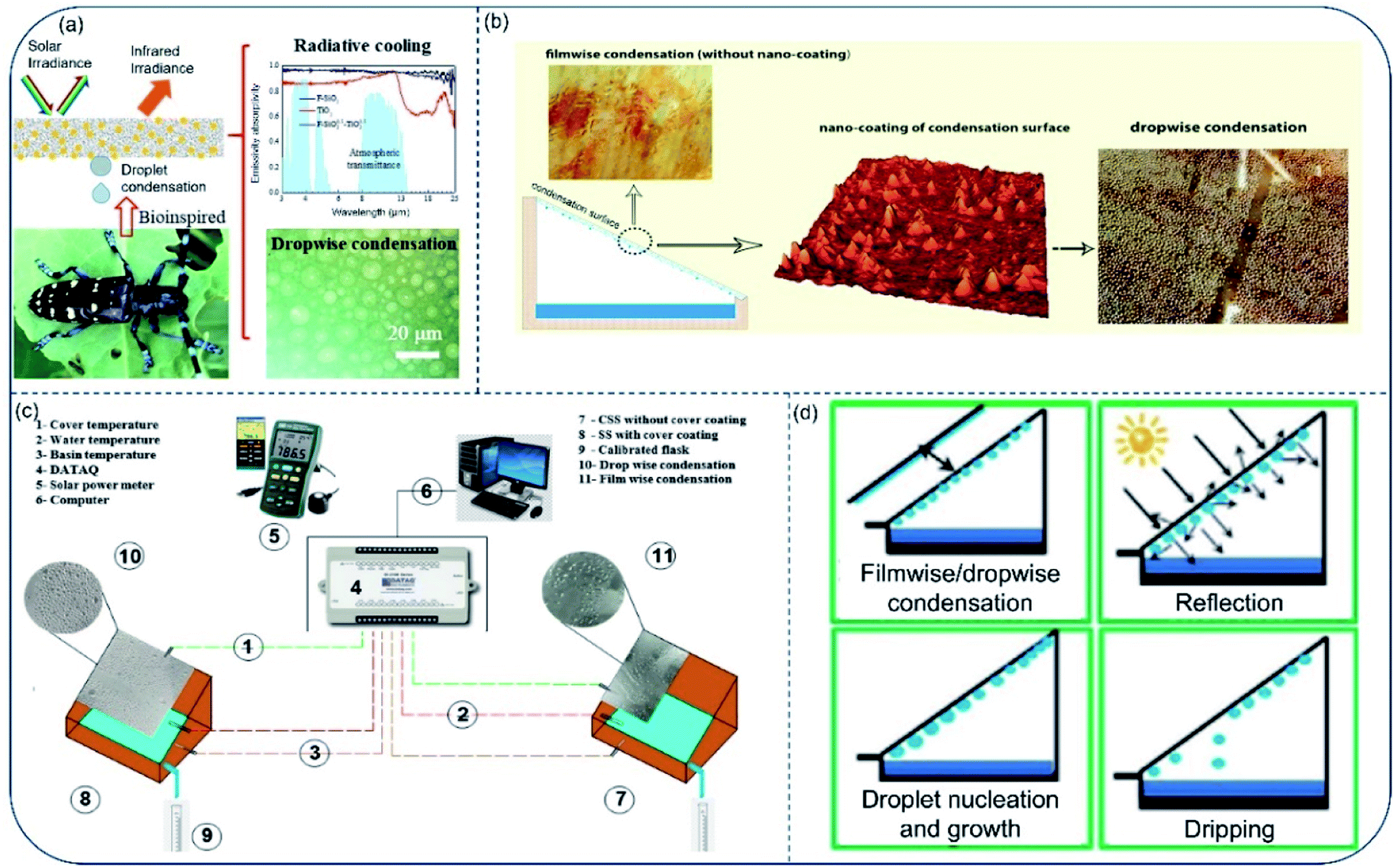 | ||
| Fig. 12 Vapor condensation on surfaces with different wettability. (a) Bioinspired hydrophilic–superhydrophobic hybrid surfaces for dropwise condensation and radiative cooling. Reproduced with permission from ref. 105, copyright (2021) Elsevier. (b) Different vapor condensation models on surface with and without silicon nanoparticles coating. Reproduced with permission from ref. 106, copyright (2019) Elsevier. (c) Schematic illustration of the components within solar stills with dropwise and film wise condensation. Reproduced with permission from ref. 110, copyright (2021) Elsevier. (d) Possible phenomena associated with condensation surface in a solar still. Reproduced with permission from ref. 111, copyright (2013) Elsevier. | ||
In 2013, Bhardwaj et al. experimentally investigated impact of condensation surface's wettability on the productivity of solar stills.111 According to their results, contact angle was the most important factor to consider when choosing material for condensation surface. They found that in wetted condition, materials with low contact angles (film-wise condensation) allow more solar irradiation to pass through than materials with higher contact angles (drop-wise condensation), resulting in faster water production (Fig. 12d). Generally, droplet growth and removal are the two main components in freshwater collection. In recent studies, people show that drop-wise condensation on surfaces with low free energy improves the efficiency of condensed water removal/collection. However, the impact of surface wettability on droplet growth has rarely been considered. In fact, water droplets formed on the hydrophobic surface increase the reflection of solar irradiation, which considerably reduces water production efficiency in practical application. In short, the impact of surface wettability on water collection is still under intense research up to now, therefore, comprehensive study should be carried out to optimize vapor condensation taking accounts the influence of wettability.
6. Outlooks and challenges
In this review, we summarize the solar-based interfacial desalination system with special wettability. Different types of wettability were introduced into the evaporation and condensation part to facilitate both phase transitions of water molecules and motion of salt ions for developing high-performance, sustainable solar-based interfacial desalination system. Considerable progresses have been achieved in improving the distillation efficiency. Yet there remain some significant barriers before the systems could be implemented commercially in large scales. A series of major challenges and prospects are summarized as below:(1) Though some solar-based evaporators demonstrate relatively high evaporation rate, most of the evaporator surface are limited to small size, i.e., several centimeters. Large-sized evaporator is essential for practical application, which may exhibit totally different performance with small-sized evaporator, for instance, limited water supply, easy salt-fouling and unstable floating status, etc. Some of the current strategies are not suitable for large-sized evaporators, the performance of which should be considered in further study.
(2) In laboratory experiments, the probing liquid is mostly pure NaCl brine, which is much different from the real concentrated seawater brines. Other contaminant (such as fatty acid fat, oil, metal ions, bacterial, etc.) will alter salt crystallization and scaling behavior, resulting in more complicated and severe blockage than pure NaCl accumulation does.71,112–114 The impact of combined pollutants was studied in some works, but a systematical exploration is still in absence. Therefore, the stability of evaporator dealing with real seawater is an issue worth discussing in near future.
(3) When the sunlight is perpendicular to an absorbing surface, the irradiation light has the highest power density on the surface. Since the incidence angle of sunlight is varied in the whole day, sun-tracking system has been widely used in photovoltaics system.115–117 However, sun-tracking on water surface is more difficult than that on land due to the fluidity of liquid.118,119 The driving of sun-trackers in large-sized evaporators is hard to realize. And the varied light intensity during daytime should be considered in practical application. It is speculated that liquid crystal elastomer or negative thermal expansion material are feasible to fabricate sun-tracking evaporator in water environment.
(4) The production rate of fresh water in a sealed solar evaporator is usually lower than the evaporation rate in an open air, which is a big challenge for freshwater production. Problem is that the low condensation rate results in high humid environment and light reflection and scattering, which further compromise the evaporation rate. Recently, some elegant designs have been developed to improve vapor condensation efficiency, but the current condensation rate is still no match for the rapid increased evaporation rate. Droplet growth and removal are essential to freshwater collection, which has been studied substantially in the field of fog harvesting. Relevant studies offer many useful guidelines for the surface design of vapor condensers. In this aspect, radiative cooling and directional liquid transport might be the two most effective strategies to improve the overall condensation efficiency. Moreover, light transmittance of the vapor condenser in long-term desalination should also be considered carefully.
Conflicts of interest
There are no conflicts to declare.References
- M. M. Mekonnen and A. Y. Hoekstra, Sci. Adv., 2016, 2, e150032 CrossRef PubMed.
- M. Kummu, J. H. A. Guillaume, H. de Moel, S. Eisner, M. Flörke, M. Porkka, S. Siebert, T. I. E. Veldkamp and P. J. Ward, Sci. Rep., 2016, 6, 38495 CrossRef CAS PubMed.
- E. Jones, M. Qadir, M. T. van Vliet, V. Smakhtin and S. M. Kang, Sci. Total Environ., 2019, 657, 1343–1356 CrossRef CAS PubMed.
- M. Elimelech and W. A. Phillip, Science, 2011, 333, 712–717 CrossRef CAS PubMed.
- L. Henthorne and B. Boysen, Desalination, 2015, 356, 129–139 CrossRef CAS.
- B. E. Logan and M. Elimelech, Nature, 2012, 488, 313–319 CrossRef CAS PubMed.
- J. Jairo Feria-Diaz, M. Cristina Lopez-Mendez, J. Pablo Rodriguez-Miranda, L. Carlos Sandoval-Herazo and F. Correa-Mahecha, Processes, 2021, 9, 262 CrossRef.
- Z. Deng, J. Zhou, L. Miao, C. Liu, Y. Peng, L. Sun and S. Tanemura, J. Mater. Chem. A, 2017, 5, 7691–7709 RSC.
- D. Van-Duong and H.-S. Choi, Global Challenges, 2018, 2, 1700094 CrossRef PubMed.
- M. Shinde, R. Navthar and S. M. Shinde, Int. J. Ambient Energy, 2022, 43, 1420–1428 CrossRef.
- P. Tao, G. Ni, C. Song, W. Shang, J. Wu, J. Zhu, G. Chen and T. Deng, Nat. Energy, 2018, 3, 1031–1041 CrossRef.
- C. Chen, Y. Kuang and L. Hu, Joule, 2019, 3, 683–718 CrossRef CAS.
- G. Liu, T. Chen, J. Xu, G. Yao, J. Xie, Y. Cheng, Z. Miao and K. Wang, Cell Rep. Phys. Sci., 2021, 2, 100310 CrossRef CAS.
- F. He, X. Wu, J. Gao and Z. Wang, J. Mater. Chem. A, 2021, 9, 27121–27139 RSC.
- Z. Li, X. Xu, X. Sheng, P. Lin, J. Tang, L. Pan, Y. V. Kaneti, T. Yang and Y. Yamauchi, ACS Nano, 2021, 15, 12535–12566 CrossRef CAS PubMed.
- K. Y. Xu, C. B. Wang, Z. T. Li, S. M. Wu and J. L. Wang, Adv. Funct. Mater., 2020, 31, 2007855 CrossRef.
- W. Guan, Y. Guo and G. Yu, Small, 2021, 17, 2007176 CrossRef CAS PubMed.
- X. Dong, S. Gao, S. Li, T. Zhu, J. Huang, Z. Chen and Y. Lai, Mater. Chem. Front., 2021, 5, 1510–1524 RSC.
- Z. Yu, T. Zhu, J. Zhang, M. Ge, S. Fu and Y. Lai, Adv. Funct. Mater., 2022, 32, 2200359 CrossRef CAS.
- H. Ghasemi, G. Ni, A. M. Marconnet, J. Loomis, S. Yerci, N. Miljkovic and G. Chen, Nat. Commun., 2014, 5, 4449 CrossRef CAS PubMed.
- L. Zhou, Y. Tan, J. Wang, W. Xu, Y. Yuan, W. Cai, S. Zhu and J. Zhu, Nat. Photonics, 2016, 10, 393–398 CrossRef CAS.
- J. Yuan, X. Lei, C. Yi, H. Jiang, F. Liu and G. J. Cheng, Chem. Eng. J., 2022, 430, 132765 CrossRef CAS.
- L. Hao, N. Liu, H. Bai, P. He, R. Niu and J. Gong, J. Colloid Interface Sci., 2022, 608, 840–852 CrossRef CAS PubMed.
- F. Liu, L. Xia, L. Zhang, F. Guo, X. Zhang, Y. Yu and R. Yang, ACS Appl. Mater. Interfaces, 2021, 13, 55299–55306 CrossRef CAS PubMed.
- H. Yu, L. Yan, Y. Shen, S. Chen, H. Li, J. Yang and Z. Xu, Research, 2020, 2020, 3241758 CrossRef CAS PubMed.
- L. Li, Q. Li, Y. Feng, K. Chen and J. Zhang, ACS Appl. Mater. Interfaces, 2022, 14, 2360–2368 CrossRef CAS PubMed.
- D. Han, Z. Chen, J. Li, J. Mao, Z. Jiao, W. Wang, W. Zhang, Y. Zhang and H. Sun, ACS Appl. Mater. Interfaces, 2020, 12, 25435–25443 CrossRef CAS PubMed.
- H. Zhao, J. Zhou, Z. Yu, L. Chen, H. Zhan, H. Zhu, J. Huang, L. Shi and S. Yu, Cell Rep. Phys. Sci., 2020, 1, 100074 CrossRef.
- H. Fu, M. Dai, H. Song, X. Hou, F. Riaz, S. Li, K. Yang, I. Ali, C. Peng and M. Sultan, Energies, 2021, 14, 7050 CrossRef CAS.
- Z. Wang, Y. Yan, X. Shen, C. Jin, Q. Sun and H. Li, J. Mater. Chem. A, 2019, 7, 20706–20712 RSC.
- F. Jiang, H. Liu, Y. Li, Y. Kuang, X. Xu, C. Chen, H. Huang, C. Jia, X. Zhao, E. Hitz, Y. Zhou, R. Yang, L. Cui and L. Hu, ACS Appl. Mater. Interfaces, 2018, 10, 1104–1112 CrossRef CAS PubMed.
- B. Zhang, P. W. Wong and A. K. An, Chem. Eng. J., 2022, 430, 133054 CrossRef CAS.
- Q. Jiang, H. Gholami Derami, D. Ghim, S. Cao, Y.-S. Jun and S. Singamaneni, J. Mater. Chem. A, 2017, 5, 18397–18402 RSC.
- Q. S. Jiang, L. M. Tian, K. K. Liu, S. Tadepalli, R. Raliya, P. Biswas, R. R. Naik and S. Singamaneni, Adv. Mater., 2016, 28, 9400–9407 CrossRef CAS PubMed.
- T. Wang and S. Gunasekaran, J. Appl. Polym. Sci., 2006, 101, 3227–3232 CrossRef CAS.
- T. Terada, Y. Maeda and H. Kitano, J. Phys. Chem., 1993, 97, 3619–3622 CrossRef CAS.
- Z. H. Ping, Q. T. Nguyen, S. M. Chen, J. Q. Zhou and Y. D. Ding, Polymer, 2001, 42, 8461–8467 CrossRef CAS.
- F. Yang, J. Chen, Z. Ye, D. Ding, N. V. Myung and Y. Yin, Adv. Funct. Mater., 2020, 31, 2006294 CrossRef.
- F. Zhao, Y. H. Guo, X. Y. Zhou, W. Shi and G. H. Yu, Nat. Rev. Mater., 2020, 5, 388–401 CrossRef.
- F. Zhao, X. Y. Zhou, Y. Shi, X. Qian, M. Alexander, X. P. Zhao, S. Mendez, R. G. Yang, L. T. Qu and G. H. Yu, Nat. Nanotechnol., 2018, 13, 489–495 CrossRef CAS PubMed.
- Y. Shi, O. Ilic, H. A. Atwater and J. R. Greer, Nat. Commun., 2021, 12, 2797 CrossRef CAS PubMed.
- X. Zhou, F. Zhao, Y. Guo, B. Rosenberger and G. Yu, Sci. Adv., 2019, 5, eaaw5484 CrossRef CAS PubMed.
- Y. H. Guo, H. Y. Lu, F. Zhao, X. Y. Zhou, W. Shi and G. H. Yu, Adv. Mater., 2020, 32, 1907061 CrossRef CAS PubMed.
- Q. Guan, Z. Han, Z. Ling, H. Yang and S. Yu, Nano Lett., 2020, 20, 5699–5704 CrossRef CAS PubMed.
- Z. Yu, R. N. Gu, Y. Tian, P. F. Xie, B. C. Jin and S. A. Cheng, Adv. Funct. Mater., 2022, 32, 2108586 CrossRef CAS.
- X. Li, W. Xu, M. Tang, L. Zhou, B. Zhu, S. Zhu and J. Zhu, Proc. Natl. Acad. Sci. U. S. A., 2016, 113, 13953–13958 CrossRef CAS PubMed.
- H. Liu, X. Zhang, Z. Hong, Z. Pu, Q. Yao, J. Shi, G. Yang, B. Mi, B. Yang, X. Liu, H. Jiang and X. Hu, Nano Energy, 2017, 42, 115–121 CrossRef CAS.
- Y. Li, T. Gao, Z. Yang, C. Chen, Y. Kuang, J. Song, C. Jia, E. M. Hitz, B. Yang and L. Hu, Nano Energy, 2017, 41, 201–209 CrossRef CAS.
- T. Gao, Y. Li, C. Chen, Z. Yang, Y. Kuang, C. Jia, J. Song, E. M. Hitz, B. Liu, H. Huang, J. Yu, B. Yang and L. Hu, Small Methods, 2019, 3, 1800176 CrossRef.
- Y. Wang, C. Wang, X. Song, M. Huang, S. K. Megarajan, S. F. Shaukat and H. Jiang, J. Mater. Chem. A, 2018, 6, 9874–9881 RSC.
- Y. Shi, R. Li, Y. Jin, S. Zhuo, L. Shi, J. Chang, S. Hong, K.-C. Ng and P. Wang, Joule, 2018, 2, 1171–1186 CrossRef CAS.
- F. Ni, P. Xiao, C. Zhang, Y. Liang, J. Gu, L. Zhang and T. Chen, ACS Appl. Mater. Interfaces, 2019, 11, 15498–15506 CrossRef CAS PubMed.
- X. Liu, Z. Liu, D. Devadutta Mishra, Z. Chen, J. Zhao and C. Hu, Chem. Eng. J., 2022, 429, 132335 CrossRef CAS.
- H. Song, Y. Liu, Z. Liu, M. H. Singer, C. Li, A. R. Cheney, D. Ji, L. Zhou, N. Zhang, X. Zeng, Z. Bei, Z. Yu, S. Jiang and Q. Gan, Adv. Sci., 2018, 5, 1800222 CrossRef PubMed.
- W. Li, X. Tian, X. Li, J. Liu, C. Li, X. Feng, C. Shu and Z. Yu, J. Colloid Interface Sci., 2022, 606, 748–757 CrossRef CAS PubMed.
- N. Shahidzadeh-Bonn, S. Rafaï, D. Bonn and G. Wegdam, Langmuir, 2008, 24, 8599–8605 CrossRef CAS PubMed.
- P. Yang, K. Liu, Q. Chen, J. Li, J. Duan, G. Xue, Z. Xu, W. Xie and J. Zhou, Energy Environ. Sci., 2017, 10, 1923–1927 RSC.
- G. Ni, S. H. Zandavi, S. M. Javid, S. V. Boriskina, T. A. Cooper and G. Chen, Energy Environ. Sci., 2018, 11, 1510–1519 RSC.
- S. He, C. Chen, Y. Kuang, R. Mi, Y. Liu, Y. Pei, W. Kong, W. Gan, H. Xie, E. Hitz, C. Jia, X. Chen, A. Gong, J. Liao, J. Li, Z. J. Ren, B. Yang, S. Das and L. Hu, Energy Environ. Sci., 2019, 12, 1558–1567 RSC.
- X. Dong, L. Cao, Y. Si, B. Ding and H. Deng, Adv. Mater., 2020, 32, 1908269 CrossRef CAS PubMed.
- P. Mu, L. Song, L. Geng and J. Li, Sep. Purif. Technol., 2021, 271, 118869 CrossRef CAS.
- L. Song, L. Geng, Y. Tian, P. Mu and J. Li, J. Mater. Chem. A, 2021, 9, 23117–23126 RSC.
- F. Wang, D. Wei, Y. Li, T. Chen, P. Mu, H. Sun, Z. Zhu, W. Liang and A. Li, J. Mater. Chem. A, 2019, 7, 18311–18317 RSC.
- Y. Liu, Z. Liu, Q. Huang, X. Liang, X. Zhou, H. Fu, Q. Wu, J. Zhang and W. Xie, J. Mater. Chem. A, 2019, 7, 2581–2588 RSC.
- Y. Kuang, C. Chen, S. He, E. M. Hitz, Y. Wang, W. Gan, R. Mi and L. Hu, Adv. Mater., 2019, 31, 1900498 CrossRef PubMed.
- Y. Xia, Q. Hou, H. Jubaer, Y. Li, Y. Kang, S. Yuan, H. Liu, M. W. Woo, L. Zhang, L. Gao, H. Wang and X. Zhang, Energy Environ. Sci., 2019, 12, 1840–1847 RSC.
- L. Wu, Z. Dong, Z. Cai, T. Ganapathy, N. X. Fang, C. Li, C. Yu, Y. Zhang and Y. Song, Nat. Commun., 2020, 11, 521 CrossRef CAS PubMed.
- Y. Shi, C. Zhang, R. Li, S. Zhuo, Y. Jin, L. Shi, S. Hong, J. Chang, C. Ong and P. Wang, Environ. Sci. Technol., 2018, 52, 11822–11830 CrossRef CAS PubMed.
- X. Ma, X. Wan, Z. Fang, Z. Li, X. Wang, Y. Hu, M. Dong, Z. Ye and X. Peng, Desalination, 2022, 522, 115399 CrossRef CAS.
- U. P. U. Kunjaram, H. Song, Y. Liu, B. K. Booker, T. J. Cooke and Q. Gan, Ecomat, 2022, 4, e12168 CrossRef CAS.
- C. Zhang, Y. Shi, L. Shi, H. Li, R. Li, S. Hong, S. Zhuo, T. Zhang and P. Wang, Nat. Commun., 2021, 12, 998 CrossRef CAS PubMed.
- X. Wang, Q. Gan, R. Chen, H. Peng, T. Zhang and M. Ye, ACS Sustainable Chem. Eng., 2020, 8, 7753–7761 CrossRef CAS.
- J. Xu, Z. Wang, C. Chang, B. Fu, P. Tao, C. Song, W. Shang and T. Deng, Desalination, 2020, 484, 114423 CrossRef CAS.
- Y. Liu, J. Chen, D. Guo, M. Cao and L. Jiang, ACS Appl. Mater. Interfaces, 2015, 7, 13645–13652 CrossRef CAS PubMed.
- M. Ye, X. Wang, P. Zhou, R. Chen, Q. Gan and T. Zhang, Water Supply, 2020, 20, 478–486 CrossRef CAS.
- R. Chen, K. Zhu, Q. Gan, Y. Yu, T. Zhang, X. Liu, M. Ye and Y. Yin, Mater. Chem. Front., 2017, 1, 2620–2626 RSC.
- R. Chen, Z. Wu, T. Zhang, T. Yu and M. Ye, RSC Adv., 2017, 7, 19849–19855 RSC.
- Y. Zeng, K. Wang, J. Yao and H. Wang, Chem. Eng. Sci., 2014, 116, 704–709 CrossRef CAS.
- J. Zhou, Z. Sun, M. Chen, J. Wang, W. Qiao, D. Long and L. Ling, Adv. Funct. Mater., 2016, 26, 5368–5375 CrossRef CAS.
- N. Xu, J. Li, Y. Wang, C. Fang, X. Li, Y. Wang, L. Zhou, B. Zhu, Z. Wu, S. Zhu and J. Zhu, Sci. Adv., 2019, 5, eaaw7013 CrossRef CAS PubMed.
- Y. Luo, F. Song, J. Wu, F. Wang, X. Wang and Y. Wang, Chem. Eng. J., 2021, 421, 129824 CrossRef CAS.
- Y. Liu, D. Han, Z. Jiao, Y. Liu, H. Jiang, X. Wu, H. Ding, Y. Zhang and H. Sun, Nanoscale, 2017, 9, 17933 RSC.
- Y. Luo, F. Song, C. Xu, X. Wang and Y. Wang, Chem. Eng. J., 2020, 383, 123168 CrossRef CAS.
- M. Cao, J. Xiao, C. Yu, K. Li and L. Jiang, Small, 2015, 11, 4379–4384 CrossRef CAS PubMed.
- J. Tang, L. Peng, D. Chen, J. Xie, M. Chen, J. Wu, X. Hao, W. Cai, F. Zheng and J. Shi, ACS Appl. Mater. Interfaces, 2022, 14, 2202–2210 CrossRef CAS PubMed.
- B. Dai, K. Li, L. Shi, X. Wan, X. Liu, F. Zhang, L. Jiang and S. Wang, Adv. Mater., 2019, 31, 1904113 CrossRef CAS PubMed.
- A. P. Zakharov and L. M. Pismen, Soft Matter, 2018, 14, 676–680 RSC.
- Y. Zhao, C. Yu, H. Lan, M. Cao and L. Jiang, Adv. Funct. Mater., 2017, 27, 1701466 CrossRef.
- W. Xu, X. Hu, S. Zhuang, Y. Wang, X. Li, L. Zhou, S. Zhu and J. Zhu, Adv. Energy Mater., 2018, 8, 1702884 CrossRef.
- H. C. Yang, J. Hou, V. Chen and Z. K. Xu, Angew. Chem., Int. Ed., 2016, 55, 13398–13407 CrossRef CAS PubMed.
- Z. Yan, H. Wang, Z. Hua and L. Tong, Small, 2017, 13, 1601070 CrossRef PubMed.
- W. Xiao, J. Yan, S. Gao, X. Huang, J. Luo, L. Wang, S. Zhang, Z. Wu, X. Lai and J. Gao, Desalination, 2022, 524, 115475 CrossRef CAS.
- R. Hu, J. Zhang, Y. Kuang, K. Wang, X. Cai, Z. Fang, W. Huang, G. Chen and Z. Wang, J. Mater. Chem. A, 2019, 7, 15333–15340 RSC.
- X. Chen, S. He, M. M. Falinski, Y. Wang, T. Li, S. Zheng, D. Sun, J. Dai, Y. Bian, X. Zhu, J. Jiang, L. Hu and Z. J. Ren, Energy Environ. Sci., 2021, 14, 5347–5357 RSC.
- Q. Wang, L. Wang, S. Song, Y. Li, F. Jia, T. Feng and N. Hu, Desalination, 2022, 525, 115483 CrossRef CAS.
- J. Chen, J. L. Yin, B. Li, Z. Ye, D. Liu, D. Ding, F. Qian, N. V. Myung, Q. Zhang and Y. Yin, ACS Nano, 2020, 14, 17419–17427 CrossRef CAS PubMed.
- Q. Li, X. Zhao, L. Li, T. Hu, Y. Yang and J. Zhang, J. Colloid Interface Sci., 2021, 584, 602–609 CrossRef CAS PubMed.
- F. Zeng, Y. Zhan, B. Yuan, L. Chu, W. Li and A. R. Siddiqui, J. Mater. Sci., 2022, 57, 3601–3612 CrossRef CAS.
- B. Wen, X. Zhang, Y. Yan, Y. Huang, S. Lin, Y. Zhu, Z. Wang, B. Zhou, S. Yang and J. Liu, Desalination, 2021, 516, 115228 CrossRef CAS.
- Y. Yang, H. Zhao, Z. Yin, J. Zhao, X. Yin, N. Li, D. Yin, Y. Li, B. Lei, Y. Du and W. Que, Mater. Horiz., 2018, 5, 1143–1150 RSC.
- D. Qin, Y. Zhu, R. Yang and Z. Xiong, Nanoscale, 2020, 12, 6717–6728 RSC.
- F. Peng, J. Xu, X. Bai, G. Feng, X. Zeng, M. R. I. Raihan and H. Bao, Sol. Energy Mater. Sol. Cells, 2021, 221, 110910 CrossRef CAS.
- R. Wan, C. Wang, X. Lei, G. Zhou and H. Fang, Phys. Rev. Lett., 2015, 115, 195901 CrossRef PubMed.
- Y. Guo, X. Zhao, F. Zhao, Z. Jiao, X. Zhou and G. Yu, Energy Environ. Sci., 2020, 13, 2087–2095 RSC.
- G. Chen, Y. Wang, J. Qiu, J. Cao, Y. Zou, S. Wang, D. Jia and Y. Zhou, Mater. Des., 2021, 206, 109829 CrossRef CAS.
- P. Zanganeh, A. S. Goharrizi, S. Ayatollahi and M. Feilizadeh, Desalination, 2019, 454, 1–9 CrossRef CAS.
- P. Zanganeh, A. S. Goharrizi, S. Ayatollahi, M. Feilizadeh and H. Dashti, Appl. Energy, 2020, 268, 114923 CrossRef.
- P. Zanganeh, A. S. Goharrizi, S. Ayatollahi and M. Feilizadeh, J. Cleaner Prod., 2020, 265, 121758 CrossRef CAS.
- A. K. Thakur, R. Sathyamurthy, R. Velraj, R. Saidur and J. Y. Hwang, Desalination, 2021, 515, 115191 CrossRef CAS.
- S. Khanmohammadi and S. Khanjani, Sustain. Energy Technol. Assessments, 2021, 45, 101129 CrossRef.
- R. Bhardwaj, M. V. ten Kortenaar and R. F. Mudde, Desalination, 2013, 326, 37–45 CrossRef CAS.
- S. Huang, N. Voutchkov and S. C. Jiang, Desalination, 2013, 319, 1–9 CrossRef CAS.
- Z. Wang, M. Elimelech and S. Lin, Environ. Sci. Technol., 2016, 50, 2132–2150 CrossRef CAS PubMed.
- A. Anand, B. Unnikrishnan, J. Mao, H. Lin and C. Huang, Desalination, 2018, 429, 119–133 CrossRef CAS.
- C. Li, Y. Liu, X. Huang and H. Jiang, Adv. Funct. Mater., 2012, 22, 5166–5174 CrossRef CAS.
- L. Salgado-Conrado, Renewable Sustainable Energy Rev., 2018, 82, 2128–2146 CrossRef.
- M. T. Patel, M. S. Ahmed, H. Imran, N. Z. Butt, M. R. Khan and M. A. Alam, Appl. Energy, 2021, 290, 116478 CrossRef.
- M. Yang, Y. Xu, X. Zhang, H. K. Bisoyi, P. Xue, Y. Yang, X. Yang, C. Valenzuela, Y. Chen, L. Wang, W. Feng and Q. Li, Adv. Funct. Mater., 2022, 2201884 CrossRef CAS.
- X. Qian, Y. Zhao, Y. Alsaid, X. Wang, M. Hua, T. Galy, H. Gopalakrishna, Y. Yang, J. Cui, N. Liu, M. Marszewski, L. Pilon, H. Jiang and X. He, Nat. Nanotechnol., 2019, 14, 1048–1055 CrossRef CAS PubMed.
| This journal is © The Royal Society of Chemistry 2022 |