DOI:
10.1039/D2TA02767D
(Paper)
J. Mater. Chem. A, 2022,
10, 13378-13392
Controllable synthesis of N/Co-doped carbon from metal–organic frameworks for integrated solar vapor generation and advanced oxidation processes†
Received
6th April 2022
, Accepted 27th May 2022
First published on 28th May 2022
Abstract
Interfacial solar-driven vapor generation is considered to be a promising technology to produce freshwater from non-potable water. However, when the source water contains organic pollutants, the solar-driven water evaporation process might worsen the pollution of the source water. Herein, we construct a bifunctional interfacial solar-driven evaporator by facilely dip-coating MOF-derived N/Co-doped carbon on cotton cloth, which can simultaneously realize freshwater production by solar-driven evaporation and the degradation of organic pollutants. The derived carbon hybrid is composed of wrinkled bamboo-like N-doped carbon tubes and embedded Co nanoparticles, which not only contribute to efficient sunlight absorption and photothermal conversion but also provide abundant catalytic sites for visible light-driven peroxymonosulfate (PMS) activation to produce diverse reactive oxygen species (ROS). In another aspect, the cotton cloth consisting of interlaced cellulosic fibers offers hydrophilic channels for fast water transport and decreases the water evaporation enthalpy to accelerate evaporation. As a result, the bifunctional evaporator presents a notably high evaporation rate of 2.2 kg m−2 h−1 under 1 kW m−2 illumination, securing one of the best values among solar evaporators. More importantly, it displays excellent performance in PMS activation under visible light irradiation to produce plenty of ROS for the catalytic degradation of various toxic organic pollutants in source water (e.g., its Congo red degradation efficiency was 96.6% within 90 min). The bifunctional solar evaporator provides an ingenious way to handle the issues of global freshwater scarcity and water contamination via the marriage of interfacial solar-driven evaporation technology and advanced oxidation processes.
1. Introduction
Global freshwater shortage has become ever impeditive to sustainable development due to the limited freshwater resources and severe worldwide water pollution.1–6 Utilizing non-potable water to produce clean water is deemed to be a primary way to resolve the crisis of freshwater scarcity.7 Nowadays, various technologies of wastewater treatment are being exploited, such as adsorption, filtration, reverse osmosis, and membrane distillation.8,9 However, conventional technologies usually involve high energy consumption or might lead to secondary pollution, which are not compliant with long-term environmental regulations.10,11 Hence, there is an urgent need to develop a new freshwater production mode with high energy efficiency and low environmental burden. Interfacial solar vapor generation, which takes advantage of renewable solar energy to accelerate vapor production by locating photothermal materials at the air/water interface, is considered a promising technology to obtain freshwater.12–21 Compared with the traditional bottom or volumetric configuration, interfacial heating that confines heat to the water surface can achieve lower heat loss and higher conversion efficiency.22–29 Importantly, the combination of interfacial solar evaporation with photocatalytic degradation technology provides a hopeful strategy to simultaneously produce freshwater and remove organic pollutants in the mother liquor.30–33 As a typical example, Hao et al. proposed a bifunctional cotton fabric by the in situ polymerization of pyrrole and the deposition of TiO2 on cotton, exhibiting an evaporation rate of 1.55 kg m−2 h−1 and a methyl orange degradation efficiency of 96% under one sun irradiation.34 Yan et al. reported a holey graphene/polypyrrole aerogel with a water evaporation rate of 2.08 kg m−2 h−1 and a phenol removal efficiency of 94.8%.35 Zhang et al. designed a hybrid membrane composed of MXene nanosheets, poly(vinyl alcohol) and porphyrin, achieving an evaporation rate of 1.82 kg m−2 h−1 and a rhodamine B elimination efficiency of 90.5%.10 Despite these great achievements, the overall performance of interfacial solar-driven evaporation and photocatalytic decontamination is usually difficult to balance due to the complicated integration process of the photothermal materials with the photocatalysts and/or the inferior activity of the photocatalysts. Therefore, designing synergetic photothermal and degradation systems remains a grand challenge to effectively achieve freshwater production and sewage purification.
Recently, an advanced oxidation process (AOP) based on the reactive oxygen species (ROS) generated from peroxymonosulfate (PMS) has been considered an efficient and economical pathway for organic pollutant degradation.36–39 Typical ROS include the sulfate radical (SO4˙−), hydroxyl radical (˙OH), superoxide radical (O2˙−), and singlet oxygen (1O2), which are generally activated by heterogeneous catalysts (e.g., carbon nanomaterials and transition metals), thermal energy, ultraviolet irradiation, and so on.40–44 Unfortunately, traditional PMS activation methods by thermal or ultraviolet treatment usually exhibit low energy utilization efficiency, while the powder catalyst-derived PMS activation method necessitates time-consuming post-treatments to reclaim the catalysts, hindering their practical applications. Considering that interfacial solar evaporators realize the localization of photothermal conversion to the air/water interface, the construction of bifunctional interfacial solar evaporators by introducing advanced carbon-based AOP catalysts with high sunlight absorption kills two birds with one stone. It not only provides a new facile strategy to effectively activate PMS with the aid of thermal energy and heterogeneous catalysts without complex post-treatments but also realizes the efficient integration of photothermal conversion and catalytic degradation. To our knowledge, such a study has rarely been reported.
As typical crystalline materials composed of metal ions/clusters and organic ligands, metal–organic frameworks (MOFs) are widely applied in a variety of fields such as adsorption, sensing, catalysis, energy storage and conversion due to their controllable porosity, designable structure and composition.45–47 Recently, MOF pyrolysis has become a significant way to fabricate metal/nitrogen co-doped carbon materials with distinctive structures, which have been proved as powerful photothermal materials or AOP catalysts.48,49 In this report, we have fabricated a new bifunctional solar evaporator by dip-coating cotton cloth with N/Co-doped carbon obtained from the controllable carbonization of Co-MOF. The typical N/Co-doped carbon presents wrinkled bamboo-like carbon tubes wrapping around Co nanoparticles, contributing to a large specific surface area and a hierarchically porous structure. Besides, the N dopant and encapsulated Co nanoparticles adjust the redox property of the surrounding carbon layer, generating abundant active sites for PMS activation to produce ROS.50 Thereby, the bifunctional solar evaporator shows advantages of broadband light absorption, exposed catalytic sites, fast water/ROS transport, and reduced water evaporation enthalpy. The above-mentioned merits endow the MOF-derived bifunctional solar evaporator with remarkable performance in interfacial solar evaporation to produce freshwater as well as the photocatalytic degradation of harmful organic contaminants in water.
2. Experimental section
2.1. Materials and chemicals
Pyrazine, Co(NO3)2·6H2O, tert-butanol, and phenol were supplied by Sinopharm Chemical Reagent Company. Sodium dicyanamide, PMS (KHSO5·0.5KHSO4·0.5K2SO4), Congo red (CR), amino black 10B, direct red 80, eosin Y, and 2,2,6,6-tetramethylpiperidine (TEMP) were obtained from Aladdin. 5,5-Dimethyl-1-pyrroline N-oxide (DMPO) and 1,4-benzoquinone were supplied by Innochem. Acid yellow 79, L-histidine and poly(vinyl alcohol) (PVA) were acquired from Macklin, REGAL and Kuraray, respectively. The non-woven cotton cloth was purchased from EAXAY.
2.2. Preparation of the NC-x solar evaporator
As Fig. 1 shows, Co-MOF (i.e., Co(dca)2pyz, dca = N(CN)2−, pyz = C4H4N2, the crystal texture is depicted in Fig. S1†) was facilely synthesized according to the literature.51 In brief, 1.2 mmol Co(NO3)2·6H2O was added to water (10 mL, ca. 60 °C) to acquire solution A, while 1.2 mmol pyrazine and 2.4 mmol sodium dicyanamide were added to water (20 mL, ca. 60 °C) to obtain solution B. Then, solution A was added dropwise to solution B under stirring and kept for 0.5 h. The product was washed with pure water twice and ethanol once, and then dried at 80 °C. Subsequently, the obtained Co-MOF powder was pyrolyzed in a tube furnace at a heating rate of 5 °C min−1 and a holding time of 2 h in a nitrogen atmosphere. The carbon derived from 500, 600, 700 or 800 °C was named NC-x, where NC represents “nitrogen/cobalt-doped carbon”, and x stands for the calcination temperature. It should be noted that the calcination temperature was optimized to tailor the morphology of NC-x according to our preliminary results (Fig. S2†). Beforehand, 50 mg PVA was added to 10 mL hot water (ca. 80 °C) to form a sticky PVA solution. Finally, the NC-x powder in an optimal amount (30 mg) was added to 1 mL PVA solution and uniformly dispersed via vigorous stirring. The mixture was uniformly coated on a piece of cotton cloth (diameter = 4.8 cm), which was supported by a polystyrene (PS) foam (diameter = 3.8 cm and thickness = 0.5 cm), and then dried naturally to obtain the NC-x evaporator. Due to the PS foam, the NC-x evaporator can float on the surface of water.
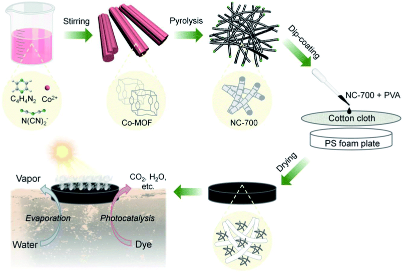 |
| | Fig. 1 Scheme of the fabrication of the bifunctional NC-x evaporator for interfacial solar-driven evaporation and the photocatalytic degradation of organic dyes (note: x stands for the calcination temperature, e.g., 700 °C; after coating, the PS foam plate was covered by the black NC-x evaporator). | |
2.3. Characterization
Scanning electron microscopy (SEM, SU8010) and transmission electron microscopy (TEM, Tecnai G2 F30) were utilized to reveal the morphology and microstructure. A surface area analyzer (Micromeritics ASAP 2460) was used to study the pore structure. The crystal structure was disclosed by X-ray diffraction (XRD) using a SmartLab-SE diffractometer, and the degree of graphitization was studied using a laser confocal Raman microscope (LabRAM HR800). X-ray photoelectron spectroscopy (XPS) was used to study the surface chemical composition and state using a spectrometer (VG ESCALAB MK II). A micro optical contact angle measurer (Dataphysics OCA15EC) was employed to record the water contact angle. A UV-Vis-NIR spectrophotometer (Lambda 750 S) was utilized to acquire the absorption spectrum. A thermal conductivity analyzer (Hot Disk, TPS 2500) was employed to measure the thermal conductivity. A UV-6100 spectrometer (METASH) was used to obtain the UV-Vis absorption spectrum. Electron paramagnetic resonance (EPR) was conducted using an EMXmicro-6/1 spectrometer. The degradation products were analyzed by high-performance liquid chromatography-mass spectroscopy (HPLC-MS, 1290-6530-Qtof). Inductively coupled plasma optical emission spectroscopy (ICP-OES) was utilized to analyze the elemental content using an Agilent ICPOES730 spectrometer.
2.4. Interfacial solar-driven vapor generation
The evaporation system consists of a solar light simulator (CEL-S500L) as the light source and an electronic balance to record the real-time water mass change (Fig. S3†). In addition, an infrared camera (DMI220) was used to monitor the surface temperature of the evaporator. The water evaporation rate (m, kg m−2 h−1) and light-to-vapor conversion efficiency (η, %) were calculated using the following equations:| | | η = m′ × hLV/(3600 × Pin) | (2) |
where Δm refers to the water mass loss in 1 h (kg), S stands for the illuminated area of the evaporator (1.134 × 10⁻³ m2), t refers to the time (1 h), m′ represents the evaporation rate minus the dark evaporation rate, hLV represents the evaporation enthalpy (kJ kg−1), and Pin refers to the irradiation intensity (kW m−2).
2.5. Photocatalytic performance test
The degradation of CR was carried out in a glass beaker containing the CR solution (75 mL, 100 ppm) and the solar evaporator with 30 mg NC-x. After static adsorption in darkness for 30 min, PMS (0.15 g L−1) was injected into the solution to initiate the reaction under 1 kW m−2 (1 sun) illumination. At intervals of 15 min, 0.7 mL solution was withdrawn and analyzed using a UV-Vis spectrophotometer. The degradation efficiency of CR was calculated using the absorbance ratio of the reaction solution to initial solution at the maximum absorption wavelength (ca. 495 nm for the CR solution). The other dye solutions applied in this work were direct red 80 (DR 80, 20 ppm), eosin Y (ES Y, 40 ppm), acid yellow 79 (AY 79, 100 ppm), amino black 10B (AB 10B, 40 ppm), and a mixture of the five studied dyes (60 ppm). In addition, the degradation of phenol was conducted using a phenol solution (30 ppm) and analyzed by high-performance liquid chromatography (HPLC, WUFENG LC-P100) at a UV wavelength of 280 nm with a mobile phase of methanol/water (60/40, v/v) at 1 mL min−1.
3. Results and discussion
3.1. Analysis of morphology and microstructure
The NC-x evaporators were facilely prepared by coating NC-x on cotton cloth, which was supported by PS foam (Fig. 1). Macroscopically, Co-MOF is a pink powder and NC-x powders are black. The NC-700/800 powders appear to be much looser than NC-500/600 (Fig. S4a†). The morphologies of Co-MOF and NC-x were characterized by SEM. As expected, Co-MOF presents a grooved microrod morphology with a mean diameter of ca. 7.6 μm (Fig. 2a, S4b and S5†). Besides, the carbon materials obtained from the different temperatures show distinct morphologies. NC-500 pyrolyzed at 500 °C inherits the microrod morphology with a rough surface (Fig. 2b and S4c†). When the temperature reaches 600 °C, there are more fine cracks grown from the microrods (Fig. 2c and S4d†). Interestingly, NC-700 derived at 700 °C is completely converted into wrinkled bamboo-like carbon tubes, which correspond to a hierarchical pore structure (Fig. 2d and S4e†). The formation of carbon tubes results from the pyrolysis of nitrogenous ligands catalyzed by metal particles. Additionally, NC-800 exhibits a similar morphology to that of NC-700, although it undergoes harsher calcination (Fig. 2e and S4f†). The mean diameter of the carbon rods/tubes declines from ca. 8.2 μm (NC-500) to 6.1 μm (NC-600), 0.72 μm (NC-700), and 0.62 μm (NC-800) (Fig. S6†). The reduced diameter of NC-600 relative to NC-500 (or NC-800 relative to NC-700) may result from the collapse of carbon at a higher temperature. Thereby, the morphology of the MOF-derived carbon is controlled by altering the calcination temperature from 500 °C to 800 °C.
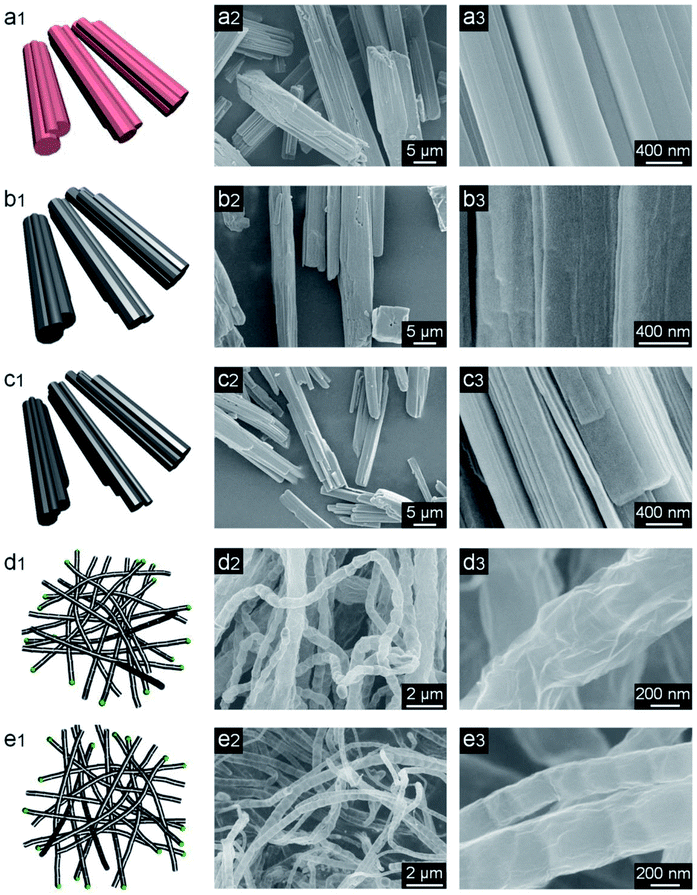 |
| | Fig. 2 Schemes (1st column) and SEM images (2nd and 3rd columns) of (a1–a3) Co-MOF, (b1–b3) NC-500, (c1–c3) NC-600, (d1–d3) NC-700, and (e1–e3) NC-800. | |
Moreover, energy-dispersive X-ray spectroscopy (EDS) was conducted to study the distribution of the elements. As shown in Fig. S7,† C, N and O as well as Co nanoparticles are uniformly dispersed in NC-700, which contributes to abundant active sites. Besides, the non-woven cotton cloth is composed of randomly interlaced cellulosic fibers with an average diameter of ca. 15 μm, leading to plentiful hydrophilic channels (Fig. S8a–c†). For the NC-700 evaporator, carbon tubes are found to well combine with cotton fibers, concurrently available for light absorption and water transport (Fig. S8d–i†).
TEM was employed to explore the microstructure of NC-700. Fig. S9a–c† show that NC-700 is composed of wrinkled bamboo-like carbon tubes and wrapped metal particles. The particles are embedded in the top of the carbon tubes, indicating the tip-growth mechanism of the carbon tubes. The carbon layer is distinctly observed at the bamboo joint with a spacing of ca. 0.38 nm (Fig. S9d†) or at the shell of metal particles with a spacing of ca. 0.36 nm (Fig. S9e†). The actual spacing is a little bigger than that of the carbon layer (ca. 0.34 nm), probably due to the doping of N atoms in the carbon layer structure. Besides, the interplanar spacing of ca. 0.20 nm indicates the (111) lattice plane of cubic cobalt (Fig. S9f†). Doped nitrogen and embedded Co particles can modulate the electronic structure of the nearby carbon layer,52 improving the catalytic activity of NC-700.
3.2. Investigation of porosity, crystal structure, and composition
The pore structures of Co-MOF and NC-x were analyzed by nitrogen adsorption/desorption at 77 K. Obviously, NC-x exhibits larger nitrogen adsorption volumes than that of Co-MOF (Fig. 3a), implying the more developed pores and larger specific surface areas of NC-x. Typically, NC-x displays type-IV adsorption curves with obvious hysteresis loops, indicating abundant micro/mesopores. Accordingly, the BET surface areas of Co-MOF and NC-500, 600, 700 and 800 are 4.4, 29.3, 26.3, 119.3 and 110.3 m2 g−1, respectively. In addition, the pore size distribution curves show that the micro/mesopores in NC-x are situated at 1.0, 3.2 and 17.2 nm (Fig. 3b). Notably, NC-700/800 possess a wider aperture distribution than those of NC-500/600, ascribed to the wrinkled carbon tubes converted from microrods. Generally, NC-700/800 possess large specific surface areas and hierarchical pore structures, which favor light trapping and water supply.
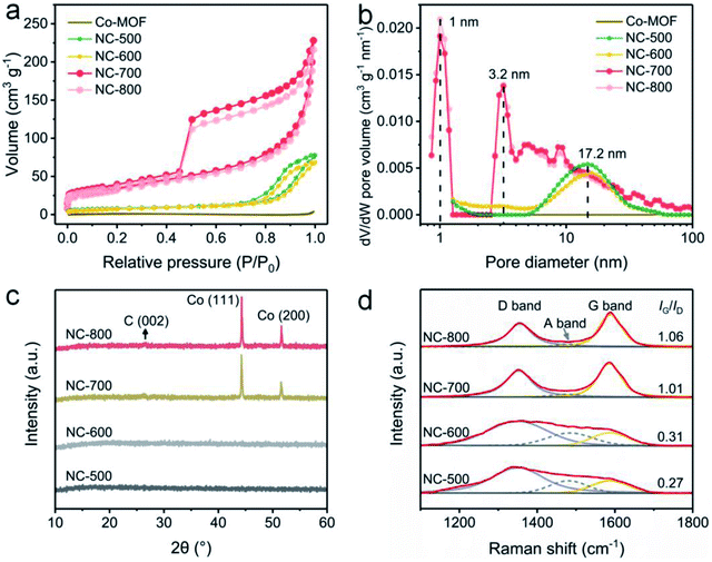 |
| | Fig. 3 (a) Nitrogen adsorption/desorption isotherms and (b) DFT pore size distribution curves of Co-MOF and NC-x. (c) XRD and (d) Raman spectra of NC-x. | |
XRD was utilized to reveal the crystalline structure. Firstly, Co-MOF displays a correct crystal structure (Fig. S10†), according to the literature.51,53 As shown in Fig. 3c, NC-500/600 exhibit an amorphous structure since no diffraction peaks are observed, while NC-700/800 possess a crystalline structure due to the emergence of peaks. Therein, the small peak situated at ca. 26.6° (Fig. S11†) results from the (002) lattice plane of graphite (PDF# 75-1621), and the two intense peaks centered on 44.3° and 51.6° are assigned to the (111) and (200) lattice planes of cubic cobalt (PDF# 89-4307), respectively. As is well known, cobalt particles act as catalysts in the formation of carbon nanotubes.54 Moreover, the graphitization degree of NC-x was investigated by Raman spectroscopy (Fig. 3d). The typical peaks located around 1354 and 1587 cm−1 are assigned to the D band and G band, respectively, while the emerging A band centered at 1480 cm−1 is due to the vibration of the edge atom.55 The proportion of G to D (IG/ID) grows from 0.27 to 1.06 as the temperature rises (500–800 °C), implying that the graphitization degree is enhanced by improving the temperature.
XPS was employed to reveal the surface chemical composition and state. Co-MOF and derived NC-x are composed of C, N, O and Co (Fig. 4a). The detailed elemental content is shown in Table S1.† In general, NC-x exhibits an increased C content and reduced N, O and Co contents as the temperature rises. Therein, NC-700 contains 95.26% C, 2.52% N, 1.97% O and 0.25% Co. As Fig. 4b shows, the high-resolution C 1s spectra are divided into C–O, C–N and C–C regions, ascribed to the peaks situated at 285.6, 283.9 and 283.5 eV, respectively.56,57 The O 1s spectra imply the presence of carbon–oxygen species in NC-x (Fig. 4c), probably due to the partial oxidation by minor oxygen during pyrolysis. The N 1s spectra are split into graphitic N (403.2 eV), pyrrolic N (400.1 eV), and pyridinic N (397.5 eV) for NC-700/800 (Fig. 4e)58 due to the pyrolysis of the ligands, i.e., pyrazine and dicyanamide. The nitrogen species, especially graphitic N, suggest the easier adsorption of PMS on adjacent carbon, thereby producing more active species for pollutant degradation.59 As for NC-500/600 and Co-MOF, the N 1s spectra are divided into N–Co and N–C owing to incomplete or no pyrolysis. Additionally, Fig. 4d depicts the different N species within the carbon matrix, which enhance the hydrophilicity of the material and serve as catalytic sites for PMS activation.60 Moreover, Fig. 4f illustrates that Co2+ is reduced to Co0 as the temperature increases, as the binding energy moves to lower values. The contents of different chemical states of C, N, O and Co are supplied in Table S2.† It is asserted that NC-700 shares similar chemical composition and state with NC-800.
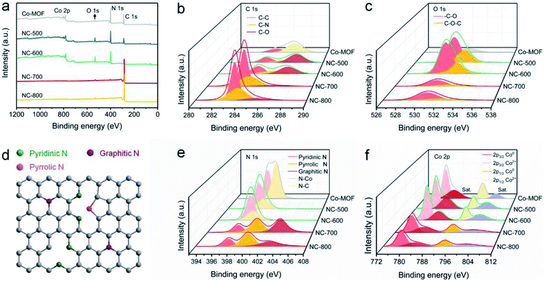 |
| | Fig. 4 XPS spectra of Co-MOF and NC-x: (a) full spectra, (b) C 1s spectra, (c) O 1s spectra, (d) scheme of N species, (e) N 1s spectra, and (f) Co 2p spectra. | |
3.3. Wettability, optical absorption, and solar-to-thermal conversion property
The wettability of an evaporator is significant in terms of water supply61 and is characterized by contact angle measurement. Initially, the contact angle of cotton cloth rapidly turns to 0° within 0.08 s (Fig. S12a, Video S1†), implying the good wettability of cotton cloth, ascribed to hydrophilic cellulose in the loose fabric. In comparison, the NC-700 evaporator (coating NC-700 on cotton cloth) gets totally wetted in 0.12 s (Fig. S12b, Video S2†), indicating the good wettability of the NC-700 evaporator due to the N/O dopants and porous structure of NC-700. Clearly, the nice wetting ability of the NC-700 evaporator means that it is available for water permeation and ROS diffusion during the solar evaporation and catalytic degradation processes.
As is well known, ideal photothermal materials are supposed to achieve efficient optical absorption as well as photo-to-thermal conversion.62 First, the optical absorption property of the NC-700 evaporator was investigated (Fig. 5a). The NC-700 evaporator exhibits broad light absorption from UV to NIR (300–2500 nm) with a high absorptivity of ca. 98%, obviously surpassing that of Co-MOF (ca. 62–70%) or cotton cloth (ca. 37–51%). As presented in Fig. 5b, the surface temperature of the NC-700 evaporator increases from 40.2 °C to 112.2 °C in 2 min under 1 sun irradiation, quicker than that of cotton (from 39.5 °C to 51.5 °C). At 10 min, the surface temperature of the NC-700 evaporator stabilizes at 112.5 °C, remarkably higher than that of cotton (54.4 °C). The results above illustrate the superior solar-to-thermal conversion capacity of the NC-700 evaporator. Supportably, Fig. 5c and d show the infrared images of cotton and the NC-700 evaporator, respectively. Similarly, the stable surface temperature of the NC-700 evaporator in the wet state (ca. 56.0 °C, Fig. S13†) is higher than that of cotton (ca. 41.0 °C).
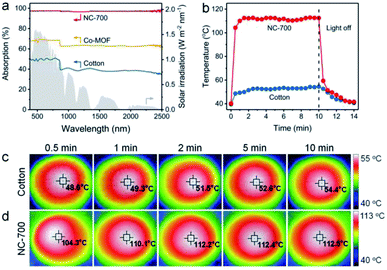 |
| | Fig. 5 (a) UV-Vis-NIR absorption spectra of cotton, Co-MOF and the NC-700 evaporator. (b) Surface temperature curves, and (c and d) infrared images of cotton and the NC-700 evaporator under 1 sun irradiation. | |
3.4. Interfacial solar-driven vapor generation
Solar-driven evaporation was monitored using a lab-made device chiefly consisting of a solar light simulator and an electronic balance (Fig. S3†). Cotton covers the upper surface and side of the PS foam to ensure efficient water permeation and mass transfer for interfacial solar evaporation and dye degradation (Fig. S14†). The mass change of the CR solution linearly depends on the illumination time (Fig. 6a). Accordingly, the evaporation rates of NC-700 without and with PMS are 2.23 and 2.20 kg m−2 h−1, respectively, significantly surpassing that of the CR solution without evaporators (blank, 0.83 kg m−2 h−1) or with cotton and PMS (PMS, 0.99 kg m−2 h−1) (Fig. 6b). Indeed, the pyrolysis temperature of NC-x makes an obvious difference to the evaporation property. The as-prepared carbon evaporator displays evaporation rates of 1.79, 1.93, 2.20 and 2.17 kg m−2 h−1 corresponding to the calcination temperatures from 500 to 800 °C (Fig. 6c). Therein, 700 °C is considered the preferred temperature because the NC-700 evaporator displays a higher evaporation rate than those of the NC-500/600 evaporators, and exhibits parallel performance to the NC-800 evaporator. Under 700 °C, wrinkled carbon tubes grow from microrods, resulting in a hierarchical pore structure, which promotes optical absorption and water transport. Moreover, the content of cobalt in NC-700 was measured to be 22.3 wt% using ICP-OES. The NC-700 evaporator after acid pickling (NC-700 immersed in 1 M HCl for 1 day) to remove the Co nanoparticles exhibits slightly inferior performance (2.03 kg m−2 h−1, Fig. S15†) compared with the pristine NC-700 evaporator. These results indicate the active role of Co nanoparticles in solar steam generation, likely related to the plasma local heating of cobalt nanoparticles under light illumination.63 In addition, the water mass losses of the CR solution in darkness within 1 h are recorded to be 243 mg (blank), 312 mg (PMS, i.e., cotton + PMS), 354 mg (NC-700) and 351 mg (NC-700 + PMS) (Fig. 6d), implying that cotton and NC-700 accelerate the water evaporation. According to the result in darkness, the evaporation enthalpy of NC-700 + PMS turns out to be 1.68 kJ g−1 (Note S1†), which decreases by 31% compared with that of blank (2.43 kJ g−1) or 11% compared to that of PMS (cotton + PMS, 1.89 kJ g−1). The reduced evaporation enthalpy of the NC-700 + PMS system or cotton + PMS system is likely related to the formation of intermediate water.64–67 As can be seen, the hydrophilic cellulose of cotton fibers and hydrophilic groups of N,O-doped porous carbon are advantageous to the formation of hydrogen bond interactions between water molecules and the evaporator, yielding bonded water. Intermediate water is further formed through hydrogen bond interactions with bonded water.
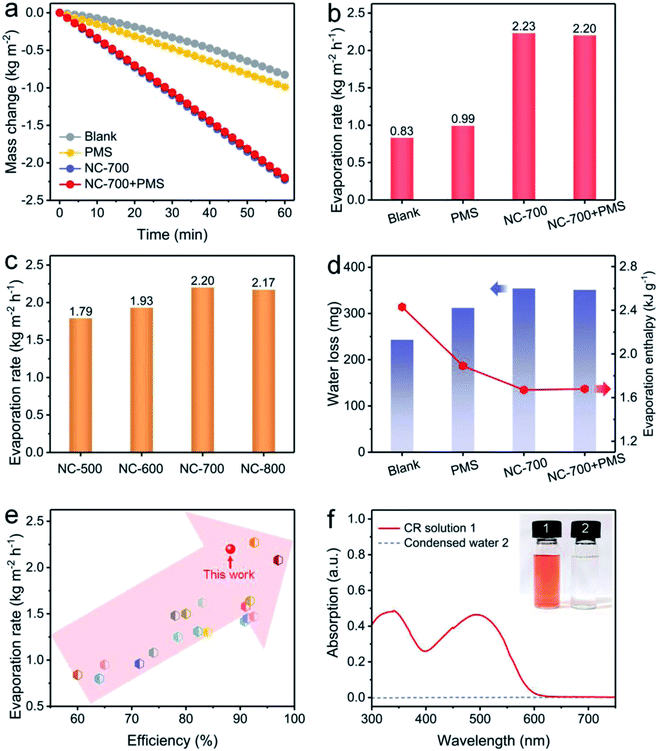 |
| | Fig. 6 (a) Water mass change and (b) evaporation rate under diverse conditions: blank (100 ppm of the CR solution under 1 kW m−2 irradiation), PMS (adding cotton and 0.15 g L−1 PMS), NC-700 (adding the NC-700 evaporator), and NC-700 + PMS (adding the NC-700 evaporator and 0.15 g L−1 PMS). (c) Evaporation rate using the NC-x evaporator under 1 sun irradiation. (d) Water loss of the CR solution in darkness and the evaporation enthalpy. (e) Comparison of the performance of the NC-700 evaporator with some previous works. (f) UV-Vis curves of the CR solution and condensed water. | |
More importantly, the NC-700 evaporator exhibits remarkable performance compared to some previous works (Fig. 6e and Table S3†), including TiO2/nickel foam (1.25 kg m−2 h−1),68 carbonized mushrooms (1.48 kg m−2 h−1),69 3D graphene networks (1.64 kg m−2 h−1),70 and Ag@polydopamine wooden flower (2.08 kg m−2 h−1).71 The conversion efficiency of the NC-700 evaporator is calculated to be 88.2% (eqn (2) in the Experimental section). Additionally, the NC-700 evaporator exhibits a low thermal conductivity (0.08 W m−1 K−1), contributing to a low heat loss calculated to be 19.9% (Note S2†). Supportably, an apparent spray is observed under illumination (Video S3†). The condensed water collected from 100 ppm of the CR solution becomes colourless, and the removal efficiency of CR is more than 99.9% on the basis of the UV-Vis curves (Fig. 6f).
Furthermore, the influences of PMS and CR concentrations on evaporation performance were investigated. The evaporation rate using the NC-700 evaporator stabilizes at ca. 2.2 kg m−2 h−1 when the PMS concentration changes from 0 to 0.30 g L−1 (Fig. 7a) or the CR concentration varies from 50 to 200 ppm (Fig. 7b), showing the negligible impacts of PMS and CR concentration on the evaporation performance. Moreover, the NC-700 evaporator exhibits stable evaporation rates for water polluted with various dyes, namely direct red 80 (DR 80), eosin Y (ES Y), acid yellow 79 (AY 79), amino black 10B (AB 10B), and a mixture of the five studied dyes (Fig. 7c). The condensed freshwater from dye-polluted water appears to be colorless, and the dye removal efficiency exceeds 99.9% according to the UV-Vis spectra (Fig. 7d), implying the universality of the NC-700 evaporator for the treatment of various dye-polluted water sources.
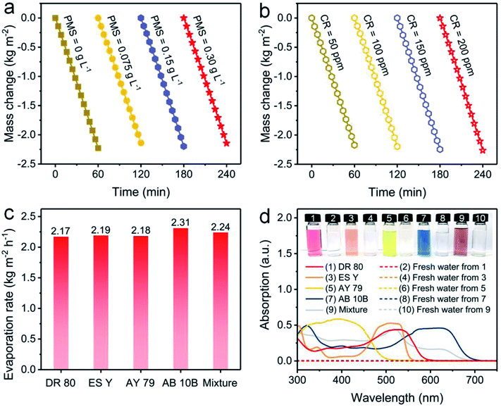 |
| | Fig. 7 Water mass changes of dye-polluted water with (a) different PMS concentrations or (b) different CR concentrations under 1 sun irradiation. (c) Evaporation rates of the NC-700 evaporator in water polluted with different dyes. (d) UV-Vis absorption curves and photographs of diverse dye solutions and condensed freshwater. | |
3.5. Photocatalytic degradation performance
The photocatalytic performance of NC-700 for PMS activation was assessed by CR degradation (Fig. 8a). Therein, the NC-700 evaporator exhibits an insignificant adsorption of CR, since the concentration of CR only reduces by ca. 5% in darkness. Besides, CR hardly degrades under 1 sun irradiation (blank), and the NC-700 evaporator could not efficiently degrade CR since merely ca. 12.5% of CR is removed in 90 min (NC-700). By contrast, PMS plays a noticeable role in CR degradation under visible light irradiation, as ca. 60% of CR is eliminated in 90 min (PMS), where PMS quickly decomposes to form ROS activated by thermal energy and visible light. Notably, when concurrently adding the NC-700 evaporator and PMS (NC-700 + PMS), the degradation efficiency of CR reaches ca. 82.2% in 15 min and ca. 96.6% in 90 min, implying the powerful catalytic capability of NC-700 for PMS activation. Additionally, the first-order kinetic rate constant was calculated according to the formula [ln(C/C0) = −kt], where C and C0 represent the real-time and initial concentrations of CR, respectively, t refers to the irradiation time, and k stands for the rate constant. Consequently, the rate constant of NC-700 + PMS (0.078 min−1) clearly outstrips that of PMS (0.015 min−1), showing that the NC-700 evaporator markedly accelerates the reaction rate (Fig. 8b and S16†). Supportably, the color of the CR solution barely changes in the blank condition (Fig. S17†) or only on adding the NC-700 evaporator (Fig. 8c), while it becomes darker after adding PMS (Fig. 8d). In contrast, the solution turns almost colorless after concurrently adding the NC-700 evaporator and PMS (Fig. 8e). As a matter of fact, the NC-700 evaporator exhibits comparable performance with many advanced carbon-/metal-based catalysts (Table S4†). Hence, water evaporation and dye degradation are simultaneously and efficiently fulfilled in the NC-700 + PMS system. Furthermore, HPLC-MS was employed to infer the degradation intermediates and pathway of CR (Fig. S18†). Initially, the sulfonate group and amidogen are cleaved to generate the intermediate (m/z value of 555). Second, the azo bond (–N![[double bond, length as m-dash]](https://www.rsc.org/images/entities/char_e001.gif) N–) or the –C–C– bond is broken to form the intermediate products (m/z = 417 and 313). Afterwards, the intermediates are decomposed and oxidized into smaller molecules (m/z = 237, 207, 159, 180, 145 and 117), and finally mineralized to CO2, H2O and inorganic oxidized N.
N–) or the –C–C– bond is broken to form the intermediate products (m/z = 417 and 313). Afterwards, the intermediates are decomposed and oxidized into smaller molecules (m/z = 237, 207, 159, 180, 145 and 117), and finally mineralized to CO2, H2O and inorganic oxidized N.
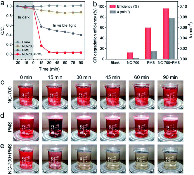 |
| | Fig. 8 (a) The CR degradation efficiency within 90 min in different conditions. (b) The CR degradation efficiency and rate constant in different conditions. (c–e) Photographs of 100 ppm CR solution (75 mL) with NC-700 (30 mg), PMS (0.15 g L−1) and NC-700 + PMS under 1 sun irradiation. | |
The influences of catalyst dosage and PMS and CR concentration on the degradation property were studied (Fig. S19†). When the NC-700 dosage increases from 20 to 50 mg, the degradation efficiency of CR improves from 94.1% to 98.1%, and the rate constant rises from 0.056 to 0.081 min−1 (Fig. S19a and b†). Besides, the degradation efficiency of CR is boosted by raising the PMS concentration from 0.075 to 0.15 g L−1, but the removal is not further enhanced when the PMS concentration reaches 0.3 g L−1 (Fig. S19c and d†), indicating that excessive PMS is unnecessary or even detrimental to ROS generation. Additionally, as the CR concentration rises from 50 to 200 ppm, the removal efficiency of CR gradually reduces from 98.7% to 63.3%, and the rate constant decreases from 0.093 to 0.015 min−1 (Fig. S19e and f†). Supportably, the fitting curves of the rate constant are depicted in Fig. S20.†
The effect of catalyst species on the degradation property was studied. As shown in Fig. 9a and b, NC-x derived from different temperatures exhibit a similar CR degradation efficiency at 90 min; however, NC-700/800 display higher rate constants (0.078 and 0.068 min−1, respectively) than those of NC-500/600 (0.051 and 0.052 min−1, respectively), ascribed to the larger specific surface area and higher graphitization degree of NC-700/800. Besides, NC-700 after acid pickling shows a lower degradation efficiency for CR and a lower rate constant (85.2% and 0.028 min−1, respectively) than those of pristine NC-700 (Fig. 9c and d), indicating the positive effect of Co nanoparticles on PMS activation. After 5 cycles, the CR degradation efficiency remains above 95%, and the rate constant slightly reduces from 0.078 min−1 to ca. 0.060 min−1 (Fig. S21†). Overall, the NC-700 evaporator exhibits favorable stability for CR degradation, possibly ascribed to the nearly neutral CR + PMS solution (pH = ca. 7) and the carbon layer that protects the Co nanoparticles from leaching in acidic conditions.
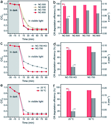 |
| | Fig. 9 The influences of (a and b) pyrolysis temperature, (c and d) acid pickling, and (e and f) reaction temperature on the degradation efficiency of CR and the rate constant. | |
More importantly, as a photothermal material, NC-700 effectively converts light into thermal energy, which elevates the water temperature (Fig. S22†), which is supposed to be the key factor to synergistically promote PMS activation. To confirm this speculation, we conducted a model catalytic degradation experiment of CR in the presence of PMS and NC-700 powder at 25 °C and 50 °C (Fig. 9e and f). As expected, the rate constant of CR at 50 °C is up to ca. 0.13 min−1, enhanced by 225% compared to that at 25 °C (ca. 0.04 min−1). Notably, as shown in Fig. S23,† the rate constant of CR using the NC-700 + PMS system under visible light irradiation (0.078 min−1) is obviously higher than that in the dark (0.033 min−1), which can be ascribed to the higher temperature caused by the photothermal material NC-700. That is to say, further thermal energy converted from sunlight improves PMS activation and facilitates mass transfer to accelerate the catalytic degradation of pollutants. Similar phenomena were observed in a previous work.72
The NC-700 evaporator was applied to water polluted with various dyes to confirm its catalytic universality. As shown in Fig. 10a, the dye-containing solutions exhibit significant absorption in the range of 300–700 nm at first, but they exhibit little absorption of visible light after the reaction. As a result, the degradation efficiency of DR 80, ES Y, AY 79, AB 10B and the mixture of the five dyes is over 90%, and the rate constants exceed 0.05 min−1 (Fig. 10b). Supportably, the dye solutions after degradation become nearly colorless, proving the wide applicability of the NC-700 solar evaporator in the degradation of various dyes (Fig. 10c). It should be noted that the NC-700 evaporator + PMS system also works well in the photocatalytic degradation of phenol, a typical volatile organic compound (VOC), as shown in Fig. S24.†
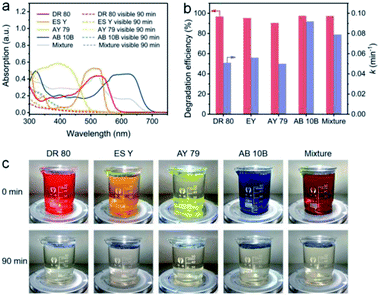 |
| | Fig. 10 (a) UV-Vis spectra, (b) dye degradation efficiency and rate constant, and (c) photographs of water polluted with different dyes before and after degradation. | |
3.6. Investigation of reactive oxygen species and possible generation pathways
To identify the ROS in the NC-700 + PMS system, a classical radical quenching experiment was conducted (Fig. 11a). Radicals (SO4˙−, ˙OH, O2˙−) and non-radicals (1O2) are regarded as usual ROS in PMS activation.73 Typically, we utilized ethanol as an efficient scavenger of both SO4˙− and ˙OH, and employed tert-butanol as a quencher of ˙OH. After adding excess tert-butanol (0.5 M), the CR removal efficiency slightly declines to 94.5%, indicating that ˙OH plays an insignificant role in PMS activation. Besides, the CR degradation efficiency decreases to 84.2% after adding ethanol, suggesting the existence of SO4˙−. Furthermore, the degradation efficiency of CR is dramatically reduced to 27.2% after using benzoquinone to quench O2˙−, implying the leading role of O2˙− in the degradation of CR. As we know, 1O2 serves as a non-radical species, which could be generated by N-doped carbon,74 and L-histidine can be applied to examine 1O2. The removal efficiency of CR in the presence of L-histidine declines to 58.2%, stating that 1O2 is also an important species in the system.
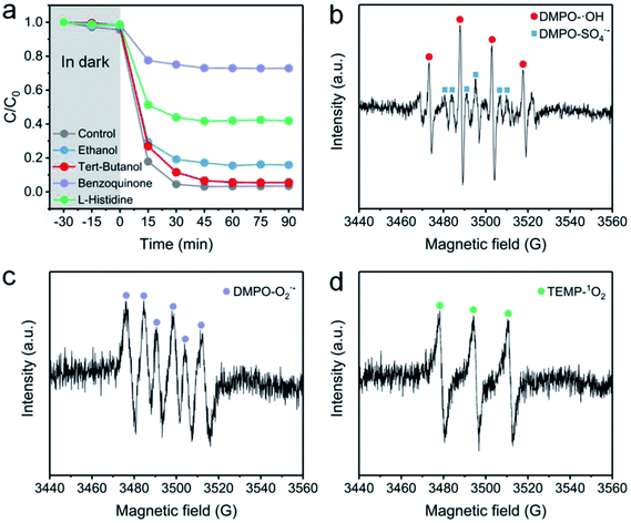 |
| | Fig. 11 (a) The effect of radical scavengers on the CR degradation efficiency: [ethanol] = [tert-butanol] = 0.4 M and [benzoquinone] = [L-histidine] = 0.01 M. (b–d) EPR spectra with the addition of DMPO or TEMP. Reaction condition: [PMS] = 0.15 g L−1 (0.4 mM), catalyst = 0.4 g L−1, [DMPO] = 0.4 M, and [TEMP] = 0.3 M. | |
EPR measurement was further conducted to prove the existence of ROS. Herein, DMPO serves as a spin-trapping agent of both SO4˙− and ˙OH in an aqueous medium, and also acts as a trapping agent of O2˙− in ethanol. Besides, TEMP is used to trap 1O2 in ethanol. As illustrated in Fig. 11b, a four-line signal with an intensity ratio of ca. 1![[thin space (1/6-em)]](https://www.rsc.org/images/entities/char_2009.gif) :
:![[thin space (1/6-em)]](https://www.rsc.org/images/entities/char_2009.gif) 2
2![[thin space (1/6-em)]](https://www.rsc.org/images/entities/char_2009.gif) :
:![[thin space (1/6-em)]](https://www.rsc.org/images/entities/char_2009.gif) 2
2![[thin space (1/6-em)]](https://www.rsc.org/images/entities/char_2009.gif) :
:![[thin space (1/6-em)]](https://www.rsc.org/images/entities/char_2009.gif) 1 indicates the existence of ˙OH, and the surrounding six-line signal confirms the presence of SO4˙−. As shown in Fig. 11c, the intense six-line signal for DMPO-O2˙− implies the generation of O2˙−. Moreover, the triplet signal with the intensity ratio of 1
1 indicates the existence of ˙OH, and the surrounding six-line signal confirms the presence of SO4˙−. As shown in Fig. 11c, the intense six-line signal for DMPO-O2˙− implies the generation of O2˙−. Moreover, the triplet signal with the intensity ratio of 1![[thin space (1/6-em)]](https://www.rsc.org/images/entities/char_2009.gif) :
:![[thin space (1/6-em)]](https://www.rsc.org/images/entities/char_2009.gif) 1
1![[thin space (1/6-em)]](https://www.rsc.org/images/entities/char_2009.gif) :
:![[thin space (1/6-em)]](https://www.rsc.org/images/entities/char_2009.gif) 1 demonstrates the existence of 1O2 (Fig. 11d). Based on the above results, the possible pathways of radical and non-radical production are proposed (eqn (3)–(10)).72,75
1 demonstrates the existence of 1O2 (Fig. 11d). Based on the above results, the possible pathways of radical and non-radical production are proposed (eqn (3)–(10)).72,75
| | | Co2+ + HSO5− → Co3+ + SO4˙− + OH− | (4) |
| | | Co3+ + HSO5− → Co2+ + SO5˙− + H+ | (5) |
| | | SO4˙− + H2O → SO42− + ˙OH + H+ | (6) |
| | | C–π + HSO5− → C–π+ + SO4˙− + OH− | (7) |
| | | C–π+ + HSO5− → C–π + SO5˙− + H+ | (8) |
| | | HSO5− + ˙OH → HSO4− + O2˙− + H+ | (9) |
| |  | (10) |
3.7. Mechanism of the integrated interfacial solar-driven evaporation and the advanced oxidation process
The mechanism of the interfacial solar-driven evaporation and photocatalytic degradation of organic dyes by NC-700 is proposed (Fig. 12). NC-700 presents as wrinkled bamboo-like carbon tubes wrapping Co nanoparticles, leading to a hierarchical pore structure and high specific surface area, which not only favour light absorption and water transport for solar evaporation but also expose abundant catalytic sites for PMS activation. For the interfacial solar evaporation, the NC-700 evaporator supported by PS foam displays efficient photothermal conversion, fast water permeation and low heat loss, so as to facilely acquire freshwater from non-potable water. For the photocatalytic degradation of dyes, the Co nanoparticles embedded in the carbon tubes are conducive to preventing metal corrosion and can donate electrons to the carbon lattice via the intimately interacting metal–carbon interface, increasing the electron density and elevating the Fermi level of the external carbon layer for enhanced catalytic behaviour.76 Meanwhile, the N species, especially pyridinic-N and graphitic-N, play an active role in PMS activation by modulating the electronic structure of adjacent carbon atoms for better PMS adsorption.77 That is, PMS molecules are efficiently activated by NC-700 and produce SO4˙−, ˙OH, and O2˙− radicals and 1O2 non-radicals. Afterwards, dye molecules (e.g., CR) are attacked by ROS and decompose into their intermediates, CO2 and H2O, realizing the purification of the mother liquor. Innovatively, the heat converted from light by the photothermal material simultaneously accelerates the PMS activation, implying the effective synergy of the interfacial solar evaporation and dye degradation by the AOP method.
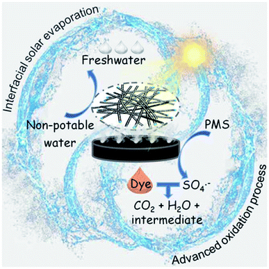 |
| | Fig. 12 Scheme for the mechanism of the interfacial solar-driven evaporation and the advanced oxidation process by the bifunctional NC-700 evaporator under visible light irradiation. | |
3.8. Outdoor interfacial solar evaporation and catalytic degradation
An outdoor installation was designed to verify the performance of NC-700 for realistic evaporation and dye degradation (Fig. 13a). The NC-700 evaporator floats on a CR solution in a container, which is put on a supporting plate within an evaporation chamber and covered by a vapor condenser (Fig. S25†). A large-scale NC-700 evaporator (diameter = 16 cm) is prepared by the dip coating of NC-700 on cotton cloth, which is supported by PS foam (Fig. 13b and S26†). The condensed water slides down and is collected by a bottom pipe, while the degraded solution is gathered by an upper pipe to regularly monitor the degradation efficiency of CR. In practice, the device was placed in our campus from 8:00 to 20:00 (July, 2021). It is obvious that the CR solution becomes almost colorless after degradation, and the condensed water is distinctly observed with increasing irradiation time (Fig. 13c–g and S27†). The maximal irradiation intensity and temperature in the day are 0.58 kW m−2 and 37.5 °C, respectively (Fig. 13h). The system shows a maximum freshwater production rate of 0.74 kg m−2 h−1 at 14:00, and achieves a cumulative water production of 5.1 kg m−2 over 12 h irradiation (Fig. 13i). Thus, water generated by a 1 m2 device (5.1 kg) satisfies the basic water demand of two adults in one day (5 kg). The degradation efficiency of CR reaches 79.2% after 1 h and 96.4% after 12 h (Fig. 13j and S28†), stating the great catalytic performance of NC-700. Besides, the cost of the NC-700 evaporator was calculated to be ¥ 7.5 (Table S5†), signifying the feasible large-scale production of the NC-700 evaporator. The above results prove the practical application potential of NC-700 in solar-driven evaporation and wastewater remediation.
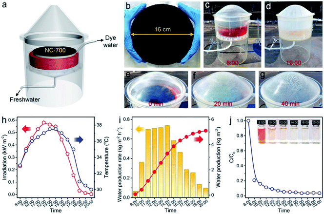 |
| | Fig. 13 (a) Scheme of the outdoor interfacial solar evaporation and catalytic degradation device. (b) Photograph of the large-sized NC-700 evaporator (diameter = 16 cm). (c and d) Photographs showing the device with the NC-700 evaporator at 8:00 and 19:00, respectively. (e–g) Photographs showing the evaporation evolution in 40 min. (h) Curves of the real-time irradiation intensity and temperature. (i) Record of the freshwater production rate and accumulated production. (j) Curve of CR degradation evolution with time. | |
4. Conclusion
To sum up, we have fabricated a bifunctional evaporator using nitrogen/cobalt-doped porous carbon as a solar absorber and cotton cloth as a substrate. The porous carbon derived from Co-MOF exhibits wrinkled bamboo-like carbon tubes wrapped around Co nanoparticles, which is different from the microrod morphology of its precursor. The large specific surface area (119.3 m2 g−1) and abundant N,Co,O-dopants are conducive to the efficient light absorption, great wettability, and plentiful active sites of NC-700. Besides, the cotton cloth composed of hydrophilic cellulosic fibers provides sufficient interspace to ensure fast water permeation and mass transfer. As a result, the NC-700 evaporator not only shows remarkable evaporation performance (2.2 kg m−2 h−1) but also exhibits notable dye degradation properties through PMS activation. This work provides an ingenious approach to synergistically realize freshwater production and sewage purification. Additionally, introducing more hydrophilic groups into carbon materials to improve the water evaporation rate via the reduction of water evaporation enthalpy will be conducted in a future work.
Author contributions
P. H.: conceptualization, investigation, data curation, methodology, visualization and writing. H. B., Z. F., L. H., N. L., and B. C.: investigation, data curation and writing. R. N. and J. G.: conceptualization, investigation, data curation, methodology, visualization, writing and supervision.
Conflicts of interest
The authors declare that they have no known competing financial interests or personal relationships that could have appeared to influence the work reported in this paper.
Acknowledgements
The present work is supported by the National Natural Science Foundation of China (No. 51903099 and 22102059), 100 Talents Program of Hubei Provincial Government, Huazhong University of Science and Technology (No. 3004013134 and 2021XXJS036), and the Innovation and Talent Recruitment Base of New Energy Chemistry and Device (No. B21003). We are grateful to the Analytical and Testing Centre of HUST for access to their facilities.
References
- M. Gao, C. K. Peh, L. Zhu, G. Yilmaz and G. W. Ho, Adv. Energy Mater., 2020, 10, 2000925 CrossRef CAS.
- T. Gao, X. Wu, Y. Wang, G. Owens and H. Xu, Sol. RRL, 2021, 5, 2100053 CrossRef CAS.
- N. Li, L. Qiao, J. He, S. Wang, L. Yu, P. Murto, X. Li and X. Xu, Adv. Funct. Mater., 2021, 31, 2008681 CrossRef CAS.
- K. Xu, C. Wang, Z. Li, S. Wu and J. Wang, Adv. Funct. Mater., 2021, 31, 2007855 CrossRef CAS.
- T. Ding, Y. Zhou, W. L. Ong and G. W. Ho, Mater. Today, 2021, 42, 178–191 CrossRef CAS.
- J. He, N. Li, S. Wang, S. Li, C. Wang, L. Yu, P. Murto and X. Xu, J. Mater. Chem. A, 2022 10.1039/d2ta00594h.
- S. Meng, X. Zhao, C. Tang, P. Yu, R. Bao, Z. Liu, M. Yang and W. Yang, J. Mater. Chem. A, 2020, 8, 2701–2711 RSC.
- A. H. Elsheikh, S. W. Sharshir, M. K. A. Ali, J. Shaibo, E. M. A. Edreis, T. Abdelhamid, D. Chun and H. O. Zhang, Sol. Energy, 2019, 177, 561–575 CrossRef CAS.
- N. Liu, L. Hao, B. Zhang, R. Niu, J. Gong and T. Tang, Energy Environ. Mater., 2022, 5, 617–626 CrossRef CAS.
- B. Zhang, P. W. Wong and A. K. An, Chem. Eng. J., 2022, 430, 133054 CrossRef CAS.
- F. Li, N. Li, S. Wang, L. Qiao, L. Yu, P. Murto and X. Xu, Adv. Funct. Mater., 2021, 31, 2104464 CrossRef CAS.
- Z. Xu, Z. Li, Y. Jiang, G. Xu, M. Zhu, W. C. Law, K. T. Yong, Y. Wang, C. Yang, B. Dong and F. Xing, J. Mater. Chem. A, 2020, 8, 25571–25600 RSC.
- Y. Wang, X. Wu, T. Gao, Y. Lu, X. Yang, G. Y. Chen, G. Owens and H. Xu, Nano Energy, 2021, 79, 105477 CrossRef CAS.
- B. Shao, Y. Wang, X. Wu, Y. Lu, X. Yang, G. Y. Chen, G. Owens and H. Xu, J. Mater. Chem. A, 2020, 8, 11665–11673 RSC.
- J. Li, X. Zhou, Y. Jing, H. Sun, Z. Zhu, W. Liang and A. Li, ACS Appl. Mater. Interfaces, 2021, 13, 12181–12190 CrossRef CAS PubMed.
- M. S. Irshad, X. Wang, M. S. Abbasi, N. Arshad, Z. Chen, Z. Guo, L. Yu, J. Qian, J. You and T. Mei, ACS Sustainable Chem. Eng., 2021, 9, 3887–3900 CrossRef CAS.
- L. Hao, N. Liu, R. Niu, J. Gong and T. Tang, Sci. China Mater., 2022, 65, 201–212 CrossRef CAS.
- T. Hu, K. Chen, L. Li and J. Zhang, J. Mater. Chem. A, 2021, 9, 17502–17511 RSC.
- L. Li and J. Zhang, Nano Energy, 2021, 81, 105682 CrossRef CAS.
- L. Zhu, M. Gao, C. K. N. Peh and G. W. Ho, Nano Energy, 2019, 57, 507–518 CrossRef CAS.
- X. Li, J. Li, J. Lu, N. Xu, C. Chen, X. Min, B. Zhu, H. Li, L. Zhou, S. Zhu, T. Zhang and J. Zhu, Joule, 2018, 2, 1331–1338 CrossRef CAS.
- Q. Zhao, C. Du, Y. Jia, J. Yuan, G. Song, X. Zhou, S. Sun, C. Zhou, L. Zhao and S. Yang, Chem. Eng. J., 2020, 387, 124131 CrossRef CAS.
- X. Wu, Z. Wu, Y. Wang, T. Gao, Q. Li and H. Xu, Adv. Sci., 2021, 8, 202002501 Search PubMed.
- H. Bai, N. Liu, L. Hao, P. He, C. Ma, R. Niu, J. Gong and T. Tang, Energy Environ. Mater., 2021 DOI:10.1002/eem2.12235.
- L. Hao, N. Liu, H. Bai, P. He, R. Niu and J. Gong, J. Colloid Interface Sci., 2022, 608, 840–852 CrossRef CAS.
- C. Zhang, Y. Shi, L. Shi, H. Li, R. Li, S. Hong, S. Zhuo, T. Zhang and P. Wang, Nat. Commun., 2021, 12, 998 CrossRef CAS PubMed.
- J. Ren, Y. Ding, J. Gong, J. Qu and R. Niu, Energy Environ. Mater., 2022 DOI:10.1002/eem2.12376.
- Q. Zhang, W. Xu and X. Wang, Sci. China Mater., 2018, 61, 905–914 CrossRef CAS.
- M. Zou, Y. Zhang, Z. Cai, C. Li, Z. Sun, C. Yu, Z. Dong, L. Wu and Y. Song, Adv. Mater., 2021, 33, 2102443 CrossRef CAS PubMed.
- S. Dong, Y. Zhao, J. Yang, X. Liu, W. Li, L. Zhang, Y. Wu, J. Sun, J. Feng and Y. Zhu, Appl. Catal., B, 2021, 291, 120127 CrossRef CAS.
- R. Djellabi, L. Noureen, V. D. Dao, D. Meroni, E. Falletta, D. D. Dionysiou and C. L. Bianchi, Chem. Eng. J., 2022, 431, 134024 CrossRef CAS.
- D. Fan, Y. Lu, H. Zhang, H. Xu, C. Lu, Y. Tang and X. Yang, Appl. Catal., B, 2021, 295, 120285 CrossRef CAS.
- L. Shi, Y. Shi, C. Zhang, S. Zhuo, W. Wang, R. Li and P. Wang, Energy Technol., 2020, 8, 2000456 CrossRef CAS.
- D. Hao, Y. Yang, B. Xu and Z. Cai, ACS Sustainable Chem. Eng., 2018, 6, 10789–10797 CrossRef CAS.
- S. Yan, H. Song, Y. Li, J. Yang, X. Jia, S. Wang and X. Yang, Appl. Catal., B, 2022, 301, 120820 CrossRef CAS.
- S. Giannakis, K. Y. A. Lin and F. Ghanbari, Chem. Eng. J., 2021, 406, 127083 CrossRef CAS.
- J. Lee, U. von Gunten and J. H. Kim, Environ. Sci. Technol., 2020, 54, 3064–3081 CrossRef CAS PubMed.
- C. Chen, T. Ma, Y. Shang, B. Gao, B. Jin, H. Dan, Q. Li, Q. Yue, Y. Li, Y. Wang and X. Xu, Appl. Catal., B, 2019, 250, 382–395 CrossRef CAS.
- Q. Gan, Y. Xiao, C. Li, H. Peng, T. Zhang and M. Ye, Chemosphere, 2021, 280, 130618 CrossRef CAS PubMed.
- Y. Wang, S. Hui, S. Zhan, R. Djellabi, J. Li and X. Zhao, Chem. Eng. J., 2020, 381, 122563 CrossRef CAS.
- H. Fu, S. Ma, P. Zhao, S. Xu and S. Zhan, Chem. Eng. J., 2019, 360, 157–170 CrossRef CAS.
- M. Zhang, R. Luo, C. Wang, W. Zhang, X. Yan, X. Sun, L. Wang and J. Li, J. Mater. Chem. A, 2019, 7, 12547–12555 RSC.
- Z. Huang, M. Shen, J. Liu, J. Ye and T. Asefa, J. Mater. Chem. A, 2021, 9, 14841–14850 RSC.
- R. Zhou, H. Song, D. Zu, S. Pan, Y. Wang, F. Wang, Z. Li, Y. Shen and C. Li, Sep. Purif. Technol., 2022, 282, 119990 CrossRef CAS.
- Z. Xiong, Y. Jiang, Z. Wu, G. Yao and B. Lai, Chem. Eng. J., 2021, 421, 127863 CrossRef CAS.
- C. Wang, J. Kim, V. Malgras, J. Na, J. Lin, J. You, M. Zhang, J. Li and Y. Yamauchi, Small, 2019, 15, 1900744 CrossRef PubMed.
- M. Hao, M. Qiu, H. Yang, B. Hu and X. Wang, Sci. Total Environ., 2021, 760, 143333 CrossRef CAS PubMed.
- P. He, L. Hao, N. Liu, H. Bai, R. Niu and J. Gong, Chem. Eng. J., 2021, 423, 130268 CrossRef CAS.
- S. Ma, W. Qarony, M. I. Hossain, C. T. Yip and Y. H. Tsang, Sol. Energy Mater. Sol. Cells, 2019, 196, 36–42 CrossRef CAS.
- J. Ye, C. Li, L. Wang, Y. Yan, Y. Wang and J. Dai, Sep. Purif. Technol., 2021, 258, 117669 CrossRef CAS.
- P. Jensen, S. R. Batten, B. Moubaraki and K. S. Murray, J. Solid State Chem., 2001, 159, 352–361 CrossRef CAS.
- H. Li, J. Tian, Z. Zhu, F. Cui, Y. Zhu, X. Duan and S. Wang, Chem. Eng. J., 2018, 354, 507–516 CrossRef CAS.
- L. Ma, R. Wang, Y. Li, X. Liu, Q. Zhang, X. Dong and S. Zang, J. Mater. Chem. A, 2018, 6, 24071–24077 RSC.
- W. Niu, S. Pakhira, K. Marcus, Z. Li, J. L. Mendoza-Cortes and Y. Yang, Adv. Energy Mater., 2018, 8, 1800480 CrossRef.
- S. H. Kim, V. D. Dao, L. L. Larina, K. D. Jung and H. S. Choi, Chem. Eng. J., 2016, 283, 1285–1294 CrossRef CAS.
- P. He, Y. Wu, H. Chen, Z. Zhu, H. Liu, J. Gao and H. Xu, J. Alloys Compd., 2019, 813, 152192 CrossRef.
- N. Liu, L. Hao, B. Zhang, R. Niu, J. Gong and T. Tang, Sustainable Energy Fuels, 2020, 4, 5522–5532 RSC.
- Y. Wu, M. Lu, Y. Li, P. He, S. B. Maddine, J. Gao and J. Yao, Chem.–Asian J., 2018, 13, 3274–3280 CrossRef CAS PubMed.
- G. Wang, S. Chen, X. Quan, H. Yu and Y. Zhang, Carbon, 2017, 115, 730–739 CrossRef CAS.
- Y. Ito, Y. Tanabe, J. Han, T. Fujita, K. Tanigaki and M. Chen, Adv. Mater., 2015, 27, 4302–4307 CrossRef CAS PubMed.
- K. Li, M. Gao, Z. Li, H. Yang, L. Jing, X. Tian, Y. Li, S. Li, H. Li, Q. Wang, J. S. Ho, G. W. Ho and P. Y. Chen, Nano Energy, 2020, 74, 104875 CrossRef CAS.
- M. Gao, L. Zhu, C. K. Peh and G. W. Ho, Energy Environ. Sci., 2019, 12, 841–864 RSC.
- Y. Zhao, D. You, W. Yang, H. Yu, Q. Pan and S. Song, Environ. Sci.: Water Res. Technol., 2022, 8, 151–161 RSC.
- Y. Guo, H. Lu, F. Zhao, X. Zhou, W. Shi and G. Yu, Adv. Mater., 2020, 32, 1907061 CrossRef CAS PubMed.
- F. Zhao, Y. Guo, X. Zhou, W. Shi and G. Yu, Nat. Rev. Mater., 2020, 5, 388–401 CrossRef.
- X. Zhou, Y. Guo, F. Zhao, W. Shi and G. Yu, Adv. Mater., 2020, 32, 2007012 CrossRef PubMed.
- X. Zhou, F. Zhao, Y. Guo, B. Rosenberger and G. Yu, Sci. Adv., 2019, 5, eaaw5484 CrossRef CAS PubMed.
- X. Chen, C. Meng, Y. Wang, Q. Zhao, Y. Li, X. M. Chen, D. Yang, Y. Li and Y. Zhou, ACS Sustainable Chem. Eng., 2020, 8, 1095–1101 CrossRef CAS.
- N. Xu, X. Hu, W. Xu, X. Li, L. Zhou, S. Zhu and J. Zhu, Adv. Mater., 2017, 29, 1606762 CrossRef PubMed.
- K. Kim, S. Yu, C. An, S. W. Kim and J. H. Jang, ACS Appl. Mater. Interfaces, 2018, 10, 15602–15608 CrossRef CAS PubMed.
- S. Chen, Z. Sun, W. Xiang, C. Shen, Z. Wang, X. Jia, J. Sun and C. J. Liu, Nano Energy, 2020, 76, 104998 CrossRef CAS.
- S. Zhang, H. Gao, X. Xu, R. Cao, H. Yang, X. Xu and J. Li, Chem. Eng. J., 2020, 381, 122670 CrossRef CAS.
- W. Ma, N. Wang, Y. Fan, T. Tong, X. Han and Y. Du, Chem. Eng. J., 2018, 336, 721–731 CrossRef CAS.
- X. Duan, H. Sun, Z. Shao and S. Wang, Appl. Catal., B, 2018, 224, 973–982 CrossRef CAS.
- C. H. Wu, J. T. Lin and K. Y. A. Lin, J. Colloid Interface Sci., 2018, 517, 124–133 CrossRef CAS PubMed.
- X. Duan, J. Kang, W. Tian, H. Zhang, S. H. Ho, Y. A. Zhu, Z. Ao, H. Sun and S. Wang, Appl. Catal., B, 2019, 256, 117795 CrossRef CAS.
- Y. Liu, X. Chen, Y. Yang, Y. Feng, D. Wu and S. Mao, Chem. Eng. J., 2019, 358, 408–418 CrossRef CAS.
|
| This journal is © The Royal Society of Chemistry 2022 |
Click here to see how this site uses Cookies. View our privacy policy here.  * and
Jiang
Gong
 *
*


![[double bond, length as m-dash]](https://www.rsc.org/images/entities/char_e001.gif) N–) or the –C–C– bond is broken to form the intermediate products (m/z = 417 and 313). Afterwards, the intermediates are decomposed and oxidized into smaller molecules (m/z = 237, 207, 159, 180, 145 and 117), and finally mineralized to CO2, H2O and inorganic oxidized N.
N–) or the –C–C– bond is broken to form the intermediate products (m/z = 417 and 313). Afterwards, the intermediates are decomposed and oxidized into smaller molecules (m/z = 237, 207, 159, 180, 145 and 117), and finally mineralized to CO2, H2O and inorganic oxidized N.


![[thin space (1/6-em)]](https://www.rsc.org/images/entities/char_2009.gif) :
:![[thin space (1/6-em)]](https://www.rsc.org/images/entities/char_2009.gif) 2
2![[thin space (1/6-em)]](https://www.rsc.org/images/entities/char_2009.gif) :
:![[thin space (1/6-em)]](https://www.rsc.org/images/entities/char_2009.gif) 2
2![[thin space (1/6-em)]](https://www.rsc.org/images/entities/char_2009.gif) :
:![[thin space (1/6-em)]](https://www.rsc.org/images/entities/char_2009.gif) 1 indicates the existence of ˙OH, and the surrounding six-line signal confirms the presence of SO4˙−. As shown in Fig. 11c, the intense six-line signal for DMPO-O2˙− implies the generation of O2˙−. Moreover, the triplet signal with the intensity ratio of 1
1 indicates the existence of ˙OH, and the surrounding six-line signal confirms the presence of SO4˙−. As shown in Fig. 11c, the intense six-line signal for DMPO-O2˙− implies the generation of O2˙−. Moreover, the triplet signal with the intensity ratio of 1![[thin space (1/6-em)]](https://www.rsc.org/images/entities/char_2009.gif) :
:![[thin space (1/6-em)]](https://www.rsc.org/images/entities/char_2009.gif) 1
1![[thin space (1/6-em)]](https://www.rsc.org/images/entities/char_2009.gif) :
:![[thin space (1/6-em)]](https://www.rsc.org/images/entities/char_2009.gif) 1 demonstrates the existence of 1O2 (Fig. 11d). Based on the above results, the possible pathways of radical and non-radical production are proposed (eqn (3)–(10)).72,75
1 demonstrates the existence of 1O2 (Fig. 11d). Based on the above results, the possible pathways of radical and non-radical production are proposed (eqn (3)–(10)).72,75


