 Open Access Article
Creative Commons Attribution 3.0 Unported Licence
Dimensionally stable multication-crosslinked poly(arylene piperidinium) membranes for water electrolysis†
Xiuqin
Wang
 and
Rob G. H.
Lammertink
 *
*
Soft Matter, Fluidics and Interfaces, Faculty of Science and Technology, MESA+ Institute for Nanotechnology, University of Twente, Enschede, 7522 NB, The Netherlands. E-mail: R.G.H.Lammertink@utwente.nl; Fax: (+31)534-894-611
First published on 4th March 2022
Abstract
Cross-linking is a widely employed process to improve the dimensional stability of anion exchange membranes (AEMs). However, crosslinking often comes at the expense of ion exchange capacity and ionic conductivity. To address this “trade-off” problem, we introduce a multication crosslinker composed of two piperidinium groups and a flexible alkyl chain to fabricate novel crosslinked poly(arylene piperidinium)-based AEMs (C-IL-x). It is found that multication crosslinkers can promote the fabrication of micro-phase separated morphology and construct highly efficient ion conducting pathways inside the membrane. Compared to the non-crosslinked AEM, the conductivity and dimensional stability of crosslinked C-IL-x AEMs were improved simultaneously. The highest ionic conductivity of the crosslinked C-IL-x AEMs reaches up to 95 mS cm−2 at 80 °C. In addition, alkaline water electrolysis using the C-IL-100 AEM (100 refers to the expected crosslinking degree) exhibits a high current density of 880 mA cm−2 at 2.2 V in 1 M KOH solution with Ni-based catalysts, which confirms that multication crosslinked AEMs are promising for application in alkaline water electrolysis.
1. Introduction
Hydrogen is currently regarded as a crucial energy carrier and is hailed as the “ultimate energy source of the 21st century”.1 The majority of commercially available hydrogen is prepared by steam reforming of natural gas, partial oxidation of methane, and coal gasification. These processes generate massive amounts of greenhouse gases and atmospheric pollutants.2 To make hydrogen economically and environmentally competitive to fossil fuels, research on efficient and cost-effective hydrogen production via water electrolysis has attracted substantial attention. Traditional water electrolysis suffers from a low hydrogen production efficiency, high energy consumption, high overpotential and corrosion.2 Compared with traditional water electrolysis using porous diaphragms, polyelectrolyte membrane-based water electrolysis has many advantages, e.g. high electrolyzer lifetimes, high efficiencies, reduced hydrogen production costs, and low maintenance expenditures.3,4 Protonexchange membrane-based water electrolyzers (PEMWEs) have been commercialized and show excellent performance in ultrapure water due to a high conversion efficiency (up to 70%).5–7 However, PEMWEs rely on expensive precious-metal catalysts (IrO2 and Pt) and perfluorinated membranes and result in a high cost of water electrolyzer devices.8–11As an alternative, anion exchange membrane-based water electrolyzers (AEMWEs) attract great attention since these use inexpensive platinum group metal-free electrocatalysts (e.g., Ni-, Fe-, or Co-based) which reduces the cost of the water electrolyzer devices and efficiently produces pressurized hydrogen.12 Despite its promise, the development of AEMWEs is still limited by the poor performance of the anion exchange membranes (AEMs). AEMs work as solid-state electrolytes between the cathode and the anode to avoid mixing of hydrogen and oxygen products while enabling OH− transport.13 The ionic conductivity of AEMs is much lower than that of PEM due to the lower mobility of OH− ions compared to protons.14,15 Besides, most AEMWEs showed a dramatic decline in performance after prolonged operation due to the degradation of the AEMs under alkaline conditions.16 Thus, it is urgent to develop alkali-stable and highly conductive AEMs for water electrolysis.
To improve the conductivity of the AEMs, approaches such as increasing the ion exchange capacity (IEC) are suggested. Philip et al. found that ionic conductivity is proportional to IEC.17 However, the inherent “trade-off” between the ionic conductivity and membrane swelling (i.e., a high IEC usually leads to a high-water uptake and swelling ratio) limits the method of merely increasing IEC.18,19 Another approach to increase conductivity is to incorporate multication into the AEMs.20 Zhu et al. developed multication side chain AEMs for fuel cell application.21 A highest conductivity of 99 mS cm−1 was observed at room temperature for the as-prepared AEMs. However, the water uptake and swelling ratio of AEM could reach up to 172 wt% and 36% at 80 °C, respectively. The balance between the dimensional stability and ionic conductivity has become a challenging issue. Micro-phase segregated AEMs, containing hydrophilic ion-conducting channels in a more hydrophobic matrix, present a promising approach for developing AEMs with high conductivity and low swelling.22,23 However, complex processes are often required to construct micro-phase separated morphologies in the AEMs.24,25 Covalent crosslinking is an alternative approach that could effectively restrain the water swelling of AEMs. Crosslinkers such as dialdehyde, diol, and dithiol have been used in AEMs via thermal or UV activation.26,27 Lin et al. developed crosslinked side-chain-type AEMs via thermal crosslinking.28 They found that the introduction of crosslinks reduced the IEC and thereby the conductivity of the AEMs. Thus, there is a need to investigate crosslinking strategies that improve the dimensional stability of AEMs without sacrificing other performances.
Chen et al. presented crosslinking AEMs based on poly(biphenyl piperidinium) and functionalized poly(phenyl ether).29 Although high conductivity and low swelling were obtained, the backbone with aryl ether-bonds increases the risk of degradation under alkaline conditions.30 Besides the backbone, the stability of the cationic group is also a concern. Nowadays, most of the AEMs are based on polymers tethered with benzyl trimethylammonium or alkyl-tethered ammonium cations. These cationic groups are more prone to be attacked by the hydroxide ions via nucleophilic substitution, Hofmann elimination, and ylide formation.31,32 Hofmann elimination would not occur with benzyl trimethylammonium cations due to the absence of β-H. Although the alkyl-tethered ammonium cations such as piperidinium showed good chemical stability in some reports, they still have the risk of Hofmann elimination due to the existence of β-H.33 Lee et al. systematically studied the alkaline stability of 24 representative N-heterocyclic ammonium groups (NHAs).33 The typical NHAs with a symmetric structure, possess an electron-donating group which weakens the electronegativity of the ionic group and provides higher alkaline stability compared to asymmetric NHAs. Recently, we investigated the effect of N-cyclic cations on the performance of poly(phenylalkylene)-based AEMs.34 The results showed that piperidinium-functionalized AEMs with an ether-bond-free backbone show good alkaline stability. However, the application of the poly(phenylalkylene)-based AEMs is limited by the rather low conductivity (68.7 mS cm−1 at 80 °C) and poor dimensional stability.
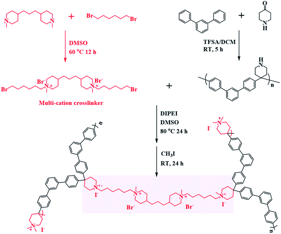
In this study, we introduce a tailored crosslinking method for poly(phenylalkylene)-based AEMs. A series of novel multication-crosslinked poly(phenylalkylene) AEMs were prepared to further improve the performance of the membrane, as shown in Scheme 1 and Fig. 1. The twisted backbone of C-IL-x is foldable, as validated by Bae,35 which can shorten the distance between ionic groups and thereby improve hydroxide ion mobility inside the membrane. The crosslinking is effective to constrain the swelling of the AEMs. The multication crosslinker has two NHAs that provide fixed charge groups for ionic conduction, and thus the introduction of the crosslinking structure not only improves the dimensional stability but also enhances the conductivity. The design of an ether-bond-free structure and NHA cation is expected to result in good alkaline stability. The as-prepared AEMs were assembled in an AEMWE to investigate their performance (e.g., ionic conductivity and long-term stability). The effect of operating parameters (KOH concentration and temperature) on the performance of alkaline water electrolysis was investigated.
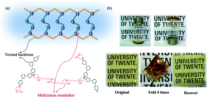 | ||
| Fig. 1 (a) The configurations and schematic diagram of the flexible conducting channels in the C-IL-x AEM. (b) A folding-unfolding test utilizing the crosslinked C-IL-100 AEMs. | ||
2. Experimental
2.1 Materials
4,4′-Trimethylenebis(1-methyl piperidine) (>98%), 1,6-dibromohexane (96%), 4-piperidone monohydrate hydrochloride (PMH, 98%), potassium carbonate (K2CO3, 99%), iodomethane (CH3I, 99%), dichloromethane (DCM), diethyl ether (AR), dimethyl sulfoxide (DMSO, AR), potassium hydroxide (KOH, AR), sodium hydroxide (NaOH, AR), sodium nitrate (NaNO3, AR), acetone (AR), hydrochloric acid (HCl, AR), and deuterated dimethyl sulfoxide (DMSO-d6, 99.96 atom% D) were purchased from Sigma-Aldrich and were used without purification. m-Terphenyl (99%), trifluoromethane sulfonic acid (TFSA, >98%), and N,N-diisopropylethylamine (DIPEI, >99%) were purchased from TCI Chemical Co. Acros. Deionized (DI) water (18.2 MΩ, 0.2 μm filtered) was used for membrane treatments and measurements throughout this work.2.2 Preparation of AEMs
![[thin space (1/6-em)]](https://www.rsc.org/images/entities/char_2009.gif) :
:![[thin space (1/6-em)]](https://www.rsc.org/images/entities/char_2009.gif) 5, indicating a theoretical 20% crosslinking. The synthetic procedure for C-IL-20 is described as follows: m-TPN (0.20 g) and IL (0.04 g) were completely dissolved in DMSO (5 mL) to form a homogeneous solution. Then DIPEI (10 μL) used as an acid-binding agent to promote the deprotonation of m-TPN and promote the following functionalization reaction was added to the above solution.15,36 A small amount of precipitate was formed in the solution, but it disappeared after shaking the mixture for several minutes (Fig. S1†). This may be caused by the incompatibility between the polymer solution and liquid DIPEI. When it reacted with m-TPN the product became soluble, and the precipitate disappeared. The final solution (ab. 5 mL) was then poured onto the glass plate and moved to an oven at 80 °C for 24 h to crosslink and evaporate the solvent. The resulting thickness of the crosslinked membranes was 50 ± 5 μm as recorded by using a digital micrometer. The remaining piperidine groups were functionalized by methyl iodide solution. The membrane was then immersed in iodomethane/methanol solution to convert the piperidine groups to piperidinium groups. The quaternization reaction was performed at room temperature (RT) in the dark for 24 h, after which the membrane was washed several times with water to remove excess iodomethane. The resulting membranes were immersed in 1 M KOH at RT for 48 h to exchange the negative ions with hydroxyl, followed by washing with DI water and storing in DI water before measurements.
5, indicating a theoretical 20% crosslinking. The synthetic procedure for C-IL-20 is described as follows: m-TPN (0.20 g) and IL (0.04 g) were completely dissolved in DMSO (5 mL) to form a homogeneous solution. Then DIPEI (10 μL) used as an acid-binding agent to promote the deprotonation of m-TPN and promote the following functionalization reaction was added to the above solution.15,36 A small amount of precipitate was formed in the solution, but it disappeared after shaking the mixture for several minutes (Fig. S1†). This may be caused by the incompatibility between the polymer solution and liquid DIPEI. When it reacted with m-TPN the product became soluble, and the precipitate disappeared. The final solution (ab. 5 mL) was then poured onto the glass plate and moved to an oven at 80 °C for 24 h to crosslink and evaporate the solvent. The resulting thickness of the crosslinked membranes was 50 ± 5 μm as recorded by using a digital micrometer. The remaining piperidine groups were functionalized by methyl iodide solution. The membrane was then immersed in iodomethane/methanol solution to convert the piperidine groups to piperidinium groups. The quaternization reaction was performed at room temperature (RT) in the dark for 24 h, after which the membrane was washed several times with water to remove excess iodomethane. The resulting membranes were immersed in 1 M KOH at RT for 48 h to exchange the negative ions with hydroxyl, followed by washing with DI water and storing in DI water before measurements.
For comparison, m-TPN was functionalized by CH3I to obtain non-crosslinked AEMs (m-TPNPiQA), as shown in Scheme S1,† which was studied in our previous work.34 The reaction steps were as follows. m-TPN (2.00 g), K2CO3 (2.20 g), DMSO (40 mL) and CH3I (1.80 mL) were mixed in a flask. The reaction was carried out at RT for 24 h in the dark. The product was obtained by pouring the reaction solution into diethyl ether to precipitate. The raw product was washed with ethanol/water solution and dried under vacuum for 24 h. The membrane was made by casting and solvent evaporation as well.
2.3 Characterization
The chemical structures of the synthesized m-TPN polymers and IL were identified by 1H NMR spectroscopy using a 400 MHz NMR instrument (Bruker ASCEND™). DMSO-d6 and tetramethylsilane (TMS) were used as the solvent and internal standard, respectively. Fourier transform infrared spectroscopy (FT-IR) spectra were collected using a PerkinElmer UATR spectrometer in the range of 4000–400 cm−1 with resolutions of 4 cm−1 and 16 scans. Scanning electron microscope (SEM) images were collected on a JEOL JSM-6010LA InTouchScope™ instrument with an accelerating voltage of 5.0 kV. Prior to SEM imaging, the membrane was dried in a vacuum oven at 30 °C and then coated with a 5 nm Pt layer. The surface microstructure of the AEMs was further investigated by tapping-mode atomic force microscopy (AFM) (Bruker Dimension® Icon™) with a TESPA-V2 nanosensor at RT. Small-angle X-ray scattering (SAXS) was performed on a SAXS SYSTEM (XENOCS, France). A Zwick Z5.0 mechanical tester was used to measure the mechanical properties of the AEMs in the wet state at RT. The crosshead speed of the tester was 10 mm min−1. The membrane samples were cut into dumbbell shapes with an active area of 20 mm × 4 mm. The thermal stability of the AEMs was investigated by using a thermogravimetric analyzer (PerkinElmer TGA 4000), operating from RT to 800 °C at a heating rate of 10 °C min−1 under a nitrogen atmosphere.2.4 Membrane characteristics
 | (1) |
 | (2) |
The WU (%) of the AEMs was determined by using the following equation:
 | (3) |
The in-plane SR (%) of the AEMs was calculated using the following equation:
 | (4) |
 | (5) |
The Arrhenius activation energy (Ea) for ion conduction was calculated from the slope of ln![[thin space (1/6-em)]](https://www.rsc.org/images/entities/char_2009.gif) σ versus 1/T.
σ versus 1/T.
 | (6) |
2.5 Membrane electrode assembly and AEMWE performance
The water electrolysis tests were carried out by using C-IL-100 (50 μm) and m-TPNPiQA (53 μm) as the AEMs. Before preparing the membrane electrode assembly (MEA), the AEMs were soaked in a 1 M KOH solution overnight to exchange the negative ions with the hydroxide form and rinsed with DI water to remove the residual KOH. Then the AEM is sandwiched between the cathode and anode and hot-pressed at 10 MPa at 50 °C for 10 min. The cathode consists of a nickel fiber paper coated with a NiFeCO catalyst and the anode consists of a stainless-steel fiber paper coated with a NiFe2O4 catalyst (Dioxide Materials, US). The catalyst loading is 2 mg cm2 for each electrode. The active area of the MEA is 1.0 × 1.0 cm2.The fabricated MEA was then assembled into an AEMWE cell (Fig. S2†) where the endplates, with embedded flow channels, are made of corrosion-resistant nickel. The 1 M KOH aqueous solution flow rate was 2 mL min−1 and the temperature was controlled at RT, 50 °C, and 80 °C. Before collecting the polarization curves and electrochemical impedance spectroscopy (EIS), the AEMWE cell was activated for 30 min at a current density of 10–50 mA cm−2. The polarization curves were then recorded by scanning the potential from 1.2 V to 2.5 V with a scan rate of 5 mV s−1. EIS was studied to evaluate the resistance cell in the through-plane direction. The impedance measurement was performed under constant voltage mode (1.5 V, 1.8 V, and 2.1 V) with a frequency range from 105 Hz to 1 Hz and an AC amplitude of 10 mV. The alkaline durability test in 1 M KOH was operated at a constant current of 100 mA cm−2 for C-IL-100 and 10 mA cm−2 for m-TPNPiQA at 50 °C with a flow rate of 5 mL min−1.
3. Results and discussion
3.1 Preparation and characterization of crosslinked AEMs
m-TPN was prepared via Friedel–Crafts type polycondensation according to our previous work.34Fig. 3a shows the 1H NMR spectrum of m-TPN, and the characteristic peaks appearing between 7.0 and 8.2 ppm are assigned to the proton peaks of the benzene rings. The peaks around 2.8 ppm (H3) and 3.2 ppm (H2) correspond to the proton resonance from the piperidine ring. The characteristic signal at 8.3 ppm (H1) belongs to the proton resonance from the –NH group.15 The location of the peaks is consistent with the results from previous work, which indicates that the m-TPN polymer was synthesized successfully. The chemical structure of the iodomethane functionalized m-TPNPiQA polymer is shown in Fig. S4.†The 1H-NMR spectrum of the multication crosslinker IL is presented in Fig. S3(b).† The peaks from 3.3–3.6 ppm (H1,6,8) are attributed to the –CH2– that connects to the N or Br atom. The signals located at 3.1 ppm (H7) are ascribed to the proton resonance from –CH3 of the piperidinium groups and the peaks around 1.3 ppm (H4,11,12) correspond to the signals from the alkyl chains. The peak areas at different positions were integrated and the proportion of the peak areas were consistent with the ratio of hydrogen atoms in the polymer. For example, the ratio of the integral area of H7 to H3,4,11,12 is equal to 1![[thin space (1/6-em)]](https://www.rsc.org/images/entities/char_2009.gif) :
:![[thin space (1/6-em)]](https://www.rsc.org/images/entities/char_2009.gif) 2.34, which is consistent with the theoretic value of 1
2.34, which is consistent with the theoretic value of 1![[thin space (1/6-em)]](https://www.rsc.org/images/entities/char_2009.gif) :
:![[thin space (1/6-em)]](https://www.rsc.org/images/entities/char_2009.gif) 2.33, indicating that the multication crosslinker was synthesized successfully.
2.33, indicating that the multication crosslinker was synthesized successfully.
The crosslinking density of the C-IL-x AEMs was adjusted by controlling the molar ratio of IL to the m-TPN polymer. As shown in Fig. 1b, the polymer solution became a gel after crosslinking. Although the twisted ether-free backbone is composed of rigid aromatic rings, the resulting cross-linked membranes are extremely flexible. Notably, the membrane maintained its flexibility after being folded four times and then unfolded into its original state. In addition, the SEM image of C-IL-100 (Fig. S5†) showed a smooth membrane.
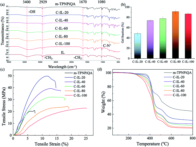
The chemical structure of the crosslinked C-IL-x AEMs was confirmed by FT-IR spectroscopy, as shown in Fig. 2a. The broad vibration band at 3400 cm−1 is attributed to water. The C-IL-100 AEM with the highest IEC or/and WU has an obvious water peak. The signals around 2929 and 1670 cm−1 are associated with the stretching vibration of –CH2–, which shows an enhanced intensity after the introduction of the multication crosslinker. The peak at 1080 cm−1 corresponds to the bending vibration of C–N+ from ammonium groups, indicating the successful cross-linking reaction.18
All the crosslinked AEMs show a high gel fraction in DMSO as shown in Fig. 2b, indicating that the crosslinking reaction was carried out successfully. The gel fraction increases with increasing addition of the multication crosslinker except for the C-IL-100 membrane (86.7 ± 2.4%) which shows a slightly lower gel fraction than that of C-IL-80 (91.2 ± 3.3%). Possibly the concentration of the multication crosslinker is too high which results in an incomplete reaction with m-TPN. The gel fraction of C-IL-20 is lower than 50% since some of the multication crosslinker may be used for connecting the polymer chains to increase the molecular weight rather than actual crosslinking.
3.2 IEC, thermal and mechanical properties of the crosslinked AEMs
IEC is an important parameter that represents the number of charged groups in the membrane. As listed in Table 1, the non-crosslinked m-TPNPiQA membrane shows an IECtitr value of 2.54 mmol g−1. The crosslinked C-IL-x AEMs do not sacrifice IEC since the multication crosslinker contains two cationic groups that even enhances the IEC. The IECtitr of C-IL-20, C-IL-40, C-IL-60, C-IL-80, and C-IL-100 membranes were measured to be 2.76, 2.79, 2.83, 2.85, and 2.99 mmol g−1, respectively. These values are near the theoretical values, IECtheo, that range from 2.85 to 3.33 mmol g−1. The possible reason for the slightly lower experimental values is that the functionalization of the crosslinked AEMs was carried out by the immersion method, during which some of the piperidine groups were not fully functionalized.37| Samples | IEC (mmol g−1) | WU (%) | SR (%) | Conductivity (mS cm−1) | ||||
|---|---|---|---|---|---|---|---|---|
| Theo.a | Titr.b | 20 °C | 80 °C | 20 °C | 80 °C | 30 °C | 80 °C | |
| a Theoretical values were calculated via the ratio of the m-TPN polymer and multication crosslinker. b Experimental values were obtained via titration. | ||||||||
| m-TPNPiQA | 2.66 | 2.54 | 52.3 | 65.2 | 21.1 | 25.7 | 28.8 | 68.7 |
| C-IL-20 | 2.85 | 2.76 ± 0.05 | 16.5 ± 2.4 | 26.3 ± 4.5 | 5.4 ± 2.6 | 8.4 ± 1.3 | 30.7 ± 0.6 | 75.6 ± 1.4 |
| C-IL-40 | 3.01 | 2.79 ± 0.08 | 22.7 ± 3.9 | 32.0 ± 1.7 | 12.8 ± 1.5 | 16.5 ± 1.6 | 31.8 ± 1.2 | 80.8 ± 3.2 |
| C-IL-60 | 3.14 | 2.83 ± 0.06 | 32.1 ± 4.5 | 53.7 ± 2.3 | 17.0 ± 1.3 | 22.5 ± 1.3 | 34.2 ± 0.1 | 82.1 ± 1.5 |
| C-IL-80 | 3.24 | 2.85 ± 0.10 | 44.2 ± 4.1 | 56.7 ± 2.8 | 18.7 ± 2.7 | 24.1 ± 1.2 | 35.6 ± 0.7 | 87.9 ± 2.7 |
| C-IL-100 | 3.33 | 2.99 ± 0.16 | 66.7 ± 2.2 | 97.0 ± 5.9 | 27.7 ± 3.9 | 35.9 ± 1.7 | 39.5 ± 0.4 | 94.6 ± 2.0 |
The mechanical stability of the AEM is one of the important parameters for applications in water electrolysis. Fig. 2c and Table S1† show the mechanical properties of non-crosslinked m-TPNPiQA and multication crosslinked C-IL-x AEMs. Compared to the non-crosslinked m-TPNPiQA membrane, all the crosslinked C-IL-x membranes obtained a higher tensile strength and elongation at break, indicating that introducing multication crosslinking into the AEMs is effective to improve the mechanical properties of the membranes. Compared to the crosslinked polymers, the relatively low molecular weight of m-TPNPiQA may be responsible for the lower mechanical properties. For the crosslinked AEMs, C-IL-20 has the highest tensile strength (49.77 MPa) and Young's modulus (781.49 MPa), while C-IL-100 shows the lowest tensile strength (22.91 MPa). Due to the plasticization of water,38 the elongation at break of C-IL-100 (25.25%) was higher than that of C-IL-20 (14.70%) and even higher than that of the reported crosslinked poly(4-vinylphenol)-based, poly(phenylene oxide)-based, and polymers of intrinsic microporosity-based AEMs.39–41 Therefore, the incorporation of a multication crosslinker in AEMs could improve the tensile strength and overcome the trade-off between the IEC and mechanical properties.
The thermal stability of the C-IL-x AEMs in the halogen form was investigated by TGA, as presented in Fig. 2d. The initial weight loss around 275 °C can be attributed to the decomposition of the alkyl chain and cationic groups. It is observed that the initial decomposition temperature decreased with the increasing content of the multication crosslinker. m-TPNPiQA without a crosslinker shows an initial decomposition temperature of 360 °C and is more stable than the crosslinked AEMs. The weight loss starting at 470 °C can be attributed to the decomposition of the rigid polymer backbone. The results show that all the crosslinked AEMs are stable up to 250 °C, indicating that the membranes could meet the requirements for the application of water electrolysis.
3.3 Morphology
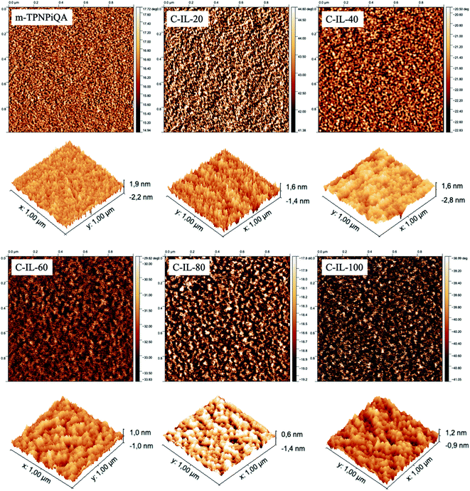
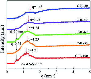
The morphology of AEMs plays an important role in the formation of effective ion conduction channels. The morphology of m-TPNPiQA was characterized by SAXS and transmission electron microscopy (TEM) in our previous work,34 while the surface morphology of crosslinked C-IL-x AEMs was characterized by AFM, as shown in Fig. 3. The darker area represents the hydrophilic ionic domains which contain the ionic groups, while the lighter area belongs to more hydrophobic domains. After introducing the multication crosslinker into the AEMs, the microphase separation morphology of the membranes become obvious and well-organized. In particularly, C-IL-100 exhibits a strongly microphase separated morphology due to its high IEC, indicating that the introduction of a hydrophilic multication crosslinker into the m-TPN could promote the formation of hydrophilic/hydrophobic micro-phase separation. Well-developed domains forming continuous percolating ion transport channels are favorable for improving ionic conductivity in the AEMs and will be discussed below. In addition, all the AEMs display a root-mean-square surface roughness below 3 nm, indicating that the AEMs have smooth surfaces.SAXS was used to investigate the bulk morphology of the crosslinked AEMs. Fig. 4 shows the scattered intensity with respect to the scattering vector (q). The cross-linked AEMs demonstrated obvious micro-phase separation peaks. According to Bragg's equation (d = 2π/q), the d-spacing of the AEMs was calculated to be in the range of 4.5–5.2 nm. In our previous work, the non-crosslinked m-TPNPiQA membrane showed a d-spacing of 1.85 nm,34 which is much lower than that of C-IL-x AEMs. This can be attributed to the introduction of multications that promote the aggregation of the ions, thereby enhancing micro-phase separation.21,42,43 Notably, with increasing content of the multication crosslinker, a larger domain size is observed. Besides, with the increasing content of the multication crosslinker, there is another peak appearing around 0.64 nm−1 for C-IL-60, C-IL-80 and C-IL-100. This peak may come from the incompletely reacted multication crosslinker which works as a side chain of poly(phenylalkylene)s that may self-assemble. These results further confirmed the contribution of multications to ion aggregation. Given the results from AFM and SAXS, it can be concluded that the flexible multication crosslinker plays an important role in microstructure formation and enhanced ionic conduction through the AEMs.44
3.4 WU, SR and conductivity
Fig. S6† and Table 1 show the WU and SR of the AEMs in the OH− form as a function of temperature. The WU (52.3%) and SR (22.1%) of the non-crosslinked m-TPNPiQA AEM at 20 °C were slightly higher than most of the C-IL-x AEMs except C-IL-100. By increasing the expected crosslinking degree or IEC values, the WU of C-IL-x AEMs increased from 26.3% to 97.0% and the SR varied from 8.5% to 35.7% at 80 °C. The swelling ratio of the crosslinked AEMs mainly relies on the IEC rather than the actual crosslinking degree (represented in Fig. 2b by the gel fraction). The IEC increases whereas the crosslinking degree saturates at a higher content of the crosslinker. A similar phenomenon can be observed in other multication crosslinked AEMs.44 The WU and SR of C-IL-x (x = 20, 40, 60, and 80) were relatively low except for C-IL-100, for which the increase in charge by the crosslinker and incomplete crosslinking led to swelling. Therefore, it can be concluded that the trade-off between IEC and dimensional stability can be solved by introducing a multication crosslinker with a proper crosslinking degree into the AEMs.41,45Ionic conductivity forms a crucial property of ion exchange membranes for their potential performance in water electrolysis. High conductivity and a low swelling ratio are required for the application of AEMs. Table 1 and Fig. 5a show the hydroxide conductivity of the as-prepared AEMs in the OH− form. The hydroxide conductivities of the membranes displayed a common upward trend with temperature elevation due to the increased mobility of ions at elevated temperatures. The conductivity of the crosslinked C-IL-x AEMs ranges from 30.7 to 94.6 mS cm−1 at 30–80 °C. It is clear that increasing the content of the multication crosslinker is helpful to improve the conductivity of the AEMs. This is attributed to the increased IEC or crosslinking degree of C-IL-100, which is beneficial to promote the aggregation of ionic groups giving a micro-phase separated structure, as confirmed by the results from AFM and SAXS (Fig. 3 and 4). Compared with non-crosslinked m-TPNPiQA membranes (Table 1), the conductivity of crosslinked C-IL-x membranes did not decline, confirming that the introduction of multication crosslinkers do not sacrifice the conductivity. The conductivities of the C-IL-x AEMs showed an approximate Arrhenius-type temperature dependence (Fig. 5b).39 The apparent activation energy (Ea) estimated from the slopes of the ln![[thin space (1/6-em)]](https://www.rsc.org/images/entities/char_2009.gif) σ (OH−) vs. 1/T plots was calculated to be 15.7–16.7 kJ mol−1, suggesting that the ion migration in the C-IL-x AEMs occurs via hopping processes between coordination sites.46,47
σ (OH−) vs. 1/T plots was calculated to be 15.7–16.7 kJ mol−1, suggesting that the ion migration in the C-IL-x AEMs occurs via hopping processes between coordination sites.46,47
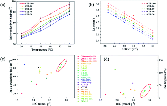 | ||
| Fig. 5 (a) The hydroxide conductivity of the fully hydrated C-IL-x AEMs. (b) Arrhenius plots of the C-IL-x AEMs. The Ea of C-IL-x (20, 40, 60, 80, and 100) are 16.14 ± 0.07 kJ mol−1, 16.69 ± 0.09 kJ mol−1,15.74 ± 0.04 kJ mol−1, 15.84 ± 0.17 kJ mol−1, and 15.98 ± 0.19 kJ mol−1, respectively. (c) Comparison of hydroxide conductivity and (d) SR as a function of IEC at 80 °C.15,35,50–53 | ||
The application of AEMWEs requires the AEM material to have high conductivity and a low SR, which could minimize the overall cell voltage and maintain structural integrity.15,48,49 Thus, the hydroxide conductivity and SR of the C-IL-x AEMs in this study were compared with some typical polyphenylene-based AEMs reported in the literature, as shown in Fig. 5c. It was found that the C-IL-x AEMs exhibited a lower SR and higher ionic conductivity than most reported AEMs under the same condition. This is because the introduction of multication crosslinkers results in a microphase separated morphology. As discussed above, the multication crosslinker could facilitate ion aggregation and provide more pronounced microphase separation, resulting in the formation of efficient ion transport channels for high ion conduction. The crosslinking constrains the SR and avoids low conductivity caused by ion dilution. These results confirm that the crosslinked C-IL-x AEMs are attractive candidates for water electrolysis applications.
3.5 Alkaline stability
The development of cationic polymers for AEMs with excellent alkaline stability is a considerable challenge in materials chemistry. In our previous work, the alkaline stability of m-TPNPiQA was tested in 1 M, 2 M, and 5 M NaOH solution at 80 °C for 240 h. Less than 6% of IEC was lost after the stability test, indicating good stability of m-TPNPiQA.34 Here, the alkaline stability of the C-IL-x AEMs was systematically investigated by monitoring the variation in the chemical structure after alkaline exposure via FT-IR spectroscopy. Fig. 6a compares the FT-IR spectra of the C-IL-100 AEM before and after immersing the membranes into 1 M KOH at 50 °C for 1200 h. The two new absorption bands around 1420 cm−1 and 1600 cm−1 were attributed to the degradation product, which can be observed for C-IL-100 and other C-IL-x AEMs (x = 20, 40, 60, and 80). Based on our previous studies on the degradation mechanism of m-TPNPiQA, these two new peaks may be attributed to the –CH![[double bond, length as m-dash]](https://www.rsc.org/images/entities/char_e001.gif) CH2 groups which were generated from the β-Hofmann elimination reaction of the piperidinium groups.34 The change in OH− conductivity of C-IL-100 AEMs during ex situ durability testing is shown in Fig. 6b. The conductivities of C-IL-100 decreased slightly to 97.8% after treating with 1 M KOH at 50 °C for 1200 h. These results indicate that the combination of the ether-bond-free structure and multication crosslinker is beneficial to obtain AEMs with robust alkaline stability.
CH2 groups which were generated from the β-Hofmann elimination reaction of the piperidinium groups.34 The change in OH− conductivity of C-IL-100 AEMs during ex situ durability testing is shown in Fig. 6b. The conductivities of C-IL-100 decreased slightly to 97.8% after treating with 1 M KOH at 50 °C for 1200 h. These results indicate that the combination of the ether-bond-free structure and multication crosslinker is beneficial to obtain AEMs with robust alkaline stability.
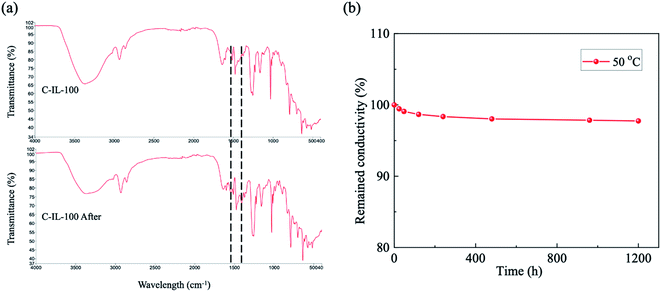 | ||
| Fig. 6 (a) The FT-IR spectra of the C-IL-100 AEM before and after treatment with 1 M KOH at 50 °C for 1200 h. and (b) Remaining conductivity of the C-IL-100 AEM during the stability test. | ||
3.6 Alkaline water electrolysis performance
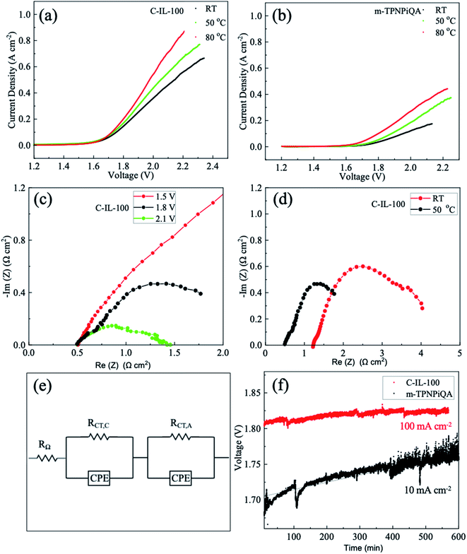
The performance of AEMWEs based on C-IL-100 and m-TPNPiQA membranes was investigated. Because C-IL-100 AEM has the best overall performance (mechanical properties, OH− conductivity and alkaline stability) it was sued for comparison against m-TPNPiQA. Fig. 7a and b show the linear sweep voltammogram of the AEMWE at RT, 50 °C and 80 °C with 1 M KOH fed into both the anode and cathode. Electrochemical polarization is dominant in the non-linear region (low current region), while ohmic polarization is dominant in the linear region (high current region).15 A tremendous improvement in performance was observed for C-IL-100 AEMs compared to m-TPNPiQA. As shown in Table S2,† the current density of the C-IL-100-based AEMWE was 0.55 A cm−2 at 2.0 V while that of the m-TPNPiQA was 0.25 A cm−2 under the same testing condition at 80 °C, established by the high ionic conductivity of the C-IL-100 membrane. In addition, the current density of the C-IL-100 AEM increases with temperature (from 0.31 A cm−2 at RT to 0.55 A cm−2 at a voltage of 2 V and 80 °C), which is comparable with the literature.54–56 Table S3† shows the performance comparison of alkaline water electrolysis based on various AEMs.57–60 The current density of the cell based on C-IL-100 is higher than that of many reported results at a voltage of about 2 V, indicating that C-IL-100 has promising potential for this application.The Nyquist plots of the C-IL-100-based AEMWE were obtained using EIS to explain the influence of voltage and temperature on cell resistance (ohmic resistance (RΩ), charge-transfer resistance (RCT), and mass transport resistance), as illustrated in Fig. 7c and d. By increasing the cell voltage from 1.5 V to 2.1 V, the production rate of hydrogen increased combined with a decline in RCT. The ohmic resistance, RΩ, remained almost unchanged at 2.1 V (0.51 Ω cm2), 1.8 V (0.49 Ω cm2), and 1.5 V (0.47 Ω cm2). The impedance data of the m-TPNPiQA-based AEMWE at 50 °C is shown in Fig. S7.† The RΩ of the m-TPNPiQA-based cell is 4.0 Ω cm2 which is higher than that of the C-IL-100-based cell. This may be one of the reasons that C-IL-100 demonstrated better electrolysis performance than m-TPNPiQA. The crosslinked C-IL-x AEMs have higher molecular weight and better mechanical properties than m-TPNPiQA. The molecular weight difference between m-TPNPiQA and the crosslinked C-IL-100 membrane is also responsible for the electrolysis performance difference since AEMs with low molecular weight detrimentally affect the interface between the membrane and electrode during MEA fabrication.61 As the hydroxide conductivity of the C-IL-100 membrane increased with increasing temperature (from RT to 50 °C), the RΩ decreased from 1.20 Ω cm2 to 0.49 Ω cm2 and the RCT decreased from 3.82 Ω cm2 to 1.30 Ω cm2 (Fig. 7d).
A long-term durability test using a C-IL-100-based AEMWE was performed at a current density of 100 mA cm−2 at 50 °C. As a comparison, an m-TPNPiQA-based AEMWE was operated at a lower current density of 10 mA cm−2, because of its poorer overall performance. As shown in Fig. 7f, an obvious increase in cell voltage over time was observed for the m-TPNPiQA-based AEMWE while only a slight increase was observed for the C-IL-100-based AEMWE, despite the higher current density. The voltage of the C-IL-100-based AEMWE remained almost constant at around 1.81 V during the stability test (500 min). Evidently, there is still room for improvement of the performance of AEMWEs, by optimizing the MEA fabrication methods and operating conditions, and developing highly efficient catalysts and new cell configurations.
4. Conclusion
In summary, we present the preparation and characterization of multi-cation crosslinked C-IL-x membranes and investigated their potential for alkaline water electrolysis. The combination of flexible and densely functionalized crosslinkers is effective to achieve AEMs with good flexibility and mechanical properties. In addition, the crosslinked C-IL-x membranes formed distinct hydrophilic/hydrophobic phase separated structures as confirmed by SAXS and AFM. Compared to non-crosslinked m-TPNPiQA membranes, a significant improvement in ionic conductivity was observed for the multi-cation crosslinked C-IL-100 AEM (94.6 mS cm−1 at 80 °C). The C-IL-x membranes also limit water swelling of the AEMs compared to the non-crosslinked m-TPNPiQA. Besides, C-IL-x have better alkaline stability, electrochemical performance and stability than the m-TPNPiQA membrane. These improvements indicate that multi-cation crosslinked C-IL-x AEMs are potential candidates for AEMWE applications.Author contributions
Xiuqin Wang: conceptualization, methodology, validation, formal analysis, investigation, resources, data curation, writing – original draft. Rob G. H. Lammertink: writing – review and editing, supervision.Conflicts of interest
The authors declare the following financial interests/personal relationships which may be considered as potential competing interests: there are no conflicts to declare.Acknowledgements
The China Scholarship Council (CSC) is gratefully acknowledged. This work is also a part of the Vici project STW 016.160.312 which is financed by the Netherlands Organization for Scientific Research (NWO).References
- C. Li and J.-B. Baek, Nano Energy, 2021, 87, 106162 CrossRef CAS.
- S. Shiva Kumar and V. Himabindu, Mater. Sci. Energy Technol., 2019, 2, 442–454 Search PubMed.
- O. Schmidt, A. Gambhir, I. Staffell, A. Hawkes, J. Nelson and S. Few, Int. J. Hydrogen Energy, 2017, 42, 30470–30492 CrossRef CAS.
- P. Hadikhani, S. M. H. Hashemi, S. A. Schenk and D. Psaltis, Sustainable Energy Fuels, 2021, 5, 2419–2432 RSC.
- K. E. Ayers, E. B. Anderson, C. Capuano, B. Carter, L. Dalton, G. Hanlon, J. Manco and M. Niedzwiecki, ECS Trans., 2010, 33, 3–15 CrossRef CAS.
- A. Z. Al Munsur, B.-H. Goo, Y. Kim, O. J. Kwon, S. Y. Paek, S. Y. Lee, H.-J. Kim and T.-H. Kim, ACS Appl. Mater. Interfaces, 2021, 13, 28188–28200 CrossRef CAS PubMed.
- N. Ul Hassan, M. Mandal, G. Huang, H. A. Firouzjaie, P. A. Kohl and W. E. Mustain, Adv. Energy Mater., 2020, 10, 2001986 CrossRef CAS.
- R. Abbasi, B. P. Setzler, S. Lin, J. Wang, Y. Zhao, H. Xu, B. Pivovar, B. Tian, X. Chen, G. Wu and Y. Yan, Adv. Mater., 2019, 31, 1805876 CrossRef PubMed.
- D. Henkensmeier, M. Najibah, C. Harms, J. Žitka, J. Hnát and K. Bouzek, J. Electrochem. Energy Convers. Storage, 2020, 18, 024001 CrossRef.
- G. A. Lindquist, Q. Xu, S. Z. Oener and S. W. Boettcher, Joule, 2020, 4, 2549–2561 CrossRef CAS.
- J. H. Oh, G. H. Han, H. Kim, H. W. Jang, H. S. Park, S. Y. Kim and S. H. Ahn, Chem. Eng. J., 2021, 420, 127696 CrossRef CAS.
- D. Li, A. R. Motz, C. Bae, C. Fujimoto, G. Yang, F.-Y. Zhang, K. E. Ayers and Y. S. Kim, Energy Environ. Sci., 2021, 14, 3393–3419 RSC.
- K. Zhang, M. B. McDonald, I. E. A. Genina and P. T. Hammond, Chem. Mater., 2018, 30, 6420–6430 CrossRef CAS.
- E. J. Park, C. B. Capuano, K. E. Ayers and C. Bae, J. Power Sources, 2018, 375, 367–372 CrossRef CAS.
- X. Yan, X. Yang, X. Su, L. Gao, J. Zhao, L. Hu, M. Di, T. Li, X. Ruan and G. He, J. Power Sources, 2020, 480, 228805 CrossRef CAS.
- W. E. Mustain, M. Chatenet, M. Page and Y. S. Kim, Energy Environ. Sci., 2020, 13, 2805–2838 RSC.
- P. Overton, W. Li, X. Cao and S. Holdcroft, Macromolecules, 2020, 53, 10548–10560 CrossRef CAS.
- C. Hu, X. Deng, X. Dong, Y. Hong, Q. Zhang and Q. Liu, J. Membr. Sci., 2021, 619, 118806 CrossRef CAS.
- C. Hu, Q. Zhang, H. Wu, X. Deng, Q. Yang, P. Liu, Y. Hong, A. Zhu and Q. Liu, J. Membr. Sci., 2020, 595, 117521 CrossRef.
- Y. S. Kim, ACS Appl. Polym. Mater., 2021, 3, 1250–1270 CrossRef CAS.
- L. Zhu, J. Pan, Y. Wang, J. Han, L. Zhuang and M. A. Hickner, Macromolecules, 2016, 49, 815–824 CrossRef CAS.
- D. W. Shin, M. D. Guiver and Y. M. Lee, Chem. Rev., 2017, 117, 4759–4805 CrossRef CAS PubMed.
- C. Lin, W. Cheng, X. Miao, X. Shen and L. Ling, J. Colloid Interface Sci., 2022, 608, 1247–1256 CrossRef CAS PubMed.
- S. Zhang, X. Zhu and C. Jin, J. Mater. Chem. A, 2019, 7, 6883–6893 RSC.
- J. R. Varcoe, P. Atanassov, D. R. Dekel, A. M. Herring, M. A. Hickner, P. A. Kohl, A. R. Kucernak, W. E. Mustain, K. Nijmeijer and K. Scott, Energy Environ. Sci., 2014, 7, 3135–3191 RSC.
- W. Ma, C. Zhao, J. Yang, J. Ni, S. Wang, N. Zhang, H. Lin, J. Wang, G. Zhang, Q. Li and H. Na, Energy Environ. Sci., 2012, 5, 7617–7625 RSC.
- T. Ko, K. Kim, B.-K. Jung, S.-H. Cha, S.-K. Kim and J.-C. Lee, Macromolecules, 2015, 48, 1104–1114 CrossRef CAS.
- C. X. Lin, Y. Z. Zhuo, E. N. Hu, Q. G. Zhang, A. M. Zhu and Q. L. Liu, J. Membr. Sci., 2017, 539, 24–33 CrossRef CAS.
- N. Chen, C. Lu, Y. Li, C. Long and H. Zhu, J. Membr. Sci., 2019, 572, 246–254 CrossRef CAS.
- C. G. Arges and V. Ramani, Proc. Natl. Acad. Sci., 2013, 110, 2490–2495 CrossRef CAS PubMed.
- Z. Yang, J. Ran, B. Wu, L. Wu and T. Xu, Curr. Opin. Chem. Eng., 2016, 12, 22–30 CrossRef.
- Z. Tao, C. Wang, X. Zhao, J. Li and M. D. Guiver, Adv. Mater. Technol., 2021, 6, 2001220 CrossRef CAS.
- N. Chen, Y. Jin, H. Liu, C. Hu, B. Wu, S. Xu, H. Li, J. Fan and Y. M. Lee, Angew. Chem., Int. Ed., 2021, 133, 19421–19429 CrossRef.
- X. Wang, C. Lin, Y. Gao and R. G. H. Lammertink, J. Membr. Sci., 2021, 635, 119525 CrossRef CAS.
- W.-H. Lee, E. J. Park, J. Han, D. W. Shin, Y. S. Kim and C. Bae, ACS Macro Lett., 2017, 6, 566–570 CrossRef CAS.
- X. Hu, Y. Huang, L. Liu, Q. Ju, X. Zhou, X. Qiao, Z. Zheng and N. Li, J. Membr. Sci., 2021, 621, 118964 CrossRef CAS.
- D. Chen and M. A. Hickner, Macromolecules, 2013, 46, 9270–9278 CrossRef CAS.
- S. Sung, J. E. Chae, K. Min, H.-J. Kim, S. Y. Nam and T.-H. Kim, J. Mater. Chem. A, 2021, 9, 1062–1079 RSC.
- L. Li, Q. Yang, X. L. Gao, H. Y. Wu, Q. G. Zhang, A. M. Zhu and Q. L. Liu, J. Mater. Chem. A, 2018, 6, 24831–24840 RSC.
- A. M. Park, R. J. Wycisk, X. Ren, F. E. Turley and P. N. Pintauro, J. Mater. Chem. A, 2016, 4, 132–141 RSC.
- C. Hu, Q. Zhang, C. Lin, Z. Lin, L. Li, F. Soyekwo, A. Zhu and Q. Liu, J. Mater. Chem. A, 2018, 6, 13302–13311 RSC.
- D. Guo, C. X. Lin, H. E. Ning, L. Shi, F. Soyekwo, Q. G. Zhang, A. M. Zhu and Q. L. Liu, J. Membr. Sci., 2017, 541, 214–223 CrossRef CAS.
- M. Behl, M. Balk, U. Mansfeld and A. Lendlein, Macromol. Mater. Eng., 2021, 306, 2000672 CrossRef CAS.
- N. Chen, C. Lu, Y. Li, C. Long, Z. Li and H. Zhu, J. Membr. Sci., 2019, 588, 117120 CrossRef CAS.
- X. L. Gao, L. X. Sun, H. Y. Wu, Z. Y. Zhu, N. Xiao, J. H. Chen, Q. Yang, Q. G. Zhang, A. M. Zhu and Q. L. Liu, J. Mater. Chem. A, 2020, 8, 13065–13076 RSC.
- J. Si, S. Lu, X. Xu, S. Peng, R. Xiu and Y. Xiang, ChemSusChem, 2014, 7, 3389–3395 CrossRef CAS PubMed.
- G. A. Giffin, S. Lavina, G. Pace and V. Di Noto, J. Phys. Chem. C, 2012, 116, 23965–23973 CrossRef CAS.
- M. Liu, X. Hu, B. Hu, L. Liu and N. Li, J. Membr. Sci., 2022, 642, 119966 CrossRef CAS.
- H. J. Park, S. Y. Lee, T. K. Lee, H.-J. Kim and Y. M. Lee, J. Membr. Sci., 2020, 611, 118355 CrossRef CAS.
- J. S. Olsson, T. H. Pham and P. Jannasch, J. Membr. Sci., 2019, 578, 183–195 CrossRef CAS.
- N. Chen, C. Hu, H. H. Wang, S. P. Kim, H. M. Kim, W. H. Lee, J. Y. Bae, J. H. Park and Y. M. Lee, Angew. Chem., Int. Ed., 2021, 60, 7710–7718 CrossRef CAS PubMed.
- X. Du, H. Zhang, Y. Yuan and Z. Wang, J. Power Sources, 2021, 487, 229429 CrossRef CAS.
- T. H. Pham, J. S. Olsson and P. Jannasch, J. Mater. Chem. A, 2018, 6, 16537–16547 RSC.
- L. Lee and D. Kim, J. Mater. Chem. A, 2021, 9, 5485–5496 RSC.
- Y.-C. Cao, X. Wu and K. Scott, Int. J. Hydrogen Energy, 2012, 37, 9524–9528 CrossRef CAS.
- X. Wu and K. Scott, J. Power Sources, 2012, 214, 124–129 CrossRef CAS.
- Z. Liu, S. D. Sajjad, Y. Gao, H. Yang, J. J. Kaczur and R. I. Masel, Int. J. Hydrogen Energy, 2017, 42, 29661–29665 CrossRef CAS.
- J. J. Kaczur, H. Yang, Z. Liu, S. D. Sajjad and R. I. Masel, Front. Chem., 2018, 6, 263 CrossRef PubMed.
- M. Najibah, E. Tsoy, H. Khalid, Y. Chen, Q. Li, C. Bae, J. Hnát, M. Plevová, K. Bouzek, J. H. Jang, H. S. Park and D. Henkensmeier, J. Membr. Sci., 2021, 640, 119832 CrossRef CAS.
- H. Li, M. R. Kraglund, A. K. Reumert, X. Ren, D. Aili and J. Yang, J. Mater. Chem. A, 2019, 7, 17914–17922 RSC.
- C. Fujimoto, D.-S. Kim, M. Hibbs, D. Wrobleski and Y. S. Kim, J. Membr. Sci., 2012, 423–424, 438–449 CrossRef CAS.
Footnote |
| † Electronic supplementary information (ESI) available. See DOI: 10.1039/d1ta10820d |
| This journal is © The Royal Society of Chemistry 2022 |

