
 Open Access Article
 This Open Access Article is licensed under a
 Creative Commons Attribution 3.0 Unported Licence
Local strain-induced energy storage as driving force for autogenous scratch closure†
V.
Montano
 a,
M. W.
Urban
b,
S.
van der Zwaag
a and
S. J.
Garcia
*a
a,
M. W.
Urban
b,
S.
van der Zwaag
a and
S. J.
Garcia
*a
aNovel Aerospace Materials Group, Faculty of Aerospace Engineering, Delft University of Technology, Kluyverweg 1, Delft, 2629 HS, The Netherlands. E-mail: s.j.garciaespallargas@tudelft.nl
bDepartment of Materials Science and Engineering, Clemson University, Clemson, SC 29634, USA
First published on 7th February 2022
Abstract
Autonomous through-thickness scratch repair (healing) in coatings requires scratch closure and interfacial molecular sealing. Although qualitative aspects of the first stage of self-healing have been addressed, quantitative description enabling the control over the healing process need further understanding. In this work the polymer-architecture-dependent stored entropic energy during deformation is quantified using the rubber elasticity theory and correlated to the scratch closure degree experimentally observed in microscopic measurements. Using well-defined thermoplastic healing polyurethanes with variable soft phase fraction contents these studies show that pressure-free damage closure of scratches maintaining mechanical integrity during healing is governed by the capability of the polymer to store entropic energy during damage. The storage (and release) of energy is controlled by varying the damage and healing temperatures in relation to the specific viscoelastic length transition (TVLT) and the glass transition temperature (Tg). Damage closure increases linearly with the entropy release and is controlled by two parameters of the network, the junction density and damping factor. If mechanical damage does not lead to storage of mechanical energy healing does not occur.
1. Introduction
Environmental concerns related to material overconsumption and the ineffective life cycle of commodity polymers are valuable drivers for the development of alternative and more sustainable solutions to current materials and design rules.1–4 Among the various strategies explored by polymer scientists, the development of self-healing polymers is one of the promising routes to extend the life-time of polymers.5–9 Autonomous self-healing polymers rely on the incorporation of a fraction of reversible bonds that allow the temporary de-construction of the network, while permanent crosslinks, main chain entanglements or microphase separation ensure mechanical robustness and network integrity.10 In recent years the inclusion of multiple yet low energetic physical interactions including H-bonding and van der Waals (vdW) interactions have offered as a clear strategy for the synthesis of self-healing commodity polymers requiring only minimal chemical modifications, i.e. retaining their commodity character.11–14In order to obtain fully autogenous healing in polymers and coatings, strategies to ensure local polymer displacement are to be implemented in healing polymers. One pathway is the use of shape memory behaviour to assist the first stage of the healing process (i.e. damage closure). This combination of self-healing and shape memory effects is exploited in the so-called shape memory assisted self-healing (SMASH). In these systems the displacement resulting from shape memory effect leads to damage closure while the dynamic nature of reversible molecular moieties contributes to the necessary interfacial diffusion and bond reformation to ensure sealing. Although some works have shown the effect of implementing this strategy,15–18 the quantitative aspects of entropy release and scratch closure displacement still remain unaddressed; a critical aspect for the future design and optimisation of self-healing polymers with market potential.
Recent studies introduced a methodology that allows quantifying the stored and released energy during deformation and recovery in shape memory polymers (SMP). SMPs exhibit so-called viscoelastic length transitions (VLTs) near the glass transition (Tg):12,19 macroscopic changes in length (extension and retraction) due to release of stored energy occurring at Tg. These processes and their energetic contribution to the shape recovery can be identified and quantified when deforming and temperature cycling in dynamical mechanical analysis (DMTA) tests. Mechanistically, the model uses the viscous component of the network which is responsible for the length extension at the transition temperature while the subsequently observed retraction is an entropy-driven process driven by the storage and release of free conformational states taking place during and after the transition temperature, respectively. By quantifying the entropic storage (ΔSS) and entropic release (ΔSR) at VLT a relative measurement of the shape memory effect (SME) can be obtained. Previous studies have shown that, for a given set of DMA measurement conditions (e.g. deformation amplitude, oscillation frequency and heating rate) ΔSS increases linearly with the junction density (νj) and the maximum value of the damping factor (tan![[thin space (1/6-em)]](https://www.rsc.org/images/entities/char_2009.gif) δmax).20 To further expand the scope of these studies higher (or more controlled) levels of stored and released entropy facilitating damage closure can be explored to demonstrate the potential of the approach more quantitatively.
δmax).20 To further expand the scope of these studies higher (or more controlled) levels of stored and released entropy facilitating damage closure can be explored to demonstrate the potential of the approach more quantitatively.
The current study tests the hypothesis that different levels of released entropy during the shape memory transition can be accessed by controlling the damage and healing temperatures, which can be quantitatively assessed in terms of the released entropy that contributes to the scratch closure. Using this approach empirical relations between released entropy, junction density, and scratch closure displacement for thermoplastic healing polyurethanes with known and variable healing kinetics can be developed. Since the closure mechanism is based solely on the viscoelastic nature of the material, this concept can be extended to other self-healing and/or shape memory polymers.
2. Experimental section
2.1 Synthesis of the TPU and coating preparation
Five segmented polyurethanes were synthesized by single shot technique reacting CroHeal™ 1000, IPDI and BDO. The compositions cover a broad range theoretical soft phase fraction (χSF) defined as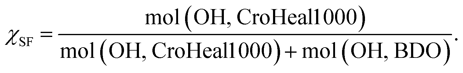 Below the synthesis of the PU with χSF = 0.42 is reported in details. Analogous procedures were followed for the other polymers in this study. Details on their synthesis are reported in the ESI at Table S1.†
CroHeal™ 1000 was heated for 1 hour at 60 °C to reduce the intrinsic viscosity of the monomer. Subsequently 6.0 grams (4.86 mmol) of CroHeal™ 1000 were transferred to a 20 ml polypropylene cup. Butyl acetate solvent (BuAc, 0.6 g, 6.66 mmol) was quickly added to further reduce the intrinsic viscosity. 0.6 g of 1,4-butanediol were then transferred to the cup (BDO, 0.6 g, 6.66 mmol). Subsequently TEGO 270 (0.024 g) and dibutyltin dilaurate (DBDTL, 0.063 g, 0.1 mmol) were added dropwise. Immediately thereafter, isophorone diisocyanates (IPDI, 2.82 g, 12.68 mmol) was injected. The system was stirred vigorously using a mechanical agitator and the reaction proceeded for 15 seconds at room temperature. The mixture was then applied on a acetone cleaned carbon automotive steel plate (Q-panel) using a coating bar with a wet thickness of 150 μm. The coated panel was dried for 30 minutes at ambient laboratory conditions and subsequently cured for 30 minutes at 60 °C in an air recirculating furnace. The polyurethane coatings were then equilibrated for 1 week at ambient laboratory conditions prior to scratch and corrosion resistance testing. For bulk characterization of the at the end of the synthesis the polymer was transferred to a 4 × 4 PTFE mold, then equilibrated for 30 minutes in ambient condition and subsequently cured 30 minutes at 60 °C. The bulk polymers were equilibrated for 1 week at ambient condition before testing using TGA, DSC and DMA analysis.
All the TPUs were synthesized following an analogous procedure but varying the monomer feed ratio. Details are reported in Table S1.†
2.2 Dynamical mechanical analysis (DMA)
DMA analysis was performed on a Q800 DMA (TA instrument) in strain control mode. The initial gauge length was set to 10.0 ± 0.1 mm, strain amplitude = 10 μm, force track = 125% and frequency set a 1 Hz, with heating rate = 2 °C min−1 and frequency = 10 Hz. The samples have rectangular geometry, with average width = 2.0 ± 0.05 mm and average thickness = 0.5 ± 0.1 mm. The test chamber was cooled to the starting temperature (−50 °C) without applying any force on the polymer specimen (floating condition) to ensure that any pre-deformation was applied before the start of the experiment. DMA VLT values were calculated as described by Hornat et al.,19 and are explained in details in the main text. Every composition was tested three times. The VLT values used in this study are obtained as the algebraic mean of the set of DMA tests.2.3 Damage and healing conditions
In order to obtain comparable initial scratch damage and exclude any effect related to the network dissipations on damage mechanics, the TPUs were damaged at the temperature corresponding to a fixed strain of ε = 0.1% (Ti of Fig. 1b), well within the glassy regime. The temperature was controlled by using a Peltier TEC Heating/Cooling Module, in cooling mode, varying the input voltage between 0.1 and 4 V. The damages of 5 mm in length were produced by using a razor blade tip (width ≈ 100 μm) and a fixed axial force (FN = 1.8 N), ensuring the blade tip to reach the metal substrate. The damages were subsequently subjected to isothermal healing at the temperature corresponding to the midpoint and the end point of the strain-temperature VLT retraction (Tmid and Tend-point of Fig. 1b) using a Peltier TEC Heating/Cooling Module, in heating mode, varying the input voltage between 0.5 and 4 V. The damages were healed for 60 seconds in accordance with typical kinetics of the SME in polymers.16,21 The use of such a short healing time excluded any effect of long-range polymer dynamics on scratch closure displacement. The damage/healing protocol is linked to the DMA VLT protocol to access a wide range of theoretical ΔSR which was calculated for every damage/healing condition by using eqn (6). All damaging (Ti) and healing temperatures (Tmid and Tend-point) used and the corresponding ΔSR values are reported in Table S3.† The formulations χSF = 0.71 and χSF = 0.51 were additionally tested at the temperature reported in Table S4.†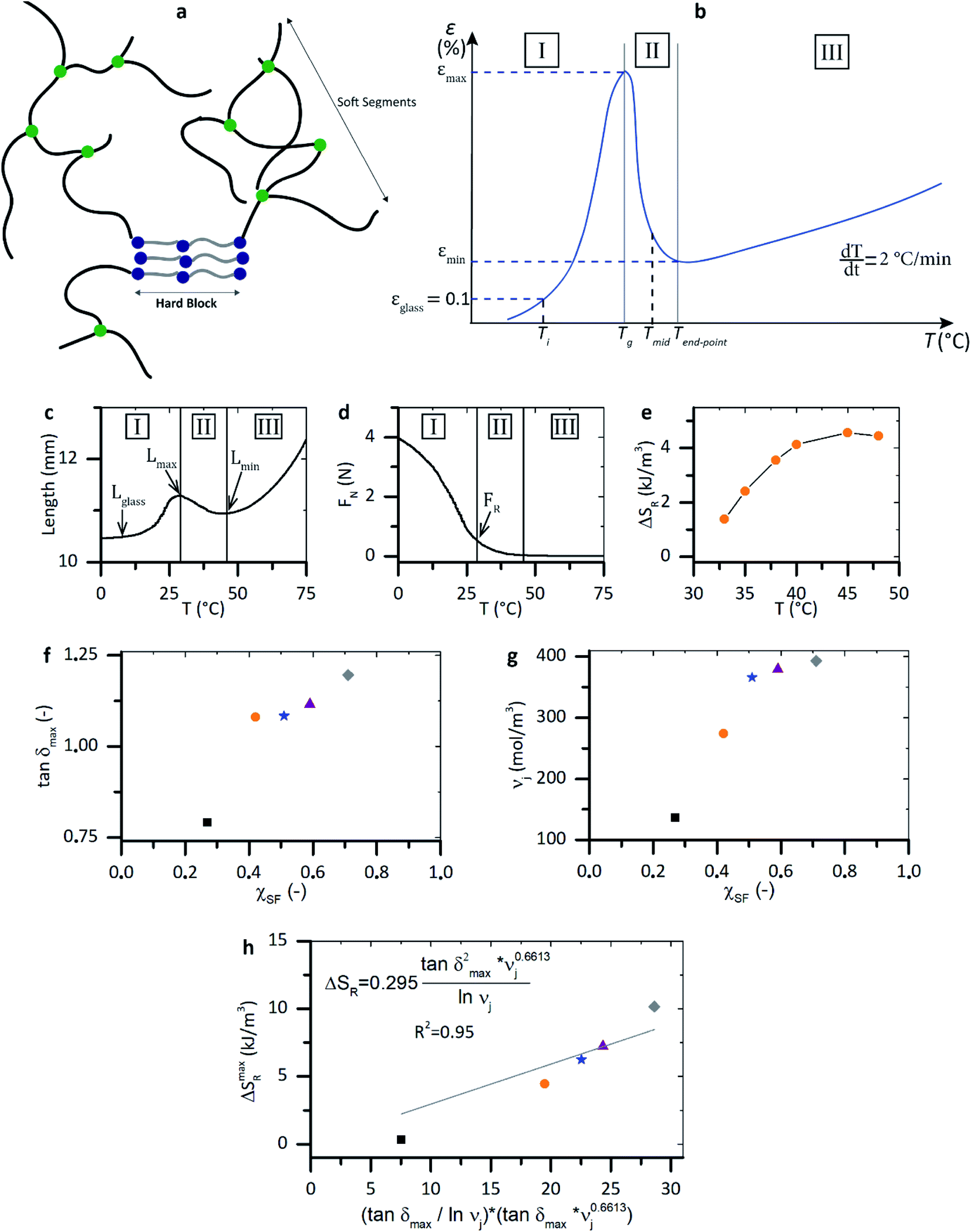 | ||
| Fig. 1 Network morphology and shape memory VLTs results. (a) Schematic representation of TPU phase separated morphology. (b) Schematics of the classical dependence of strain on temperature during VLT transition. Step I: extension due to soft segments unfolding. Step II: retraction due to release of stored conformational entropy. Step III: extension due to hard blocks delayed unfolding. (c and d) Experimental temperature dependence of sample length (sample length) and normal static force (FN) for χSF = 0.42 as obtained by DMA analysis. (e) ΔSR temperature dependence as calculated from eqn (6). Note that ΔSR > 0 only during stage 2 of the VLT transition, in the retraction phase. (f and g) Polymer viscoelasticity (tanδmax) and junction density (νj) dependence on soft phase molar fraction. (h) ΔSmaxR dependence on (tanδmax × νj0.6613) × (tanδmax × lnνj) equivalent to the product of the macroscopic mechanical responses to the VLT transition (σSF at εmax × εmax). | ||
Engrave damages of 5 millimeters in length were produced using a mechanical engraver equipped with AC125-BAL-PRO-0.002 Carbide Profiler for Engraving with a 15 degrees tip (tip width size of 0.002 inches ≈ 50 μm).
2.4 Optical microscopy
High resolution optical micrographs of damaged and healing coatings were acquired using a Keyence VHX-2000 digital microscope with optical magnification in the range 20× to 1000×.3. Results and discussion
3.1 Theoretical background: stored and released entropy extrapolation from experimental data
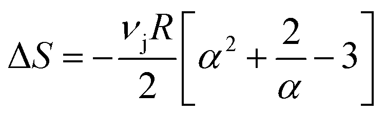
To set the stage, we illustrate a generic network morphology of the thermoplastic polyurethanes (TPU) used for this study in Fig. 1a and analyse the classical dependence of the measured strain (ε) on temperature during an extensional dynamical mechanical analysis (Fig. 1b). In this polymer networks, soft segments segmental mobility is responsible for the increase of dissipation at low temperature below Tg, while the hard blocks act as semi-permanent netpoints guaranteeing network integrity upon large strain deformation (when melt occurs). As a result, shape memory viscoelastic length transitions (VLTs) are observed near Tg. The initial length extension until εmax is attributed to decoiling of the soft segments (Step I). The subsequent length retraction down to εmin is attributed to the release of stored entropic energy density (ΔSR) accumulated in the polymer due to the mobility restrictions of the soft segments imposed by soft segment H-bonding and chain entanglements (Step II). The following slow extension (Step III) is attributed to delayed decoiling of hard blocks. Starting from extensional dynamical mechanical analysis, a similar description of network dynamics was attributed to shape memory TPU having an amorphous soft phase.22As derived from thermodynamics and rubber elasticity theory23,24 the decrease in conformational entropy occurring at VLTs20 can be estimated as
 | (1) |
 measurable with the DMA measurements), νj is the junction density (
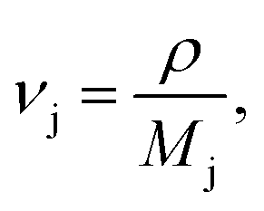 where Mj is the apparent molecular weight between entanglements and is the characteristic design parameter of the network), and R is the universal gas constant. The entropic energy storage generates a retractive force (FR) expressed as
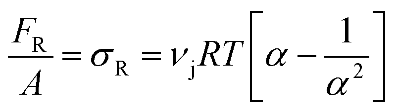 | (2) |
Following the analytical relationships derived through the rubbery elasticity theory, an experimental protocol19,20,25 that consists in the performance of a single DMA experiment, was used to quantify the stored (ΔSS) and released (ΔSR) entropy density at the viscoelastic length of transition. The entropy is stored during the length extension observed during the DMA analysis (Step I of Fig. 1b). As derived from classical thermodynamics:
| ΔSS = −TεISεI + TiSi | (3) |
By combining eqn (1) and (3) it follows that:
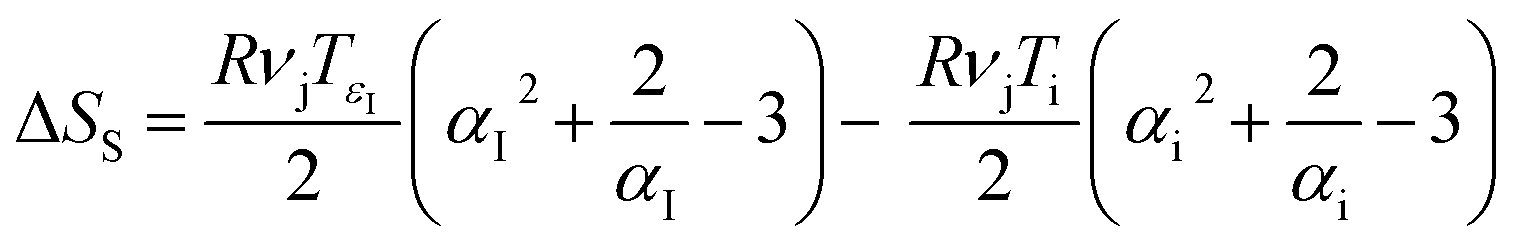 | (4) |
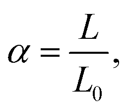
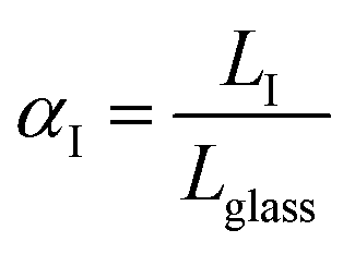 is the ratio between the length of the sample tested in DMA at any point during extension (LI) and its length well within the glassy regime so that
  The stored entropy reaches a maximum when LI = Lmax, in correspondence of the maximum elongation (εmax in Fig. 1b):
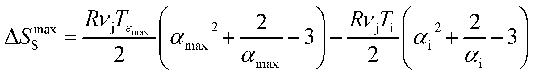 | (5) |
The stored entropy is then released during the length retraction stage induced by the elastic behaviour of H-bonds and entanglements (Step II of Fig. 1b):
| ΔSR = −TεminSεmin + TεmaxSεmax | (6) |
By combining eqn (1) and (6) it is derived:
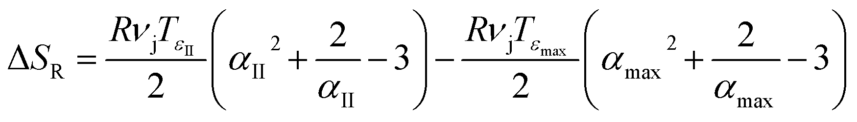 | (7) |
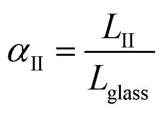 is the ratio between the length of the DMA tested sample at any point in the retraction stage (LII), between Lglass and Lmax. The released entropy reaches its maximum when LII = Lmin, in correspondence to the elongation minimum (εmin of Fig. 1b):
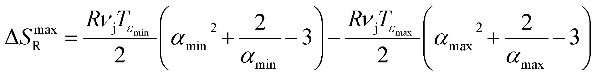 | (8) |
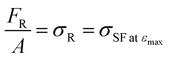 corresponds to the stress measured from the DMA loading cell at the maximum elongation (so it is an observable), we can estimate the junction density νj through eqn (2) as:
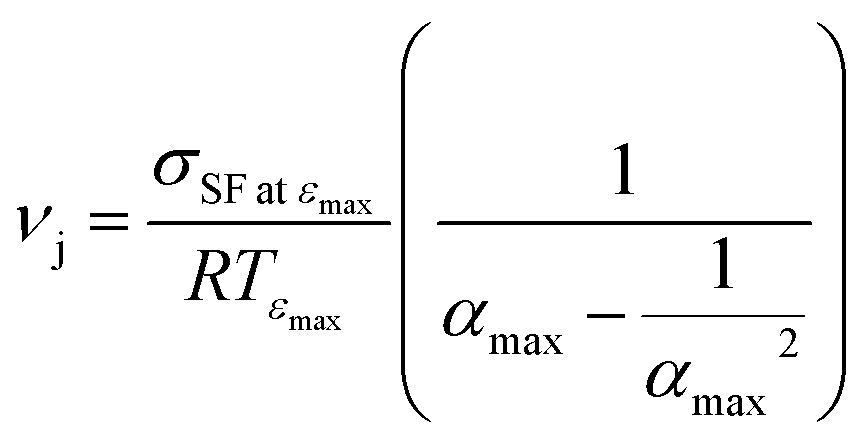 | (9) |
To quantify the effect of polymer architecture on all VLTs-related parameters (ΔS, νj, σR) a set of healing and non-healing TPUs were synthetized by varying the nominal soft phase fraction 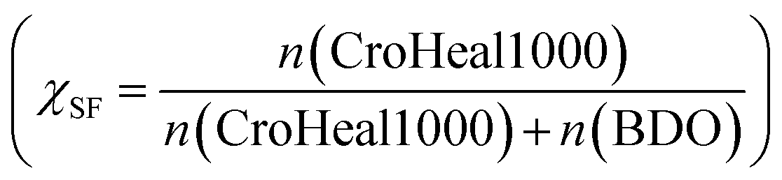 as reported elsewhere26 and tested by DMA. These self-healing systems were showed to effectively restore barrier property upon healing, through a series of accelerated electrochemical test performed in marine water conditions.26
Fig. 1c and d show the temperature dependence of sample length and normal force for a specific TPU (χSF = 0.41) as obtained in a DMA test. Lglass is selected at a deformation of 0.1%, as a point in which none/little deformation has occurred. Lmax and Lmin are respectively the length at the maximum of extension and retraction. FR corresponds to the normal (static) force measured from the DMA loading cell at the moment of the maximum extension, when sample retraction starts. Using these experimental values, ΔSR is calculated at different temperatures within the retraction stage by using eqn (7) and plotted in Fig. 1e.
Hornat et al.,20 using the careful analysis of the relation between the DMA experimental values (εmax and σSF at εmax) and two characteristic network parameters (tanδmax, which is indicative of network viscoelasticity and νj which represents network connectivity) showed for shape memory polymers that ΔS can be correlated to tanδmax and νj. In particular this is empirically verified that ΔS ∝ σSF at εmax × εmax = (tanδmax × νj0.6613) × (tanδmax/lnνj) and follows a linear relationship. The relationship was verified for multiple polymer systems. tanδmax and νj can be derived from the DMA analysis and are controlled through the network chemical modifications explored in this work. Fig. 1f and g show the effect that an increase in polyurethane soft phase fraction exerts on tanδmax and νj. The first polymer extension was attributed to the unfolding of the polyurethane soft phase, polymers designed with higher soft phase fraction (χSF) show therefore higher viscous dissipation (higher tanδmax) at the VLTs (Fig. 1f) because a larger network fraction is able to dissipate the mechanical load. Moreover, H-bonding and main chain entanglements in the soft phase act as molecular switches for the shape memory viscoelastic transition (the VLT transition). In agreement with this, an increase in soft phase molar fraction (χSF) coincides with an increase of junction density νj (Fig. 1g). The junction density tends to plateau for χSF > 0.5, suggesting that a saturation level in hydrogen bonding and entanglements is reached in the soft phase.
As illustrated in Fig. 1h, when connecting ΔSmaxR to the network characteristic parameters a linear relationship is obtained:
 | (10) |
TPUs with high tanδmax and νj undergo a more effective limitation of conformational states during VLTs, determining an increase of maximum released entropy ΔSmaxR. This equation can be used to directly obtain the values of ΔSmaxR from δmax and νj.
Details regarding synthesis, characterisation and analysis methods are provided in the ESI.† All the VLT parameters (ΔSmaxS, ΔSmaxR, νj, σSF at εmax, εmax) are listed in Table S2.†
To examine the relationship between the released entropy calculated through the VLTs analyses and the macroscopic scratch closure behaviour we introduce a testing protocol based on controlled temperature scratching and healing combined with optical microscopy analysis of 100 μm thick TPU polymers applied on steel plates. The damage and healing temperatures were established based on the strain–temperature relationships observed in DMA measurements. The testing protocol of these tests is fully provided in the ESI.†
3.2 Relation of closure to released entropy and polymer architecture
Once established the theoretical and experimental framework, the research proceeded on establishing a relation between degree of scratch closure, released entropy and polymer architecture.Fig. 2a–c presents optical micrographs of the scratch recovery of three TPUs with different soft phase molar fractions (χSF) at two healing times, with corresponding theoretical values of ΔSR and the specific healing temperatures used. The damage recovery (i.e. crack closure) is attributed to an effective entropic release (ΔΔSR). It should be noted that all studied polymers complete the fast entropy driven closure of the performed scratches within the first minute of isothermal heating at healing temperature. Interestingly, the higher temperature required to trigger the closure of the lowest χSF = 0.27 (Thealing = 80 °C, snapshots AI and AII) does not lead to a larger closure displacement than that closure observed for the highest soft fraction system χSF = 0.71 taking place at a considerably lower temperature (Thealing = 35 °C, snapshots CI and CII).
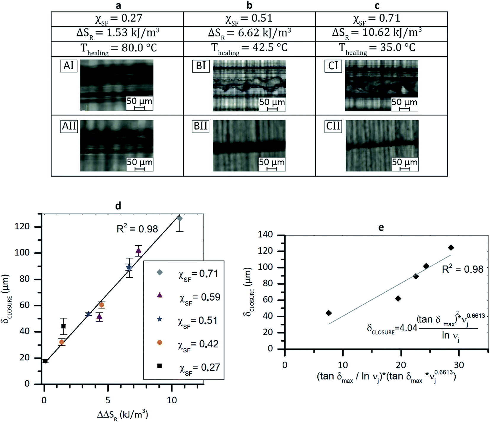 | ||
| Fig. 2 Closure displacement relation to released entropy and polymer design. (a–c) Optical micrographs of damage TPU polymers. χSF = 0.27 (ΔSR = 1.53 kJ m−3) was healed at 80 °C (AI-AII). χSF = 0.51 (ΔSR = 6.62 kJ m−3) was healed at 42.5 °C (BI-BII). χSF = 0.71 (ΔSR = 10.62 kJ m−3) was healed at 35 °C (CI–CII). (d) δCLOSURE dependence on ΔΔSR. Note that data points are well fitted by a linear spline. (e) δCLOSURE dependence on (tanδmax × νj0.6613) × (tanδmax/lnνj) equivalent to the product (σSF at εmax × εmax). Note that data points are well fit by a linear spline. | ||
In order to quantitatively relate scratch gap closure to entropy release in the VTL, the scratch closure displacement (δCLOSURE) was estimated as
| δCLOSURE = Wi − Wf | (11) |
As illustrated in Fig. 2d the δCLOSURE increases monotonically with ΔΔSR, independently of the soft-hard ratio used. The data points are well fitted by a common linear dependence (for which the scientific justification yet has to be provided):
| δCLOSURE = 15.79 + 10.68(ΔΔSR) | (12) |
Interestingly, both experimental data and empirical predictions based on eqn (12) indicate δCLOSURE ≠ 0 at a virtual ΔΔSR = 0. This result is explained by two fundamental assumptions used in our calculations that can be regarded as approximations. On the one hand, it is assumed that all the energy stored during the mechanical deformation is used to limit the polymer conformational states (ΔSS = ΔΔSS and ΔSR = ΔΔSR), i.e. local compression. In reality, during the damage the majority of the energy involved in the damage is stored as entropic energy density leading to conformational restrictions, but part of it will be lost in chain scission with no contribution to the damage closure, and part of it will be elastically stored by the network (chemical bonds bending and contraction), with just partial (marginal) macroscopic closure upon release at VLT onset. On the other hand, it is approximated that all the stored energy is released in the form of damage closure with no energy loss in other processes such as that involved to overcome friction.
To establish a relation between scratch closure displacement and network characteristic design parameters, δCLOSURE can be plot against the relationship (tanδmax × νj0.6613) × (tanδmax/lnνj) as shown in Fig. 2e. This leads to a second linear relationship similar to eqn (10):
 | (13) |
The five TPUs used to obtain the data points showed in Fig. 2d were examined by healing every polymer at two temperatures corresponding to the midpoint and the end point of the strain-temperature VLT observed in DMA. The polymers and scratching conditions made sure a wide range of released entropy (0.1 <ΔΔSR < 11 kJ m−3) was covered. An equally broad range can be accessed by exploiting the different temperatures of VLT retraction (Tretraction) of a specific system (temperatures in stage II). By analysing the relation between ΔSR at Tretraction for χSF = 0.71 and 0.51, the broad spectrum of released entropy was reconstructed by testing these two systems at five healing conditions marked as data-points in Fig. 3a. The additional healing temperatures and the calculated ΔSR are provided in Table S4.† The scratch-healing results are presented in Fig. 3b and again show a linear dependence of δCLOSURE on ΔΔSR (continuous grey line in Fig. 3b). The spline is in good agreement with the linear relationship derived by bulk straining of all polymers (χSF = 0.71, 0.59, 0.51, 0.42, 0.27) at the Tmid and Tend-point (reported in Fig. 2d) and indicated by the dashed black dashed line in Fig. 3b. The analysis confirms that a (semi-) quantitative prediction of δCLOSURE based on the entropic storage estimated by DMA analysis (ΔSR) is possible.19,20
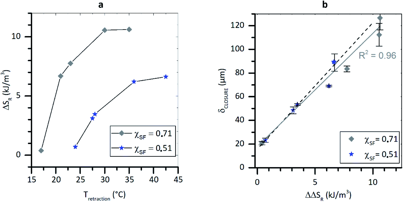 | ||
| Fig. 3 Closure displacement relation to released entropy in wide range of healing temperature for two specific systems (χSF = 0.71 and 0.51). (a) ΔSR dependence on Tretraction. (b) δCLOSURE dependence on ΔSR. | ||
The linear relationship linking δCLOSURE to ΔSR shown above was derived for a specific damage condition that consists of the use of a sharp 100 μm wide razor blade tip. Under this conditions, the material next to the scratch is subjected to the deformation state represented qualitatively in Fig. 4a, in which a large polymer displacement occurs at the damage zone, setting a damage-induced strain region. This deformation determines the local entropic storage responsible of the polymer delayed elasticity upon healing that causes the closure as shown in Fig. 4(AI and II).
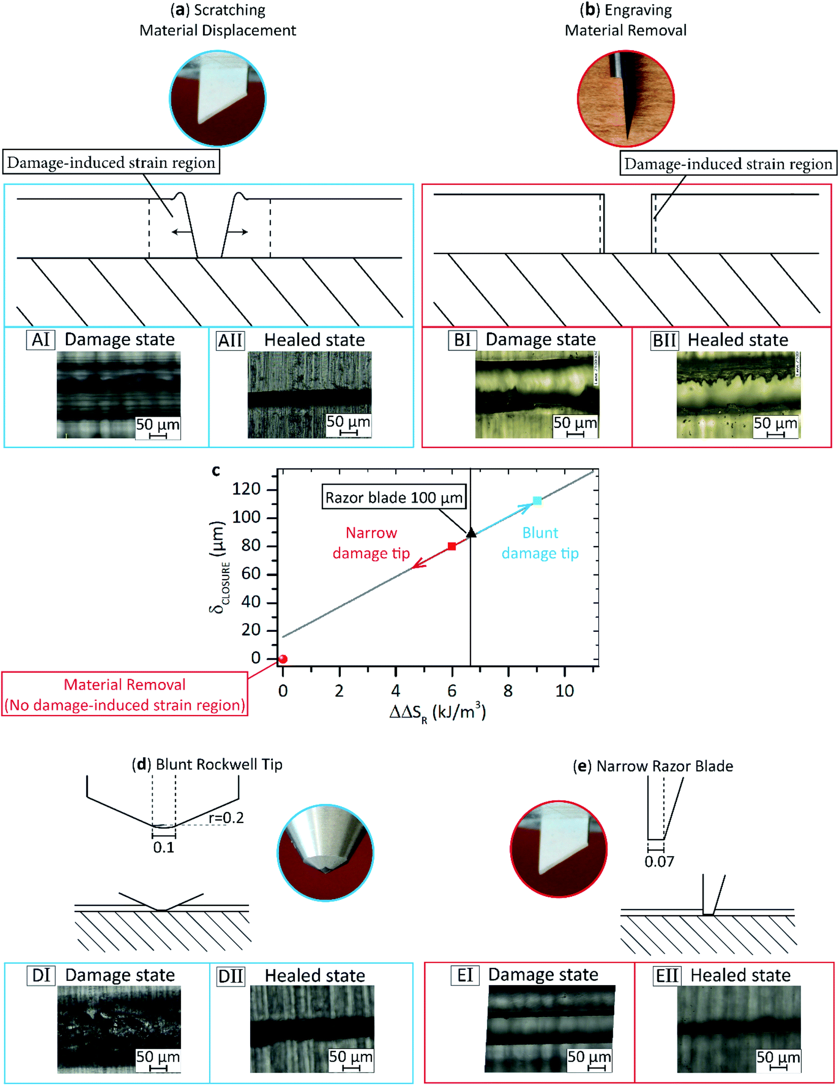 | ||
| Fig. 4 Effect of damage mode on closure displacement. (a) Scratching causes material displacement at the damage zone. A damage-induced strain region is set, enabling efficient entropy storage. Good closure is observed upon healing. (b) Engraving determines material removal. Since the material is removed but not displaced, only a minimal entropic storage is possible at the damage lateral walls. Poor closure is observed upon healing. (c) Quantitative evaluation of the effect of damage mode and the use of a blunt and a narrow indenter. (d and e) Schematic overviews and photographs of the damaging tips used. All the quotes are given in millimetres. (DI, DII, EI, EII) Optical micrographs acquired before and after healing treatment of samples damaged with Rockwell tip (DI–DII) and narrow razor blade (EI–EII). | ||
To demonstrate the necessary role of entropy storage during the damaging event on the autogenous scratch closure we performed an analogous experiment on the same TPU yet using a damaging tip and mode different to the scratching described above. In this test we produced a damage with a rotating carbide tip using a mechanical engraver. The high torque of the metal tip shutters the polymer provoking material removal and a substantially different deformation state compared to the previous case, as represented in Fig. 4b. In this case the material next to the scratch is only minimally strained, and therefore only a small damage-induced strain region next to the scratch is created. Upon imposing the thermal healing treatment, no displacement of the lateral scratch walls is observed and the scratch is still fully open as shown in Fig. 4(BI and BII) and is quantitatively reported in Fig. 4c as red ball symbols. This experiment indicates that despite the theoretical entropy storage of the polymers calculated between damage and healing temperature, is unchanged, the effective entropy storage that determines the entropy driven closure has to be exploited through a damage mode that privileges material displacement over material removal. Entropy storage, and therefore scratch closure, is a visco-elastic strain-induced phenomenon.
3.3 Effect of damage geometry: material displacement vs. material removal
Since the entropy storage is dependent on the presence of a strain profile in proximity of the damage zone, we argue that the use of a blunter or narrower razor blade tip will lead respectively to a higher and lower entropy storage/release, even if the polymer used and the damage/healing temperature conditions are unaltered. A blunter tip induces a broader strain field, while a narrower one yields to a shrinking of the strain field. To confirm the hypothesis the controlled temperature scratching/healing tests were repeated using a conical Rockwell diamond tip (width ≈ 100 μm, curvature radius r ≈ 200 μm) and a razor blade tip, equal to the previous one used but thinned to 70 μm. Schematic overviews of the additional scratching tips used is shown in Fig. 4d. The use of the blunt Rockwell results in a higher initial damage width (WRockwelli ≈ 200 μm) compared to that for the razor blade damage (WRzBi ≈ 130 μm). Upon isothermal healing, the damage provoked by the Rockwell tip displaces to the final scratch width of Wf ≈ 20 μm (δCLOSURE ≈ 110 μm) as derived from the optical micrographs acquired after damage and healing (Fig. 4(DI and DII)). The use of a blunter tip sets a larger strain-induced region that determines a higher entropy storage/release resulting in a higher closure than the sharp tip of 100 μm. A qualitative estimation of the ΔΔSR exploited when using the Rockwell tip is realized by inverting the derived linear relationship linking δCLOSURE to ΔΔSR (eqn (11), reported as grey spline in Fig. 4c). As shown in Fig. 4c (cyan square marker) a value of ΔΔSR ≈ 9.0 kJ m−3 corresponds to the observed closure displacement of 110 μm.When a thin (70 μm) sharp razor blade is used instead of a thicker (100 μm) sharp razor blade, a smaller initial scratch width is set (Wi ≈ 90 μm), and lower closure is observed (δCLOSURE ≈ 80 μm), confirming the hypothesized decrease of the damage-induced strain region (Fig. 4(EI and EII)). However, despite the absolute reduction of δCLOSURE, the scratch is only barely visible. In fact, much lower levels of released entropy are sufficient to fully heal the damage, setting a polymer-specific level of damage closure saturation. By inverting eqn (10) we argue that values of ΔΔSR no higher than ≈ 5.2 kJ m−3 will be sufficient to fully close up a 90 μm wide damage (red square marker in Fig. 4c). The approach is universal provided that the material shows sufficient length extension and successive retraction at the VLT.
4. Conclusions
A linear relation between the amount of released locally stored energy in a scratched thermoplastic healing polymers and the closure of the scratch is determined. In general terms, enhanced closure will be obtained in polymers with a high junction density and combinations of sufficient local deformation during damage and healing temperatures which lead to an optimal release of the stored energy. Specific polymer design could be used to target unique applications with known damage events. Autonomous gap closure, as here explored, is the necessary step to develop autonomous self-healing coatings. However, gap closure must not be confused with healing in coatings which stands for the recovery of functions or properties (such as barrier or mechanics) that require, subsequent to gap closure, interfacial chemical and physical interactions between the two planes once the damage has closed. The current work proposes a critical advance in the design of the next generation of shape memory and self-healing polymer commodities. Although the method and hypothesis here exposed are expected to be generally applied to other polymer systems, more dedicated research is needed to evaluate the effect of thickness and presence of covalent reversible bonds (e.g. Diels–Alder adducts) on the damaged-induced strain field and healing.Conflicts of interest
There are no conflicts to declare.Acknowledgements
The authors acknowledge the financial support of Croda Nederland BV and the Dutch National Organization for Scientific Research, Domain Applied and Engineering Sciences (NWO-TTW) under the grant number 15010. The authors acknowledge Dr Angela Smits and Dr Wouter Vogel (Croda) for helpful discussions and valuable feedback.References
- X. Zhang, M. Fevre, G. O. Jones and R. M. Waymouth, Chem. Rev., 2018, 118, 839–885 CrossRef CAS PubMed.
- M. A. R. Meier, J. O. Metzger and U. S. Schubert, Chem. Soc. Rev., 2007, 36, 1788–1802 RSC.
- B. S. Sumerlin, Science, 2018, 362, 150–151 CrossRef CAS PubMed.
- S. Wang and M. W. Urban, Nat. Rev. Mater., 2020, 5, 562–583 CrossRef CAS.
- M. D. Hager, P. Greil, C. Leyens, S. Van Der Zwaag and U. S. Schubert, Adv. Mater., 2010, 22, 5424–5430 CrossRef CAS PubMed.
- S. J. García, H. R. Fischer and S. van der Zwaag, Prog. Org. Coatings, 2011, 72, 211–221 CrossRef.
- Y. Yang, X. Ding and M. W. Urban, Prog. Polym. Sci., 2015, 49–50, 34–59 CrossRef CAS.
- M. M. Song, Y. M. Wang, X. Y. Liang, X. Q. Zhang, S. Zhang and B. J. Li, Soft Matter, 2019, 15, 6615–6625 RSC.
- A. Stoddart, Nat. Rev. Mater., 2018, 3, 416 CrossRef.
- J. A. Neal, D. Mozhdehi and Z. Guan, J. Am. Chem. Soc., 2015, 137, 4846–4850 CrossRef CAS PubMed.
- A. Susa, R. K. Bose, A. M. Grande, S. van der Zwaag and S. J. Garcia, ACS Appl. Mater. Interfaces, 2016, 8, 34068–34079 CrossRef CAS PubMed.
- M. W. Urban, D. Davydovich, Y. Yang, T. Demir, Y. Zhang and L. Casabianca, Science, 2018, 362, 220–225 CrossRef CAS PubMed.
- V. Montano, M. M. B. Wempe, S. M. H. Does, J. C. Bijleveld, S. van der Zwaag and S. J. Garcia, Macromolecules, 2019, 52, 8067–8078 CrossRef CAS PubMed.
- Y. Yanagisawa, Y. Nan, K. Okuro and T. Aida, Science, 2017, 7588, 72–76 Search PubMed.
- E. D. Rodriguez, X. Luo and P. T. Mather, ACS Appl. Mater. Interfaces, 2011, 3, 152–161 CrossRef CAS PubMed.
- X. Luo and P. T. Mather, ACS Macro Lett., 2013, 2, 152–156 CrossRef CAS.
- Q. Zhao, W. Zou, Y. Luo and T. Xie, Sci. Adv., 2016, 1–7 Search PubMed.
- Y. Heo and H. A. Sodano, Adv. Funct. Mater., 2014, 24, 5261–5268 CrossRef CAS.
- C. C. Hornat and M. W. Urban, Nat. Commun., 2020, 11, 1028 CrossRef CAS PubMed.
- C. C. Hornat, Y. Yang and M. W. Urban, Adv. Mater., 2017, 29, 1603334 CrossRef PubMed.
- M. Heuchel, J. Cui, K. Kratz, H. Kosmella and A. Lendlein, Polymer, 2010, 51, 6212–6218 CrossRef CAS.
- B. K. Kim, Y. J. Shin, S. M. Cho and H. M. Jeong, J. Polym. Sci. Part B Polym. Phys., 2000, 38, 2652–2657 CrossRef CAS.
- H. M. James and E. Guth, J. Chem. Phys., 1943, 11, 455–481 CrossRef CAS.
- L. R. G. Treloar, The Physics of Rubber Elasticity, Oxford University Press, USA, 1975 Search PubMed.
- C. C. Hornat and M. W. Urban, Prog. Polym. Sci., 2020, 102, 101208 CrossRef CAS.
- V. Montano, W. Vogel, A. Smits, S. Van Der Zwaag and S. J. Garcia, ACS Appl. Polym. Mater., 2021, 3, 2802–2812 CrossRef CAS PubMed.
Footnote |
| † Electronic supplementary information (ESI) available. See DOI: 10.1039/d1ta10441a |
| This journal is © The Royal Society of Chemistry 2022 |