
 Open Access Article
 This Open Access Article is licensed under a
 Creative Commons Attribution 3.0 Unported Licence
Electronic modifications in (Ba,La)(Fe,Zn,Y)O3−δ unveiled by oxygen K-edge X-ray Raman scattering†
G.
Raimondi
 a,
A.
Longo
*bc,
F.
Giannici
*d,
R.
Merkle
*a,
M. F.
Hoedl
a,
A.
Chiara
d,
C. J.
Sahle
b and
J.
Maier
a
a,
A.
Longo
*bc,
F.
Giannici
*d,
R.
Merkle
*a,
M. F.
Hoedl
a,
A.
Chiara
d,
C. J.
Sahle
b and
J.
Maier
a
aMax Planck Institute for Solid State Research, Stuttgart, Germany. E-mail: r.merkle@fkf.mpg.de
bEuropean Synchrotron Radiation Facility, Grenoble, France. E-mail: alessandro.longo@esrf.fr
cIstituto per lo Studio dei Materiali Nanostrutturati (ISMN)-CNR, UOS Palermo, Italy
dDipartimento di Fisica e Chimica, Università di Palermo, Italy. E-mail: francesco.giannici@unipa.it
First published on 10th March 2022
Abstract
Oxides with mixed protonic–electronic conductivity are relevant as oxygen electrodes for protonic ceramic fuel cells and electrolyzers. We investigate the modification of the electronic structure of (Ba,La)(Fe,Zn,Y)O3−δ when iron is partially replaced by Zn2+ or Y3+ and when it changes between 3+ and 4+ formal oxidation states. With a combination of X-ray Raman scattering (O K-edge) and X-ray absorption near edge structure (Fe, Zn, and Y K-edges) and the corresponding simulations reproducing the spectroscopic data, we quantitatively analyze the degree of covalency of the Fe–O bonds in reduced (Fe mainly 3+) and oxidized (Fe mainly 4+) materials. The simulations employ two semi-empirical parameters to account for the electronic perturbations arising from Y and Zn doping and/or a change of the iron oxidation state. In the case of large structural and electronic rearrangements, the explicit consideration of 5-fold coordinated iron proved necessary. The observed lower Fe–O bond covalence in Zn- and Y-doped samples can be related to their increased proton uptake. The results discussed and the methodology used for quantifying the covalency of the bond between transition metals and oxygen is expected to be applicable also for other perovskites. It can thus serve as a tool for further optimization of oxygen electrode materials for protonic ceramic fuel and electrolyzer cells.
1. Introduction
Among ceramic fuel cells, protonic ceramic fuel cells (PCFCs) based on proton-conducting oxides offer several advantages over conventional solid oxide fuel cells (SOFCs) based on oxide ion conductors. The typically lower activation energy for proton conductivity allows one to achieve the required ionic conductivity in the range of 0.01 S cm−1 already at about 400 °C in proton-conducting Ba(Ce,Zr,Y)O3−δ perovskites.1 The lower operating temperature in the range of 400–600 °C can mitigate long-term material degradation issues. Another advantage of protonic ceramic cells is that water formation occurs on the cathode side, facilitating high fuel utilization in fuel cell mode and direct production of dry pressurized hydrogen in electrolysis mode.In order to extend the reactive zone for oxygen reduction to water beyond the small areas where the gas phase, electrolyte, and electrode meet, the PCFC cathode is desired to be a mixed conductor of protons  oxygen vacancies
  and electron holes (h˙). This requirement is already met when the cathode reaches a proton conductivity of 10−5 to 10−4 S cm−1.2 With optimized cathode materials and electrolyte processing, PCFC performance increased strongly in recent years, reaching competitive values of 0.65–1.3 W cm−2 at 600 °C.3–7 Also in electrolysis mode promising performances are achieved.8
Typical PCFC cathodes have perovskite or perovskite related structures (cf. ref. 9–11). Such materials can incorporate protons via dissociative water incorporation forming protonic defects ( is a hydroxide ion on an oxygen site) according to the hydration reaction:
 | (1) |
Typical cathode perovskites contain a certain oxygen vacancy concentration when operated at elevated temperature in air, and cathodic polarization under operation conditions further increases the vacancy concentration.
In a systematic investigation of different (Ba,Sr,La)(Fe,Zn,Y)O3−δ perovskites, a pronounced influence of cation composition on proton uptake was found.12 Barium-rich compounds show a higher proton uptake than Sr- and La-rich compositions, which can qualitatively be related to their larger basicity. The partial substitution of the iron site with oversized dopants such as Zn2+ and Y3+ also favors the proton uptake. We recently attributed this peculiar behavior to the modified local structure around the B-site cations13 leading to a deep structural reorganization with bent B–O–B arrangements as evidenced by a detailed EXAFS analysis. This decreases the hole transfer from Fe to O (which is equivalent to an O to Fe electron transfer); similar effects are found in manganite perovskites.14,15 The decrease of hole transfer to O preserves a high oxide ion basicity and favors the proton uptake. The qualitative observation that O K-edge X-ray Raman scattering (XRS) spectra differed between oxidized and reduced samples also suggested a partial hole transfer from Fe to O.
Here, we investigate in detail the dependence of such a hole transfer in (Ba,La)(Fe,Zn,Y)O3−δ on the oversized dopants (now covering also Y3+ in addition to Zn2+) by a quantitative analysis of oxygen XRS and transition metal XANES of oxidized (formal Fe4+) and reduced samples (formal Fe3+). We employ and further develop the methodology for quantum chemical simulations of these features to fully quantify the geometrical variation and its implication on the electronic modification around iron and oxygen. We model the degree of charge transfer along the TM–O bonds using an ab initio multiple scattering approach (FDMNES) in combination with two semi-empirical parameters screening and dilatorb. Their values can be linked to the oxide ion basicity and therefore to the protonation of the material. These simulations also indicate the presence of 5-fold coordinated iron, implying deep structural reorganization upon reduction. While in undoped and Zn-doped samples, the oxygen vacancies are distributed largely randomly, in the case of Y-doped samples, they tend to cluster around the iron. This could help to explain the lower proton uptake measured for the Y-doped composition compared to the Zn-doped samples. Hence, these simulations yield significant insights into the effects of local lattice distortions on the electronic structure and the proton uptake properties of the investigated materials.
2. Materials and methods
The list of sample compositions and their abbreviations is given in Table 1. The samples were synthesized from aqueous nitrate solutions, using the citric acid and EDTA complexing route16 and calcining in air (8 h at 1000 °C). An additional high temperature treatment at 1300 °C was required for BFY in order to obtain a phase-pure sample. All samples show the typical perovskite cubic structure (space group Pm![[3 with combining macron]](https://www.rsc.org/images/entities/char_0033_0304.gif) m). For BLF, 5% La doping on the Ba site is necessary to prevent the formation of a hexagonal perovskite structure with face-sharing octahedra.17,18 All samples are measured in their reduced (iron mainly in the 3+ formal oxidation state) and oxidized (iron mainly 4+) forms to have well-defined O stoichiometry and Fe oxidation states. The reduction and oxidation treatments are performed following the methodology included in ref. 13 (oxidation in an autoclave at 600 bar of pure O2 from 550 °C decreasing to 250 °C for 72 h and reduction in 1.5% of H2 at 700 °C for 4–5 h). As evidenced by thermogravimetry, these treatments bring the actual oxygen stoichiometry very close to the nominal values given in Table 1.13 In Fig. S1b of ref. 13, the sample labelled BFYred accidentally had a different cation composition; the correct diffractogram is now included in Fig. S1.† Since the formation of Fe5+ is energetically unfavorable, Zn- and Y-doped samples contain some oxygen vacancies also in their oxidized form. For the sake of simplicity, the samples containing Zn or Y are referred to as doped, while the BLF system is referred to as undoped.
m). For BLF, 5% La doping on the Ba site is necessary to prevent the formation of a hexagonal perovskite structure with face-sharing octahedra.17,18 All samples are measured in their reduced (iron mainly in the 3+ formal oxidation state) and oxidized (iron mainly 4+) forms to have well-defined O stoichiometry and Fe oxidation states. The reduction and oxidation treatments are performed following the methodology included in ref. 13 (oxidation in an autoclave at 600 bar of pure O2 from 550 °C decreasing to 250 °C for 72 h and reduction in 1.5% of H2 at 700 °C for 4–5 h). As evidenced by thermogravimetry, these treatments bring the actual oxygen stoichiometry very close to the nominal values given in Table 1.13 In Fig. S1b of ref. 13, the sample labelled BFYred accidentally had a different cation composition; the correct diffractogram is now included in Fig. S1.† Since the formation of Fe5+ is energetically unfavorable, Zn- and Y-doped samples contain some oxygen vacancies also in their oxidized form. For the sake of simplicity, the samples containing Zn or Y are referred to as doped, while the BLF system is referred to as undoped.
| Sample | Stoichiometry | Formal Fe oxidation state | Lattice parameters/Å |
|---|---|---|---|
| a Maximum formal oxidation state because oxygen interstitials or cation vacancies, which would be required to reach Fe4+, are not feasible in the perovskite structure. | |||
| BLFox | Ba0.95La0.05FeO3.00 | +3.95a | 3.99 |
| BLFred | Ba0.95La0.05FeO2.525 | 3+ | 4.08 |
| BLFZnox | Ba0.95La0.05Fe0.8Zn0.2O2.825 | 4+ | 4.06 |
| BLFZnred | Ba0.95La0.05Fe0.8Zn0.2O2.425 | 3+ | 4.08 |
| BFYox | BaFe0.8Y0.2O2.90 | 4+ | 4.14 |
| BFYred | BaFe0.8Y0.2O2.50 | 3+ | 4.14 |
The cation stoichiometry of the synthesized perovskite powders was checked by inductively coupled plasma optical emission spectroscopy (Spectro Ciros CCD, Spectro Analytical Instruments, Germany). The phase purity of the powders was checked by XRD (Cu Kα, Bragg–Brentano geometry, Panalytical EMPYREAN). The fact that the lattice parameter of BFY does not decrease upon oxidation may be related to the fact that the strongly oversized Y3+ prevents such contraction.
X-ray absorption spectroscopy measurements were performed at the BM26A beamline of the ESRF, the European Synchrotron (Grenoble, France) using a double-crystal monochromator equipped with Si(111) crystals. The spectra were acquired on both oxidized and reduced samples as well as on reference samples used as standards (ZnO, Y2O3, and Fe2O3). The Fe K-edge (7.1 keV) spectra, and for the doped samples, also the spectra at Zn (9.7 keV) and Y K-edges (17 keV) were recorded in transmission mode. For each sample, the powder was mixed with cellulose and uniaxially pressed into a pellet. All measurements were acquired at 80 K with a liquid nitrogen cryostat. The data were analyzed using the Finite Difference Method Near Edge Structure (FDMNES).19–21 All XRS data were collected at the beamline ID20 of the ESRF. The pink beam from four U26 undulators was monochromatized to an incident energy of 9.6837 keV, using a cryogenically cooled Si(111) monochromator and focused to a spot size of approximately 10 μm × 20 μm (V × H) at the sample position using a mirror system in Kirkpatrick–Baez geometry. XRS is an inelastic X-ray process, in which a high energy X-ray photon excites a core electron to an unoccupied state. The process is, in principle, analogous to X-ray absorption (XAS), but the energy transfer to the outgoing photon plays the role of the X-ray photon energy absorbed in XAS, exactly as in Raman scattering the optical vibrational low-energy excitations can be observed by studying the spectrum of scattered light. The large solid angle spectrometer at ID20 was used to collect XRS data with 36 spherically bent Si(660) analyzer crystals. The data were treated with the XRStools program package as described elsewhere.22,23 The powder samples were pressed into a pellet, which was placed into the beam so to have a 10° grazing incident beam. All XRS measurements were collected at room temperature. Full range scans were collected from 0 to 700 eV with a 1 eV step size. After the acquisition of the broad scan, several detailed scans of specific edges were collected with a 0.2 eV (fresh samples) or 0.7 eV (reduced samples) step by scanning the incident beam energy to record energy losses in the vicinity of the O K-edge (520–590 eV). Acquisition scans lasted around 6–8 h per sample. All scans were checked for consistency before averaging over them. The overall energy resolution of the XRS spectra was 0.7 eV as estimated from the FWHM of elastic scattering from a piece of adhesive tape. Also, signals from analyzer crystals at different scattering angles were measured, covering a momentum transfer from 2.5 to 9.2 ± 0.4 Å−1. The data were integrated at high q for further analysis. The data extracted at low and medium q could not be used because they were too noisy: an exemplary q dependence is reported in the ESI (ESI Fig. S2†).
2.1 Calculation scheme
To elucidate the electronic structure of the materials, O K-edge ab initio simulations were performed using the Finite Difference Method Near Edge Structure (FDMNES) software package.19,20 The atomic positions were generated from a cubic Pmm space group with the lattice constants reported in Table 1, and partial occupancies were used where appropriate.
The simulations have been performed by using multiple scattering theory based on the muffin-tin (MT) approximation for the potential shape of the Green scheme, using non-relativistic calculations and the Hedin–Lundqvist exchange.19,20 The MT radii were tuned to have a good overlap between the different spherical potentials. The approximation of non-excited absorbers (in the case of XAS or scatterers for XRS) was used, which, in this case, better reproduces the experimental data.19 Finally an arc-tangent convolution to account for the core-hole lifetime and photoelectron state width is performed, followed by a Gaussian convolution accounting for the experimental resolution. The obtained spectra were then normalized to the same integrated intensity of the experimental data in the suitable energy loss range. The crystal structure and occupancy options available in the code were used to simulate the spectra. In order to extract the structural and electronic information, the calculations must reproduce the experimental spectra, but finding a good agreement is a non-trivial, lengthy procedure. On the other hand, density functional theory (DFT) calculations are not especially suited for describing empty and excited states (i.e. the final state with the core hole). The choice of the Ueff parameter in the Hubbard correction approach for transition metal atoms is also not unambiguous, see e.g., ref. 24. In addition, the identification of the local energy minimum for materials with a high defect concentration (as in the present reduced samples) requires the exploration of a large configuration space in large supercells, which cannot be executed systematically. Moreover, upon reduction treatment, the samples undergo a strong electronic perturbation accompanied by a deep structural reorganization. In this case, guessing a reliable structure for the reduced compositions (with an oxygen vacancy arrangement valid for all the different atomic environments of the different elements) is extremely difficult.
In order to overcome all these issues, it is rather more convenient to directly modify and tune the electronic configuration of the untreated samples by using two semi-empirical parameters: screening and dilatorb. The dilatorb parameter modifies the spatial extent of the valence orbitals, hence allowing altering the degree of covalency. A higher dilatorb value leads to higher covalency because of more effective overlap of the absorber and first neighbor orbitals. It also addresses the actual charge of the oxygen species at the O K-edge.19–21 This parameter can be adopted for each ionic species in the material, depending on the investigated edge, but it was mainly applied on the oxide ion O2− (whose atomic basis is generally taken from the neutral atom)25 to simulate the O K-edge data.
The screening parameter modifies the electronic charge in a partially occupied valence orbital of the absorber, placing an additional electron in the first non-occupied state, in order to compensate for the possible charge imbalance between neighboring hybridized ions. In a self-consistent calculation, the neighboring atoms can participate in the core-hole screening by increasing or decreasing the extent of the electron transfer. In this case, the photoelectron probes an already relaxed electronic state.19,26 Hence, this parameter, applied to the absorber atom, helps to simulate the interaction of the absorber and its neighbors by artificially adding the extra screening charges coming from the neighbors. More specifically, in this work, screening describes the interaction of oxygen and the transition metal (TM). In the convention of FDMNES, the situation with a photoelectron completely promoted to the unoccupied states and the core hole not further stabilized corresponds to a screening value of 0. Physically, the core hole can be better screened when the absorber atom has more electron density and this can be enhanced by the contribution of neighboring atoms, and in FDMNES is reproduced by increasing the screening parameter up to 1. Intuitively, the higher the screening value applied on the oxygen atoms, the more negative charge on oxygens, and the lower the interaction with and electron transfer to the transition metal ions.27 Accordingly, for each measured K-edge (O, Fe Zn and Y), two matrices of simulated spectra, corresponding to different values of screening or dilatorb, were explored, and a combination of both parameters was matched to the corresponding experimental data set. In order to validate this methodology, two different sets of oxygen K-edge simulations of undoped BaZrO3 and BFYox have been performed. In one case, the spectrum was simulated by using the lowest-energy structures from DFT, while in the second case the simulation involved the use of screening and dilatorb parameters. In the latter case, the ideal atomic coordinates from crystallography were used. Finally, the calculated spectra have been compared with each other and with the experimental ones. The details are reported in the ESI.† The results in Fig. S3† prove that it is possible to reproduce the electronic structure by using ad hoc values of screening and dilatorb.
3. Results and discussion
3.1 O K-edge from XRS
Because of their means of detection, the XRS data intrinsically appear noisier than those typically seen for low energy O K-edge XAS. It must however be kept in mind that the latter is limited to a few atomic layers on the surface and therefore susceptible to the undesired influence of modified surface layers. Thus, here we report the O K-edge data from XRS measurements since they better represent the bulk properties.Experimental XRS spectra at the O K-edge are reported in Fig. 1. O K-edge excitations, before the photoelectron ejection in the continuum, correspond to electronic transitions from the O 1s core level to 2p states hybridized with the TM 3d states. These reflect the extent of the covalence between O 2p and TM 3d orbitals (TM = Fe, Zn, Y).28 Accordingly, the first double feature in the pre-edge region between 525 and 530 eV (peak a in Fig. 1) is attributed to bands of mixed O 2p and TM 3d character. The second peak (b) corresponds to bands derived from Ba/La 5d electronic states. The broad, intense peak at 540 eV (c) is attributed to bands of mixed O 2p and TM 4s and 4p character.29 The reduced samples show a significant variation in the peak positions. The pre-edge peak (a) at 528 eV shows a remarkable shift of ∼2 eV to higher energy. Peak (b) at 536 eV becomes broader after the reducing treatment and shifts to lower energy by 1.5 eV, if not more in the case of BFYred. Peak (c) is largely suppressed in the reduced samples. Interestingly, already within the oxidized samples the pre edge peak (a) appears broader for the Zn, Y doped samples compared to the undoped BLFox.
 | ||
| Fig. 1 O K-edge spectra of all samples from XRS, and the reduced samples are shifted vertically for clarity. The blue vertical lines represent the position of the characteristic electronic features (a–c) for the oxidized samples. The red vertical line shows the shift of BFY with respect to the other compositions. | ||
The changes in the shape of the O K-edge for the reduced samples shown in Fig. 1 reflect the rearrangement of oxygen orbitals and the redistribution of charge by the reduction process. In fact, the pre-edge features (a) are associated with the σ* (π*) molecular orbital in barium ferrite perovskites, which originates from the anti-bonding mixture of TM (mainly Fe) 3d eg and t2g and O 2p states.30 The variation in the oxygen vacancy and thus also hole concentration can modify the pre-edge features. An enhanced spectral weight of the feature (a) is indicative of a depopulation of the corresponding electronic states near the Fermi level.
In order to quantify the observed electronic changes at the O K-edge, we simulated a series of spectra by systematically varying the electronic parameters screening and dilatorb. First we start with the undoped case of BLFox as depicted in Fig. 2a and b. The increase of the dilatorb value leads primarily to a variation of the pre-edge peak intensity and a slight shift to lower energy (Fig. 2a), but it also decreases the intensity of peak (c).
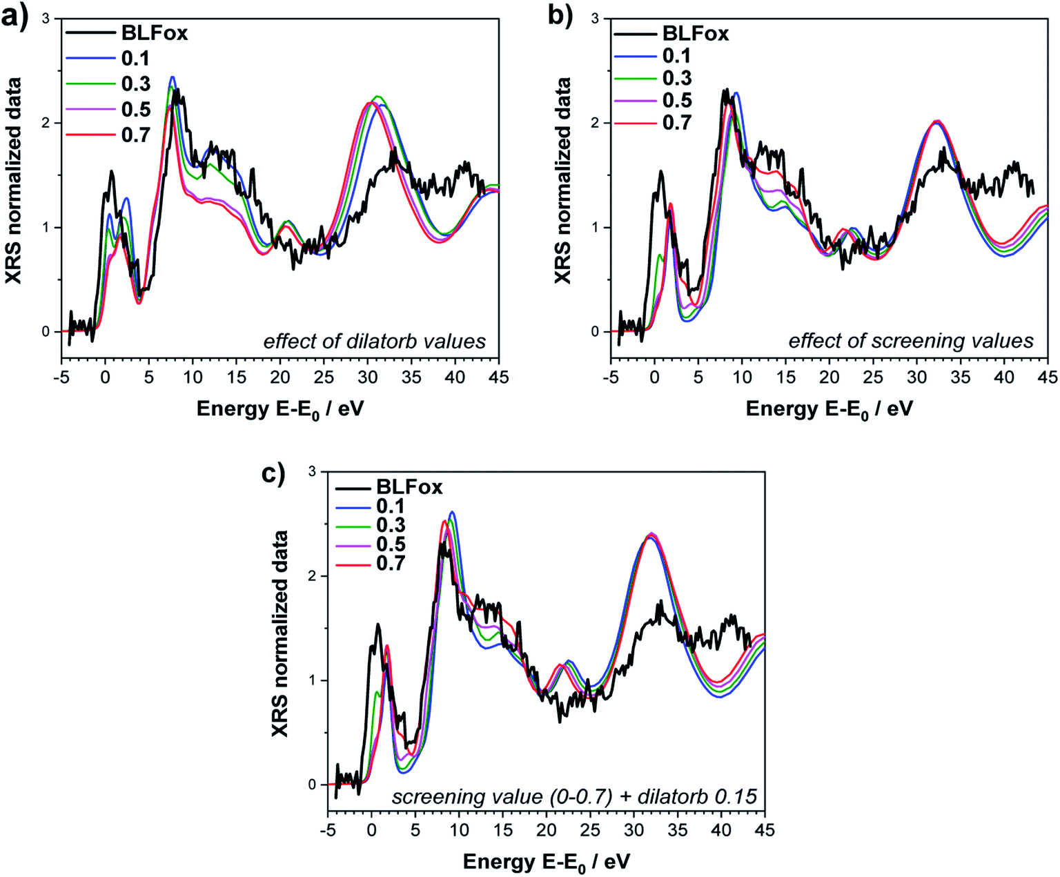 | ||
| Fig. 2 O K-edge of BLFox. Effects of selected values of dilatorb (a) and screening (b) on the simulations. (c) Effect of screening values matched with the best dilatorb value of 0.15. The simulated spectra are not convoluted (convoluted spectra are shown in Fig. 4). | ||
Since the screening parameter reflects to some extent the interaction between the oxygen and the TM d states, its variation, depicted in Fig. 2b, leads to strong changes in the intensity ratio and the mutual position of the O main edge and pre-edge peaks.19 In fact, an increase in the screening value produces a drastic shift of the pre-edge and main peak to higher energies, and also the broad feature at 15 eV is modified. Subsequently, for a defined value of dilatorb, spectra with different values of screening were simulated. The effect of the use of different combined dilatorb and screening values is summarized in Fig. 2c: the best simulation, which minimizes the discrepancy between experimental and calculated spectra, is obtained for dilatorb = 0.15 and screening = 0.6 (cf.Fig. 4).
The impact of screening and dilatorb on the projected DOS is reported in Fig. 3. The most pronounced effect is seen for the Fe 3d states, because they interact most strongly with the O 2p states. In particular, the peak at 3 eV in Fig. 3a shifts to 2 eV with the application of screening and dilatorb, which significantly improves the fitting of the pre-edge peak. The Ba 3d states are modified to a smaller degree, but since they dominate the response at (E − E0) = 5 to 7 eV, this change is also important for the overall fit quality.
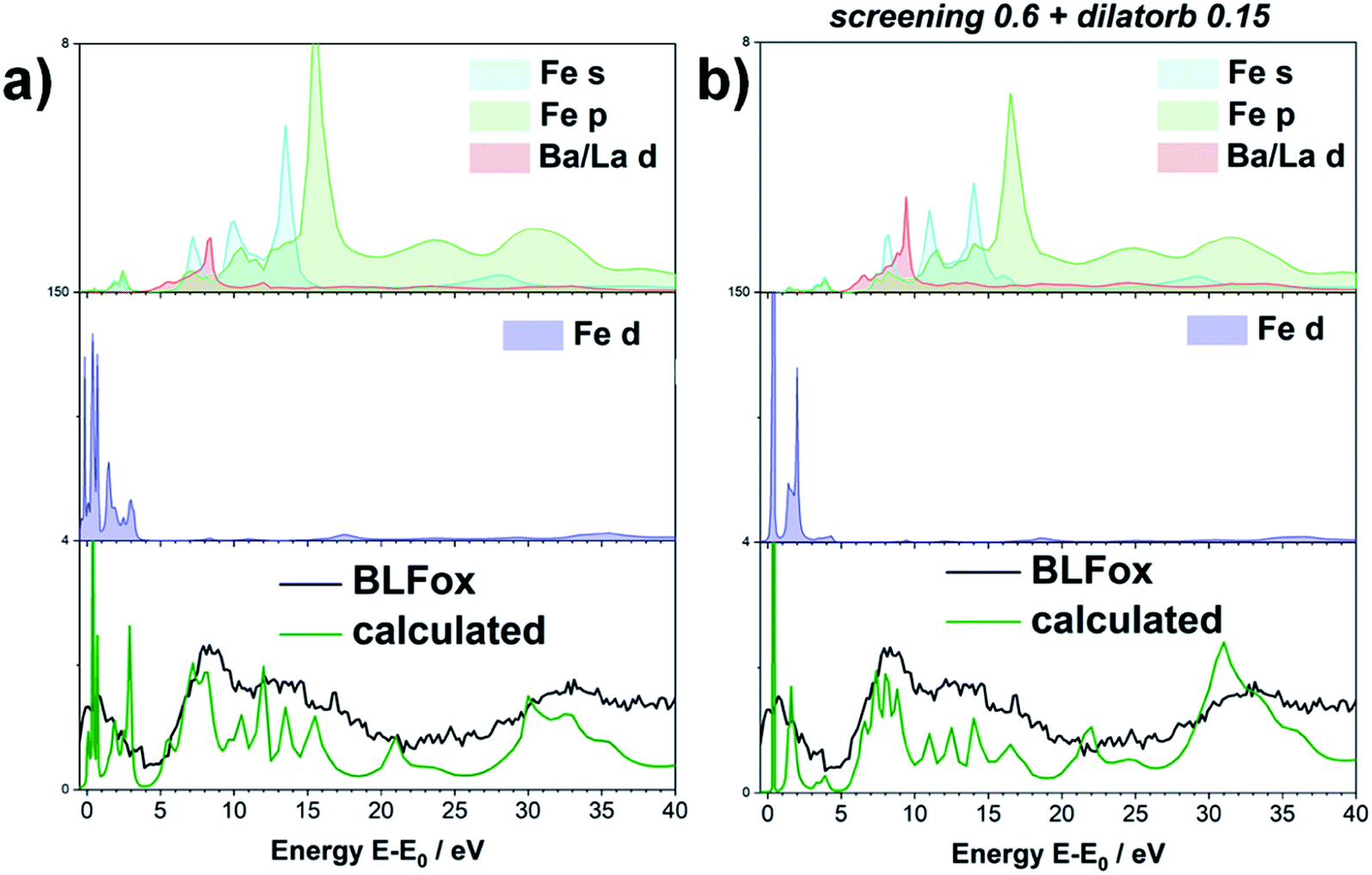 | ||
| Fig. 3 Projected DOS of BLFox (empty states above the Fermi level). s, p, d contribution of the different elements, without (a) and with (b) applying the semi-empirical parameters. The green line is the (unconvoluted) O XRS spectrum calculated from the DOS, and the black line the experimental spectrum. | ||
Having explained the procedure for the undoped case, we now apply the same methodology to examine the doped samples. Within the investigated energy range, all the main features of the electronic band structure around the oxygen K-edge are reasonably well reproduced by applying screening values of 0.6, 0.8 and 0.9 for BLFox, BLFZnox and BFYox, respectively. A dilatorb value of 0.15 was also required for the oxidized samples (undoped and Zn, Y doped).
For the reduced samples, screening is set to 0 and dilatorb is also 0. This means that for the reduced samples the core hole charge is completely screened as the TM ion in the formal 3+ oxidation state withdraws much less charge from O2− and thus no additional screening influence needs to be added by the screening parameter. This situation corresponds to a relatively small interaction with the 3d states of the TMs. In addition, dilatorb 0 indicates a reduced overlap of the hybridized orbital of oxygen with the TM 3d orbitals, which might be related to the larger Fe–O distance as well as the decreased effective Fe charge. The results of the simulations are summarized in Fig. 4, which emphasizes the importance of correcting the calculation result by the screening parameter in particular for the oxidized samples.
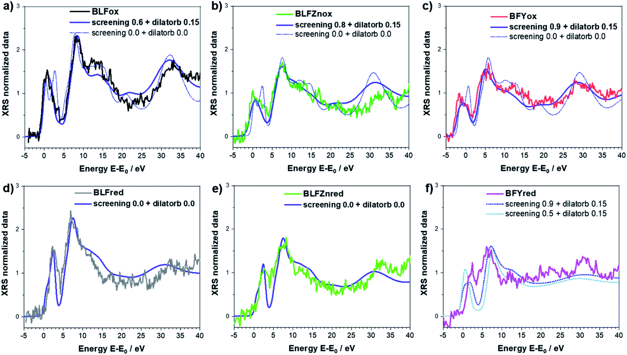 | ||
| Fig. 4 Best simulation (blue solid lines, convolution applied) obtained for BLFox (a), BLFred (b), BLFZnox (c), BLFZnred (d), BFYox (e), and BFYred (f) – for which no parameter set yields good agreement between the simulated and experimental data. The necessity of using the screening and dilatorb parameters for oxidized samples is emphasized in the top panels where the simulations with screening 0 and dilatorb 0 are reported as dashed lines for comparison. | ||
The results suggest that the use of these two parameters can tune the electronic configuration and reproduce the characteristics of the electronic structure in the oxidized samples, as well as the Zn- and Y-doping effect. It is worth noting that the screening parameter value in the oxidized undoped sample is smaller (0.6) than those for Zn- and Y-doped oxidized samples (0.8 and 0.9). This indicates an electron transfer to the TM d orbital so the formal charge of the oxygen ion is less negative in the undoped sample with respect to the doped; in other words, the doping helps to retain the p-character of the oxygen (i.e. the 3d character of the iron) and the hybridization of O(2p)–Fe(3d) is minimized. As already hypothesized in ref. 13, the local distortion (Fe–O–Fe buckling) can very much be the cause of this decreased orbital hybridization. Moreover, this agrees with the proton uptake measurements reported in ref. 12, where Zn- and Y-doped samples exhibit a proton concentration which is 2–3 times higher than that for undoped BLF. Indeed, a more negatively charged oxide ion is more basic and therefore more favorable for proton attachment. The screening value for simulating BFYox is slightly higher than that for BLFZn. This is not necessarily a contradiction to the larger proton uptake of BLFZn. The presence of very strong lattice distortions (the B cation mismatch from ionic radii31 is 0.095 Å for BLFZn and 0.255 Å for BFY) may be detrimental to the proton uptake because of energetically nonequivalent oxygen sites; this is well known e.g. for BaCe1−xYxO3−δ.1
While this method is successful for BLF and BLFZn, it is not able to reproduce the spectral features of BFYred as shown in Fig. S4.† As previously mentioned, the use of semi-empirical parameters helps to tune the electronic configurations connected with small structural rearrangements around the absorber. Therefore, in the case of BFYred, a stronger modification of the oxygen local environment and of the whole oxygen lattice, has to be considered. On the other hand, no significant differences are found at the Y K-edge (cf.Fig. 6 below, indicating the absence of  in the first Y coordination sphere in BFYred).
In the following, we analyze how this distorted B cation environment around the oxygen atoms modifies the O K-edge spectra of BFYred. To simulate possible structures which reproduce the experimental spectra, all the symmetry restrictions are removed, and the B-site cations and/or some oxygen atoms are also shifted from their positions (see Table S1 and Fig. S5 in the ESI†). Several different oxygen arrangements around the cations have been explored, including an oxygen vacancy in the first coordination sphere (actually obtained by setting an unrealistically long Fe–O distance). Changing the oxygen position does not only directly change the local geometry of the O atom but induces a modification of the B cation coordination, which ultimately affects the whole oxygen lattice.
For each trial atomic configuration, the corresponding O K-edge spectrum has been recorded and compared with the experimental data from XRS. For a configuration to be considered valid, the corresponding calculated spectrum has to reproduce, within reasonable agreement, the main features of the edge: (i) peak positions (vertical lines in the plots) and (ii) intensity. The calculations were performed without semi-empirical parameters (i.e. screening = 0 and dilatorb = 0). The results for selected configurations, including the octahedral distortion around the perovskite B site, are shown in Fig. 5: an undistorted (ideal) and a distorted (D) perovskite with iron in 6-fold coordination, a distorted perovskite with iron in 5-fold coordination (B), and the best simulation which is discussed below.
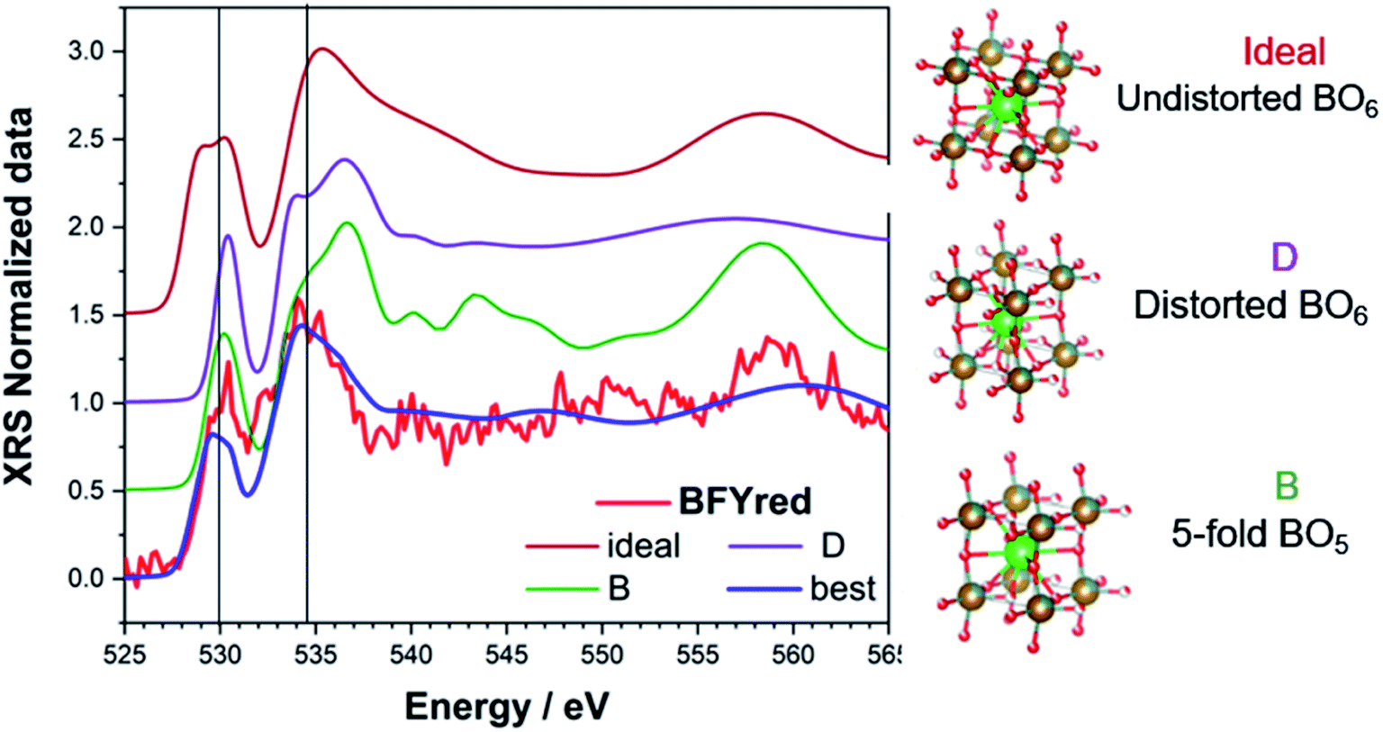 | ||
| Fig. 5 Calculated O K-edge for different reasonable perovskite structures: ideal (undistorted BO6), D (distorted BO6), B (strongly distorted BO5) and best (average of possible configurations with a 5-fold B-site). Atoms in the ball-and-stick sketches: red = O (with partial occupancy), gold/grey = Fe/Y, and green = Ba. | ||
After an initial exploration of the possible oxygen arrangements, our attention is focused on those distorted structures in which the iron exhibits a strongly distorted 5-fold coordination, such as configuration B in Fig. 5. Indeed, the latter show the best agreement with the experimental data. In fact, DFT calculations show that for BFYred the configuration  is energetically much more favorable than
  13 Already in undoped BLFred most Fe is pentacoordinated simply from a random
  distribution. However, the combination of a strongly oversized dopant Y3+ (larger than Fe3+ as well as Zn2+) with the fact that Y3+ repels the
  leads to an even higher vacancy concentration around Fe and in particular a much stronger distortion. The best agreement with the experimental data is achieved for an average of several simulated spectra (cf. Fig. S6†) obtained starting from the 5-fold configurations (B) and by slightly modifying the xyz coordinates.
The agreement between calculations and the experiment is quite satisfactory. The obtained structure is reported in Table S1.† A possible configuration with iron in 4-fold coordination (which occurs in some oxides, see e.g., ref. 32 and 33) was also tested but its agreement with the experimental data is not satisfactory. However, some minor contribution from this atomic arrangement around the B site cannot be totally excluded.
The necessity to include strongly distorted pentacoordinated Fe to reproduce the XRS spectra proves that a deep structural reorganization for the iron atoms occurs in BFYred. Keeping in mind that no variation was detected at the Y K-edge, while the Fe K-edge shows some changes upon reduction, one can conclude that the iron local environment is the one mainly involved in the reduction process, as it constitutes the preferential location for the oxygen vacancies.
The fact that in BFYred the oxygen vacancies cluster around the iron atoms can affect the proton uptake, because it creates strongly inequivalent oxygen sites with different hydration energetics. This could explain the lower proton uptake of BFY compared to BLFZn although both materials have a significantly disordered local environment, and comparably low TM–O covalency. This difference is also reflected in the thermodynamics of hydration: the Zn-doped composition has a more negative hydration enthalpy (−86 kJ mol−1) compared to the Y-doped one (−71 kJ mol−1).12 In principle, a preferential  clustering could also affect other enthalpies such as the oxidation enthalpy. However, in the relevant range of intermediate temperatures, barium ferrate perovskites show deviations from ideally dilute defect chemistry (also related to the hole delocalization) which leads to a bending of the corresponding van't Hoff plots,11 resulting in comparable large uncertainties, which prevent a meaningful comparison of oxidation enthalpies between BLF, BLFZn, and BFY.
For the specific materials investigated here, a temperature-dependent measurement of the O K-edge is not expected to yield much additional insight, because the repulsion of  from the first coordination shell of Y is so strong (1.08 eV according to DFT results in ref. 13) that it can hardly be overcome at the typical hydration or operating temperatures of these materials. On the other hand, the attractive
  interaction is so weak (0.11 eV according to DFT13) that a random
  arrangement is a reasonable approximation at all T.
3.2 XANES of Fe, Zn and Y K-edges
The Fe K-edge XANES evidences that no particular variation of the TM(Fe)3d electronic states occurs between oxidized and reduced samples, implying that upon oxidation the Fe ions remain very close to the formal 3+ oxidation state, and, from what is shown in Section 3.1, the positive charge (electron hole) retains oxygen 2p character in the electronic configuration. Fig. 6 shows the XANES spectra at the Fe, Zn, and Y K-edges for all investigated samples. At the Fe K-edge (Fig. 6a), the undoped samples BLFox and BLFred show the strongest variation in terms of peak position and intensity, which nevertheless remains smaller than that observed for the O K-edge. In contrast, the reduction only has a small effect on the doped samples. However, Zn or Y doping modifies the intensity of the main XANES peak (white line at the Fe K-edge) which is remarkably reduced in the doped samples (inset in Fig. 6b). On the other hand, at the Zn K-edge (Fig. 6c) small but significant changes are visible in the white line. No variations are detected at the Y K-edge (Fig. 6d).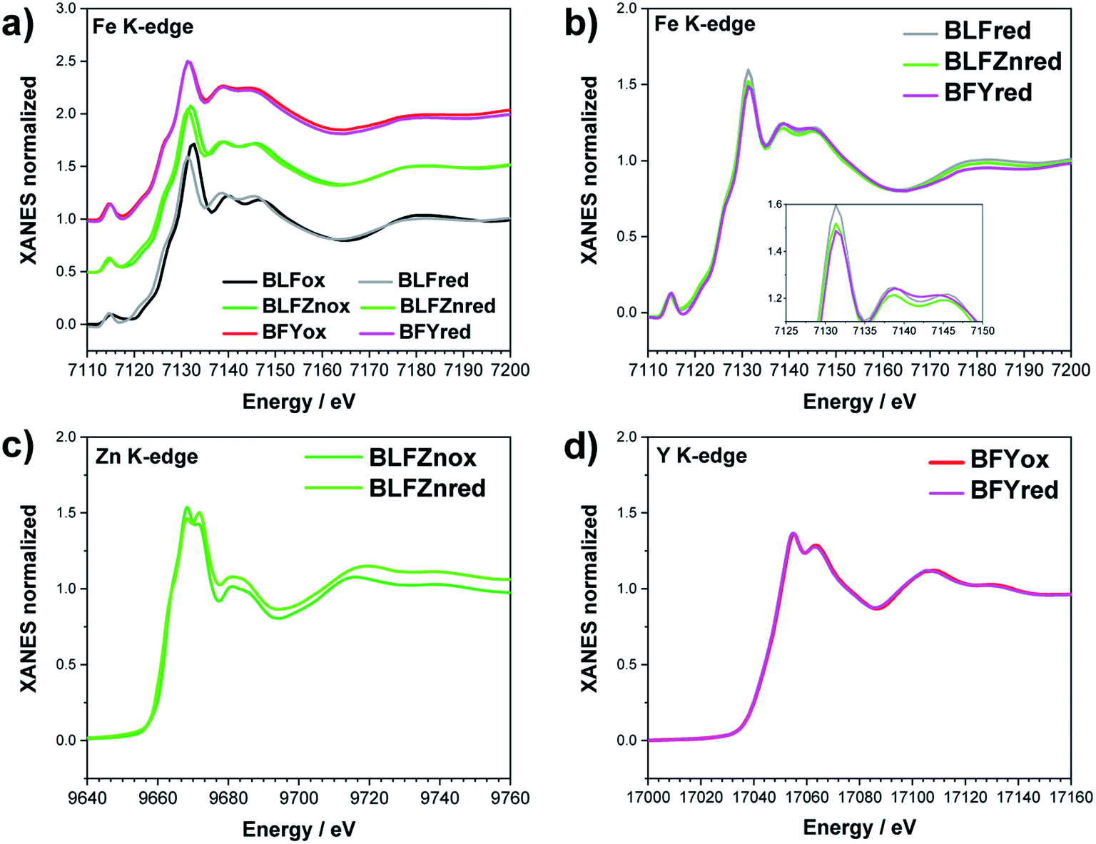 | ||
| Fig. 6 XANES Fe K-edge spectra of all samples (a and b), Zn K-edge (c), and Y K-edge (d). The inset in (b) shows the decrease of the white line intensity for the reduced doped samples. | ||
As reported in the detailed EXAFS study of these samples,13 the partial replacement of iron in the B-site by the larger Y3+/Zn2+, which are less charged, leaves more electron density at the oxide ions. So, in the doped samples iron is closer to the formal 3+ oxidation state even for fully oxidized samples, compared to BLF, and thus the Fe XANES edge position differs less between oxidized and reduced samples. In contrast to oxidized BLF, EXAFS shows that for doped oxidized samples the partial substitution of Fe by Y3+, and even more Zn2+, leads to strong static disorder and buckling of the B–O–B connection. The high oxygen vacancy concentration in the reduced samples further increases the overall local disorder.13
FDMNES analysis involving semi-empirical parameters was also used for analyzing the Fe K-edge data. At this edge, the most important variation is the lowering of the white line (see Fig. 6b). As discussed for the O K-edge, this method can only work with moderate structural and electronic rearrangements. However, after reduction or in the presence of Zn, Y doping, the local environment of iron is strongly modified.13 As a consequence, the use of screening and dilatorb parameters does not yield completely satisfactory results (an example is reported for BLFox, BFYox and BFYred in Fig. S7†). Therefore, assuming that the geometrical modifications reported at the O K-edge are also valid for the iron environment, we calculated the spectrum of the iron in 5-fold arrangement without dilatorb or screening. This was subsequently added with a suitable weighting factor to the simulated signal of the ideal (6-fold) structure, initially used for simulating BLFox (dilatorb 0.1 and screening 0.7, reported in Fig. S7†).
The obtained semi-empirical parameter values for the Fe K-edge of BLFox significantly differ from those achieved for the O K-edge. As described in the previous section, the screening value describes the electron density exchange between the absorber and its neighbors. Therefore, it would be straightforward to expect rather similar values. However, one has to keep in mind that the local environments probed at the O and Fe K-edges are quite different, since through oxygen one probes all the different B-site cations. Hence, the screening value needed to fit the O K-edge has to take into account all O–TM interactions including also Zn and Y contributions. On the other hand, the screening at the Fe K-edge only reflects the Fe–O interaction. This difference between the edges is even more pronounced for the reduced samples. Upon reduction, the iron environment changes, whilst oxygen is removed from the lattice leaving vacancies behind. Accordingly, the impact on the charge transfer and hence on the screening parameter must considerably differ for the two edges.
Iron in doped and reduced samples can exhibit all possible structural configurations from the ideal to the five-fold coordinated arrangement. The latter represents the strongest distortion detected for the iron local environment (however, the presence of minor contributions from other arrangements cannot be fully excluded). Thus, by suitably summing up these two extreme configurations, the average iron local arrangement in the different samples can be emulated. This procedure also assumes that the oxygen vacancies mainly formed upon the reduction treatment and to a smaller degree by Zn- or Y-doping are largely located in the vicinity of iron (the concentration of  pairs would change only slightly when
  avoid the dopant as in the case of Y3+). The results of this procedure for BLFox, BLFred, BLFZnred and BFYred are reported in Fig. 7.
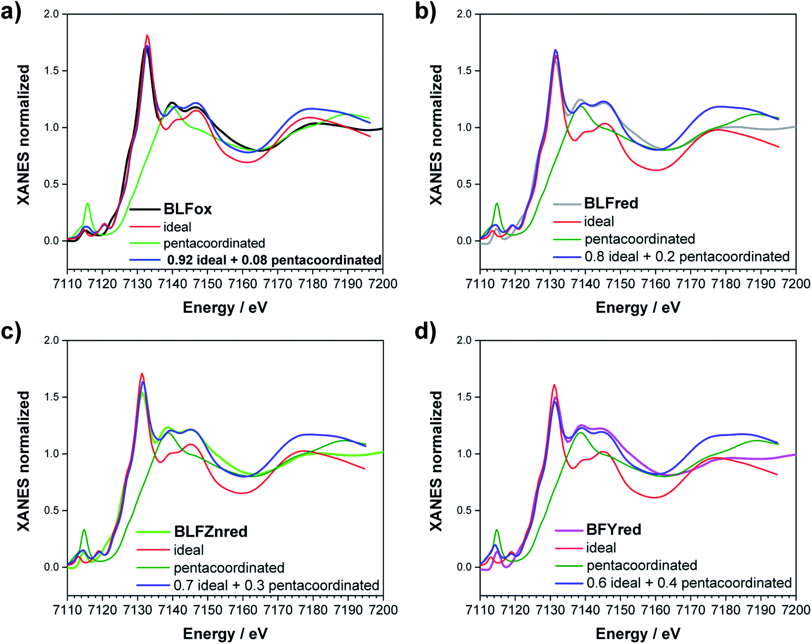 | ||
| Fig. 7 Fe K-edge XANES simulation of (a) BLFox, (b) BLFred, (c) BLFZnred and (d) BFYred. The best simulations are obtained combining 5-fold (green) and 6-fold (red) contributions. The best-weighted sum of the two components is reported in blue. | ||
For BLFox, it is possible to reproduce the experimental data by summing 92% of the ideal structure (screening 0.7 and dilatorb 0.1) and 8% of the penta-coordinated one (no dilatorb or screening). Here, the amount of distorted structure needed to achieve a satisfactory simulation is sensibly lower than that for the other samples, suggesting that just very small modification of the iron local environment occurs, as already expected from ref. 13.
The experimental BLFred spectrum is best simulated by combining 80% of the ideal structure (dilatorb 0.1 and screening 0.7) and 20% of the penta-coordinated arrangement (no dilatorb or screening). Interestingly, the observed white line decrease correlates with the increased contribution of the distorted component, which turns into 30 and 40% for the Zn- and Y-doped samples, respectively (Fig. 7c and d). This result agrees with the high probability of having the iron in 5-fold coordination in this structure considering the vacancy concentration of the samples and their arrangement in the structure. The fact that BFY shows a higher percentage of the distorted component compared to BLFZn is ascribed to the different oxygen vacancy arrangement in the two systems. As mentioned in Section 3.2, the  configuration is energetically more favored than
  Instead,
  prevails for BLFZn.13 Therefore, we can conclude that there is more iron in 5-fold coordination in BFY than in BLFZn.
Zn and Y K-edges were analyzed analogously. In the case of Zn, a screening value of 0 and dilatorb values of 0.1 and 0.2 were applied for simulating the oxidized and reduced samples. This suggests a slight increase of the orbital overlap. No variations are evident at the Y K-edge, where the same values for screening and dilatorb parameters were used for both oxidized and reduced samples. The value of screening 0.1 suggests a retained electronic density on the Y atom, meaning that the yttrium atoms are not strongly participating in the charge transfer with the oxide ions. The results are reported in Fig. 8.
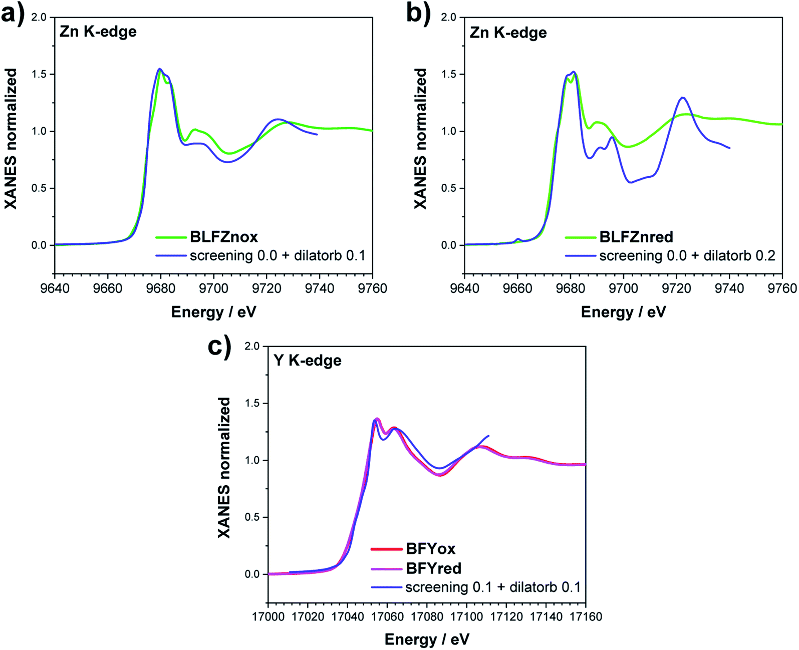 | ||
| Fig. 8 XANES simulation of (a and b) the Zn K-edge of BLFZn and (c) the Y K-edge of BFY. | ||
4. Conclusion
The present investigation of (Ba,La)(Fe,Zn,Y)O3−δ perovskites sheds light on the modification of the electronic structure (in particular of oxygen states) due to the introduction of oversized Zn, Y dopants at the Fe site. This further allows us to understand the specific effect of these dopants on proton uptake into PCFC cathode materials.The O K-edge features were simulated using a combination of SCF and DFT calculations and two semi-empirical parameters (screening and dilatorb), which help to quantify the changes of covalency and charge transfer of the Fe–O bonds, and thus also the oxygen ion basicity. The undoped oxidized Ba0.95La0.05FeO3 sample has a lower screening parameter than the Zn, Y doped oxidized samples, which corresponds to a less negative charge of oxygen for undoped Ba0.95La0.05FeO3. This affects negatively the proton uptake since it implies a lower basicity of the oxide ions. The larger screening parameter and respective more negative charge (and higher basicity) on O for the doped samples can be ascribed to the B–O–B buckling (particularly strong for Fe–O–Fe), which disfavors the Fe(3d)–O(2p) orbital overlap. The O XRS spectra of reduced Ba0.95La0.05FeO2.525 and Ba0.95La0.05Fe0.8Zn0.2O2.425 can easily be simulated without any semi-empirical parameters. BaFe0.8Y0.2O2.50 is more complex owing to large structural rearrangements and requires explicit introduction of pentacoordinate iron. While in Zn-doped samples the oxygen vacancies are distributed randomly, for Y doping they rather cluster around iron indicating that  is energetically more favorable than
  This energetic difference could explain the lower proton uptake of the Y-doped composition with respect to Zn doping, even if both have comparably low oxygen–TM interaction and a comparably disordered local environment. The Zn and Y K-edges of the doped samples could be modeled using the screening and dilatorb parameters. Owing to the larger local disorder around iron, the simulations of the Fe K-edge require summing two components arising from 5-fold and 6-fold environments, with a higher fraction of the more distorted 5-fold coordination for Zn- and Y-doped samples.
In summary, we presented a consistent methodology (and its limitations) for simulating the oxygen and metal K-edges, which we expect to be largely applicable also beyond BaFeO3−δ perovskites. We demonstrated that it is possible to quantify the Fe–O covalency based on the analysis of XRS and XANES spectra. We further showed that the differences due to oxidation/reduction and to the introduction of oversized dopants can be correlated with the proton uptake for these materials, which helps to optimize PCFC cathode materials.
Conflicts of interest
There are no conflicts of interest to declare.Acknowledgements
We thank Helga Hoier (MPI for Solid State Research, Stuttgart) for XRD, Samir Hammou (MPI for Intelligent Systems, Stuttgart) for ICP-OES, and Chiara Cavallari (ESRF, Grenoble) for support at the beamline ID20. ESRF is acknowledged for providing synchrotron radiation beamtime at the beamlines ID20 and BM26A. Open Access funding provided by the Max Planck Society.References
- K. D. Kreuer, Annu. Rev. Mater. Res., 2003, 33, 333 CrossRef CAS.
- R. Merkle, D. Poetzsch and J. Maier, ECS Trans., 2015, 66, 95 CrossRef CAS.
- J. Kim, S. Sengodan, G. Kwon, D. Ding, J. Shin, M. L Liu and G. Kim, ChemSusChem, 2014, 7, 2811 CrossRef CAS PubMed.
- C. Duan, J. Tong, M. Shang, S. Nikodemski, M. Sanders, S. Ricote, A. Almansoori and R. O'Hayre, Science , 2015, 349, 1321 CrossRef CAS PubMed.
- K. Bae, D. Y. Jang, H. J. Choi, D. Kim, J. Hong, B. K. Kim, J. H. Lee, J. W. Son and J. H. Shim, Nat. Commun., 2017, 8, 14553 CrossRef CAS PubMed.
- S. Choi, C. J. Kucharzcyk, X. G. Liang, X. H. Zhang, I. Takeuchi, H. I. Ji and S. M. Haile, Nat. Energy, 2018, 3, 202 CrossRef CAS.
- H. An, H. W. Lee, B. K. Kim, J. W. Son, K. J. Yoon, H. Kim, D. Shin, H. I. Ji and J. H. Lee, Nat. Energy, 2018, 3, 870 CrossRef CAS.
- L. Lei, J. Zhang, Z. Yuan, J. Liu, M. Ni and F. Chen, Adv. Funct. Mater., 2019, 29, 1903805 CrossRef.
- Y. Zhang, R. Knibbe, J. Sunarso, Y. Zhong, W. Zhou, Z. Shao and Z. Zhu, Adv. Mater., 2017, 29, 1700132 CrossRef PubMed.
- C. Duan, J. Huang, N. Sullivan and R. O'Hayre, Appl. Phys. Rev., 2020, 7, 011314 CAS.
- R. Merkle, M. F. Hoedl, G. Raimondi, R. Zohourian and J. Maier, Annu. Rev. Mater. Res., 2021, 51, 461 CrossRef CAS.
- R. Zohourian, R. Merkle, G. Raimondi and J. Maier, Adv. Funct. Mater., 2018, 28, 1801241 CrossRef.
- G. Raimondi, F. Giannici, A. Longo, R. Merkle, A. Chiara, M. F. Hoedl, A. Martorana and J. Maier, Chem. Mater., 2020, 32, 8502 CrossRef CAS.
- J. Suntivich, W. T. Hong, J. L. Lee, J. M. Rondinelli, A. Yang, J. B. Goodenough, B. Dabrowski, J. W. Freeland and Y. Shao-Horn, J. Phys. Chem. C, 2014, 118, 1856 CrossRef CAS.
- M. B. Salamon and M. Jaime, Rev. Mod. Phys., 2001, 73, 583 CrossRef CAS.
- S. Meng, J. Tong and R. A. O'Hayre, RSC Adv., 2013, 36, 15769 Search PubMed.
- F. Dong, D. Chen, Y. Chen, Q. Zhao and Z. Shao, J. Mater. Chem., 2012, 22, 15071 RSC.
- C. Chen, D. Chen, Y. Gao, Z. Shao and F. Ciucci, J. Mater. Chem. A, 2014, 2, 14154 RSC.
- J. Yoly, Phys. Rev. B: Condens. Matter Mater. Phys., 2001, 63, 125120 CrossRef.
- J. Yoly, C. Cavallari, S. A. Guda and C. J. Sahle, J. Chem. Theory Comput., 2017, 13, 2172 CrossRef PubMed.
- J. Yoly, D. Cabaret, H. Renevier and C. Natoli, Phys. Rev. Lett., 1999, 82, 2398 CrossRef.
- C. J. Sahle, A. Mirone, J. Niskanen, J. Inkinen, M. Krisch and S. Huotari, J. Synchrotron Radiat., 2015, 22, 400 CrossRef CAS PubMed.
- S. Huotari, C. J. Sahle, C. Henriquet, A. Al-Zein, K. Martel, L. Simonelli, R. Verbeni, H. Gonzalez, M. C. Lagier, C. Ponchut, M. Moretti Sala, M. Krisch and G. Monaco, J. Synchrotron Radiat., 2017, 24, 521 CrossRef CAS PubMed.
- Y. Meng, X. W. Liu, C. F. Huo, W. P. Guo, D. B. Cao, Q. Peng, A. Dearden, X. Gonze, Y. Yang, J. Wang, H. Jiao, Y. Li and X. D. Wen, J. Chem. Theory Comput., 2016, 12, 5132 CrossRef CAS PubMed.
- P. G. Radaelli, G. Iannone, M. Marezio, H. Y. Hwang, S. W. Cheong, J. D. Jorgensen and D. N. Argyriou, Phys. Rev. B: Condens. Matter Mater. Phys., 1997, 56, 8265 CrossRef CAS.
- C. J. Sahle, A. Mirone, J. Niskanen, J. Inkinen, M. Krisch and S. Huotari, J. Synchrotron Radiat., 2015, 22, 400 CrossRef CAS PubMed.
- A. Longo, S. A. Theofanidis, C. Cavallari, N. V. Srinath, J. Hu, H. Poelman, M. K. Sabbe, C. J. Sahle, G. B. Marin and V. V. Galvita, ACS Catal., 2020, 10, 6613 CrossRef CAS.
- M. Fehse, C. J. Sahle, M. P. Hogan, C. Cavallari, E. M. Kelder, M. Alfredsson and A. Longo, J. Phys. Chem. C, 2019, 40, 24396 CrossRef.
- M. Benfatto and C. R. Natoli, J. Non-Cryst. Solids, 1987, 35, 319 CrossRef.
- F. Frati, M. O. J. Y. Hunault and F. M. F. de Groot, Chem. Rev., 2020, 120, 4056 CrossRef CAS PubMed.
- R. D. Shannon, Acta Crystallogr., 1976, 32, 751 CrossRef.
- S. Wollstadt, Y. Ikeda, A. Sarkar, S. Vasala, C. Fasel, L. Alff, R. Kruk, B. Grabowski and O. Clemens, Inorg. Chem., 2021, 15, 10923 CrossRef PubMed.
- K. Luo, R. D. Johnson, T. T. Tran, P. S. Halasyamani, P. G. Radaelli and M. A. Hayward, Chem. Mater., 2013, 25, 1800 CrossRef CAS.
Footnote |
| † Electronic supplementary information (ESI) available. See DOI: 10.1039/d1ta10211g |
| This journal is © The Royal Society of Chemistry 2022 |