 Open Access Article
Hollow MoC/NC sphere for electromagnetic wave attenuation: direct observation of interfacial polarization on nanoscale hetero-interfaces†
Wenhuan
Huang
 *a,
Wenming
Gao
ab,
Shouwei
Zuo
ab,
Luxi
Zhang
a,
Ke
Pei
d,
Panbo
Liu
 c,
Renchao
Che
 *d and
Huabin
Zhang
 *b
*b
aKey Laboratory of Chemical Additives for China National Light Industry, College of Chemistry and Chemical Engineering, Shaanxi University of Science and Technology, Xi'an 710021, China. E-mail: huangwenhuan@sust.edu.cn
bKAUST Catalysis Center, King Abdullah University of Science and Technology, Thuwal, 23955-6900, Kingdom of Saudi Arabia. E-mail: huabin.zhang@kaust.edu.sa
cSchool of Chemistry and Chemical Engineering, Northwestern Polytechnical University, Xi'an 710129, China
dLaboratory of Advanced Materials, Shanghai Key Lab of Molecular Catalysis and Innovative Materials, Fudan University, Shanghai 200438, P. R. China. E-mail: rcche@fudan.edu.cn
First published on 9th December 2021
Abstract
Carbon-based composites with hetero-interfaces is a group of promising electromagnetic wave absorbing materials (EWAMs) for their excellent dielectric loss. For developing this kind of EWAMs, in situ construction of hetero-interfaces and revealing its attenuation mechanism are of great importance, but remain challenges. Herein, a MoC-incorporated N-doped carbon hollow sphere (H-MoC/NC) with uniformly distributed nanoscale MoC/NC hetero-interfaces was precisely synthesized for evaluating the interfacial polarization in electromagnetic wave attenuation. The Mo defects in MoC not only contributed to the impedance matching through the hollow shell, but also accelerated the charge transfers, displaying an enhanced interfacial charge polarization. More importantly, this polarized charge distribution on the MoC(−)/carbon(+) interface was observed for the first time directly through the hologram at a nanometer scale. The atomic-level understanding of interfacial polarization in the electromagnetic attenuation process will greatly promote the development of designing and synthesizing non-magnetic carbon-based EWAMs.
Introduction
For solving the spatial electromagnetic radiation, in recent decades, scientists have developed numerous groups of highly efficient electromagnetic wave absorbing materials (EWAMs), including carbon-based materials,1–3 silicon carbides,4,5 transition metal-based carbides,6,7 oxides,8,9 sulfides,10,11 nitrides,12,13 and ferromagnetic metal-based materials.14–16 In the electromagnetic wave absorbing process, the combination of permittivity and permeability directly determines the electromagnetic wave storage and attenuation capacities of the materials.17–21 It is an overall synergetic effect of intrinsic electrical and magnetic characteristics modulated by chemical-components, electron conductivity, electromagnetic balance, and micro-nano structure.22–27 Therefore, for the rational design and synthesis of EMAMs with the target properties, investigating the mechanism of attenuation contribution of each part is necessary.11,28–31The permeability of the materials generally can be evaluated by magnetizability and saturation magnetization from magnetic hysteresis loops.14,32,33 Moreover, off-axis electron holography and micromagnetic simulation can also be utilized to confirm the magnetic coupling between metal nanoparticles.14,33 As another part of attenuation contribution, permittivity attenuation consists of several parts, including conduction loss, dipole polarization loss, and interfacial polarization loss.6,34 Among them, conduction loss is mainly due to the conductivity of the materials, which can be tested through a four-probe resistance meter.17,35 The dipole polarization is attributed to the chemical bond or atom–atom interaction in hybrids, which can be investigated by X-ray photoelectron- and Fourier transform infrared spectroscopy.34,36 For studying the attenuation mechanism of interfacial polarization, numerous physical and chemical strategies have been employed for constructing hetero interfaces in composites.2,37–40 Some interfacial interactions have already been investigated, such as the coupling between Sn-graphitized/amorphous carbon was evaluated by EXAFS,17 and the interaction in the 2H-MoS2/1T-MoS2 interface was evaluated by the EPR results.10 Some excellent synthesis strategies for constructing hetero-interfaces have been applied for enhancing the conversion of electrochemical energy and electromagnetic wave energy.41–46 Recently, the polarized charge distribution of ZnO/Ni interfaces was directly observed by a hologram, but the visible range of polarization interfaces was about 100 nm, which lay between hetero-particles.22 Under such circumstances, the internal polarization mechanism at an atomic level on a hetero-interface cannot be directly observed and investigated.9,17,36,47
Herein, nanoscale hetero-interfaces in a MoC-incorporated N-doped carbon hollow sphere (H-MoC/NC) were elaborately designed and constructed for investigating the internal mechanism of interfacial polarization and clarifying its contribution in permittivity attenuation.10 As a unique feature, a ZnMo-bimetallic hybrid zeolitic imidazolate framework (HZIF-ZnMo), which is a representative of a new class of metal organic frameworks (MOF) with orderly arranged MoO4 in the crystalline structure of the zeolite imidazolate framework (ZIF), was employed as a precursor to construct MoC/NC hetero-interfaces.48,49 Moreover, by introducing a chemical etching step, the hollow sphere (H-MoC/NC) was assembled to obtain nanoscale MoC/NC interfaces and survey the interfacial polarization mechanism at the atomic level.15 As a result, the Mo defects on the hetero-interfaces were observed, which resulted in the interfacial polarization by charge transfer and charge accumulation. More importantly, this interfacial charge polarization at the MoC/NC interface around ∼1 nm was directly observed through the hologram. To the best our knowledge, it is the first time to investigate and understand the interfacial polarization from the atomic level.
Experimental
Synthetic procedures
Characterization and data analysis
![[thin space (1/6-em)]](https://www.rsc.org/images/entities/char_2009.gif) :
:![[thin space (1/6-em)]](https://www.rsc.org/images/entities/char_2009.gif) 17 (loading amount of 15 wt%), and then, the mixture was pressed into a toroidal shape with an inner diameter of 2.0 mm and an outer diameter of 7.0 mm.
17 (loading amount of 15 wt%), and then, the mixture was pressed into a toroidal shape with an inner diameter of 2.0 mm and an outer diameter of 7.0 mm.
Results and discussion
Synthesis and structural characterization
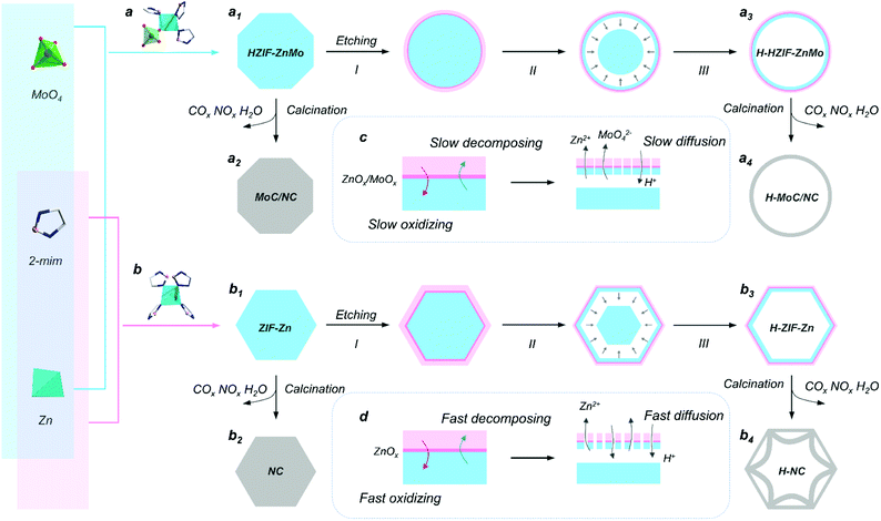
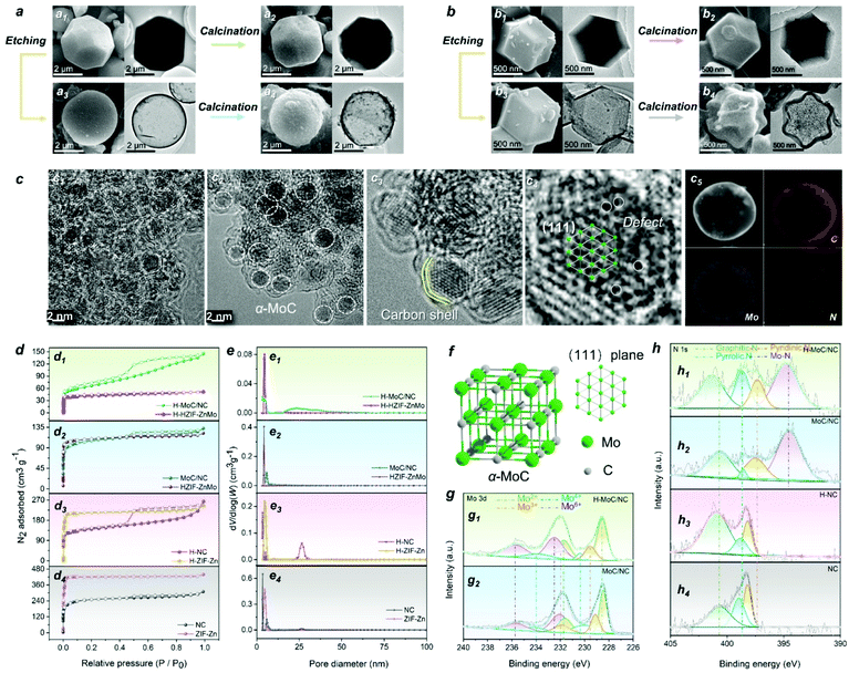
The synthesis procedure of the hollow MoC-incorporated N-doped carbon (H-MoC/NC) sphere is illustrated in Fig. 1. For evaluating the attenuation mechanism of the MoC/NC hetero-interface in the hollow structure, solid MoC-incorporated N-doped carbon (MoC/NC), hollow N-doped carbon (H-NC) and solid N-doped carbon (NC) were elaborately synthesized and characterized as contrast samples. The HZIF-ZnMo was crystallized from MoO4, Zn and imidazole (Fig. 1a1), while ZIF-Zn was assembled from Zn and imidazole (Fig. 1b1), which, as precursors (Fig. S1†), were calcinated at 900 °C under nitrogen flow, and transformed into solid MoC/NC and NC polyhedrons (Fig. 1a2 and b2). As shown in Fig. 2a and b, solid MoC/NC and NC kept the original shapes of HZIF-ZnMo and ZIF-Zn, showing a chamfered cube and a rhombohedral dodecahedron with diameters of 2 μm and 500 nm, respectively. The uniformly distributed elements were evaluated by EDS mapping in Fig. S3, S4, S7 and S8.†For constructing the hollow structure, an acid etching process was employed, which successfully generated the HZIF-ZnMo hollow sphere (H-HZIF-ZnMo) and the ZIF-Zn hollow rhombohedral dodecahedron (H-ZIF-Zn) (Fig. 1a3 and b3).50,51 SEM and TEM results in Fig. 2b3 indicate that H-ZIF-Zn perfectly inherited the morphology of ZIF-Zn with an ultra-thin shell after the etching process. As illustrated in Fig. 1d, the fast formed ZnOx shell protected the surface of ZIF-Zn; hence, a hollow polyhedron was formed during a fast ion-diffusion process. On the contrary, owing to the higher chemical stability than those of ZIF-Zn, HZIF-ZnMo was slowly decomposed and accompanied by the formation of a ZnOx/MoOx oxide shell, displaying a slow ion-diffusion speed (Fig. 1c).48,52,53 This slow surface solvation process generated a hollow sphere morphology of H-HZIF-ZnMo (Fig. 2a3). Then, after the same calcination condition at 900 °C, H-HZIF-ZnMo and H-ZIF-Zn were in situ transformed into hollow structural H-MoC/NC and H-NC particles (Fig. 2a4 and b4). The good thermal stability of HZIF-ZnMo and the MoC component resulted in the remained hollow sphere morphology of H-MoC/NC (Fig. 2a4). However, during the fast decomposition of H-ZIF-Zn and departure of the gases, the shrunken hollow rhombohedral dodecahedron morphology of H-NC (Fig. 2b4) was obtained. These results were also confirmed by IV-type N2 sorption isotherm curves and micropores in pore diameter results (Fig. 2d and e). The pore size of the hollow structural H-MoC/NC and H-NC samples were obviously larger than that of solid MoC/NC and NC samples. The higher BET surface area of H-MoC/NC (582.425 m2 g−1) and that of un-calcinated H-HZIF-ZnMo (217.129 m2 g−1) meant the increase in the pore volume and the maintained hollow sphere morphology after the calcination. Moreover, the smaller surface area of H-NC (960.190 m2 g−1) than that of un-calcinated H-ZIF-Zn (1003.293 m2 g−1) proved the decrease in the pore volume and the shrinkage of H-NC.
HZIF-ZnMo was selected as a precursor for in situ synthesizing MoC-incorporated carbon owing to its high-crystalline structure of ordered arranged Zn, Mo and organic ligands. The crystalline phase of MoC and graphite carbon in both H-MoC/NC and MoC/NC were confirmed by the PXRD pattern (Fig. S11†). The wide peak at 21.3 corresponds to the (002) plane of graphite carbon, while the peaks at 36.6, 42.4, 61.8, and 74.3 are correspond to the (111), (200), (220), and (311) planes of α-MoC (JCPDS-01-089-2868). As is known, the crystalline phase conversion for molybdenum carbide is observed during the high-temperature calcination process at 900 °C. Herein, a programmed heating process was employed for obtaining the pure phase of α-MoC, in which Mo and C atoms crystalized in the cubic Fm![[3 with combining macron]](https://www.rsc.org/images/entities/char_0033_0304.gif) m space group with the fcc stacking mode (Fig. 2f). The ID/IG ratio of D band (1350 cm−1) and G band (1590 cm−1) peaks were calculated from the Raman results (Fig. S12†) for characterizing the amount of the disordered/defected carbon and sp2 carbon. The calculated higher ID/IG values for H-MoC/NC and H-NC (1.07 and 1.12) than those of solid MoC/NC and NC (0.94 and 1.03) indicates that the structural disorder and defects of the carbon matrix were more apparent in hollow structural samples.
m space group with the fcc stacking mode (Fig. 2f). The ID/IG ratio of D band (1350 cm−1) and G band (1590 cm−1) peaks were calculated from the Raman results (Fig. S12†) for characterizing the amount of the disordered/defected carbon and sp2 carbon. The calculated higher ID/IG values for H-MoC/NC and H-NC (1.07 and 1.12) than those of solid MoC/NC and NC (0.94 and 1.03) indicates that the structural disorder and defects of the carbon matrix were more apparent in hollow structural samples.
On the other hand, chemical etching and calcination was used for constructing atomic defects and nanoscale hetero-interfaces. As the HRTEM results shown in Fig. 2c1, abundant nanoscale H-MoC/NC hetero-interfaces were observed. MoC nanoparticles with the diameter of 2.5 nm were embedded with the carbon shells (Fig. 2c2 and c3). The atom arrangement highly matched with the (111) lattice plane of the MoC crystalline structure (Fig. 2c4). In the MoC particle, numerous Mo defects in the lattice were observed, which benefited the electron hopping and charge transfer. Then, this was confirmed by the XPS results (Fig. 2g and h). The Mo 3d XPS spectra split into 3d5/2 and 3d3/2 peaks, which were further fitted into four oxidation states peaks of Mo2+, Mo3+, Mo4+ and Mo6+ (Fig. 2g). Owing to the existence of and Mo–C bonds in α-MoC, the Mo2+ peaks were observed. The Mo defects in the crystalline brought the valence state increase of the adjacent Mo atom sites, such as the emerging of Mo3+, while the existence of Mo4+ and Mo6+ was attributed to the surface oxidation of MoOx (MoO2 and MoO3). Compared with MoC/NC, the higher amount of high-valent Mo atoms and positive shifts of all Mo peaks for H-MoC/NC were attributed to the Mo defects, valence changes on the Mo–N/Mo–O bonds at the hetero-interfaces. The N 1s spectra for H-MoC/NC and MoC/NC (Fig. 2h) exhibited pyridinic N, pyrrolic N, graphitic and Mo–N peaks. The high amount of pyrrolic N, positive shift of graphitic N and Mo–N, and negative shift of pyridinic N in H-MoC/NC indicated the defects and disordered atoms. The doped N atoms in the carbon matrix provided the dipole polarization in the graphite carbon. The C 1s XPS spectra (Fig. S13†) displayed multiple C–O pieces in the hollow structural H-MoC/NC and H-NC. Compared with the MoC/NC, the higher C–N/C–C peak ratio and positive shift of C–N in H–MoC/NC also confirmed the disordered atoms in the carbon matrix.
Electromagnetic wave absorbing performance
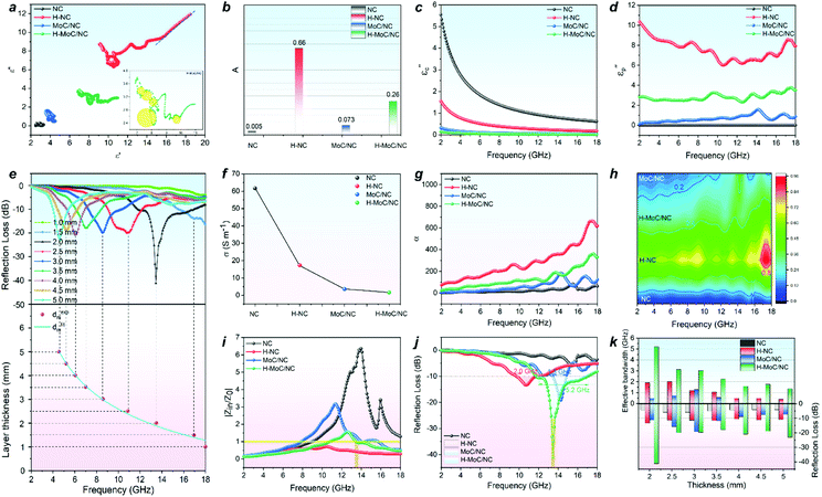
The electromagnetic wave absorbing performance was evaluated by electromagnetic parameters of the samples in a paraffin wax ring with a loading amount of 15 wt%. For a nonmagnetic material system, the real part and imaginary part of permittivity (ε′ and ε′′) in the formula of relative complex permittivity (εr = ε′ − jε′′) represent the storage and the dissipation capacities of the electro-magnetic wave, respectively, while the tan δε (tan δε = ε′′/ε′) acts the index for the dielectric loss. The dielectric loss combines both effects of conduction loss and polarization loss. The general trends of ε′, ε′′ and tan δε in Fig. S14† exhibited the higher permittivity parameters for hollow structural H-MoC/NC and H-NC than those for solid MoC/NC and NC, which was attributed to the enhanced interfacial polarization loss from the hollow structure. As we know, the polarization loss includes interfacial polarization and dipole polarization. For solid MoC/NC and NC, the higher permittivity parameters for MoC/NC than NC were mainly due to the dipole polarization loss. Conductive loss of the material can be expressed in the free electron formula, ε′′ ≈ σ/2πfε0. The higher ε′′ of H-NC than that of H-MoC/NC indicates the primary conductive loss in H-NC. In general, the dielectric loss of these samples are the results of synergistic effects between the conduction and polarization loss.The Cole–Cole semicircle model was used to explain the polarization relaxation process, which is expressed in eqn (S1).† In the ε′–ε′′ curves, every semicircle stands for a Debye relaxation process. The high number of the semicircles for H-MoC/NC indicated its high dipole depolarization loss and the interfacial polarization (Fig. S15†). In addition, the long line tail in the ε′–ε′′ curve of NC (Fig. 3a) also indicates its brilliant conduction loss contribution.
In order to further quantitatively evaluate the contribution of the polarization loss, the interfacial polarization was first analysed through the Debye relaxation correction formula (eqn (S2) and (S3)†). In the formula, A is defined as the interface factor that fitted from ε′ values, standing for the interface polarization (Fig. S16†). The A values of samples have been calculated in Fig. 3b. The higher A values of 0.26 and 0.66 for H-MoC/NC and H-NC were observed, confirming the dominant interfacial polarization in hollow porous materials. Moreover, the higher A value of MoC/NC (0.073) than that of NC (0.005) is observed, which is attributed to the chemical hetero-interface polarization in MoC/NC.
Furthermore, the quantitative evaluation of the polarization contribution from ε′′ values was also conducted by the Debye theory through the eqn (S4)–(S6).† First, the conductive contribution part (εc′′) of the samples (Fig. 3c) was calculated by the four-electrode resistance test results (Fig. 3f) through eqn (S4).† The conductivity sequence of NC > H-NC > H-MoC/NC > MoC/NC indicates the biggest contribution on conduction loss εc′′ for NC from 5.54 to 0.62. Then, the polarization loss (εp′′) of the samples was calculated through eqn (S5) and (S6),† which confirmed the dominant polarization effect (εp′′) in H-NC and H-MoC/NC from 10.36 to 7.93 and 2.83 to 3.49, respectively (Fig. 3d). These results indicate the dominated hetero-interfacial polarization in H-MoC/NC. As a result, the integrated permittivity of the materials reflected in the attenuation coefficient (α), which could be calculated through eqn (S7).† The higher α value of the material indicated the stronger compositive electromagnetic wave attenuation ability, combining the permeability and permittivity. In accordance with the dielectric loss (Fig. 3h), the α value (Fig. 3g) sequence of H-NC > H-MoC/NC > MoC/NC > NC was observed, which meant that H-NC possessed the strongest EW attenuation ability.
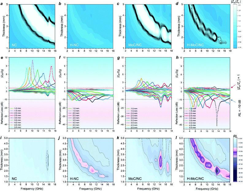
Then, the electromagnetic wave absorbing performance of the materials was evaluated by reflection loss (RL) and |Zin/Z0|, which were calculated from electromagnetic parameters through eqn (S8) and (9).† Although H-NC possesses the strongest integrated dielectric loss (Fig. 3h), the best EW absorption capacity (RLmin of 41.2 dB at 13.44 GHz) and widest effective absorption band (fe, RL <−10 dB) of 5.2 GHz (from 11.76 GHz −16.96 GHz) of H-MoC/NC were observed in Fig. 4h and i. The H-NC displayed a RLmin of −13.34 dB at 10.72 with the fe band of 2.0 GHz (Fig. 4b, j), while the MoC/NC exhibited a RLmin of −19.17 dB at 14.24 with the fe band of 1.3 GHz (Fig. 4c, k). It was concluded that excessive permittivity stood in the way of achieving high EM adsorption, and impedance matching of the materials played another crucial role.
The impedance matching of the materials could be evaluated by the normalized characteristic impedance (Z = |Zin/Z0|) based on eqn (S9).† The 2D contour map of Z values for all four materials are exhibited in Fig. 4a–d, in which the dark line (Z = 0.8–1.2) area indicates the good matching of the impedance. The excellent impedance matching of H–MoC/NC induced its high EW absorbing performance at the range of 4–18 GHz (Fig. 4d). The big white area in the 2D Z maps of MoC/NC and NC meant severe mismatches of impedance in the solid structures (Fig. 4a and c). Hollow structural H-NC greatly decreased the Z value, but not matched with the impedance (Fig. 4b). The synergetic effect from both the hollow space and hetero-interfaces of H-MoC/NC results in the best impedance matching and EW absorption (Fig. 3i–k). The high matching of theoretical and experimental dm of H-MoC/NC (Fig. 3e) was verified through the quarter-wavelength formula (eqn S10).† As compared in Table S1 and Fig. S9,† H-MoC/NC displayed remarkable SRL values of −275 at the thickness of 2 nm, making it one of the best Mo-based EWAM reported to date.
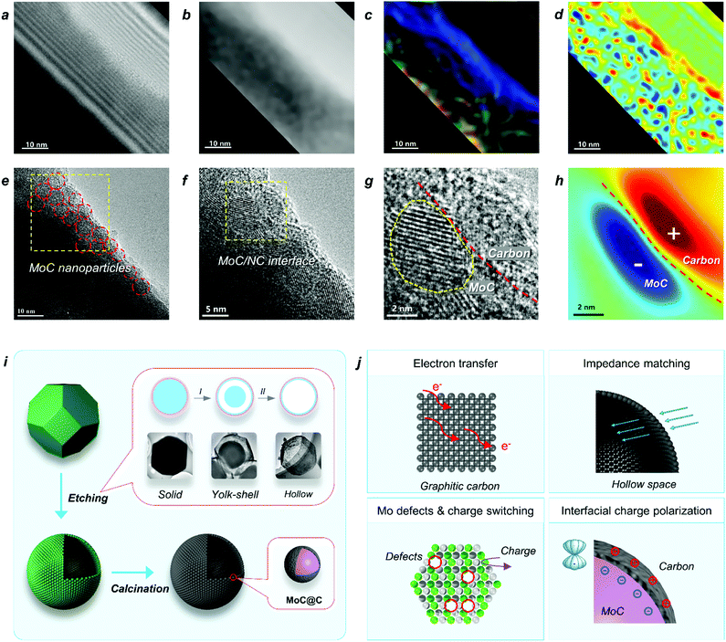
Based on the above studies, we can conclude that the polarization on MoC/NC hetero-interfaces in the hollow shell enhanced both the dielectric loss and impedance matching. In studies, scientists have successfully calculated the contribution of interfacial polarization in permittivity attenuation and proved its mechanism by spectroscopy characterizations; however, it has not been explained from an atomic level. In this study, the HR-TEM (Fig. 5e) and a hologram (Fig. 5a) were employed for investigating the mechanism of the interfacial polarization in H-MoC/NC. The tube area on the TEM image in Fig. 5a was the place that the beam lighted, which was the effective observing area. In the electric field distribution diagram (Fig. 5c), colour represents direction and brightness represents intensity, and the colour disk is shown in Fig. S20.† In the charge density map (Fig. 5d), red represents positive charge, blue represents negative charge, and the lightness colour represents relative density. The homogeneous distribution of the MoC is shown in Fig. 5e, and the high density of nanoscale MoC/NC interfacial polarization (2–3 nm) in the charge density map, as shown in Fig. 5d, which highly agreed with the distribution of MoC nanoparticles in the carbon matrix. The hetero-interface between the MoC particle and carbon matric is clearly shown in Fig. 5g, while the corresponding charge density map (Fig. 5h) indicated the charge distribution along the hetero-interface. The Mo defects in MoC accelerated the charge transfer, resulting in the accumulation of the negative charge on the surface of MoC particles. Moreover, the positive shifts of the carbon atoms induced the positive charge on the surface of carbon matrix, generating the charge polarization between the MoC(−)/carbon(+) interfaces (Fig. 5h). It is the first time to observe and explain the interfacial polarization at a nano-meter scale.
Synthetic and electromagnetic wave absorbing mechanism
The mechanism of the two-step synthetic route for constructing a hollow MoC/N-doped carbon sphere with hetero-interfaces is displayed in Fig. 5i, including an acid etching and a high-temperature calcination process. First, through a diffusion/dissolution process HZIF-ZnMo polyhedron was in situ transformed into a HZIF-ZnMo hollow sphere. During the etching process, the yolk-shell intermediate HZIF-ZnMo was observed through the TEM images. Second, in the high-temperature calcination process, owing to the superior thermal stability and orderly arranged MoO4 units in the crystalline structure of HZIF-ZnMo, a well-maintained MoC/NC hollow sphere was obtained. In the hollow shell, abundant MoC nanoparticles were embedded into the N-doped carbon matrix, affording nanometer level of hetero-interfaces.The EW attenuation mechanism of H-MoC/NC is illustrated in Fig. 5j, which mainly included four aspects: (i) the fast electron transfer on graphite carbon contributed to the conductive loss, resulting in the enhanced dielectric loss; (ii) the hollow space synergetic worked with dielectric loss, making H-MoC/NC to obtain the best impedance matching; (iii) the Mo defects in the MoC induced the charge switching of adjacent Mo atoms, enhancing the dipole polarization; (iv) Mo defects induced the accumulation of the negative charge on the surface of MoC, which strengthened the polarization on the MoC(−)/carbon(+) interface.
Conclusions
In summary, we subtly constructed a hollow MoC-incorporated N-doped carbon sphere (H-MoC/NC) with a nanoscale MoC(−)/NC(+) interface, as an EWAM, displaying a synergistic effect of conductive loss, dipole polarization loss, interfacial polarization and impedance matching. Through the accurate structural characterization and theoretical calculation, the dominate contribution of interfacial polarization on hetero-interfaces among MoC nanoparticles and N-doped carbon in the hollow shell was clarified. The Mo defects in the MoC lattice were observed, which directly enhanced the MoC(−)/carbon(+) interfacial polarization through charge switching and charge accumulation. To the best of our knowledge, it is the first time to observe and understand the interfacial polarization at the atomic level. Our findings open a new era, guiding the design and synthesis of highly efficient non-magnetic carbon-based EWAMs.Author contributions
W. H. H. conceived the idea. W. M. G. and L. X. Z. carried out the materials synthesis. W. M. G., S. W. Z. and H. B. Z. conducted the materials characterizations and data analysis. W. H. H. performed the EW absorbing performance and calculations. K. P. and R. C. C. conducted the characterization and analysis for the holography images and charge density maps. W. H. H. wrote the manuscript. All authors read and commented on the manuscript.Conflicts of interest
There are no conflicts to declare.Acknowledgements
This work was financially supported by the National Natural Science Foundation of China (22001156), the open Foundation of State Key Laboratory of Structural Chemistry (20180024), the open Foundation of Key Laboratory of Coal to Ethylene Glycol and Its Related Technology (201801) and King Abdullah University of Science and Technology.Notes and references
- D.-X. Yan, H. Pang, B. Li, R. Vajtai, L. Xu, P.-G. Ren, J.-H. Wang and Z.-M. Li, Adv. Funct. Mater., 2015, 25, 559–566 CrossRef CAS.
- B. Quan, W. Shi, S. J. H. Ong, X. Lu, P. L. Wang, G. Ji, Y. Guo, L. Zheng and Z. J. Xu, Adv. Funct. Mater., 2019, 29, 1901236 CrossRef.
- Y. Wan, X. Wang, X. Li, S. Liao, Z. Lin, Y. Hu, T. Zhao, X. Zeng, C. Li, S. Yu, P. Zhu, R. Sun and C. Wong, ACS Nano, 2020, 14, 14134–14145 CrossRef CAS PubMed.
- R. Tan, J. Zhou, Z. Yao, B. Wei and Z. Li, Ceram. Int., 2021, 47, 2077–2085 CrossRef CAS.
- F. Ghanbari, S. Moradi Dehaghi and H. Mahdavi, J. Coat. Technol. Res., 2020, 17, 815–826 CrossRef CAS.
- Y. Lian, B. Han, D. Liu, Y. Wang, H. Zhao, P. Xu, X. Han and Y. Du, Nano-Micro Lett., 2020, 12, 153 CrossRef CAS PubMed.
- P. Liu, S. Gao, W. Huang, J. Ren, D. Yu and W. He, Carbon, 2020, 159, 83–93 CrossRef CAS.
- H. Lv, Z. Yang, P. L. Wang, G. Ji, J. Song, L. Zheng, H. Zeng and Z. J. Xu, Adv. Mater., 2018, 30, 1706343 CrossRef PubMed.
- C. Wu, Z. Chen, M. Wang, X. Cao, Y. Zhang, P. Song, T. Zhang, X. Ye, Y. Yang, W. Gu, J. Zhou and Y. Huang, Small, 2020, 16, 2001686 CrossRef CAS PubMed.
- M. Ning, P. Jiang, W. Ding, X. Zhu, G. Tan, Q. Man, J. Li and R. Li, Adv. Funct. Mater., 2021, 31, 2011229 CrossRef CAS.
- X. Zhang, J. Zhu, P. Yin, A. Guo, A. Huang, L. Guo and G. Wang, Adv. Funct. Mater., 2018, 28, 1800761 CrossRef.
- F. Ye, Q. Song, Z. Zhang, W. Li, S. Zhang, X. Yin, Y. Zhou, H. Tao, Y. Liu, L. Cheng, L. Zhang and H. Li, Adv. Funct. Mater., 2018, 28, 1707205 CrossRef.
- G. Logesh, U. Sabu, C. Srishilan, M. Rashad, A. Joseph, K. C. J. Raju and M. Balasubramanian, Ceram. Int., 2021, 47, 22540–22549 CrossRef CAS.
- Z. Wu, K. Pei, L. Xing, X. Yu, W. You and R. Che, Adv. Funct. Mater., 2019, 29, 1901448 CrossRef.
- P. Liu, S. Gao, G. Zhang, Y. Huang, W. You and R. Che, Adv. Funct. Mater., 2021, 31, 2102812 CrossRef CAS.
- L. Wu, Y. Lu, W. Shao, H. Wei, G. Tong and W. Wu, Adv. Mater. Interfaces, 2020, 7, 2000736 CrossRef CAS.
- H. Lv, Z. Yang, B. Liu, G. Wu, Z. Lou, B. Fei and R. Wu, Nat. Commun., 2021, 12, 834 CrossRef CAS PubMed.
- J. Shu, W. Cao and M. Cao, Adv. Funct. Mater., 2021, 31, 2100470 CrossRef CAS.
- X. Wang, W. Cao, M. Cao and J. Yuan, Adv. Mater., 2020, 32, 2002112 CrossRef CAS PubMed.
- R. Fan, B. Xiong, R. Peng and M. Wang, Adv. Mater., 2020, 32, 1904646 CAS.
- Y. Guo, D. Wang, T. Bai, H. Liu, Y. Zheng, C. Liu and C. Shen, Adv. Compos. Hybrid Mater., 2021, 4, 602–613 CrossRef CAS.
- L. Wang, X. Yu, X. Li, J. Zhang, M. Wang and R. Che, Chem. Eng. J., 2020, 383, 123099 CrossRef CAS.
- Q. Wu, B. Wang, Y. Fu, Z. Zhang, P. Yan and T. Liu, Chem. Eng. J., 2021, 410, 128378 CrossRef CAS.
- G. Liu, X. Liu, Z. Song, X. Sun, Y. Li, J. Shui and R. Yu, Chem. Eng. J., 2021, 417, 128093 CrossRef CAS.
- X. Lu, D. Zhu, X. Li, M. Li, Q. Chen and Y. Qing, Adv. Compos. Hybrid Mater., 2021, 4, 946–956 CrossRef CAS.
- M. Zeng, Q. Cao, J. Liu, B. Guo, X. Hao, Q. Liu, X. Liu, X. Sun, X. Zhang and R. Yu, ACS Appl. Mater. Interfaces, 2020, 12, 1222–1231 CrossRef CAS PubMed.
- J. Xiong, Z. Xiang, B. Deng, M. Wu, L. Yu, Z. Liu, E. Cui, F. Pan, R. Liu and W. Lu, Appl. Surf. Sci., 2020, 513, 145778 CrossRef CAS.
- R. Peymanfar and F. Fazlalizadeh, Chem. Eng. J., 2020, 402, 126089 CrossRef CAS.
- Q. Liu, X. Liu, H. Feng, H. Shui and R. Yu, Chem. Eng. J., 2017, 314, 320–327 CrossRef CAS.
- X. Xu, G. Wang, G. Wan, S. Shi, C. Hao, Y. Tang and G. Wang, Chem. Eng. J., 2020, 382, 122980 CrossRef CAS.
- X. Li, X. Yin, C. Song, M. Han, H. Xu, W. Duan, L. Cheng and L. Zhang, Adv. Funct. Mater., 2018, 28, 1803938 CrossRef.
- X. Liang, Z. Man, B. Quan, J. Zheng, W. Gu, Z. Zhang and G. Ji, Nano-Micro Lett., 2020, 12, 102 CrossRef CAS PubMed.
- L. Wang, M. Huang, X. Yu, W. You, J. Zhang, X. Liu, M. Wang and R. Che, Nano-Micro Lett., 2020, 12, 150 CrossRef CAS PubMed.
- F. Pan, Z. Liu, B. Deng, Y. Dong, X. Zhu, C. Huang and W. Lu, Nano-Micro Lett., 2021, 13, 43 CrossRef PubMed.
- Q. Song, F. Ye, X. Yin, W. Li, H. Li, Y. Liu, K. Li, K. Xie, X. Li, Q. Fu, L. Cheng, L. Zhang and B. Wei, Adv. Mater., 2017, 29, 1701583 CrossRef PubMed.
- W.-L. Song, Y.-J. Zhang, K.-L. Zhang, K. Wang, L. Zhang, L.-L. Chen, Y. Huang, M. Chen, H. Lei, H. Chen and D. Fang, Adv Sci, 2020, 7, 1902162 CrossRef CAS PubMed.
- X. Gao, X. Wu and J. Qiu, Adv. Electron. Mater., 2018, 4, 1700565 CrossRef.
- N. L. Rosi, Chem. Res. Chin. Univ., 2021, 37, 187–188 CrossRef CAS.
- B. Wen, H. Yang, Y. Lin, L. Ma, Y. Qiu, F. Hu and Y. Zheng, J. Mater. Chem. A, 2021, 9, 3567–3575 RSC.
- J. Xu, R. Li, S. Ji, B. Zhao, T. Cui, X. Tan, G. Gou, J. Jian, H. Xu, Y. Qiao, Y. Yang, S. Zhang and T. Ren, ACS Nano, 2021, 15, 8907–8918 CrossRef CAS PubMed.
- L. Hou, Y. Shi, S. Zhu, M. Rehan, G. Pang, X. Zhang and C. Yuan, J. Mater. Chem. A, 2017, 5, 133–144 RSC.
- W. H. Huang, X. M. Li, X. F. Yang, H. B. Zhang, F. Wang and J. Zhang, Chem. Commun., 2021, 57, 4847–4850 RSC.
- J. Wang, L. Liu, S. Jiao, K. Ma, J. Lv and J. Yang, Adv. Funct. Mater., 2020, 30, 2002595 CrossRef CAS.
- F. Ran, X. Yang, X. Xu, S. Li, Y. Liu and L. Shao, Chem. Eng. J., 2021, 412, 128673 CrossRef CAS.
- Y. Zhu, X. Jiang, L. Lin, S. Wang and C. Chen, Chem. Res. Chin. Univ., 2020, 36, 1032–1038 CrossRef CAS.
- X. Wang, L. Zhuang, Y. Jia, L. Zhang, Q. Yang, W. Xu, D. Yang, X. Yan, L. Zhang, Z. Zhu, C. L. Brown, P. Yuan and X. Yao, Chem. Res. Chin. Univ., 2020, 36, 479–487 CrossRef CAS.
- Z. Zeng, T. Wu, D. Han, Q. Ren, G. Siqueira and G. Nyström, ACS Nano, 2020, 14, 2927–2938 CrossRef CAS PubMed.
- F. Wang, Z. S. Liu, H. Yang, Y. X. Tan and J. Zhang, Angew. Chem., Int. Ed., 2011, 50, 450–453 CrossRef CAS PubMed.
- Y. Li, R. Zhang, W. Zhou, X. Wu, H. Zhang and J. Zhang, ACS Nano, 2019, 13, 5533–5540 CrossRef CAS PubMed.
- D. Mao, J. Wan, J. Wang and D. Wang, Adv. Mater., 2019, 31, 1802874 CrossRef PubMed.
- L. Wang, J. Wan, Y. Zhao, N. Yang and D. Wang, J. Am. Chem. Soc., 2019, 141, 2238–2241 CrossRef CAS PubMed.
- Y. T. Xu, Z. M. Ye, J. W. Ye, L. M. Cao, R. K. Huang, J. X. Wu, D. D. Zhou, X. F. Zhang, C. T. He, J. P. Zhang and X. M. Chen, Angew. Chem., Int. Ed., 2019, 58, 139–143 CrossRef CAS PubMed.
- W. Huang, Q. Li, D. Yu, Y. Tang, D. Lin, F. Wang and J. Zhang, Inorg. Chem., 2021, 60, 3074–3081 CrossRef CAS PubMed.
Footnote |
| † Electronic supplementary information (ESI) available. See DOI: 10.1039/d1ta09357f |
| This journal is © The Royal Society of Chemistry 2022 |

