Atomic Co–N4 and Co nanoparticles confined in COF@ZIF-67 derived core–shell carbon frameworks: bifunctional non-precious metal catalysts toward the ORR and HER†
Minghao
Liu
ab,
Qing
Xu
 *ac,
Qiyang
Miao
ad,
Shuai
Yang
e,
Ping
Wu
ac,
Guojuan
Liu
ac,
Jun
He
 b,
Chengbing
Yu
*d and
Gaofeng
Zeng
 *ac
*ac
aCAS Key Laboratory of Low-Carbon Conversion Science and Engineering, Shanghai Advanced Research Institute, Chinese Academy of Sciences, Shanghai 201210, China. E-mail: xuqing@sari.ac.cn; zenggf@sari.ac.cn
bDepartment of Chemical and Environmental Engineering, University of Nottingham Ningbo China, Ningbo 315100, China
cSchool of Chemical Engineering, University of Chinese Academy of Sciences, 19A Yuquan Road, Beijing 100049, China
dSchool of Materials Science and Engineering, Shanghai University, Shanghai 200444, China. E-mail: ycb101@shu.edu.cn
eShanghai Synchrotron Radiation Facility, Shanghai Advanced Research Institute, Chinese Academy of Sciences, Shanghai 201210, China
First published on 24th November 2021
Abstract
Constructing heterostructures of covalent organic frameworks (COFs) and metal organic frameworks (MOFs) has gained great attention for various applications due to their well-defined skeletons, ordered porosity and designable functions. Herein, the core–shell structured carbon frameworks, which contain high density active sites of uniform Co nanoparticles and atomic Co–N4, were realized by direct pyrolysis of TP-BPY-COF@ZIF-67. The thin COF-shell not only prevented the collapse and aggregation of ZIF-67 but also promoted the formation of mesopores for mass transport, and enhanced the graphitization degree for conductivity. The resultant COF@ZIF800 exhibited bifunctional catalytic performance for the ORR and HER, in which the half-wave potential for ORR was 0.85 V in 0.1 M KOH and the over-potential for HER was 0.16 V at 10 mA cm−2 in 1 M KOH were achieved. This work sheds light on exploring COFs and MOFs in electrochemical energy storage and conversion systems.
Introduction
The oxygen reduction reaction (ORR) and hydrogen evolution reaction (HER) play vital roles in electrochemical energy storage and conversion devices, including metal-air batteries, fuel cells, and water splitting.1 Up to now, Pt-based compounds were mostly employed as catalysts for the ORR and HER due to their high activity.2 However, their high costs and weak durability impede their further applications. Thus, developing robust and highly active catalysts is highly desirable for the ORR and HER.3 Recently, non-noble metal catalysts have been getting more attention owing to their affordable cost.4 Till now, there have been two classes of hosts used to support metal atoms or nanoparticles, carbon-based materials including carbon nanotubes, graphene, and porous carbons, and metal-containing compounds such as oxides, dichalcogenides, carbides, and nitrides.5 Different from the metal-containing support, carbon-based materials not only provide anchoring sites for single metal atoms and offer good electrical conductance with the graphitic skeletons, but also manipulate the charge density and electronic structure of the metal atoms and nanoparticles.6Covalent organic frameworks (COFs) possess a periodic atomic distribution, well-defined skeletons, and ordered porous channels, and have displayed versatile applications such as gas/molecular capture and separation, sensor, heterogeneous catalysis, and ionic conduction.7 With controlling the active sites of COFs, interestingly, it permits COFs to be an ideal platform for catalyzing the ORR, oxygen evolution reaction and CO2 reduction reaction.8 For example, Cao et al. demonstrated conductive MOFs to synthesize CO by the CO2 electroreduction reaction (CO2RR).9 Additionally, Jiang and his coworkers developed conductive COFs for CO synthesis from CO2.10 However, the poor conductivity of COFs limits their electro-catalytic behaviors. To improve the conductivity, pyrolysis of COFs into functional carbon is a simple and efficient strategy.11 Nevertheless, the direct pyrolysis of COFs always made carbons with aggregated skeletons and collapsed pores.6 To obtain carbons with high surface areas, COF-5 was mixed with ZnCl2, and the molten salts assisted in preparing boron-doped carbon with hierarchical pores, which showed enhanced hydrogen storage capacity and capacitive storage ability.14 Jiang and his co-workers grew COFs on conjugated polymers to obtain thickness-control core shell micro-porous carbons, which achieved higher capacitance than that prepared by direct carbonization of COFs.13 In addition, Jiang et al. demonstrated metal-free bifunctional carbon for both the ORR and OER by adopting phytic acid as a template, which not only realizes the doping of phosphorus into the COF-derived carbons but also facilitates the formation of porous structures.12 Wang et al. constructed MnS trapped in hybrids of COF and MOF derived carbon for the application of lithium ion batteries.15 Recently, our previous work presented the synthesis of PtZn alloy nanoparticles and single-dispersed Zn atoms on COF@ZIF-8 derived carbon for high performance ORR applications.16 However, how to precisely synthesize COF-derived carbons for bifunctional catalysts for the ORR and HER is still under explored.
Herein, we have designed and synthesized Co nanoparticles and atomic Co–N4 embedded carbons for catalyzing the ORR and HER from a core–shell hybrid of COFs and ZIF-67. The corresponding carbon possessed abundant active sites, multi-level porosity, and high graphitization degree. The optimized catalyst showed superior activity and stability to those of the commercial Pt/C catalyst for the ORR in 0.1 M KOH solution. Additionally, the catalyst enables catalyzing the HER with a positive onset potential compared to other Co-based catalysts in 1 M KOH.
Results and conclusions
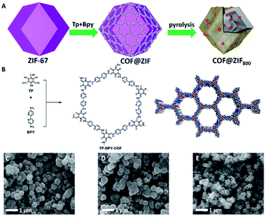
As illustrated in Fig. 1A, the preparation of COF@ZIF800 involves creating ZIF-67 nanocrystals, in situ encapsulating ZIF-67 crystals with a TP-BPY-COF thin layer (COF@ZIF) and controlled-pyrolysis of COF@ZIF in an inert atmosphere.17 The scanning electron microscopy (SEM) images showed that the as-prepared ZIF-67 crystals presented a dodecahedron morphology with a uniform particle size of ∼350 nm and smooth surface (Fig. 1C and S1†). After TP-BPY-COF coating, the COF@ZIF particles were well isolated without visible aggregations and retained the rhombic dodecahedral morphology and the similar particle size to that of ZIF-67 precursors (Fig. 1D and S2†). This suggests that the TP-BPY-COF layer is thin. In addition, the Fourier transform infrared (FT-IR) spectra showed that COF@ZIF exhibited a new vibration band at 1578 cm−1, ascribed to the C![[double bond, length as m-dash]](https://www.rsc.org/images/entities/char_e001.gif) N linkages, suggesting the successful formation of the TP-BPY-COF (Fig. S3†). At the same time, all bands of ZIF-67 can also be clearly identified from the spectrum of COF@ZIF (Fig. S3†).
N linkages, suggesting the successful formation of the TP-BPY-COF (Fig. S3†). At the same time, all bands of ZIF-67 can also be clearly identified from the spectrum of COF@ZIF (Fig. S3†).
This revealed that the framework of ZIF-67 was intact during the coating of the COF layer. Although the COF@ZIF800 particles shrank in comparison to their precursors, the framework morphology was well maintained without collapse. This indicated that the organic components of COF@ZIF were lost while the skeleton was well maintained during the pyrolysis (Fig. 1E).
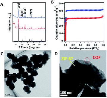
With coating the COF on the surface of ZIF-67, all the peaks from ZIF-67 were well retained. The simulated PXRD pattern of ZIF-67 (Fig. 2A, black curve), revealed the peaks at 7.44°, 10.56°, 12.92° and 18.13° correspond to the (011), (002), (112) and (222) facets (Fig. 2A, blue curve), respectively. In addition, a new peak at 3.6° was clearly identified, which corresponds to the (100) facet of the COF (Fig. 2A, red curve). The interface interaction between the shell layer and the core particle was proved by X-ray photoelectron spectroscopy (XPS) measurements (Fig. S4†). The binding energy of the Co peak decreased from 781 eV for ZIF-67 to 780 eV for COF@ZIF, suggesting the interaction between the Co ions and bipyridine units. In addition, the Co content on the ZIF-67 surface was 14.7 wt%, close to the elemental composition of ZIF-67, while COF@ZIF had 1.0 wt% Co, confirming that the TP-BPY-COF thin layer was successfully formed. The pore structure of ZIF-67 and COF@ZIF was investigated using N2 sorption isotherms at 77 K (Fig. 2B). Both samples showed a steep increase in the N2 adsorption–desorption isotherms at P/P0 around 0, which was due to the filling of micropores.18 The same slope in this region also indicated that both samples had a similar micro-pore size. This further suggests that the structure of ZIF-67 cores is unchanged, and the outer layer of the TP-BPY-COF is thin. The Brunauer–Emmett–Teller (BET) specific surface areas of ZIF-67 and COF@ZIF were 1439 and 1051 m2 g−1, with corresponding pore volumes of 0.65 and 0.51 cm3 g−1, respectively. Similar to the SEM observations (Fig. 1D and S2†), the transmission electron microscopy (TEM) image of COF@ZIF showed well separated nanocrystals with a rhombic dodecahedral structure (Fig. 2C). With higher resolution, it is easy to observe that the COF@ZIF nanocrystals were composed of the regular crystal core and the outer shell with a thickness of ∼30 nm (Fig. 2D and S5†). Thermal gravimetric analysis (TGA) of ZIF-67 and COF@ZIF samples was conducted under N2. ZIF-67 showed obvious decomposition at 500 °C, while the starting decomposition temperature for COF@ZIF was about 550 °C (Fig. S6†). It is reasonable that the interactions between the ZIF-67 core and TP-BPY-COF shell increase the thermal stability of COF@ZIF.
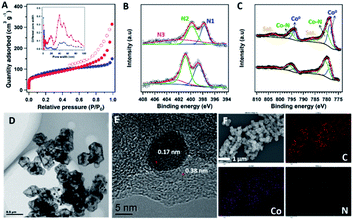
To investigate the effects of the core–shell structure on the properties of the pyrolysis products, both ZIF-67 and COF@ZIF samples were heated at 800 °C under N2 for 1 h to prepare ZIF800 and COF@ZIF800, respectively. The PXRD patterns revealed that the peaks at 26.5°, 44.1°, 52.5° and 76.8° were ascribed to the graphitic carbon (002), (111), (200) and (220) facets of Co (Fig. S7†), respectively. This indicates that the organic groups of the precursors were decomposed, and the crystalline structure of ZIF-67 was totally changed, leaving the inorganic graphitic-skeletons and metallic particles. The N2 sorption curve of COF@ZIF800 exhibited type-IV isotherms with an obviously bigger hysteresis loop than that of ZIF800 in the region 0.5 < P/P0 < 1.0, suggesting enhanced mesopores in COF@ZIF800 (Fig. 3A). Correspondingly, COF@ZIF800 exhibited a total pore volume of 0.48 cm3 g−1 and a mesopore volume of 0.26 cm3 g−1 (accounting pore size > 20 nm), which were much larger than those of ZIF800 (total- and meso-pore volumes of 0.23 and 0.04 cm3 g−1, respectively) (Fig. 3A, inset). With the increase of mesopores, the BET specific surface area of COF@ZIF800 slightly decreased from 303 m2 g−1 for ZIF800 to 244 m2 g−1. Therefore, the core–shell COF@ZIF structure is helpful to form mesopores in the catalyst, which benefits mass transport in the electrochemical processes.
The Raman spectra of ZIF800 and COF@ZIF800 provided the characteristic signals of graphitic carbon, which contained a G band at 1590 cm−1, arising from the first-order scattering of sp2 carbon atoms in a 2D hexagonal lattice, and a D band at 1354 cm−1, ascribed to the vibrations of carbon atoms' in plane terminations of disordered graphite (Fig. S8†).19 The intensity ratio of the D and G band (ID/IG), which was sensitive to the level of disorder and defects on the carbon backbone, decreased from 1.07 of ZIF800 to 0.96 of COF@ZIF800. It indicates that the COF@ZIF structure is helpful to form more ordered graphitic carbon during pyrolysis.
The XPS measurements unveiled C, Co, N, and O elements on the sample surface. ZIF800 contained 9.51 wt% Co and 5.22 wt% N while COF@ZIF800 had 5.98 wt% Co and 4.41 wt% N on the surface (Fig. S9†). As no Co existed in the precursor of the TP-BPY-COF, the enrichment of Co on the surface of COF@ZIF800 revealed the migration of Co from the core to the surface during pyrolysis. The high-resolution N 1s spectrum of ZIF800 can be deconvoluted into three peaks centred at ∼397.7, ∼399.8, and ∼402.0 eV, which can be ascribed to pyridinic N (N1, weighing 27.7%), pyrrolic N (N2, 36.1%), and graphitic N (N3, 36.2%), respectively (Fig. 3B). Similarly, the XPS N 1s spectrum of COF@ZIF800 also showed these types of nitrogen. However, the binding energies of these peaks were left-shifted by ∼0.7 eV. This suggests that the main element Co contributes different interaction strengths with nitrogen in ZIF800 and COF@ZIF800. In addition, the relative content of pyridinic N in COF@ZIF800 increased to 34.5% (Fig. 3C). It has been reported that the carbon atoms next to pyridinic N were active sites for catalyzing the ORR.20 Therefore, the increased ratio of pyridinic N results in an enhanced activity of COF@ZIF800 in the electrochemical reaction. The Co 2p spectra exhibited two prominent peaks of Co 2p1/2 and Co 2p3/2, located at ∼795.6 and ∼779.8 eV, respectively (Fig. 3C). The deconvoluted peaks at 778.7 and 780.5 eV were assigned to Co (0) and Co–N, respectively, in which the Co–N content in COF@ZIF800 significantly increased from 50.5% of ZIF800 to 55.2%. The COF-shell binding to Co2+ promoted the formation of Co–N in the pyrolysis process. This confirms that the Co element provides more interactions with N in COF@ZIF800, in line with the observations from the N 1s spectra.
The morphology and structure of ZIF800 and COF@ZIF800 were further investigated by SEM and TEM. The SEM images showed that the ZIF800 samples had lost the regular crystal structure of ZIF-67, resulting in obvious collapse and aggregation (Fig. S10†). This was further proved by TEM observations, which displayed the unordered broken fragments with 15–50 nm scattering particles (Fig. S11†). In contrast, both SEM and TEM images showed that the COF@ZIF800 particles have a dodecahedral morphology similar to that of COF@ZIF, without collapse and aggregation (Fig. S12 and S13†). Moreover, the TEM image of a single COF@ZIF800 particle showed a perfect core–shell structure, being composed of a ∼40 nm thick regular shell and the shrunk core (Fig. 3D). The Co nanoparticles with 5–10 nm size were uniformly strewn on the surface of the ZIF800 core as well as the region of the shell, confirming the migration of the Co element from the ZIF-67 core to the TP-BPY-COF shell during pyrolysis. This indicates that the pyrolysis product of the TP-BPY-COF has a stronger skeleton than that of ionic bonded ZIF-67, which not only suppresses the collapse of the COF@ZIF structure but also avoids the agglomeration and growth of Co particles. The high-resolution TEM image of COF@ZIF800 showed that the ordered microstructure had interplanar spacings of 0.17 and 0.38 nm, assigned to Co (200) and nitrogen-doped graphite (002), respectively, which was well consistent with the XRD results (Fig. 3E). As reported, the ordered graphitic carbon encapsulated metallic nanoparticles would enhance not only the anchoring force but also the stability in reactions.21 In addition, graphite-confined metal particles (e.g., Pt) exhibited superior activities for the electrocatalysis of water oxidation because the electrons of metal atoms can penetrate through the graphene shell to promote the catalytic reaction.22 The energy dispersive X-ray spectroscopy (EDX) mapping images confirmed that all the C, N and Co elements were uniformly distributed in the carbon matrix (Fig. 3F and S14†).
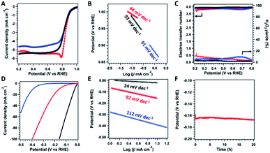
The electrochemical catalytic performance of catalysts was initially evaluated by cyclic voltammetry (CV) in O2-saturated or N2-saturated 0.1 M KOH aqueous solution at a scan rate of 50 mV s−1 (Fig. S15†). The CV curves show obvious peaks for both ZIF800 and COF@ZIF800 only under an O2 atmosphere rather than N2, suggesting their catalytic activity for oxygen conversion. In addition, the peak positions for ZIF800 and COF@ZIF800 were 0.71 and 0.75 V, respectively, indicating that COF@ZIF800 possessed higher activity than ZIF800. The linear sweep voltammetry (LSV) curves were obtained by the rotating disc electrode (RDE) measurement at 1600 rpm in O2-saturated KOH solution (Fig. 4A). For comparison, the commercial Pt/C catalyst was employed as a control. The onset potential (E0) and half-wave potential (E1/2) of Pt/C were 0.92 and 0.81 V, respectively. The E0 and E1/2 of ZIF800 were 0.96 and 0.81 V, which were close to those of Pt/C. However, the limited current density was 4.6 mA cm−2, lower than that of Pt/C (5.5 mA cm−2). Notably, COF@ZIF800 displayed higher activity than Pt/C. And the E0 and E1/2 of COF@ZIF800 were 0.99 and 0.85 V, which were 70 and 40 mV more positive than those of Pt/C, respectively. The corresponding Tafel slope of COF@ZIF800 was 44 mV dec−1, remarkably lower than that of Pt/C (93 mV dec−1) and ZIF800 (91 mV dec−1), indicating the favorable kinetic behavior (Fig. 4B). The E0, E1/2 and Tafel slope of COF@ZIF800 exceeded most reported Co-based catalysts (Table S1†). With different scan rates in RDE measurements, moreover, the kinetic current densities of COF@ZIF800 at 0.90, 0.85 and 0.80 V were 0.96, 3.01 and 10.56 mA cm−2, respectively, which are much higher than those of Pt/C (Fig. S16 and Table S2†). The selectivity of the catalysts was then explored by the rotating ring-disk electrode (RRDE) measurements. Both catalysts catalyzed the ORR in the 4e− pathway. The electron transfer number for COF@ZIF800 fluctuated from 3.79 to 3.94 in the potential range of 0.2 to 0.8 V, suggesting their 4e− pathway towards the ORR (Fig. 4C). Correspondingly, the H2O2 yields were calculated in the range of 2.4% to 10.0%, which suggests the high selectivity for O2 to H2O. Similarly, ZIF800 also shows the 4e− pathway for the ORR with high selectivity. In addition, COF@ZIF800 also displayed excellent long-term stability and chemical stability because the chronopotentiometry (i–t) measurement revealed that the current density was 100% of the initial value after 20 hours (Fig. S17†).
The HER performance of catalysts was tested by LSV in 1 M KOH electrolyte. As shown in Fig. 4D, the overpotential of COF@ZIF800 at a current density of 10 mA cm−2 was 159 mV, and the overpotential was positive than that of ZIF800 (388 mV). Although the Tafel slope of COF@ZIF800 (92 mV dec−1) was higher than that of Pt/C (24 mV dec−1), it displayed better kinetic activity than ZIF800 (112 mV dec−1, Fig. 4E). The over potential and Tafel slope of COF@ZIF800 exceeded most reported Co-based catalysts (Table S3†). In addition, the chronoamperometry (V–t) measurement of COF@ZIF800 at a constant current density of 10 mA cm−2 showed that such electrocatalysts maintain their potential for 20 h, confirming the excellent stability (Fig. 4F).
To investigate the different conductive behaviors of ZIF800 and COF@ZIF800, alternating-current impedance spectroscopy was used to study the mass and electron transport of the catalysts. Fig. S18 and S19† show the Nyquist plots consisting of a high-to-medium-frequency depressed semicircle linked with a low-frequency sloping line in 0.1 M KOH solution. The semicircle in the high frequency region is associated with the internal resistance, while the medium-frequency semicircle is related to the charge transfer resistance (Rct). The Rct of COF@ZIF800 was 42.2 Ω, which was lower than that of ZIF800 (83.2 Ω), suggesting a higher conductivity. Moreover, COF@ZIF800 had a higher slope than ZIF800, which suggests the fast ionic diffusion. The fast mass and electron transport of COF@ZIF800 are attributed its unique porosity and high graphitization degree.
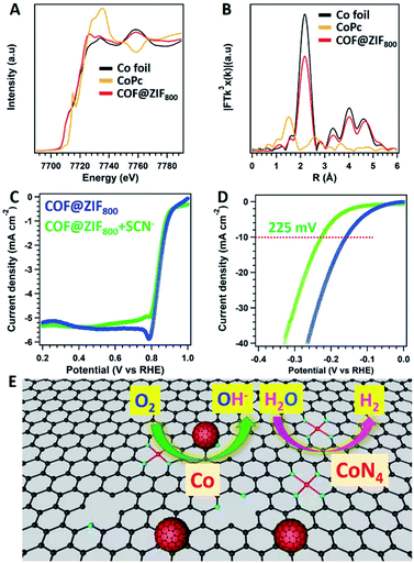
To further clarify the active sites for COF@ZIF800 in the electrochemical process, the X-ray absorption fine structure (XAFS) measurement was carried out. The Co of COF@ZIF800 displayed different near-edge structures to the corresponding oxidation states (CoPc) and simple substances (Co foil) (Fig. 5A). The peak position of Co in R-space was 2.17 Å, which was same as that of Co–Co coordination (Fig. 5B). And the fitting of the obtained EXAFS data revealed that Co–N4 and Co–Co were the dominant coordination mode of Co atoms (Fig. S20 and Table S4†). The atomic state of Co was further verified using high-angle annular dark-field scanning transmission electron microscopy (HAADF-STEM) images. The bright dots were clearly identified, which were from the Co atoms (Fig. S21†). Differently, the EXAFS data showed that there were no Co–N bonds in ZIF800 (Fig. S22†). Thus, COF@ZIF800 contains both atomic Co–N4 and Co nanoparticles.
The active sites in the catalysts were explicated by the SCN− deactivated experiments. With the addition of SCN−, COF@ZIF800 towards the ORR displayed strong tolerance to SCN−. E1/2 displayed slight changes to 0.84 V, while the corresponding jlim was well retained (Fig. 5C). Thus, N-doped carbons and Co nanoparticles embedded in the carbon contributed to the major roles in the ORR. However, the over-potential of COF@ZIF800 towards the HER exhibited a negative shift to 225 mV (Fig. 5D). The lower activity for the HER contributed to the Co–N4 sites blocked with SCN−, suggesting that Co–N4 plays a vital role in the HER (Fig. 5D).23 Therefore, the atomic Co–N4 sites and Co nanoparticle sites confined in COF@ZIF-67 derived core–shell carbon frameworks play different roles in catalyzing the ORR and HER (Fig. 5E). The ORR and HER performance were dependent on the Co nanoparticles and the Co–N4 sites, respectively.
Conclusions
In summary, a core–shell bifunctional catalyst for the ORR and HER has been synthesized. The COF-shell prevents the collapse of the MOF-core in the pyrolysis process. In addition, the core–shell morphology benefits mass transport, and the COF-derived shell facilitates electron conductivity. The catalyst had Co–N4 atoms together with Co nanoparticles embedded in carbon, which enables catalyzing the ORR and HER with high activity and excellent stability. This work provides a new platform to design multifunctional catalysts from COFs.Author contributions
Q. X. conceived the idea and designed the experiments. M. L., Q. X., and Q. M. performed the experiments. S. Y. and M. L. performed the XAS experiments and analysis. Q. X. and G. Z. wrote and revised the manuscript. All the authors contributed to the data interpretation, discussion, and manuscript revision. All authors have given approval to the final version of the manuscript.Conflicts of interest
There are no conflicts to declare.Acknowledgements
Q. Xu acknowledges financial support from the Shanghai Pujiang Program (19PJ1410400) and the Natural Science Foundation of Shanghai (20ZR1464000). G. Zeng acknowledges support from the National Natural Science Foundation of China (21878322 and 22075309) and the Science and Technology Commission of Shanghai (19ZR1479200). The authors also thank the Shanghai Synchrotron Radiation Facility for XAFS measurements at beamline BL14w1.Notes and references
- (a) J. Gao and B. Liu, ACS Mater. Lett., 2020, 2, 1008–1024 CrossRef CAS; (b) R. T. Hannagan, G. Giannakakis, M. Flytzani-Stephanopoulos and E. C. H. Sykes, Chem. Rev., 2020, 120, 12044–12088 CrossRef CAS PubMed; (c) E. I. Solomon and S. S. Stahl, Chem. Rev., 2018, 118, 2299–2301 CrossRef CAS PubMed; (d) Y. Wang, H. Su, Y. He, L. Li, S. Zhu, H. Shen, P. Xie, X. Fu, G. Zhou, C. Feng, D. Zhao, F. Xiao, X. Zhu, Y. Zeng, M. Shao, S. Chen, G. Wu, J. Zeng and C. Wang, Chem. Rev., 2020, 120, 12217–12314 CrossRef CAS PubMed; (e) M. Zhou, H.-L. Wang and S. Guo, Chem. Soc. Rev., 2016, 45, 1273–1307 RSC.
- (a) Z. Jin, P. Li, Y. Meng, Z. Fang, D. Xiao and G. Yu, Nat. Catal., 2021, 4, 615–622 CrossRef CAS; (b) J. Li, A. Alsudairi, Z.-F. Ma, S. Mukerjee and Q. Jia, J. Am. Chem. Soc., 2017, 139, 1384–1387 CrossRef CAS PubMed; (c) Z. Liu, Z. Zhao, B. Peng, X. Duan and Y. Huang, J. Am. Chem. Soc., 2020, 142, 17812–17827 CrossRef CAS PubMed; (d) H. Wang, Z. N. Chen, D. Wu, M. Cao, F. Sun, H. Zhang, H. You, W. Zhuang and R. Cao, J. Am. Chem. Soc., 2021, 143, 4639–4645 CrossRef CAS PubMed.
- (a) X. Chia and M. Pumera, Nat. Catal., 2018, 1, 909–921 CrossRef CAS; (b) R. Gao and D. Yan, Adv. Energy Mater., 2020, 10, 1900954 CrossRef CAS; (c) H. Li, S. Kelly, D. Guevarra, Z. Wang, Y. Wang, J. A. Haber, M. Anand, G. T. K. K. Gunasooriya, C. S. Abraham, S. Vijay, J. M. Gregoire and J. K. Nørskov, Nat. Catal., 2021, 4, 463–468 CrossRef CAS; (d) J. A. Trindell, Z. Duan, G. Henkelman and R. M. Crooks, Chem. Rev., 2020, 120, 814–850 CrossRef CAS PubMed.
- Y. Peng, B. Lu and S. Chen, Adv. Mater., 2018, 30, 1801995 CrossRef PubMed.
- T. Sun, S. Mitchell, J. Li, P. Lyu, X. Wu, J. Pérez-Ramírez and J. Lu, Adv. Mater., 2021, 33, 2003075 CrossRef CAS PubMed.
- (a) E. J. Askins, M. R. Zoric, M. Li, Z. Luo, K. Amine and K. D. Glusac, Nat. Commun., 2021, 12, 3288 CrossRef CAS PubMed; (b) X. Y. Chia and M. Pumera, Nat. Catal., 2018, 1, 909–921 CrossRef CAS; (c) S. Dey, B. Mondal, S. Chatterjee, A. Rana, S. K. Amanullah and A. Dey, Nat. Rev. Chem., 2017, 1, 0098 CrossRef CAS; (d) A. I. Douka, Y. Xu, H. Yang, S. Zaman, Y. Yan, H. Liu, M. A. Salam and B. Y. Xia, Adv. Mater., 2020, 32, e2002170 CrossRef PubMed; (e) S. Wei, Y. Wang, W. Chen, Z. Li, W. C. Cheong, Q. Zhang, Y. Gong, L. Gu, C. Chen, D. Wang, Q. Peng and Y. Li, Chem. Sci., 2019, 11, 786–790 RSC; (f) C. He, J. Liang, Y. H. Zou, J. D. Yi, Y. B. Huang and R. Cao, Natl. Sci. Rev., 2021, nwab157 CrossRef.
- (a) C. Diercks and O. Yaghi, Science, 2017, 355, 585 CrossRef PubMed; (b) K. Geng, T. He, R. Liu, S. Dalapati, K. T. Tan, Z. Li, S. Tao, Y. Gong, Q. Jiang and D. Jiang, Chem. Rev., 2020, 120, 8814–8933 CrossRef CAS PubMed; (c) J. Guo and D. Jiang, ACS Cent. Sci., 2020, 6, 869–879 CrossRef CAS PubMed; (d) T. He, K. Geng and D. Jiang, ACS Mater. Lett., 2019, 1, 203–208 CrossRef CAS; (e) Z. Li, T. He, Y. Gong and D. Jiang, Acc. Chem. Res., 2020, 53, 1672–1685 CrossRef CAS PubMed; (f) S. Wei, F. Zhang, W. Zhang, P. Qiang, K. Yu, X. Fu, D. Wu, S. Bi and F. Zhang, J. Am. Chem. Soc., 2019, 141, 14272–14279 CrossRef CAS PubMed; (g) J. Xu, Y. He, S. Bi, M. Wang, P. Yang, D. Wu, J. Wang and F. Zhang, Angew. Chem., Int. Ed., 2019, 58, 12065–12069 CrossRef CAS PubMed; (h) J. Zhu, C. Yang, C. Lu, F. Zhang, Z. Yuan and X. Zhuang, Acc. Chem. Res., 2018, 51, 3191–3202 CrossRef CAS PubMed.
- (a) J. Guo, C. Y. Lin, Z. Xia and Z. Xiang, Angew. Chem., Int. Ed., 2018, 57, 12567–12572 CrossRef CAS PubMed; (b) D. Li, C. Li, L. Zhang, H. Li, L. Zhu, D. Yang, Q. Fang, S. Qiu and X. Yao, J. Am. Chem. Soc., 2020, 142, 8104–8108 CrossRef CAS PubMed; (c) M. Lu, J. Liu, Q. Li, M. Zhang, M. Liu, J. L. Wang, D. Q. Yuan and Y. Q. Lan, Angew. Chem., Int. Ed., 2019, 58, 12392–12397 CrossRef CAS PubMed; (d) Y. Wan, L. Wang, H. Xu, X. Wu and J. Yang, J. Am. Chem. Soc., 2020, 142, 4508–4516 CrossRef CAS PubMed; (e) Q. Wu, R. K. Xie, M. J. Mao, G. L. Chai, J. D. Yi, S.-S. Zhao, Y.-B. Huang and R. Cao, ACS Energy Lett., 2020, 5, 1005–1012 CrossRef CAS; (f) H. J. Zhu, M. Lu, Y. R. Wang, S. J. Yao, M. Zhang, Y. H. Kan, J. Liu, Y. Chen, S. L. Li and Y. Q. Lan, Nat. Commun., 2020, 11, 497 CrossRef CAS PubMed.
- (a) J. D. Yi, D. H. Si, R. Xie, Q. Yin, M. D. Zhang, Q. Wu, G. L. Chai, Y. B. Huang and R. Cao, Angew. Chem., Int. Ed., 2021, 60, 17108–17114 CrossRef CAS PubMed; (b) J.-D. Yi, R. Xie, Z.-L. Xie, G.-L. Chai, T.-F. Liu, R.-P. Chen, Y.-B. Huang and R. Cao, Angew. Chem., Int. Ed., 2020, 59, 23641–23648 CrossRef CAS PubMed.
- B. Han, X. Ding, B. Yu, H. Wu, W. Zhou, W. Liu, C. Wei, B. Chen, D. Qi, H. Wang, K. Wang, Y. Chen, B. Chen and J. Jiang, J. Am. Chem. Soc., 2021, 143, 7104–7113 CrossRef CAS PubMed.
- Q. Xu, Y. Tang, L. Zhai, Q. Chen and D. Jiang, Chem. Commun., 2017, 53, 11690–11693 RSC.
- Q. Xu, Y. Tang, X. Zhang, Y. Oshima, Q. Chen and D. Jiang, Adv. Mater., 2018, 30, e1706330 CrossRef PubMed.
- (a) X. Zhao, P. Pachfule, S. Li, T. Langenhahn, M. Ye, C. Schlesiger, S. Praetz, J. Schmidt and A. Thomas, J. Am. Chem. Soc., 2019, 141, 6623–6630 CrossRef CAS PubMed; (b) Q. Wang and D. Astruc, Chem. Rev., 2020, 120, 1438–1511 CrossRef CAS PubMed.
- Y. B. Huang, P. Pachfule, J. K. Sun and Q. Xu, J. Mater. Chem. A, 2016, 4, 4273–4279 RSC.
- W. Sun, X. Tang, Q. Yang, Y. Xu, F. Wu, S. Guo, Y. Zhang, M. Wu and Y. Wang, Adv. Mater., 2019, 31, e1903176 CrossRef PubMed.
- Y. Guo, S. Yang, Q. Xu, P. Wu, Z. Jiang and G. Zeng, J. Mater. Chem. A, 2021, 9, 13625–13630 RSC.
- S. Dutta, N. Kumari, S. Dubbu, S. W. Jang, A. Kumar, H. Ohtsu, J. Kim, S. H. Cho, M. Kawano and I. S. Lee, Angew. Chem., Int. Ed., 2020, 59, 3416–3422 CrossRef CAS PubMed.
- B. P. Biswal, S. Valligatla, M. Wang, T. Banerjee, N. A. Saad, B. M. K. Mariserla, N. Chandrasekhar, D. Becker, M. Addicoat, I. Senkovska, R. Berger, D. N. Rao, S. Kaskel and X. Feng, Angew. Chem., Int. Ed., 2019, 58, 6896–6900 CrossRef CAS PubMed.
- C. C. Hou, Y. Wang, L. Zou, M. Wang, H. Liu, Z. Liu, H. F. Wang, C. Li and Q. Xu, Adv. Mater., 2021, 33, 2101698 CrossRef CAS PubMed.
- Q. Lv, W. Si, J. He, L. Sun, C. Zhang, N. Wang, Z. Yang, X. Li, X. Wang, W. Deng, Y. Long, C. Huang and Y. Li, Nat. Commun., 2018, 9, 3376 CrossRef PubMed.
- Z. Zhu, Y. Xu, B. Qi, G. Zeng, P. Wu, G. Liu, W. Wang, F. Cui and Y. Sun, Environ. Sci.: Nano, 2017, 4, 302–306 RSC.
- (a) J. Deng, D. Deng and X. Bao, Adv. Mater., 2017, 29, 1606967 CrossRef PubMed; (b) Y. Zhang, G. Liu, L. Shi, P. Wu, G. Zeng, C. Zhang, N. Yang, S. Li and Y. Sun, iScience, 2020, 23, 101157 CrossRef CAS PubMed.
- (a) Z. Zhang, X. Zhao, S. Xi, L. Zhang, Z. Chen, Z. Zeng, M. Huang, H. Yang, B. Liu, S. J. Pennycook and P. Chen, Adv. Energy Mater., 2020, 10, 2002896 CrossRef CAS; (b) J. D. Yi, R. Xu, Q. Wu, T. Zhang, K. T. Zang, J. Luo, Y. L. Liang, Y. B. Huang and R. Cao, ACS Energy Lett., 2018, 3, 883–889 CrossRef CAS.
Footnote |
| † Electronic supplementary information (ESI) available. See DOI: 10.1039/d1ta08325b |
| This journal is © The Royal Society of Chemistry 2022 |

