
Single-atom catalysts on supported silicomolybdic acid for CO2 electroreduction: a DFT prediction†
Congcong
Zhao
a,
Xiaofang
Su
b,
Shuo
Wang
a,
Yu
Tian
c,
Likai
Yan
 *a and
Zhongmin
Su
a
*a and
Zhongmin
Su
a
aInstitute of Functional Material Chemistry, Key Laboratory of Polyoxometalate Science of Ministry of Education, Faculty of Chemistry, Northeast Normal University, Changchun 130024, P. R. China. E-mail: yanlk924@nenu.edu.cn
bHenan Normal University, Henan 453007, P. R. China
cInstitute for Interdisciplinary Quantum Information Technology, Jilin Engineering Normal University, Changchun 130052, P. R. China
First published on 14th December 2021
Abstract
The electrocatalytic CO2 reduction reaction (CO2RR) is an effective way to convert CO2 into fuels which relies on efficient catalysts due to extreme reaction activation barriers. As a new frontier in the field of catalysis, single-atom catalysts (SACs) play an important role in the CO2RR owing to their maximum atomic availability and unique properties. Herein, a new type of electrocatalyst combining transition metal (TM = Sc, Ti, V, Cr, Mn, Fe, Co, Ni, Cu, Zn, Y, Zr, Nb, Mo, Tc, Ru, Rh, Pd, Ag and Cd) with α-Keggin type Na4[SiMo12O40] (Na4SiMo12) was investigated by density functional theory (DFT) calculations. Through comprehensive screening, TM@Na4SiMo12 (TM = Sc, Ti, V, Cr, Mn, Zn, Y, Zr, Nb and Cd) have been found to exhibit robust stability. Among them, TM@Na4SiMo12 (TM = Sc, Cr, Mn, Ti, and V) have excellent catalytic activity for the CO2RR; in particular, the limiting potential (UL) for CO2RR by Cr@Na4SiMo12 is −0.23 V and the product is HCOOH. Meanwhile, Mn@Na4SiMo12 has high CO2RR selectivity and good catalytic performance (UL = −0.48 V). During the electrochemical CO2RR, polyoxometalates (POMs) act as “electron sponges”, accepting and donating electrons. It is expected that the present work will spur the development of new SACs for the CO2RR.
1. Introduction
The dramatic rise in carbon dioxide (CO2) emissions into the atmosphere has caused environmental problems such as the greenhouse effect and ocean acidification.1–3 Converting CO2 into renewable chemical fuels is considered to be one of the most efficient solutions.4–7 The electrocatalytic CO2 reduction reaction (CO2RR) has attracted extensive attention due to its mild reaction conditions, high faradaic efficiency, and environmental driving force caused by the synergistic effect with renewable energy (such as wind energy and solar energy).8 CO2 is a chemically inert molecule with linear C![[double bond, length as m-dash]](https://www.rsc.org/images/entities/char_e001.gif) O bond energy up to 803 kJ mol−1, meaning that it is difficult to activate. Therefore, the CO2RR has to rely on efficient catalysts in multi-electron transfer processes for producing the target products. Many catalysts have been explored to break the strong CO bonds, such as sulfides,9,10 phosphates,11,12 oxides,13,14etc. However, the catalytic performance of these catalysts for the CO2RR is still unsatisfactory.15 Therefore, it is of great significance to develop electrochemical CO2RR catalysts with high selectivity and high efficiency.
O bond energy up to 803 kJ mol−1, meaning that it is difficult to activate. Therefore, the CO2RR has to rely on efficient catalysts in multi-electron transfer processes for producing the target products. Many catalysts have been explored to break the strong CO bonds, such as sulfides,9,10 phosphates,11,12 oxides,13,14etc. However, the catalytic performance of these catalysts for the CO2RR is still unsatisfactory.15 Therefore, it is of great significance to develop electrochemical CO2RR catalysts with high selectivity and high efficiency.
Since Zhang and co-workers firstly reported a Pt1/FeOx single atom catalyst (SAC) in 2011,16 SACs have attracted extensive attention both in experimental and theoretical fields.6,17–20 Due to the maximum atom utilization and unique performance, SACs show great potential in rational utilization of metal resources and the realization of atom economy.21–23 Different from nanoparticles and metal clusters, when the dispersion of particles reaches the size of a single atom, SACs might produce many new characteristics, such as the sharp increase of surface free energy, quantum size effect, unsaturated ligand environment and metal–support interaction. Among them, the strong metal–support interaction enables the support to regulate the electronic structure of the metal atom to the greatest extent, thus affecting the adsorption behavior of reaction intermediates at the active center. Therefore, SACs can be ideal candidates for the electrochemical CO2RR and are expected to achieve high-efficiency activation and directional CO2 conversion.24–27 However, there are many inevitable problems in the preparation of SACs. One of the most challenging problems is the aggregation of single atoms on the surface of the support, resulting in reduced catalyst activity or even deactivation. Therefore, the key to the synthesis of SACs is to explore a suitable support to avoid the aggregation effect of metals.
Polyoxometalates (POMs), a class of nanoscale metal oxide clusters composed of d-block transition metal (M = W, Mo, V, Nb, Ta, etc.) ions, are connected by common edge and common angle oxygen junctions.28,29 POMs are widely investigated in the field of catalysis owing to their well-defined structures, high thermal stability and fascinating physical and chemical properties.30–32 In the family of POMs, the best known structure of α-Keggin type has the general formula [XM12O40]n– (X = P, As, Si, Ge, etc.). As shown in Fig. 1, an α-Keggin type POM is a Td symmetric structure formed by 12 MO6 octahedrons surrounding the central XO4 tetrahedron. The oxygen atoms of an α-Keggin type POM can be divided into three categories: oxygen (Oa) connected to the central atom; terminal oxygen (Ot) connected to a single metal atom; and bridging oxygen (Ob) connected to three metal clusters. The exposed O atoms provide a series of coordination sites, including the single corner site, the bridge site (Ot–Ob-bridge site), the three-fold hollow site (3-H_Ot and 3-H_Ob), and the four-fold hollow site (4-H),33 which offer the possibility of anchoring a single atom. Zhang et al. synthesis of POM supported single-atom catalysts. Low loading Pt (1 wt%) can be effectively dispersed on Keggin type phosphomolybdic acid (PMA),34 and a Pt1/PMA single-atom catalyst has been proved to have excellent catalytic performance in the hydrogenation of nitrobenzene and cyclohexanone. Notably, Pt atom exhibit strong adsorption at the 4-H site of PMA, showing a twisted square-planar geometry. In addition, Rh was also found to be deposited on the surface of phosphotungstic acid (PTA) by the self-assembly method.35 When the loading amount of Rh is reduced to 0.9 wt%, Rh is located at the 4-H site of PTA together with the chemically adsorbed O2, which can be used for CO oxidation with significantly low activation energy. Recently, Liu et al. have prepared SACs for enhancing the diborization activity of alkynes with Pt1 stably anchored to PMA in the cavities of various metal–organic frameworks (MOFs).36 These results indicate that the POM-SACs have practical application potential, providing an ideal platform for further research on SACs. However, the catalytic activity and mechanism of POM-SACs in the CO2RR need to be clarified.
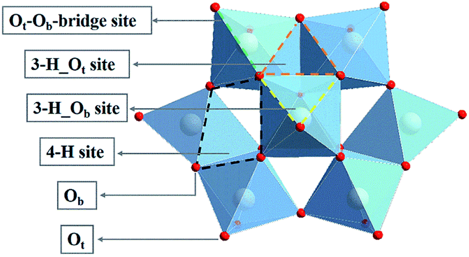 | ||
| Fig. 1 Structure of an α-Keggin type polyoxometalate. | ||
In this work, by using first principles calculations and a series of filters, we have comprehensively investigated the electrocatalytic CO2RR activity of α-[SiMo12O40]4−-supported single metal catalysts in which the transition metals (Sc to Zn and Y to Cd) are from d-block elements in the periodic table. The geometric structure, stability and CO2RR catalytic activity of the studied SACs were systematically explored. Based on the screening results, we observed that TM@Na4SiMo12 (TM = Sc, Cr, Mn, Ti and V) have high catalytic activity for the CO2RR, and the HER is inhibited, which are expected to be potential electrocatalysts for the CO2RR. Particularly, the limiting potential (UL) for the CO2RR catalyzed by Cr@Na4SiMo12 is only −0.23 V. Under the equilibrium potential of CO2/HCOOH, Mn@Na4SiMo12 is not disturbed by H2O. At the same time, POMs are found to play the role of electron sponge in the catalytic reaction. The present work is expected to provide valuable information for designing POM-based SACs and deepening the understanding the mechanism of the electrocatalytic CO2RR so as to realize the effective utilization of CO2.
2. Computational details
All geometric optimizations and single point energy calculations were performed using the Vienna Ab initio Simulation Package (VASP).37,38 The generalized gradient approximation (GGA) with the Perdew–Burke–Ernzerhof (PBE)39 exchange–correlation functional was chosen to describe the exchange–correlation interactions, and the DFT-D3 method was chosen to correctly describe van der Waals (vdW) interactions.40 A plane wave cutoff energy of 450 eV was used. The geometric structure was optimized by cubic cells with a side length of 30 Å, and the Brillouin zone was sampled using only the Γ point, until the convergence criteria of energy and force were less than 10−4 eV and 0.04 eV Å−1, respectively. The charge transfer was obtained based on the Bader charge analysis. To investigate the chemical bonding between the TM atom and the adsorbate, we performed crystal orbital Hamilton population (COHP) analysis,41–43 as implemented in the LOBSTER code.44The adsorption energy (Eads) was calculated using the following equation:
| Eads = EA–S − ES − EA | (1) |
The Gibbs free energy change (ΔG) was calculated using the computational hydrogen electrode (CHE) model developed by Nørskov et al.,45 and is defined as:
| ΔG = ΔE + ΔEZPE − TΔS + ΔGpH + ΔGU | (2) |
![[thin space (1/6-em)]](https://www.rsc.org/images/entities/char_2009.gif) 10 × pH, where kB is the Boltzmann constant, and the value of pH was set to be zero in this work. ΔGU = −neU, where n is the number of transferred electrons and U is the electrode potential relative to the standard hydrogen electrode (SHE). The UL of the reaction is obtained by using the formula UL = −ΔGmax/e. A conductor-like screening model (COSMO) was considered to simulate the water solvent environment throughout the whole process.47 The energy correction of the solvent effect was implemented under an implicit solvation model (named VASP sol) developed by Hennig and colleagues.48,49 In order to evaluate the stability of Na4SiMo12, an ab initio molecular dynamics (AIMD) simulation was performed by using the PBE functional and PAW pseudopotential. The Nose–Hoover method was used to control the temperature.50 AIMD simulation in the NVT ensemble was carried out at 500 K with a time step of 1.0 fs for a total of 10 ps.
10 × pH, where kB is the Boltzmann constant, and the value of pH was set to be zero in this work. ΔGU = −neU, where n is the number of transferred electrons and U is the electrode potential relative to the standard hydrogen electrode (SHE). The UL of the reaction is obtained by using the formula UL = −ΔGmax/e. A conductor-like screening model (COSMO) was considered to simulate the water solvent environment throughout the whole process.47 The energy correction of the solvent effect was implemented under an implicit solvation model (named VASP sol) developed by Hennig and colleagues.48,49 In order to evaluate the stability of Na4SiMo12, an ab initio molecular dynamics (AIMD) simulation was performed by using the PBE functional and PAW pseudopotential. The Nose–Hoover method was used to control the temperature.50 AIMD simulation in the NVT ensemble was carried out at 500 K with a time step of 1.0 fs for a total of 10 ps.
3. Results and discussion
3.1 Calculation model of TM@Na4SiMo12
A previous study has proved that the incorporation of counterions into the computational models is crucial to accurately reproduce the properties of polyoxoanions.51 In this work, the charge of α-[SiMo12O40]4– (SiMo12) was compensated by using four sodium ions to ensure the electroneutrality of the system. Based on the experimental result, we constructed a preliminary geometric model of the adsorption of Na4SiMo12 on graphene.34 After optimization, the average distance between the Na4SiMo12 and graphene is 2.95 Å (Fig. 2a and c). In order to understand the interaction between Na4SiMo12 and graphene, the charge density difference of Na4SiMo12 adsorbed on graphene was analyzed and is shown in Fig. S1 of the ESI.† Herein, yellow represents the electron density accumulation region, and cyan represents the electron density depletion region. We can see the obvious electron transfer from the counterions to SiMo12, indicating that the SiMo12 and counterions have strong interaction, while the charge distribution on graphene is negligible, indicating that the interaction between graphene and Na4SiMo12 is weak, and that graphene plays the role of conductive support in the experiment. Thus, graphene will not be taken into account in the following calculations in order to reduce computational cost (Fig. 2b and d).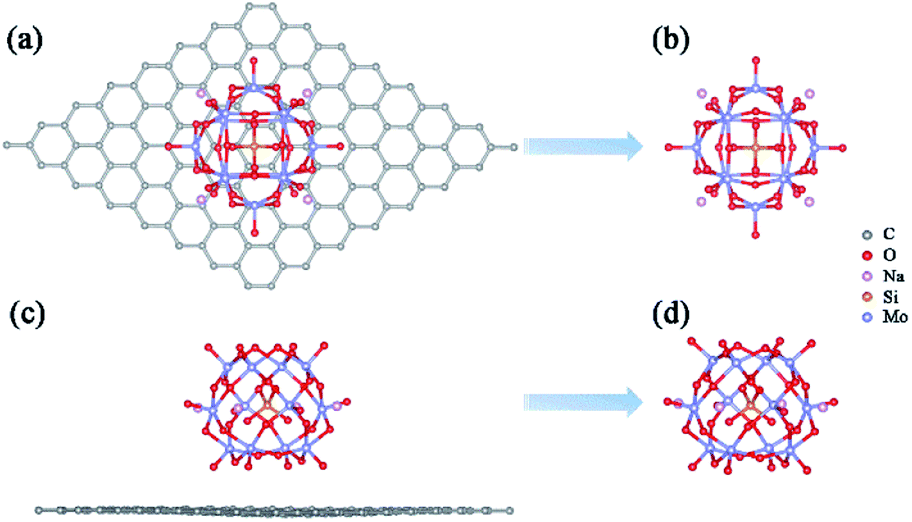 | ||
| Fig. 2 Top views (a and b) and side views (c and d) of the most stable structures of Na4SiMo12 loaded with or without graphene. | ||
Previous studies have shown that Pt atom dispersed on PMA and the most stable adsorption site is 4-H site.34,36 In addition to the 4-H site, the other sites of the Keggin type anion, such as 3-H_Ot, 3-H_Ob, and Ot–Ob-bridge, may also trap metal atoms. Taking Sc and Y as examples, all possible adsorption sites were studied to verify the most stable adsorption site on Na4SiMo12. The optimized structures and calculated adsorption energies of the TMs (TMs = Sc and Y) on Na4SiMo12 are shown in Fig. S2 of the ESI.† It is found that the TMs prefer to anchor to the 4-H site of Na4SiMo12, which is consistent with the previous studies.34,36,52–55 Based on the above analysis, the calculation model of TM@Na4SiMo12 was confirmed and is shown in Fig. 3a, in which the TMs are anchored on the POM 4-H site.
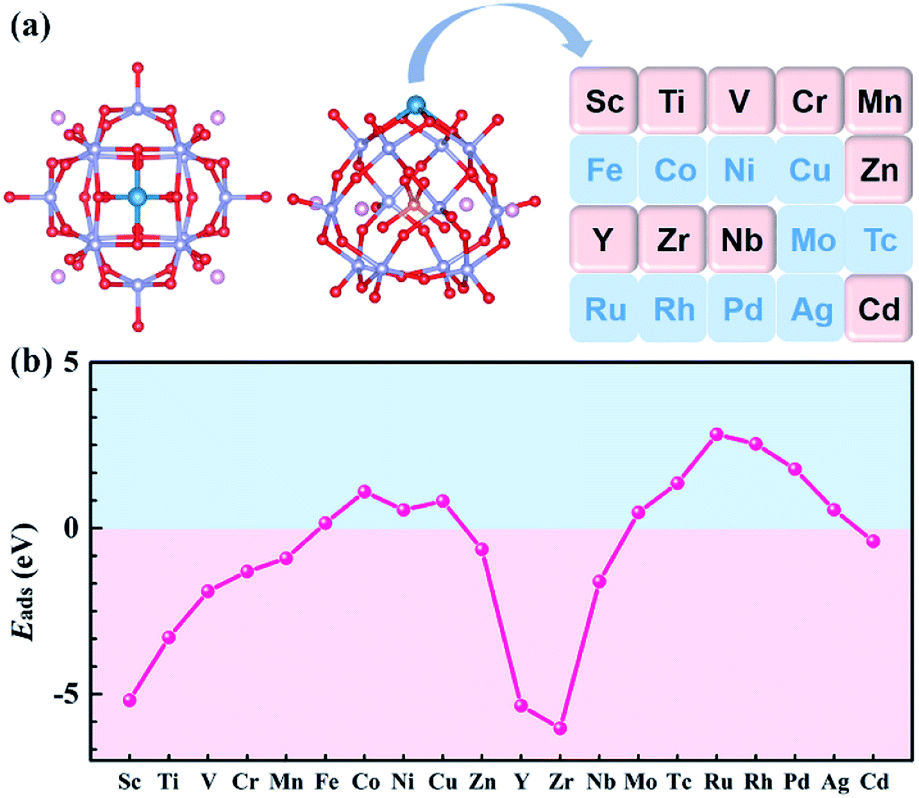 | ||
| Fig. 3 (a) Schematic illustration of the transition metals anchored on Na4SiMo12. (b) The adsorption energies of transition metal atoms anchored on Na4SiMo12. | ||
3.2 Stability of TM@Na4SiMo12
For SACs, due to the high surface energy and small migration barrier of metal atoms, agglomeration can easily occur during preparation and reaction, resulting in deactivation of the catalysts. In order to evaluate the stability of the studied POM-SACs, the Eads of single atoms anchored on the 4-H site of Na4SiMo12 was computed and the results are shown in Fig. 3b and Table S1 of the ESI.† The Eads was calculated using the equation:56| Eads = E(TM@Na4SiMo12) − E(Na4SiMo12) − μ(TM) | (3) |
The stability of Na4SiMo12 was further verified by AIMD simulation. No obvious structural deformation was observed after Na4SiMo12 was simulated at 500 K with a time step of 1.0 fs for a total of 10 ps, indicating its high thermal stability (Fig. S3 of the ESI†).
3.3 Electrochemical CO2RR on TM@Na4SiMo12
To further clarify the role of anchored transition metals in the catalytic cycle, the charge density difference of the system doped with transition metals was analyzed by taking Cr@Na4SiMo12 as an example (Fig. S5a of the ESI†). The charge density difference shows that the electron transfers from the anchored Cr atom to the neighboring oxygen atoms, and the Bader charge analysis (Fig. S8 of the ESI†) suggests that the Cr atom is positively charged due to losing 1.45e, and chemical bonds are formed between the Cr atom and the oxygen atoms of Na4SiMo12. The partial density of states (PDOS) of Cr@Na4SiMo12 was further analyzed and is shown in Fig. S5b of the ESI† in which the d orbitals of the Cr atom strongly hybridize with the p orbitals of adjacent O atoms near the Fermi level (EF). The d orbitals of Cr near the Fermi level show high reactivity, which may trigger adsorption in the catalytic cycle.
 | ||
| Scheme 1 All considered reaction pathways for CO2 reduction on TM@Na4SiMo12. | ||
 | ||
| Fig. 4 Free energy change (ΔG) of the first protonation step in the CO2RR and HER on TM@Na4SiMo12. | ||
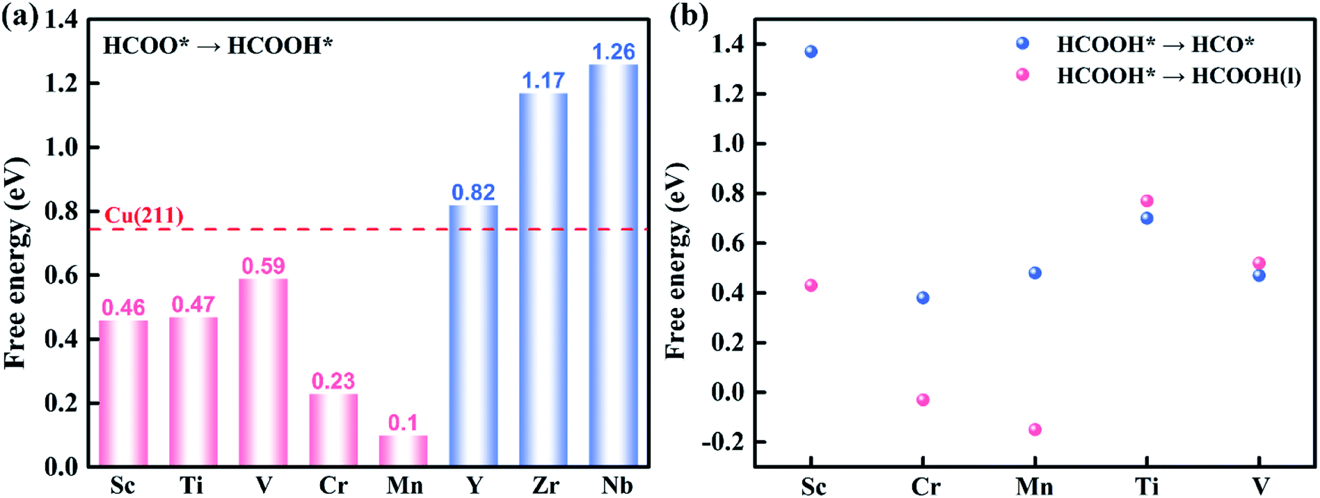 | ||
| Fig. 5 (a) The ΔG of HCOO* + e− + H+ → HCOOH* on TM@Na4SiMo12 (TM = Sc, Ti, V, Cr, Mn, Y, Zr and Nb). The screening criterion for catalytic activity is set to ΔG < 0.74 eV (red dashed line). (b) The ΔG for HCOOH* hydrogenation (HCOOH* + e− + H+ → HCO* + H2O (l)) and desorption (HCOOH* → HCOOH (l) + *) on TM@Na4SiMo12 (TM = Sc, Cr, Mn, Ti and V). | ||
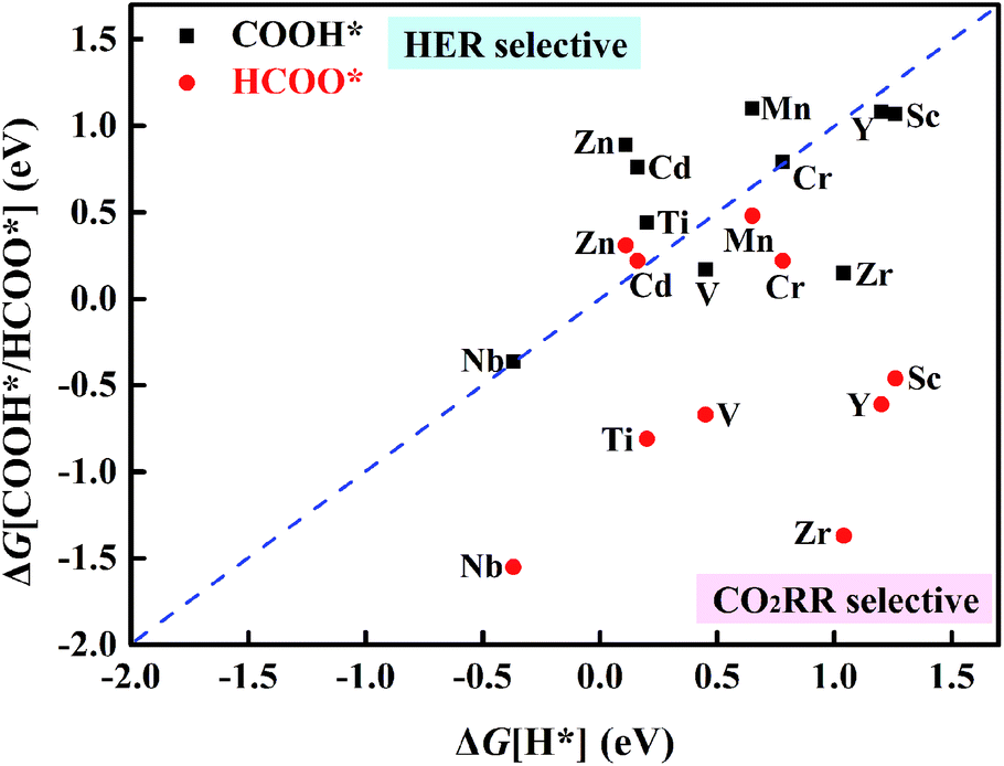
HCOOH* can be desorbed (HCOOH* → HCOOH (l) + *) from the catalyst or further hydrogenated (HCOOH* + H+ + e− → HCO* + H2O (l)). As shown in Fig. 5b, the HCOOH* desorption on TM@Na4SiMo12 (TM = Sc, Cr, and Mn) is easier than further hydrogenation, indicating that these three catalysts tend to produce HCOOH. In contrast, the HCO* intermediate is formed on Ti and V@Na4SiMo12 with ΔG of 0.70 eV and 0.47 eV, which are lower than the ΔG of HCOOH* desorption (0.77 eV and 0.52 eV). Therefore, the subsequent protonation process will be considered for Ti and V@Na4SiMo12.
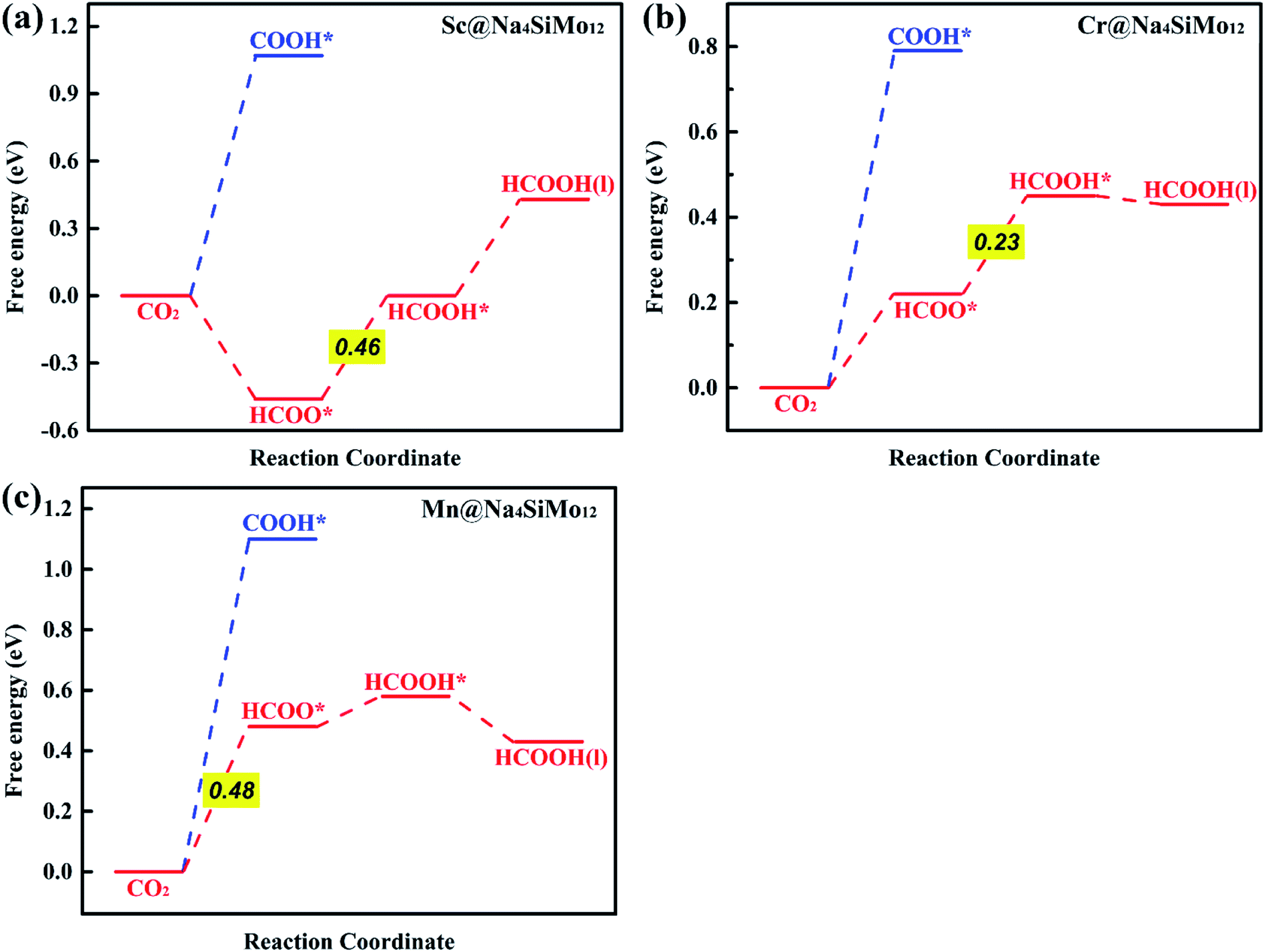 | ||
| Fig. 6 Calculated free energy diagrams for the electrochemical CO2RR on (a) Sc@Na4SiMo12, (b) Cr@Na4SiMo12 and (c) Mn@Na4SiMo12. | ||
First, the H+ + e− pair attacks the carbon atom of CO2 to form HCOO*. It should be noted that the ΔG for CO2 + H+ + e− → HCOO* on Sc@Na4SiMo12 is −0.46 eV, while for Cr and Mn@Na4SiMo12, the ΔG is 0.22 eV and 0.48 eV, respectively. Afterwards, HCOO* can be further reduced to form HCOOH* on TM@Na4SiMo12 (TM = Sc, Cr and Mn) with ΔG of 0.46, 0.23, and 0.10 eV, respectively, which are less than the ΔG of HCOOH* hydrogenation to HCO*. Therefore, for TM@Na4SiMo12 (TM = Sc, Cr and Mn), HCOOH* will not undergo further hydrogenation and is released in the form of a liquid. For Sc and Cr@Na4SiMo12, the PDS is the step of HCOO* → HCOOH* with UL of −0.46 V and −0.23 V, respectively. For Mn@Na4SiMo12, CO2 → HCOO* is the PDS with UL of −0.48 V.
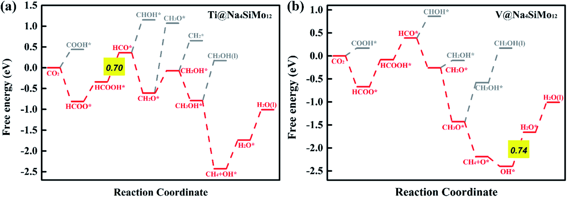 | ||
| Fig. 7 Calculated free energy diagrams for the electrochemical CO2RR on (a) Ti and (b) V@Na4SiMo12. | ||
For V@Na4SiMo12, once the intermediate CH2O* is obtained, subsequent H+ + e− pairs continue to attack the C atom until the C–O bond is broken and the CH4 molecule is released. Due to the weak adsorption energy of CH4 (−0.40 eV), it eventually desorbs from the surface as a product. The remaining O* undergoes two successive hydrogenation steps to produce an H2O molecule, and the corresponding free energy changes are −0.21 eV and 0.74 eV, respectively. For V@Na4SiMo12, the most favorable reaction pathway is CO2 → HCOO* → HCOOH* → HCO* → CH2O* → CH3O* → CH4 + O* → OH* → H2O, and the PDS is the step of OH* → H2O with UL of −0.74 V.
In summary, TM@Na4SiMo12 (TM = Sc, Cr, Mn, Ti and V) are promising high efficiency SACs for the electrochemical CO2RR with low UL, and are superior to the Cu (211) catalyst (−0.74 V).61 The competition between the H2O and CO2 adsorption also needs to be investigated.62 To further evaluate the stability of the above TM@Na4SiMo12 (TM = Sc, Cr, Mn, Ti and V) in water, we calculated the surface Pourbaix diagrams as a function of the standard hydrogen electrode (USHE) and pH. As shown in Fig. S9 of the ESI,† when pH = 0, TM@Na4SiMo12 (TM = Sc, Cr, Mn, Ti and V) require voltages of −0.80, −0.60, 0.43, −1.34, and −0.99 V, respectively, to protect the catalyst from being covered by OH* in water. When the actual potential is higher than the cathodic protection potential, the TM anchored on Na4SiMo12 begins to be covered by OH* in water. These catalysts are oxidized by O* when the USHE values increase to 0.88, −0.20, 0.66, −0.42, and −0.62 V, respectively. In this work, the equilibrium potential of CO2/HCOOH and CO2/CH4 is −0.22 and −0.13 V, respectively. Therefore, the catalyst should possess a high stability in water below the equilibrium potential of CO2/HCOOH or CO2/CH4. The results show that under the conditions of equilibrium potential, Mn@Na4SiMo12 will remain exposed and will not be disturbed by H2O. In contrast, TM@Na4SiMo12 (TM = Sc, Cr, Ti and V) will be covered by OH*, affecting the performance of the CO2RR.
It can be seen that Cr@Na4SiMo12 has a high catalytic activity for CO2 reduction to HCOOH, while the selectivity of the CO2RR is not good due to the competition from H2O. In comparison, Mn@Na4SiMo12 has high selectivity and relatively good catalytic performance (UL = −0.48 V).
3.4 Difference in the catalytic activity of TM@Na4SiMo12
To gain insight into the catalytic performance of TM@Na4SiMo12 (TM = Sc, Cr, Mn, Ti and V), the PDOS of CO2 adsorbed on TM@Na4SiMo12 was calculated and is shown in Fig. 8. It can be seen that Sc, Ti and V have obvious hybridization with CO2, and the hybridization range is wide, further indicating that TM@Na4SiMo12 (TM = Sc, Ti and V) have strong interaction with CO2. In order to evaluate the TM–O binding interaction from CO2 adsorbed on the TM@Na4SiMo12 (TM = Sc, Cr, Mn, Ti and V), integrated-crystal orbital Hamilton population (ICOHP) analysis was performed by integrating the band states up to the highest occupied energy level to measure the bond strength (Fig. 8). Moreover, the more negative the value of ICOHP, the stronger the bonding interaction. The results show that the ICOHP values change as follows: V (−3.19) < Ti (−3.07) < Sc (−2.58) < Cr (−2.50) < Mn (−2.00), and the bonding strength order is Mn–O < Cr–O < Sc–O < Ti–O < V–O. The relationship between the ΔG of CO2 hydrogenation to HCOO* and the ICOHP values of the TM–O bond is plotted in Fig. S7 of the ESI.† It is interesting to find an approximately linear correlation with R2 of 0.75. In other words, the TM–O bond with a smaller ICOHP value is stronger, resulting in a smaller ΔG value of CO2 → HCOO*, which also explains why the five catalysts have obvious differences in the first step of hydrogenation. In addition, we studied the relationship between the adsorption energies (Eads) of CO2 on the TM@Na4SiMo12 (TM = Sc, Cr, Mn, Ti and V) and the Bader charges of TMs (Fig. S8 of the ESI†). As the charge amount of transition metals increases, the Eads of CO2 increases, which in turn affects the catalytic performance of the CO2RR.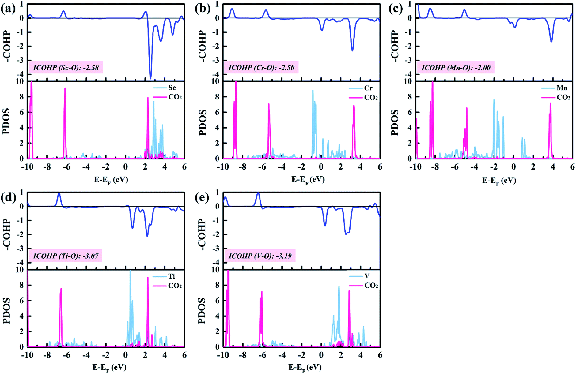 | ||
| Fig. 8 The PDOSs and COHPs of CO2 on TM@Na4SiMo12 (TM = Sc, Cr, Mn, Ti and V). | ||
To explore the role of TM@Na4SiMo12 in the electrochemical CO2RR, Ti@Na4SiMo12 is taken as an example to analyze the charge transfer between the reaction intermediates and the catalyst through Bader charge analysis along the optimal reaction pathway. As shown in Fig. 9, the studied system was divided into two parts including adsorbed CxHyOz species (moiety 1) and Ti@SiMo12 (moiety 2). Counterions were not included because their charges remain essentially unchanged during the reaction. Firstly, CO2 gains 0.07e by adsorption on Ti@SiMo12, and Ti@SiMo12 loses the same amount of charge. As the reaction goes on, Ti@SiMo12 continuously donates and accepts electrons during the electrochemical CO2RR, behaving as an “electron sponge”. Therefore, Ti@SiMo12 acts as an electron reservoir in the electrochemical CO2RR.
 | ||
| Fig. 9 Charge variation of the two moieties for Ti@Na4SiMo12 along the optical reaction pathway. Moieties 1 and 2 represent the adsorbed CxHyOz species and Ti@SiMo12, respectively. Negative and positive values indicate electron gain and loss. | ||
4. Conclusions
In summary, a series of SACs with TMs (TM = Sc, Ti, V, Cr, Mn, Fe, Co, Ni, Cu, Zn, Y, Zr, Nb, Mo, Tc, Ru, Rh, Pd, Ag, and Cd) anchored on Na4SiMo12 are proposed. Counterions are introduced into the calculation model, which is crucial to accurately reproduce the properties of polyoxoanions. Based on the DFT calculations, TM@Na4SiMo12 (TM = Sc, Ti, V, Cr, Mn, Zn, Y, Zr, Nb and Cd) are found to possess good stability, and might be synthesized in the experiment. Furthermore, Sc, Cr, Mn, Ti, and V@Na4SiMo12 are predicted to be efficient catalysts for the CO2RR due to the low UL; in particular, CO2RR by Cr@Na4SiMo12 has a very low UL of −0.23 V. Mn@Na4SiMo12 has high selectivity and good catalytic performance for CO2 reduction to HCOOH with UL of −0.48 V. In addition, POMs act as “electron sponges” during the electrochemical CO2RR, continuously accepting and donating electrons. This work provides valuable insights into the design of highly selective and efficient SAC electrocatalysts for the CO2RR.Conflicts of interest
There are no conflicts to declare.Acknowledgements
The authors gratefully acknowledge financial support by NSFC (21571031). We acknowledge the Institute of Theoretical Chemistry, Jilin University for providing the computational resources for this work.References
- S. Chu and A. Majumdar, Nature, 2012, 488, 294–303 CrossRef CAS PubMed.
- M. Aresta, A. Dibenedetto and A. Angelini, Chem. Rev., 2014, 114, 1709–1742 CrossRef CAS PubMed.
- J. C. Abanades, E. S. Rubin, M. Mazzotti and H. J. Herzog, Energy Environ. Sci., 2017, 10, 2491–2499 RSC.
- C. Costentin, M. Robert and J. –M. Savéant, Chem. Soc. Rev., 2013, 42, 2423–2436 RSC.
- Y. Li, S. H. Chan and Q. Sun, Nanoscale, 2015, 7, 8663–8683 RSC.
- J. Deng, H. Li, J. Xiao, Y. Tu, D. Deng, H. Yang, H. Tian, J. Li, P. Ren and X. Bao, Energy Environ. Sci., 2015, 8, 1594–1601 RSC.
- E. V. Kondratenko, G. Mul, J. Baltrusaitis, G. O. Larrazábal and J. Pérez–Ramírez, Energy Environ. Sci., 2013, 6, 3112–3135 RSC.
- J. Qiao, Y. Liu, F. Hong and J. Zhang, Chem. Soc. Rev., 2014, 43, 631–675 RSC.
- Y. Chen, K. Chen, J. Fu, A. Yamaguchi, H. Li, H. Pan, J. Hu, M. Miyauchi and M. Liu, Nano Mater. Sci., 2020, 2, 235–247 CrossRef.
- S. Piontek, K. junge Puring, D. Siegmund, M. Smialkowski, I. Sinev, D. Tetzlaff, B. Roldan Cuenya and U. –P. Apfel, Chem. Sci., 2019, 10, 1075–1081 RSC.
- S. Back, J. Lim, N.-Y. Kim, Y.-H. Kim and Y. Jung, Chem. Sci., 2017, 8, 1090–1096 RSC.
- S. Mou, T. Wu, J. Xie, Y. Zhang, L. Ji, H. Huang, T. Wang, Y. Luo, X. Xiong, B. Tang and X. Sun, Adv. Mater., 2019, 31, 1903499 CrossRef PubMed.
- M. Kunitski, N. Eicke, P. Huber, J. Köhler, S. Zeller, J. Voigtsberger, N. Schlott, K. Henrichs, H. Sann, F. Trinter, L. P. H. Schmidt, A. Kalinin, M. S. Schöffler, T. Jahnke, M. Lein and R. Dörner, Nat. Commun., 2019, 10, 1 CrossRef CAS PubMed.
- J. Kim, W. Choi, J. W. Park, C. Kim, M. Kim and H. Song, J. Am. Chem. Soc., 2019, 141, 6986–6994 CrossRef CAS PubMed.
- R. Kortlever, J. Shen, K. J. P. Schouten, F. Calle-Vallejo and M. T. M. Koper, J. Phys. Chem. Lett., 2015, 6, 4073–4082 CrossRef CAS PubMed.
- H. Wei, X. Liu, A. Wang, L. Zhang, B. Qiao, X. Yang, Y. Huang, S. Miao, J. Liu and T. Zhang, Nat. Commun., 2014, 5, 5634 CrossRef CAS PubMed.
- X. Fang, Q. Shang, Y. Wang, L. Jiao, T. Yao, Y. Li, Q. Zhang, Y. Luo and H.-L. Jiang, Adv. Mater., 2018, 30, 1705112–1705118 CrossRef PubMed.
- J. S. Jirkovsky, I. Panas, E. Ahlberg, M. Halasa, S. Romani and D. J. Schiffrin, J. Am. Chem. Soc., 2011, 133, 19432–19441 CrossRef CAS PubMed.
- W. Liu, L. Zhang, W. Yan, X. Liu, X. Yang, S. Miao, W. Wang, A. Wang and T. Zhang, Chem. Sci., 2016, 7, 5758–5764 RSC.
- Y.-G. Wang, D. Mei, V.-A. Glezakou, J. Li and R. Rousseau, Nat. Commun., 2015, 6, 6511–6519 CrossRef CAS PubMed.
- Y. Chen, S. Ji, C. Chen, Q. Peng, D. Wang and Y. Li, Joule, 2018, 2, 1242–1264 CrossRef CAS.
- H. Zhang, G. Liu, L. Shi and J. Ye, Adv. Energy Mater., 2018, 8, 1701343–1701367 CrossRef.
- C. Zhu, S. Fu, Q. Shi, D. Du and Y. Lin, Angew. Chem., Int. Ed., 2017, 56, 13944–13960 CrossRef CAS PubMed.
- Y. Cheng, S. Zhao, H. Li, S. He, J.-P. Veder, B. Johannessen, J. Xiao, S. Lu, J. Pan, M. F. Chisholm, S.-Z. Yang, C. Liu, J. G. Chen and S. P. Jiang, Appl. Catal., B, 2019, 243, 294–303 CrossRef CAS.
- K. Jiang, S. Siahrostami, T. Zheng, Y. Hu, S. Hwang, E. Stavitski, Y. Peng, J. Dynes, M. Gangisetty, D. Su, K. Attenkofer and H. Wang, Energy Environ. Sci., 2018, 11, 893–903 RSC.
- Y. Pan, R. Lin, Y. Chen, S. Liu, W. Zhu, X. Cao, W. Chen, K. Wu, W.-C. Cheong, Y. Wang, L. Zheng, J. Luo, Y. Lin, Y. Liu, C. Liu, J. Li, Q. Lu, X. Chen, D. Wang, Q. Peng, C. Chen and Y. Li, J. Am. Chem. Soc., 2018, 140, 4218–4221 CrossRef CAS PubMed.
- F. Yang, P. Song, X. Liu, B. Mei, W. Xing, Z. Jiang, L. Gu and W. Xu, Angew. Chem., Int. Ed., 2018, 57, 12303–12307 CrossRef CAS PubMed.
- M. Blasco-Ahicart, J. Soriano–López, J. J. Carbó, J. M. Poblet and J. R. Galan-Mascaros, Nat. Chem., 2018, 10, 24–30 CrossRef CAS PubMed.
- X. López, J. J. Carbó, C. Bo and J. M. Poblet, Chem. Soc. Rev., 2012, 41, 7537–7571 RSC.
- N. Mizuno and K. Kamata, Coord. Chem. Rev., 2011, 255, 2358–2370 CrossRef CAS.
- A. Proust, B. Matt, R. Villanneau, G. Guillemot, P. Gouzerh and G. Izzet, Chem. Soc. Rev., 2012, 41, 7605–7622 RSC.
- Y.-F. Song and R. Tsunashima, Chem. Soc. Rev., 2012, 41, 7384–7402 RSC.
- L. Vilà-Nadal, K. Peuntinger, C. Busche, J. Yan, D. Lüders, D.-L. Long, J. M. Poblet, D. M. Guldi and L. Cronin, Angew. Chem., Int. Ed., 2013, 52, 9695–9699 CrossRef PubMed.
- B. Zhang, H. Asakura, J. Zhang, J. Zhang, S. De and N. Yan, Angew. Chem., Int. Ed., 2016, 55, 8319–8323 CrossRef CAS PubMed.
- B. Zhang, H. Asakura and N. Yan, Ind. Eng. Chem. Res., 2017, 56, 3578–3587 CrossRef CAS.
- Y. Liu, X. Wu, Z. Li, J. Zhang, S.-X. Liu, S. Liu, L. Gu, L. R. Zheng, J. Li, D. Wang and Y. Li, Nat. Commun., 2021, 12, 4205 CrossRef CAS PubMed.
- G. Kresse and J. Hafner, Phys. Rev. B, 1997, 55, 7539–7548 CrossRef CAS.
- J. P. Perdew, J. A. Chevary, S. H. Vosko, K. A. Jackson, M. R. Pederson, D. J. Singh and C. Fiolhais, Phys. Rev. B, 1992, 46, 6671–6687 CrossRef CAS PubMed.
- J. P. Perdew, K. Burke and M. Ernzerhof, Phys. Rev. Lett., 1996, 77, 3865–3868 CrossRef CAS PubMed.
- S. Grimme, J. Comput. Chem., 2006, 27, 1787–1799 CrossRef CAS PubMed.
- R. Dronskowski and P. E. Bloechl, J. Phys. Chem., 1993, 97, 8617–8624 CrossRef CAS.
- V. L. Deringer, A. L. Tchougréeff and R. Dronskowski, J. Phys. Chem. A, 2011, 115, 5461–5466 CrossRef CAS PubMed.
- S. Maintz, V. L. Deringer, A. L. Tchougreeff and R. Dronskowski, J. Comput. Chem., 2013, 34, 2557–2567 CrossRef CAS PubMed.
- S. Maintz, V. L. Deringer, A. L. Tchougreeff and R. Dronskowski, J. Comput. Chem., 2016, 37, 1030–1035 CrossRef CAS PubMed.
- J. K. Nørskov, J. Rossmeisl, A. Logadottir, L. Lindqvist, J. R. Kitchin, T. Bligaard and H. Jónsson, J. Phys. Chem. B, 2004, 108, 17886–17892 CrossRef.
- Computational Chemistry Comparison and Benchmark Database; NIST Standard Reference Database Number 101, ed. R. Johnson III, National Institute of Standards and Technology, 2015, http://www.cccbdb.nist.gov Search PubMed.
- F. Neese and G. Olbrich, Chem. Phys. Lett., 2002, 362, 170–178 CrossRef CAS.
- M. Fishman, H. L. Zhuang, K. Mathew, W. Dirschka and R. G. Hennig, Phys. Rev. B, 2013, 87, 245402 CrossRef.
- R. A. Ojifinni, N. S. Froemming, J. Gong, M. Pan, T. S. Kim, J. M. White, G. Henkelman and C. B. Mullins, J. Am. Chem. Soc., 2008, 130, 6801–6812 CrossRef CAS PubMed.
- G. J. Martyna, M. L. Klein and M. Tuckerman, J. Chem. Phys., 1992, 97, 2635–2643 CrossRef.
- Z. Lang, X. Aparicio-Anglès, I. Weinstock, A. Clotet and J. M. Poblet, Inorg. Chem., 2017, 56, 3961–3969 CrossRef CAS PubMed.
- S. H. Talib, X. Yu, Q. Yu, S. Baskaran and J. Li, Sci. China Mater., 2020, 63, 1003–1014 CrossRef CAS.
- C.-G. Liu, Y.-J. Chu, L.-L. Zhang, C. Sun and J.-Y. Shi, Environ. Sci. Technol., 2019, 53, 12893–12903 CrossRef CAS PubMed.
- S. H. Talib, Z. Lu, X. Yu, K. Ahmad, B. Bashir, Z. Yang and J. Li, ACS Catal., 2021, 11, 8929–8941 CrossRef CAS.
- B. Zhang, G. Sun, S. Ding, H. Asakura, J. Zhang, P. Sautet and N. Yan, J. Am. Chem. Soc., 2019, 141, 8185–8197 CrossRef CAS PubMed.
- F. Li, H. Ai, C. Shi, K. H. Lo and H. Pan, Int. J. Hydrogen Energy, 2021, 46, 12886–12896 CrossRef CAS.
- J. N. Bronsted, Chem. Rev., 1928, 5, 231–338 CrossRef CAS.
- M. G. Evans and M. Polanyi, Trans. Faraday Soc., 1938, 34, 11–24 RSC.
- M. Moses-DeBusk, M. Yoon, L. F. Allard, D. R. Mullins, Z. Wu, X. Yang, G. Veith, G. M. Stocks and C. K. Narula, J. Am. Chem. Soc., 2013, 135, 12634–12645 CrossRef CAS PubMed.
- Z. Chen, J. Zhao, J. Zhao, Z. Chen and L. Yin, Nanoscale, 2019, 11, 20777–20784 RSC.
- A. A. Peterson, F. Abild-Pedersen, F. Studt, J. Rossmeisl and J. K. Nørskov, Energy Environ. Sci., 2010, 3, 1311–1315 RSC.
- J. Feng, J. Ni and H. Pan, J. Mater. Chem. A, 2021, 9, 10546–10561 RSC.
Footnote |
| † Electronic supplementary information (ESI) available. See DOI: 10.1039/d1ta08285j |
| This journal is © The Royal Society of Chemistry 2022 |