DOI:
10.1039/D1TA07903D
(Paper)
J. Mater. Chem. A, 2022,
10, 6165-6177
A polyoxometalate cluster-based single-atom catalyst for NH3 synthesis via an enzymatic mechanism†
Received
14th September 2021
, Accepted 29th November 2021
First published on 29th November 2021
Abstract
NH3 synthesis by the electrochemical N2 reduction reaction (eNRR) under mild conditions has attracted much attention. Here, by means of the first principles calculations, we propose a new strategy using a transition metal single-atom catalyst (SAC) anchored on a phosphomolybdic acid (PMA) cluster as a heterogeneous catalyst for the eNRR. We have systematically studied three reaction mechanisms, i.e., distal, alternating, and enzymatic pathways, respectively, for the eNRR on a Mo1/PMA SAC via a six-proton and six-electron process, and found that the preferred mechanism is the enzymatic pathway with the smallest overpotential (η) of 0.19 V. N2 is first strongly adsorbed on Mo1/PMA and then dissociated by the subsequent protonation process. In addition, we found that Mo1/PMA can impede the hydrogen evolution reaction (HER) process and thus promotes the eNRR selectivity. The high catalytic activity of Mo1/PMA for the eNRR is attributed to the high spin density on Mo, enhanced N2 adsorption, stabilization of the N2H* species, and the destabilization of the NH2* species. The present work is further extended to investigate the kinetics of the conversion of N2 to ammonia on Mo1/PMA via an enzymatic mechanism. Our results expose that the calculated activation energy barrier for the protonation of N2 to form the N2H4* species is kinetically and thermodynamically more favorable compared with other elementary steps. These results provide valuable guidance for NH3 synthesis using SACs at ambient temperature with high efficiency and low cost.
1. Introduction
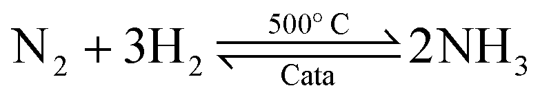
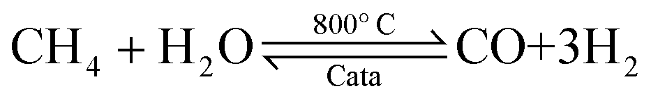
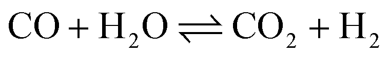
Ammonia (NH3) is essential to increase food resources for the increasing worldwide population,1,2 and it is also considered a chief hydrogen energy transporter3,4 due to its high hydrogen density, easy catalytic decomposition and the existence of well-developed technologies for production and distribution. Compared to other energy storage materials, NH3 has the benefit of no CO2 emission at the point of use.5,6 It is well known that NH3 is widely synthesized from atmospheric dinitrogen via the Haber–Bosch process (1), which is one of the most important developments in the nineteenth century.7,8 Currently, approximately 500 million tons of NH3 are synthesized per year. In this process, the reactants are H2 and N2 gases:9 H2 comes from the steam reforming of natural gas (2) at high temperatures or the water gas shift process (3). N2 comes from the atmosphere, and requires cryogenic separation from O2 and thus a large amount of energy.10,11| |  | (1) |
| |  | (2) |
| |  | (3) |
The electrochemical nitrogen reduction reaction (eNRR), which resembles N2 reduction with nitrogenases in bacteria, is fairly encouraging for nitrogen fixation on the grounds that the production of NH3 can occur at ambient pressure and temperature.12,13 Particularly, there is no hydrogen feed gas that requires separation from the NH3 product, and the eNRR process can be effectively tuned by the working potential, pH, electrolyte, etc., for optimizing the production yield of NH3.14,15 In recent years, Shi et al. reported that Au nanoparticles anchored on the CeOx–RGO hybrid support (Au/CeOx–RGO) exhibit excellent catalytic performances for the eNRR under the ambient environment.16 Liu et al.17 studied experimentally and theoretically the eNRR under ambient conditions using N-doped porous carbon (NPC) as the catalyst. They found that pyridinic and pyrrolic N are active sites, indicating that their contents are critical for stimulating ammonia production on NPC. Chen et al. studied iron supported on carbon nanotubes (CNTs) as the electrocatalyst for NH3 synthesis and found that the active sites may be related to specific carbon sites formed at the interface between the iron particles and CNTs.18
Transition metal (Mo-, Fe-, Ru-, and Co-) based materials are commonly used catalysts for the thermocatalytic activation of inert N2.19–28 Nishibayashi's group proposed that transition metal (Fe, Co, and Mo) dinitrogen complexes with an anionic PNP-pincer (PNP = 2,5-bis(ditertbutylphosphinomethyl)pyrrolidine) ligand can catalyze N2 fixation under mild reaction conditions.29 Jacobsen et al. for the first time prepared an effective and active cobalt-molybdenum nitride (Co3Mo3N) catalyst for the synthesis of ammonia.30,31 Manjunatha and Schechter reported that the RuPt/C catalyst shows better specificity and stability regarding the eNRR for the formation of NH3 at ambient pressure and temperature.32
For the development of efficient catalysts, both experimental and theoretical investigations play an important role. The notable current development33,34 of single-atom catalysts (SACs) and single-cluster catalysts (SCCs) has attracted significant interest in heterogeneous catalysis due to their high activity and selectivity. Therefore, significant efforts on SACs have been made for developing appropriate supports that can effectively anchor single metal atoms,35 without decreasing the performance of the appropriate support.36,37Recently, SACs have become a hot topic due to their unique performances, large precise surface area, numerous active centers, and maximum atom utilization.38–40The catalytic performance of various single transition metal atoms anchored on different supports has been extensively explored both experimentally and theoretically.41–44 Qiao and co-workers, for the first time, reported that the single Pt atom supported on iron oxide exhibits excellent catalytic activity and stability for both CO oxidation and superior oxidation of CO in H2.45Recently, Talib et al. reported that a single Cr atom embedded over a graphyne Cr1/GY surface is an efficient catalyst for the NO oxidation and reduction reaction under normal reaction conditions.46 Prior investigation proved that SACs exhibit massive potential in many catalytic reactions, such as CO oxidation, CO2 reduction reaction (CO2RR), oxygen evolution/reduction (OER/ORR), NO oxidation, and reduction reaction. For this reason, SACs arouse significant curiosity in N2 fixation and catalytic conversion of N2 into NH3.
Particularly, the notable advance in large-scale density functional theory calculations not only facilitates the exploration of efficient catalysts for N2 reduction but also brings further improvements in eNRR mechanisms.47–49 Zhao et al. reported that a single Mo atom anchored on a defective boron nitride monolayer is an efficient catalyst for N2 fixation, via an enzymatic pathway with a small overpotential value of 0.19 V.50 Luo et al. proposed an electrocatalyst of FeN3-embedded graphene for N2 fixation, and found that the highly spin-polarized FeN3 active center is accessible to catalyze N2 into NH3.51 By first-principles calculations and microkinetic investigation, Li and co-workers found that the Fe3 cluster on the θ-Al2O3(010) surface can be heterogeneous catalysts for ammonia synthesis.52 In addition, they reported biomimetic N2-to-NH3 thermal conversion on singly dispersed bimetallic catalyst Rh1Co3/CoO (011).53
However, there is no such report of SACs supported on clusters as catalysts for the eNRR. Herein, we carried out systematic theoretical studies of the electrocatalytic eNRR on Mo1/PMA under ambient conditions, via three possible pathways: alternating, distal and enzymatic mechanisms, respectively. The PMA cluster was reported to be an attractive support to stabilize transition metal atoms.54–60Our results reveal that the enzymatic mechanism has the lowest overpotential (η) of 0.19 V, and thus demonstrate that Mo1/PMA is a promising SAC for the eNRR.
2. Computational details
Geometry optimizations and energy calculations were performed by employing spin-polarized density functional theory (DFT) methods as implemented in the Vienna ab initio simulation package (VASP).61,62 To improve the calculation efficiency, projector augmented wave (PAW) pseudo-potentials were employed to define the interactions between the valence and core electrons.63–65In this work, the generalized gradient approximation (GGA) using the Perdew, Burke and Ernzerhof (PBE) exchange-correlation functional was employed.66,67 The valence electrons were described by ndx nsx for 3d, 4d, and 5d transition metal atoms (see ESI†), 4d55s1 for Mo, 2s22p4 for O, 3s23p3 for P, 2s22p3 for N, and 1s1 for H. The Kohn–Sham orbitals were expanded using plane-wave basis sets with an energy cutoff of 400 eV. The geometry optimizations were done with a convergence criterion of 10−5eV for the total energy and the maximum force less than 0.02 eVÅ−1. The Brillouin zone integration was performed with a 1 × 1 × 1 k-point grid to gain the required accuracy.68 The Bader charge analysis was performed to characterize the electron charge transfer.69–71 The PMA cluster was generated in a cubic unit cell (with 12 Mo atoms, one P atom and 40 O atoms), verified to be sufficient for inspecting the reaction mechanisms.57–60 A vacuum space of 20 Å was used to avoid the interaction among the complex bodies and their images.
In the eNRR process, six proton-coupled electron transfer (PCET) steps are involved, as shown by the following equation:
Each PCET step involves the transfer of one proton combined with an electron from a solution to an adsorbed species on the surface of catalysts. This is modeled by the computational hydrogen electrode (CHE) method proposed by Norskov et al.72–74 The Gibbs free energy change (ΔG) of every elementary step is calculated as follows:
| | | ΔG = ΔE + ΔZPE − TΔS + ΔGU + ΔGpH | (5) |
where Δ
E corresponds to the electronic energy difference directly obtained from DFT calculations, ΔZPE is the adjustment from the zero-point energies,
T is the temperature (
T = 298.15 k), Δ
S is the entropy change, Δ
GU corresponds to the free energy contribution associated with the electrode potential (
U), and Δ
GpH is the free energy contribution of H
+ ions, respectively. The Δ
GpH value can be determined as follows:
72–74| | | ΔGpH = ln(10) ×kBT× pH (or 0.059 eV x pH) | (6) |
where
kB is the Boltzmann constant, and the pH value was assumed to be zero because the overpotential is pH-independent here. The entropies and zero-point energies of the eNRR species were computed from the vibrational frequencies, in which just the adsorbate vibrational modes were explicitly considered while the catalyst cluster was fixed. The values for vibrational frequencies and entropies of molecules in the gas phase were taken from the NIST database.
75 In this work, the dimer method
76,77 has been applied to search for the transition states (TSs)
via the minimum energy path. All the TSs were further confirmed by vibrational frequency analysis. In this study, only one imaginary frequency was found in each TS configuration.
3. Results and discussion
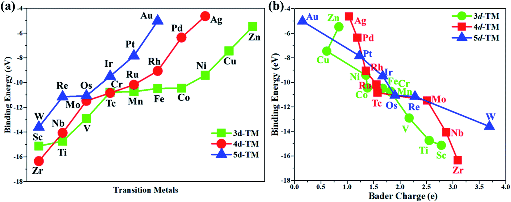
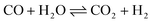
In this work, the PMA cluster was selected as the support to study single transition metal atom (TM= Sc, Ti, V, Cr, Mn, Fe, Co, Ni, Cu, Zn, Zr, Nb, Mo, Tc, Ru, Rh, Pd, Ag, W, Re, Os, Ir, Pt, and Au) catalysts for the eNRR, since PMA has appeared to be an attractive support to anchor transition metal atoms.78 It is notable that the Keggin-type PMA cluster is built by 12 MoO6 octahedra that connect their corners or edges to a central PO4 tetrahedron, and its fully optimized structure is shown in Fig. S1.† There are various possible coordination positions on the external oxygen atoms of the PMA cluster (see Fig. S1†), including two 3-fold hollow sites (3H–Oc and 3H–Obri), one 4-fold hollow site (4H) and one bridge site (b–Oc–Obri), respectively. It is found that transition metal atoms prefer to locate at the 4H site on the PMA cluster surface in a distorted square-planar geometry, which accords exactly with former work.54–56 Table S1† presents the key geometry parameters of transition metal atoms anchored on PMA. In PMA, the bond lengths of P–O, Mo–Oc, and Mo–Obri are 1.55 Å, 1.70 Å, and 1.93 Å, respectively. These results are in good agreement with previously reported experimental and theoretical studies.54–56 To find out an ideal catalyst for the eNRR, a series of transition metals (TM= Sc, Ti, V, Cr, Mn, Fe, Co, Ni, Cu, Zn, Zr, Nb, Mo, Tc, Ru, Rh, Pd, Ag, W, Re, Os, Ir, Pt, and Au) atoms from the periodic table were tested. As shown in Fig. S2,† all the TM atoms considered in this work are expected to anchor at the 4H site on the PMA cluster surface, which is consistent with previous theoretical calculations.54–56The calculated binding energies for TM atoms embedded on the PMA surface vary from −4 to −17 eV (Fig. 1a and Table S2†), indicating that these single metal atoms are strongly bound to the PMA support and our designed SACs exhibit high stability. The large binding energy indicates that TM adatoms can be robustly bound on the PMA cluster and are highly stable. To gain deeper insight into the strong binding interaction of the computed M1/PMA catalysts, we have performed the Bader charge analysis after doping TM adatoms. According to the Bader charge analysis, the result (Fig. 1b and Table S2†) shows that the electron transfer from the TM adatoms to the PMA support usually decreases with the increase of atomicity in the same period. For transition metals binding on PMA, a correlation has been found between binding energies and transferred charge, that is, the more transferred charge from transition metal atoms, the stronger the transition metal atom binding energy. Among all researched TM atoms, only Zn does not follow the rule.
 |
| | Fig. 1 (a) The calculated binding energies of transition metal (TM= Sc, Ti, V, Cr, Mn, Fe, Co, Ni, Cu, Zn, Zr, Nb, Mo, Tc, Ru, Rh, Pd, Ag, W, Re, Os, Ir, Pt, and Au) adatoms anchoring on the PMA cluster, and (b) the relationship between the calculated binding energies and Bader charge of TM adatoms anchored on the PMA cluster. All energies are specified in eV. | |
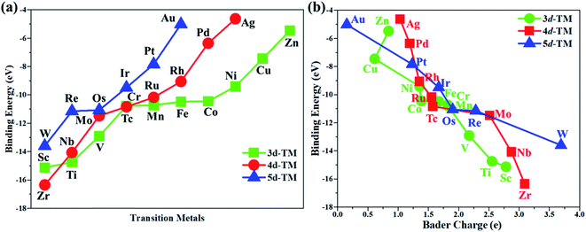
From previous computational studies,50 the high catalytic activity of transition metal atoms on the PMA cluster for the eNRR can be anticipated by the following criteria: enhanced N2 adsorption, stabilization of the N2H* species, and destabilization of the NH2* species.
According to the above criteria, to search for an optimal catalytic system for the eNRR, a series of transition metals (TM= Sc, Ti, V, Cr, Mn, Fe, Co, Ni, Cu, Zn, Zr, Nb, Mo, Tc, Ru, Rh, Pd, Ag, W, Re, Os, Ir, Pt, and Au) supported on M1/PMA are tested. At first, we calculated the ΔG value of N2 adsorption on the M1/PMA cluster (Fig. 2), in which only a small coverage of N2 molecules is considered. Presented in Fig. S3 and S4† are the computed geometries of the resultant N2 adsorption for both end-on and side-on configurations. After geometrical optimization, most of the side-on configurations (Sc, Ti, Mn, Fe, Co, Ni, Cu, Zn, Zr, Pd, and Ag) are changed to the end-on configurations. Our results showed that mostly these M1 are decent N2 adsorbers as indicated by the negative ΔG value, except Cr, Rh, and Ir which have positive ΔG values. Meanwhile, the positive ΔG value of the N2 adsorber means weak chemical adsorption, and the nominated atoms, Cr, Rh, and Ir, were not considered as SACs for the eNRR. Secondly, we further calculated the ΔG value for N2H* adsorbed over the M1/PMA cluster with the end-on configuration. As shown in Fig. 2, TM (Sc, Ti, Cr, Mn, Fe, Ni, Cu, Zn, Zr, Pd, Ag, Ir, Pt, and Au) candidates are ruled out as eNRR catalysts because large energy (ΔG> 1.0 eV) is required for the formation of the N2H* species. Compared with the other candidates, these catalysts are not suitable for the eNRR owing to the second criteria. Finally, nine M1 (V, Co, Nb, Mo, Tc, Ru, W, Re, and Os) systems were studied to make comparisons of the final elimination of the NH3 species. Our results showed that Co1/PMA and W1/PMA clusters are not eligible for the eNRR because large energy (ΔG> 1.0 eV) is required to destabilize the NH2* species (see Fig. 2). Thus, V, Nb, Mo, Tc, Ru, Re, and Os anchored on the PMA cluster serve as electrocatalysts eligible for the eNRR. These M1/PMA SACs show considerable adsorption strengths with N2, N2H* and NH2*species, which is necessary for the initiation of the eNRR. Consequently, to check their catalytic performance for the eNRR, we have studied in detail the reaction mechanism of the eNRR on these M1/PMA SACs under ambient reaction conditions.
 |
| | Fig. 2 Calculated Gibbs free energies of N2, N2H*, and NH2* species on various M1 (Sc, Ti, V, Cr, Mn, Fe, Co, Ni, Cu, Zn, Zr, Nb, Mo, Tc, Ru, Rh, Pd, Ag, W, Re, Os, Ir, Pt, and Au) atoms supported on the PMA cluster. | |
3.1 Hydrogen evolution reaction (HER)
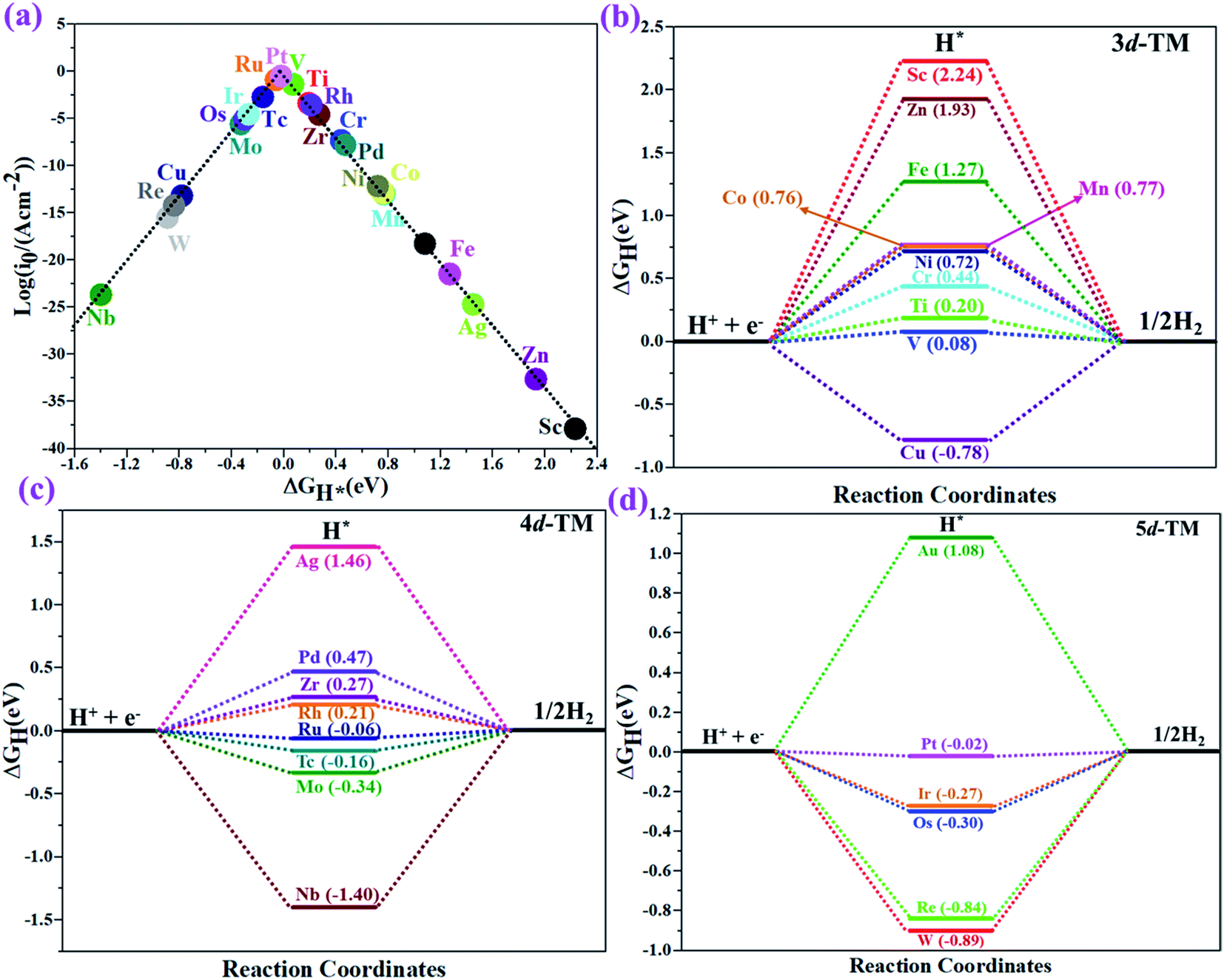
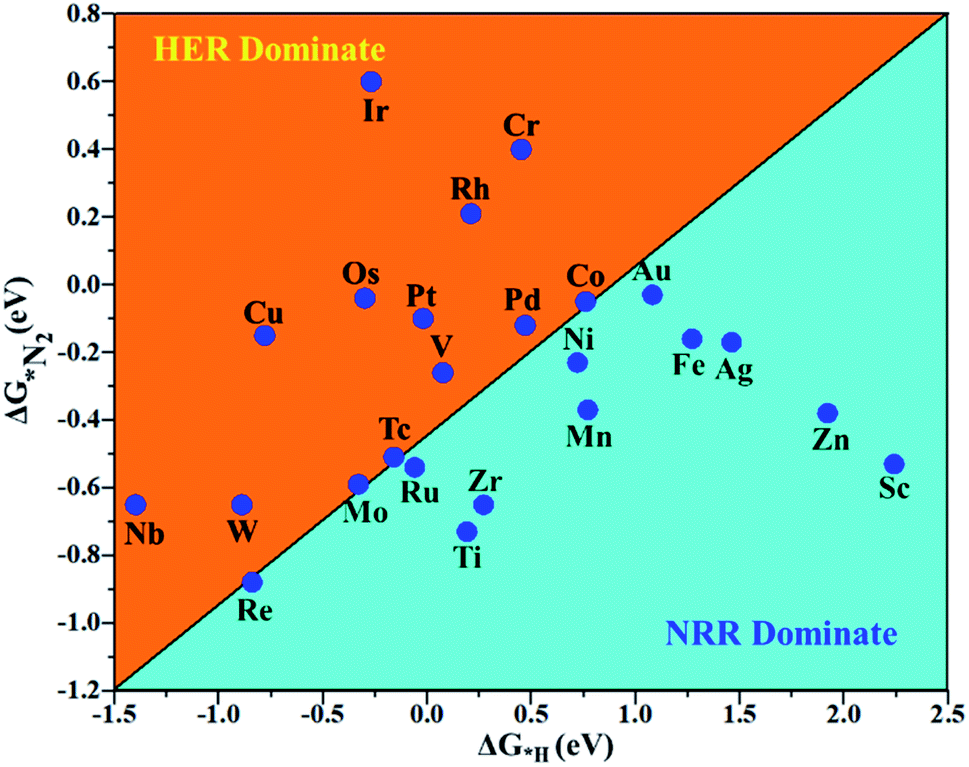
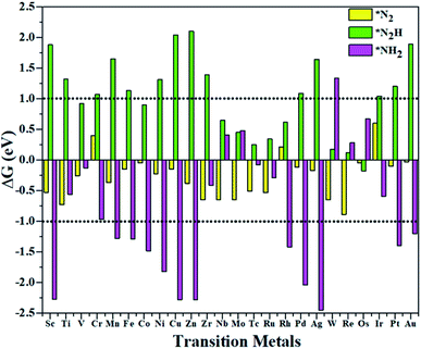
The hydrogen evolution reaction (HER) is a chief side reaction for the eNRR and can compete with the eNRR for the consumption of electrons and protons, subsequently reducing the energy efficiency and Faraday efficiency.79 Previously, the activity of M1/PMA (M1= Sc, Ti, V, Cr, Mn, Fe, Co, Ni, Cu, Zn, Zr, Nb, Mo, Tc, Ru, Rh, Pd, Ag, W, Re, Os, Ir, Pt, and Au) was assessed; it would be good to analyze the overpotential of the HER on the M1/PMA cluster. The HER occurs through the Tafel step [2Hads→ H2] or Heyrovsky step [Hads + (H+ + e−) → H2], with Hads denoting prevailing hydrogen bonded with M1. To accomplish the best HER activity, the ΔGH value should be close to an ideal value (ΔGH* = 0). A more positive or more negative value means strong or weak adsorption of hydrogen on the catalysts. In both cases, the inverse effect impedes the chemical reaction. In addition, it is helpful to examine whether M1/PMA is an important electrocatalyst for N2 adsorption. The HER activity of the PMA cluster was first explored for comparison. The value of ΔGH* for the O site of the PMA cluster is −2.32 eV, which implies that the H* atom binds with O (4H-site) too strongly. Therefore, the O site of the PMA cluster is not suitable for the HER. The ΔG values were calculated for adsorbed H* on the M1/PMA system to evaluate its HER activity. Fig. 3a shows a volcano curve for the relationship between ΔGH* and the exchange current (i0) density. Typically, the principles for deciding whether a catalyst is suitable for HER performance follow the standard rule of |ΔGH*| ≤ = 0.20 eV.80,81 In this work, it is found that Pt, V, Ru, Tc, and Ti catalysts reside on the top of the volcano curve with the highest catalytic activity and near to zero hydrogen adsorption energy. The other catalysts such as Nb, W, Re, Cu, Ir, Os, and Mo with negative ΔGH* values are situated around the left side of the volcano curve. The interactions of H* with these catalysts are too strong owing to very large negative ΔGH* values, which are situated at the bottom of the left side of the volcano curve with a very low i0 value. The M1/PMA (M1= Sc, Zn, Ag, Fe, Au, Mn, Co, Ni, Pd, Cr, Zr, and Rh) catalysts have positive ΔGH* values, signifying that it is difficult for the proton to adsorb on these systems, and are located at the bottom of the right side with also a very low i0 rate. Pt, Ru, V, Tc, and Ti atoms with ΔGH* values near zero achieve the maximum i0 rate, as they are located at the top of the volcano curve. As shown in Fig. 3b–d, for Sc, Zn, Ag, Fe, Mn, Au, Ni, Co, Zr, Cr, Pd, and Rh, the ΔGH* values are positive and above 0.2 eV at the 4H site, far away from the optimal value, signifying that these systems are not appropriate for the HER, while the values of ΔGH* for Nb, Cu, Ir, Os, Re, Mo, and W are all negative, indicating that the interaction of H* with M1/PMA is very strong, with a negative ΔGH* value. Consequently, the release of hydrogen inhibits the HER activity on these catalysts. On the other hand, the ΔGH* value for Pt, Ru, V, Ti, and V is less than 0.2 eV, which implies that the interaction of H* with these systems is weak, indicating that these catalysts could be active for the HER. To assess the selectivity of the M1/PMA catalysts, we firstly compared the ΔG values of H* and *N2 species on the M1/PMA cluster. The trends for the ΔG values of dinitrogen and hydrogen species adsorbed over the M1/PMA cluster are presented in Fig. 4. The N2 molecule prefers to adsorb mainly with the end-on configuration rather than the side-on configuration on all the M1/PMA systems studied. Fig. 4 demonstrates that Ru, Mo, Tc, and Re catalysts lie between the HER and eNRR dominant regions. The calculated Gibbs free energies of *N2 on Mo1 (−0.59 eV), Tc1 (−0.51 eV), Ru1 (−0.54 eV) and Re1 (−0.89 eV), respectively. These energies are much higher than the ΔG values of H* on Mo1 (−0.34 eV), Tc1 (−0.16 eV), Ru1 (−0.06 eV), and Re1 (−0.84 eV), respectively. For M = Mo, Tc, and Ru, the difference for the ΔG of *N2 and *H ranges from 0.25 eV to 0.50 eV. For Re1/PMA, the ΔG values of *N2 and *H are almost close. As presented in Fig S5,† N2 favorably adsorbs on the catalytic surface of Mo1/PMA, Ru1/PMA, and Tc1/PMA systems compared to H*, signifying that the selectivity of the eNRR is higher than that of the HER. Even at the limiting potential of the NRR on Mo (−0.35 V), the adsorption energy of *H (−0.69 eV) is only a little stronger than that of *N2 on Mo (−0.59 eV), indicating that adsorption of *H and *N2 is competitive adsorption. In addition, there are many strategies of suppressing the HER to boost the NRR selectivity: (a) limiting the proton and electron supply;82 (b) intentional design of the catalyst by incorporated Li+.83 Notably, all these catalysts possess negative ΔG values of *N2, indicating that they play a key role in activating the N2 molecule. It is rational to suggest that these M1/PMA catalysts can sustain high eNRR selectivity under experimental working environments. For Os, V, and Nb systems, the HER is dominant after applying voltage, indicating that the adsorption and activation of N2 in these systems are weak. Therefore, these catalysts are excluded as efficient eNRR catalyst candidates. In the following sections, we only select the Mo1/PMA SAC to explore the great advantage and electrocatalytic activity of the eNRR due to the following reasons: (1) Tc1 is a radioactive element, and Ru1 and Os1 are noble metals; (2) Mo1 is a non-noble metal and also a constituent of the FeMo cofactor84,85 which plays a significant role in the biological enzymatic N2 fixation; (3) compared with the calculated overpotential results, (see Fig. S6–S10†) Mo1/PMA has a lower overpotential than V1/PMA and Re1/PMA via distal, alternating and enzymatic pathways. Based on the above conversation, we establish that the adsorption of N2 is favorable on the Mo1/PMA catalyst.
 |
| | Fig. 3 (a) The volcano curve of the exchange current related to the free energy (ΔGH*) for hydrogen binding on a 4H site over the M1/PMA cluster. (b–d) Calculated free energy (ΔGH*) diagram for the HER at the equilibrium potential (U = 0.0 V) for the M1/PMA cluster. | |
 |
| | Fig. 4 Calculated Gibbs free energies of N2 and H2 adsorbed on the M1/PMA cluster, which are divided into the eNRR region (ΔG*H>ΔG*N2) and HER region (ΔG*H<ΔG*N2). | |
3.2 Geometric and electronic structure of Mo1/PMA
The optimized structure of the most stable Mo1/PMA cluster is shown in Fig. 5a. It is found that the Mo1 atom prefers to locate on the 4-hollow (4H) site of PMA, with a binding energy of −11.47 eV and bond lengths of Mo1–O of 1.95 and 1.92 Å, respectively. The most stable adsorption of the Mo atom on the 4H site shows that the Mo atom lies close to the PMA cluster and forms a strong bond with the neighboring oxygen atoms. The large binding energy implies that a strong chemisorption character has been built between the Mo atom and the PMA cluster. According to the Bader charge analysis, the Mo1 atom anchored on the PMA cluster is positively charged, with an atomic charge of +2.49|e| (see Table S2†). Remarkably, there is significant charge transfer from the Mo1 atom to the PMA cluster, which is consistent with the fact that the Mo1/PMA cluster possesses higher binding energy and strong stabilization of the Mo1 single atom. Fig. 5b shows the charge density difference of the Mo1/PMA cluster. It is observed that there is a loss of electron density on the Mo1 atom, which shows that the electron density flows from the Mo1 atom towards the nearest oxygen atoms. The charge transfer from the Mo1 center atom to the PMA cluster accounts for the strong interaction between the Mo1 atom and PMA. Remarkably, the magnetic moment of the Mo1 atom is 1.54 μB and the oxygen atom is −0.02 μB, which suggests that the spin density is mainly located on the Mo1 atom, with minor spin density on the neighboring O atoms. Such a large spin density on the Mo1 site may act as a key factor in activating the N2 molecule. To gain a deeper understanding of why the Mo1 atom binds so strongly on the PMA cluster, the spin-polarized PDOS was calculated as shown in Fig. 5c. The 4d orbital of the Mo1 atom is found to be strongly mixed with the 2p orbital of the PMA oxygen atoms, explaining the strong covalent metal–support interaction (CMSI) between the Mo1 and oxygen atoms at the 4H site of PMA. The spin-up and spin-down PDOS of the Mo1-4d orbital is asymmetric around the Fermi level. The presence of this partially occupied Mo1-4d orbital near the Fermi level indicates high reactivity, suggesting that it may play an important role in adsorbing and activating the adsorbates during the catalytic reaction.
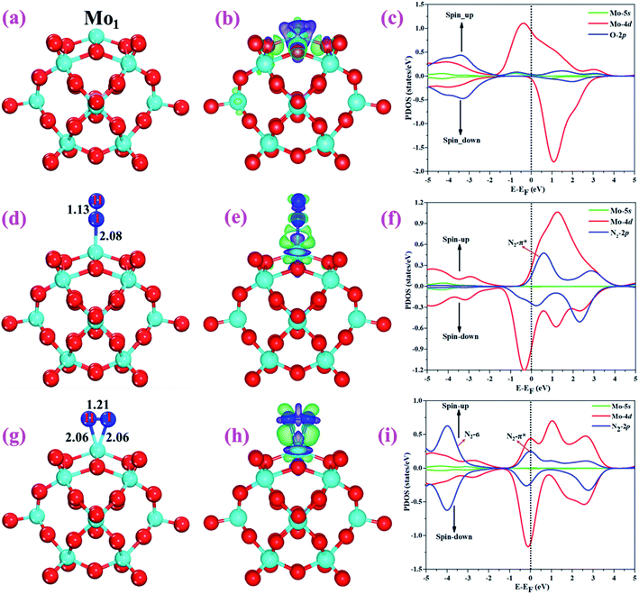 |
| | Fig. 5 Optimized structures of (a) Mo1/PMA, (d) N2 end-on, and (g) side-on adsorption on Mo1/PMA. Charge density differences of (b) Mo1/PMA, (e) N2 end-on, and (h) side-on adsorption on Mo1/PMA. The charge accumulation (depletion) regions are represented in green (purple) for the contour plots. The contour value of the charge difference density is ±0.05 a.u. (c), (f), and (i) the spin-polarized PDOS projected on the Mo1-4d and 5s (magenta and red) and O-2p (nearest oxygen atoms) and N-2p (ads) (blue) states. The Fermi level is set to zero. | |
3.3 Adsorption of N2 on Mo1/PMA
After studying the geometric structure, electronic structure, and stability of the Mo1/PMA cluster, we then move to examine its catalytic activity for the eNRR. N2 adsorption on Mo1/PMA is the first step to initialize the eNRR, and it plays a vital role in the consequent reaction pathway. Thus, we studied N2 adsorption on the Mo1/PMA cluster with end-on and side-on configurations, respectively.
For simplicity, the Mo1/PMA cluster was used as a support to study N2 adsorption behavior. Fig. 5d and g show the end-on and side-on configurations of N2 on Mo1/PMA with the ΔG values of −0.64 and −0.59 eV, respectively. Thus, the end-on N2 adsorption is more favorable energetically than the side-on N2 adsorption. Additionally, the newly formed Mo1–N bond length of the end-on configuration is 2.08 Å, and bond lengths of the side-on configuration are 2.06 and 2.06 Å, respectively. The bond length of adsorbed N2 is elongated from 1.11 Å (free N2 molecule) to 1.13 and 1.21 Å, respectively, indicating that the N2 molecule is activated. We also investigate the adsorption of H2O on Mo1/PMA to compare with the adsorption of N2. The calculated ΔG value of H2O is−0.31 eV, which implies that the adsorption of H2O is much weaker than the adsorption of N2. This indicates that the H2O molecule can't block the active site during the eNRR. According to the Bader charge analysis, 0.25 |e| end-on and 0.66|e| side-on transfer from Mo1/PMA to the N2 molecule, which indicates that the activation of the N2 bond agrees well with the transferred charge. To further confirm such behavior, we also calculated the charge density difference of N2 on Mo1/PMA, as shown in Fig. 5 (e and h), respectively. The lone pair electron transferred from N2 to the empty Mo1-4d orbital, and also there is back donation of electrons from the Mo1-4d orbital to the π*orbital of N2. Remarkably, the magnetic moments of Mo1 after N2 adsorption are 0.58 end-on and 0.61 μB side-on, respectively, and a little magnetic moment was found on the adsorbed N2 molecule:−0.15 end-on and 0.02 μB side-on, respectively. Hence, the large spin polarization on the Mo1/PMA cluster is responsible for the activation of N2. To gain more insight into the interaction between Mo1/PMA and the N2 molecule, the spin-polarized PDOS was examined, as shown in Fig. 5 (f and i), respectively. The transferred electrons mainly occupied the π* anti-bonding orbitals of N2. Then, the partial occupation of the anti-bonding orbitals of N2 causes the weakening of the N–N triple bond. Also, by comparing the Mo1-4d orbitals in Mo1/PMA, it can be been seen that the spin crossover and the magnetic moment significantly decrease near the Fermi level after N2 adsorption on Mo1/PMA. Therefore, the consequent process to convert the activated N2 to NH3 by protonation is highly probable.
3.4 eNRR on Mo1/PMA
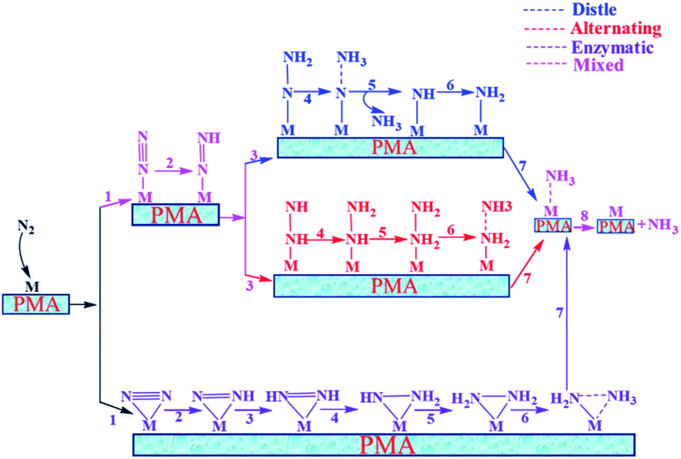
In general, we have considered that the eNRR mainly proceeds via three well-known possible pathways, namely distal, alternating, and enzymatic mechanisms, respectively. The six sequential protonation and reduction processes are involved in all three mechanisms, as shown in Fig. 6. In the following, we investigate all three mechanisms.
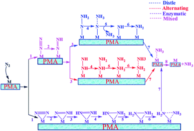 |
| | Fig. 6 Schematic description of the three typical pathways for N2 reduction to NH3 on the Mo1/PMA cluster. | |
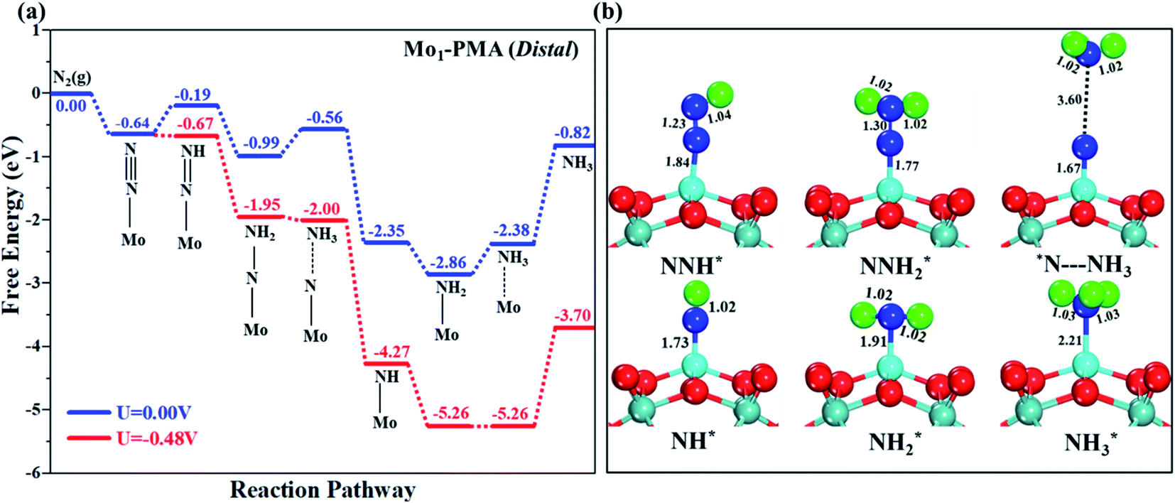
3.4.1 Distal pathway.
Fig. 7a and b illustrate the free energy profile and the corresponding optimized geometries of the elementary steps involved in the distal pathway, respectively. The pre-adsorbed end-on configuration of N2 on the Mo1/PMA cluster will be hydrogenated by adsorbing a proton coupled with transfer of an electron to form the N2H* species, with the proton attached to the distal nitrogen site. The bond length of N–H is 1.04 Å, and the bond length of N–N is 1.23 Å, which is further elongated compared to the pre-adsorbed N2 on the Mo1/PMA cluster (1.13 Å). The first step is slightly uphill in the free energy profile by 0.45 eV. In the second step, the proton coupled with an electron sequentially attacks the distal N2H* species. As a result, the N2H2*species is formed, and the Gibbs free energy profile is downhill by 0.80 eV. The bond length of N–H is 1.02 Å, and the bond length of the N–N is further elongated to 1.30 Å. In the third step, the first NH3 is released by the consecutive attacks of the proton-coupled with an electron in the pre-hydrogenated N site of the N2H2* species. While another N adatom remains on the Mo1 atom with the Mo1–N bond length of 1.67 Å, the Gibbs free energy profile is uphill 0.43 eV by the reduction of the N2H2*species to NH3 + N* species. In the fourth step, the N adatom remaining on the Mo1/PMA cluster reacts with another proton-coupled with an electron to form the NH* species, and the Gibbs free energy profile decreases by 1.79 eV. The bond length of N–H is 1.02 Å, and the bond length of Mo1–N is 1.73 Å, respectively. In the fifth step, the proton-coupled with an electron consecutively attacks the distal NH* species to form the NH2* species, and the energy profile further decreases by 0.51 eV. The bond length of N–H is 1.02 Å, and the bond length of Mo1–N is elongated up to 1.91 Å, respectively. In the last step, the sixth proton-coupled with an electron attacks the distal NH2* species to remove the second NH3 molecule from the Mo1/PMA cluster, and the Gibbs free energy value is 0.48 eV. Remarkably, the protonation of *NH2 to form the *NH3 species in this distal pathway is potentially a limiting step due to the large ΔG values (0.48 eV) among all elementary steps.
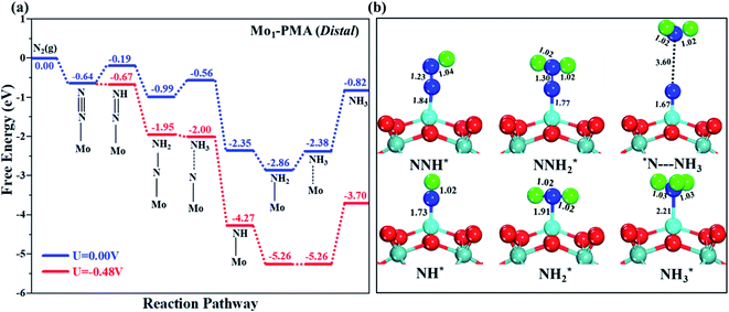 |
| | Fig. 7 (a) Free energy profile for the eNRR at zero and applied potentials (limiting potential) and (b) optimized geometric structures of various elementary steps of the eNRR pathway through a distal mechanism on the Mo1/PMA cluster. All bond lengths are given in Å. | |
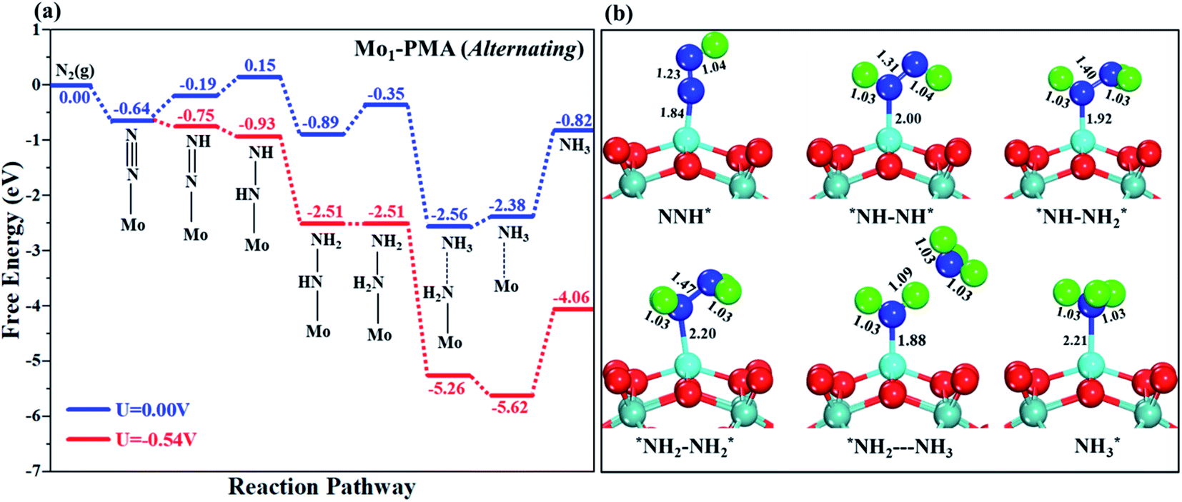
3.4.2 Alternating pathway.
Fig. 8a shows the Gibbs free energy profile for the alternating mechanism, and the optimized geometries of the corresponding elementary steps involved in the alternating pathway are shown in Fig. 8b. In the alternating mechanism, the pre-adsorbed end-on configuration of N2 on the Mo1/PMA cluster will be hydrogenated by adsorbing a proton coupled with transfer of an electron to form an N2H* species, with the proton attached to one nitrogen atom. The bond length of N–H is 1.04 Å, and the bond length of N–N is 1.23 Å, respectively. The first step is slightly uphill in the free energy profile by 0.45 eV. In the second step, the proton coupled with an electron sequentially attacks the second nitrogen atom, and as a result the N2H2*species is formed because the protonation alternatively occurs between the two nitrogen atoms in an alternating mechanism. The first NH3 molecule is released in the sixth step (schematic description). The bond lengths between the N–N atoms increase in every elementary step up to the release of the first NH3 molecule (N2H* 1.23 Å, N2H2* 1.31 Å, N2H3*1.40 Å, and N2H4*1.47 Å), respectively. Therefore, in the alternating pathway the protonation of N2 to form the N2H4*species is potentially a limiting step due to the large ΔG values of 0.54 eV between all elementary steps.
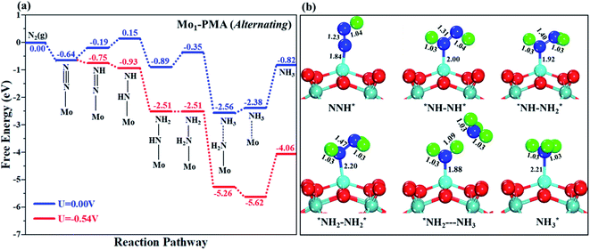 |
| | Fig. 8 (a) Free energy profile for the eNRR at zero and applied potentials (limiting potential) and (b) optimized geometric structures of various elementary steps of the eNRR pathway through an alternating mechanism on the Mo1/PMA cluster. All bond lengths are given in Å. | |
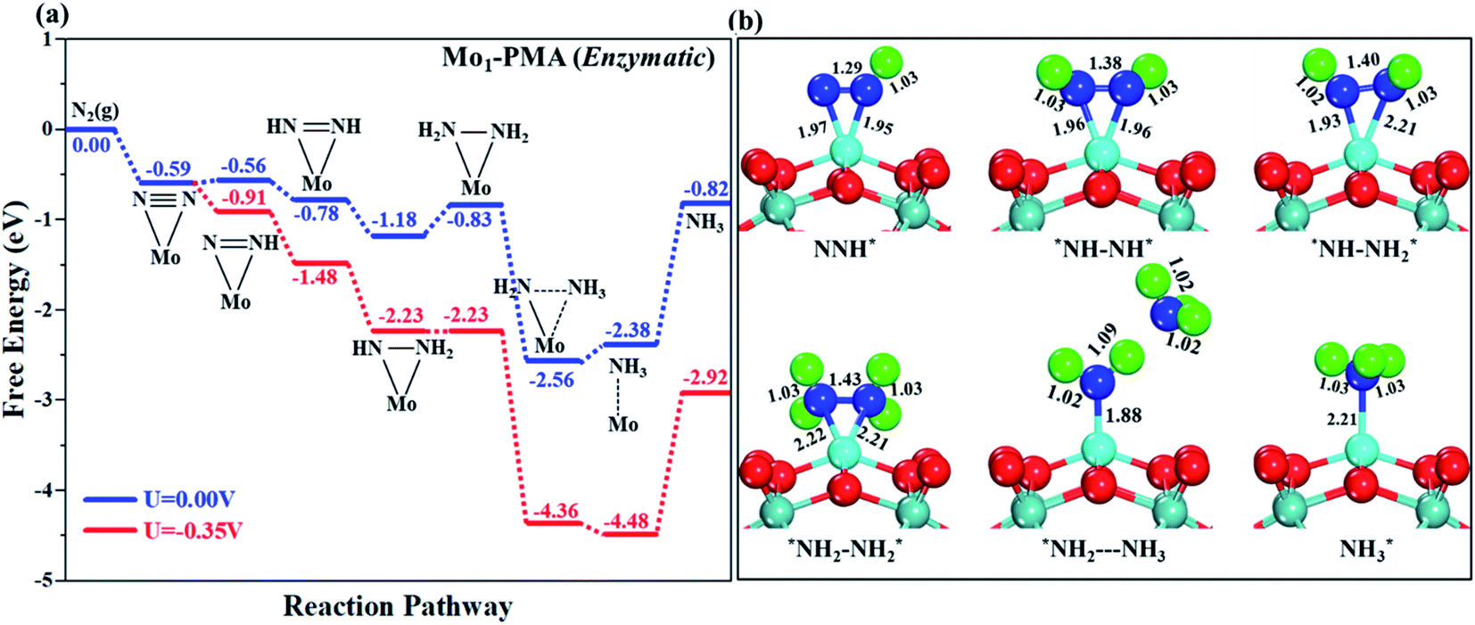
3.4.3 Enzymatic mechanism.
In our proposed enzymatic pathway, protonation between the two nitrogen atoms occurs consecutively, and the release of the first ammonia (NH3) molecule occurs at the sixth step (schematic description). Fig. 9(a and b) show the Gibbs free energy profile and the optimized structures of the corresponding fundamental steps involved in the enzymatic pathway, respectively. In the enzymatic mechanism, the side-on configuration of N2 on the Mo1/PMA cluster will be hydrogenated by adsorbing a proton coupled with transfer of an electron to form an N2H* species. The bond length of N–H is 1.02 Å, and the bond length of N–N is 1.29 Å, respectively. The bond lengths among N–N increase in every elementary step up to the release of the first NH3 molecule (1.29 Å N2H*, 1.38 ÅN2H2*, 1.40ÅN2H3*, and 1.43 Å N2H4*), respectively. In the enzymatic pathway, the key energy barrier for the protonation of the N2* species to NH3* is 0.35 eV (N2H3* to N2H4*), which is lower than that of distal (0.48 eV) and alternating (0.54 eV) pathways, respectively. Noticeably, the eNRR occurs over Mo1/PMA via the enzymatic pathway due to the lower overpotential.
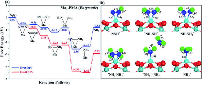 |
| | Fig. 9 (a) Free energy profile for the eNRR at zero and applied potentials (limiting potential) and (b) optimized geometric structures of various elementary steps of the eNRR pathway through an enzymatic mechanism on the Mo1/PMA cluster. All bond lengths are given in Å. | |
3.4.4 Mixed pathway.
A new pathway has recently been proposed for the eNRR86–90 in which the N2H2* species in the distal pathway would travel to an alternating pathway (denoted by arrows in the schematic description). Therefore, we also studied the mixed pathway on the Mo1/PMA cluster. According to our theoretical results, the Gibbs free energy for the protonation of adsorbed N2 to the N2H* species is unchanged (0.45 eV) in this mixed mechanism. In the mixed mechanism, the potential determining step is larger than that of the enzymatic mechanism, which is 0.35 eV. Thus, the enzymatic mechanism is more favorable than the mixed pathway.
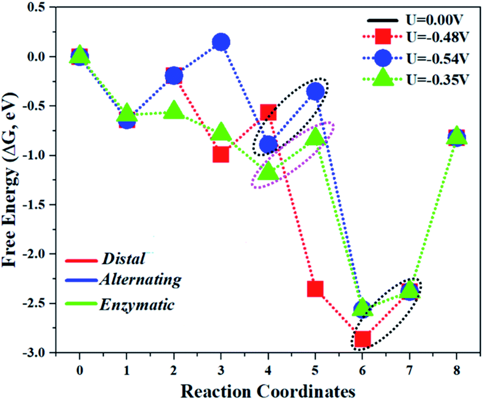
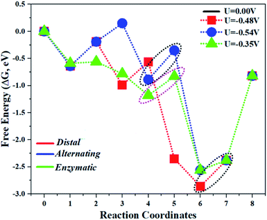
The comparison of the different reaction mechanisms in the electrocatalytic synthesis of ammonia on the Mo1/PMA cluster is summarized in Fig. 10. The calculated ΔG values of all the elementary steps are presented in Table S3.† The results indicate that the enzymatic pathway 0.35 eV has a lower energy barrier than the distal (0.48 eV) and alternating (0.54 eV) pathways, respectively. Thus, under ambient reaction conditions, the Mo1/PMA single-atom catalyst is potentially the more active catalyst for the eNRR.
 |
| | Fig. 10 The free energy surfaces for all three pathways of the eNRR on the Mo1/PMA cluster at zero potential via distal, alternating, and enzymatic mechanisms, respectively. | |
To describe the catalytic reactivity of the Mo1/PMA cluster, the overpotential (η) is calculated since it is a good indicator for the eNRR. A smaller value indicates a faster eNRR reaction. According to the computational hydrogen electrode (CHE) model, the value can be calculated using the following equation: η =Uequilibrium−Ulimiting, where Uequilibrium is the equilibrium potential of the eNRR. The equilibrium potential calculated in this work is −0.16 V for such a reaction. The Ulimiting is the applied potential that can be determined by eliminating the energy barrier of the rate-limiting step. Ulimiting = ΔG/e, where ΔG is the Gibbs free energy of the potential of the limiting step.
The limiting potentials of the eNRR on the Mo1/PMA cluster via the three mechanisms discussed above are −0.48, −0.54, and −0.35 V, respectively. Thus, the overpotential (η) values of these mechanisms are distal (−0.16) − (−0.48) = 0.32 V, alternating (−0.16) − (−0.54) = 0.38 V and enzymatic (−0.16) − (−0.35) = 0.19 V, respectively. Therefore, the eNRR occurring on an isolated Mo1/PMA cluster prefers to proceed via the enzymatic mechanism due to the minimum overpotential (η) 0.19 V value. These values are smaller than that of the well-known Re (111) surface (0.50 V),86 and equal to that of the Mo–boron nitride monolayer (0.19 V).50 Therefore, a single Mo1/PMA cluster is likely to be a very promising SAC for the eNRR.
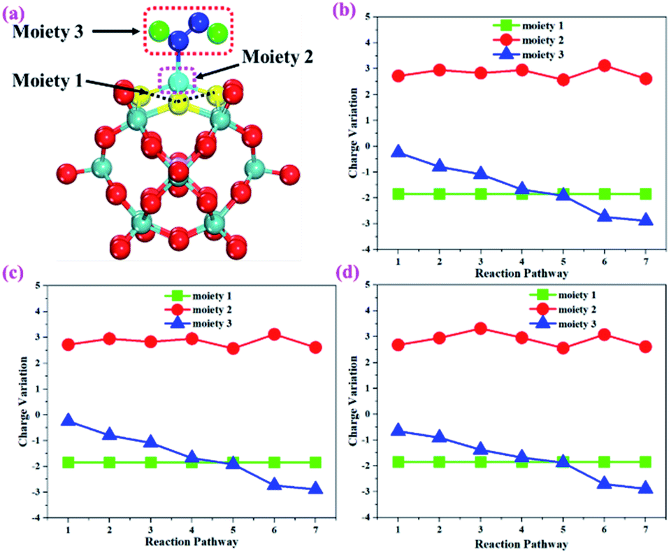
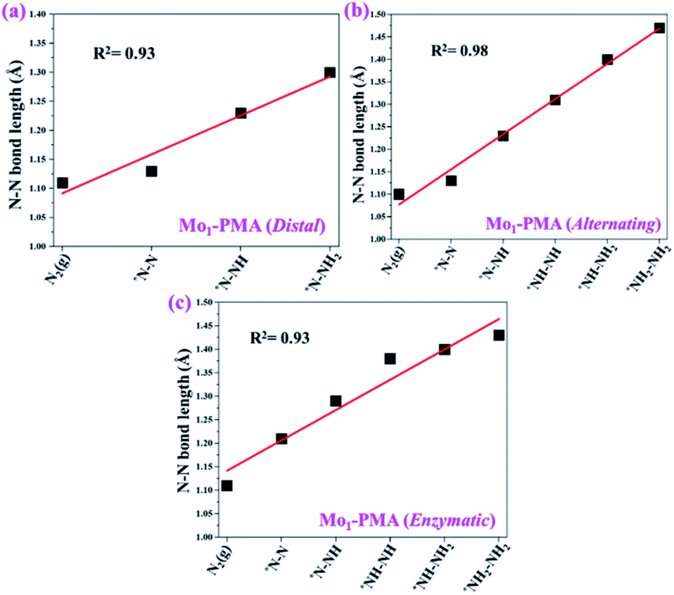
To gain more insights into the catalytic performance of the Mo1/PMA cluster for the eNRR, we have performed the Bader charge analysis in each elementary step (see Table S4†). Fig. 11a shows that each intermediate can be divided into their moieties: four oxygen atoms on the PMA cluster which are around the Mo1atom (moiety 1), the single metal atom (Mo1) (moiety 2) and the adsorbed NxHy species (moiety 3), respectively. It has been found that the N2 molecule gains 0.25|e| end-on and 0.66|e| side-on from the Mo1/PMA cluster by Bader charge analysis. For the consequent hydrogenation and reduction steps, Mo1/PMA serves as an electron reservoir of electron donation, which buffers the charge variation during N2 to NH3 conversion. Fig. 11 (b–d) show that a very small charge fluctuation occurs along the distal, alternating and enzymatic pathways, respectively. In all three pathways, moiety 1 has a similar charge. It can be seen that moiety 3 gains one electron from moiety 2 when a proton coupled with an electron interacts with the adsorbed N2 molecule. Thus, the Mo1/PMA cluster serves as an electron donor and the adsorbed NxHy species acts as the electron acceptor in the eNRR. In addition, we also found that the N–N bond lengths (see Fig. 12 and Table S5†) are elongated along distal, alternating, and enzymatic pathways till they are ruptured at the 4th step in the distal pathway [Fig. 7a andb] and the 6th step in the alternating and enzymatic pathways [Fig. 8a and b and 9a and b], suggesting the possibility of N2 activation on the Mo1/PMA cluster. Fig. 12 shows that the N–N bond length of adsorbed N2 on the Mo1/PMA cluster via distal, alternating, and enzymatic pathways increases linearly.
 |
| | Fig. 11 (a) Geometrical structure of the adsorbed NxHy species on the Mo1/PMA cluster, (b) charge variation of the three moieties along the distal, (c) alternating, and (d) enzymatic pathways, respectively. The moieties 1, 2 and 3 represent four oxygen atoms around the Mo1 atom, the single Mo1 atom, and the adsorbed NxHy species on the Mo1/PMA cluster. | |
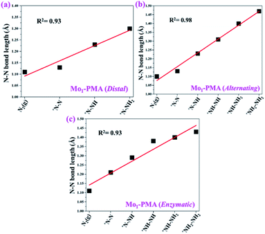 |
| | Fig. 12 N–N bond length along (a) distal, (b) alternating, and (c) enzymatic pathways over the Mo1/PMA cluster, respectively. The corresponding bond length values are presented in Table S5.† | |
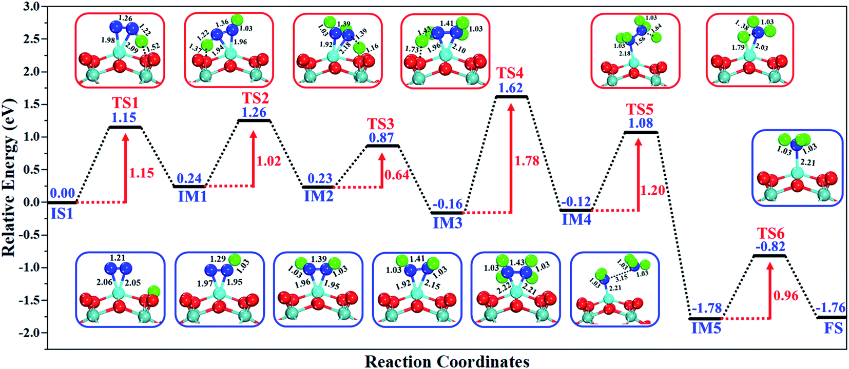
The excellent catalytic performance of the Mo1/PMA catalyst for the eNRR through the enzymatic mechanism is further confirmed by kinetic analysis. For a precise enzymatic mechanism, the potential energy diagram and the corresponding geometries of the reaction intermediates involved in the nitrogen reduction reaction are presented in Fig. 13 and Fig. S11.† The catalytic cycle shows that the N2 molecule is chemically adsorbed on the 4H site of the Mo1/PMA cluster through the side-on configuration, and the calculated adsorption energy is −0.58 eV. Fig. 13 illustrates that the activated N2 molecule is first protonated to produce the NNH* radical via the transition state (TS1), which has a barrier of 1.15 eV (imaginary frequency 572i cm−1). The N–N bond stretched from 1.21 to 1.29 Å with the N–H bond formation (1.03 Å) between the N2 molecule and H atom. Subsequently, the second proton interacts with the NNH* radical and forms an NHNH* species through the transition state (TS2). The calculated kinetic barrier (TS2) for NNH* → HNNH* conversion protonation is 1.02 eV (imaginary frequency 1310i cm−1). As a result, the N–N bond length is lengthened from 1.29 Å in the NNH* radical to 1.39 Å. During the third protonation step, the third proton interacts with the adsorbed HNNH* species and forms an *HNNH2 species via the transition state (TS3). Here TS3 has a kinetic barrier of 0.64 eV for the protonation of HNNH* → *HNNH2 species with one imaginary frequency (1016i cm−1). The bond length of N–N (*HNNH2) is 1.41 Å, which is further extended compared with that of the HNNH* species adsorbed on the Mo1/PMA cluster. The *HNNH2 species can be further hydrogenated to form the hydrazine species (H2NNH2*) through TS4 with kinetic barriers of 1.78 eV (imaginary frequency, 479i cm−1). The calculated N–N bond length is 1.43 Å, which suggests a single bond character among N atoms. Thus, the formation of the N2H4* species is the rate-limiting step among all six eNRR steps due to the high activation barrier, and these findings are in good agreement with the above thermodynamic and previous theoretical results.91 Next, the fifth hydrogenation occurs after the N–N bond cleavage, resulting in the formation of the first NH3 molecule, and the NH2* species remains on the Mo1/PMA cluster. The calculated kinetic barrier for the protonation of H2NNH2* → NH3 + NH2* species is 1.20 eV (TS5, imaginary frequency 1071i cm−1). Finally, the remaining NH2* species is further hydrogenated, leading to the formation of the second NH3 molecule by dissociating the Mo–N bond. The reaction energy and activation energy barrier for the protonation of NH2* → NH3 conversion are −3.76 eV (exothermic) and 0.96 eV (TS6, imaginary frequency 1431i cm−1). Overall, we find that the protonation of *HNNH2 → H2NNH2* species is the utmost challenging step among the six eNRR steps, both thermodynamically and kinetically. Subsequently, the second NH3 molecule is eliminated, and the dynamic site of Mo1/PMA could be recuperated to start another eNRR cycle.
 |
| | Fig. 13 Reaction profiles for the eNRR over the Mo1/PMA cluster via an enzymatic mechanism. All of the given energies are in electronvolt (eV). | |
Further, spin density analysis, spin magnetic moments, and Mo1 oxidation states can provide valuable information on all the elementary steps (distal, alternating, and enzymatic pathways) involved in the eNRR. From the calculated spin magnetic moments, the Mo1/PMA catalyst has a spin magnetic moment of 1.54 μB at the Mo12+ active center. The adsorbed N2, protonated H and desorbed species NH3 are the most important ones in the eNRR. However, the spin magnetic moment is quenched to 0.61 side-on and 0.58 μB end-on when N2 adsorbs on the Mo1/PMA cluster, indicating that Mo12+ is oxidized to Mo13+. The calculated spin density localization, spin magnetic moments and Mo1 oxidation states of all the elementary steps involved in the eNRR via distal, alternating, and enzymatic pathways are displayed in Table S6 and Fig. S12–S15,† which demonstrate that the spin density, magnetic moment and oxidation state change in all the elementary steps up to the release of the NH3 molecule. With the desorption of the NH3 molecule, the magnetic moment of the Mo1 atom in the final step increased to 1.37 μB and Mo13+ is again reduced to Mo12+. It is safe to assume that metals in the +II oxidation state are good candidates for the M1/PMA SAC in the eNRR.
4. Conclusions
In summary, by performing DFT calculations combined with the computational hydrogen electrode method, we have proposed a new SAC Mo1/PMA for activating N2 and converting it into NH3 under mild reaction conditions. Our results revealed that the single Mo1 atom could be stably embedded into the phosphomolybdic acid cluster that possessed outstanding catalytic activity towards the eNRR. The large spin polarization and charge transfer from the Mo1-4d orbital to the N2 2π* orbital are liable for the activation of N2. The eNRR process facilitated by the Mo1/PMA complex proceeds through an enzymatic mechanism with a low overpotential (η) of 0.19 V. In addition, we found that the Mo1/PMA cluster can impede the HER process and thus promote the eNRR selectivity. Therefore, our theoretical results suggest that Mo1/PMA is a promising SAC with excellent stability and high efficiency for N2 fixation.
Moreover, to explore the effective performance of the Mo1-PMA catalyst for converting N2 to NH3 through the enzymatic mechanism, the kinetic activation energy barriers were examined for comparison. From the potential energy profile of the enzymatic mechanism on Mo1/PMA, we found that the protonation of N2 to form the N2H4* species is a kinetic rate-determining step, with an activation barrier of 1.78 eV. The calculated kinetic results are in good agreement with thermodynamic results. Moreover, the spin magnetic moments and spin density analysis provide valuable information for all the elementary steps involved in the eNRR. This work provides valuable guidance for theory and experiment further to explore the potential of PMA-based SACs as eNRR electrocatalysts.
Conflicts of interest
The authors declare no competing financial interests.
Acknowledgements
We thank Prof. Ignacio Garzon Sosa and Assoc. Prof. Qi Yu for helpful discussion. This work was supported by the Natural Science Basic Research Program of Shaanxi Province (grant No. S2020-JC-WT-0001 and 2019JM-226), National Science Foundation of China (No. 22033005), and Guangdong Provincial Key Laboratory of Catalysis (No. 2020B121201002). The calculations were performed by using supercomputers at Tsinghua National Laboratory for Information Science and Technology and at SUSTech Supercomputing Center. X. Y. thanks the Special Funding for Transformation of Scientific and Technological Achievements in Qinghai Province (2018-GX-101).
References
- M. Nazemi, S. R. Panikkanvalappil and M. A. El-Sayed, NanoEnergy, 2018, 49, 316–323 CAS.
- H. J. van Grinsven, L. Bouwman, K. G. Cassman, H. M. van Es, M. L. McCrackin and A. H. Beusen, J. Environ. Qual., 2015, 44, 356–367 CrossRef CAS PubMed.
- M. Cruz and S. A. Ahmed, World Dev., 2018, 105, 95–106 CrossRef.
- M. D. Fryzuk, Nature, 2004, 427, 498–499 CrossRef CAS PubMed.
- A. Klerke, C. H. Christensen, J. K. Nørskov and T. Vegge, J. Mater.Chem., 2008, 18, 2304–2310 RSC.
- D. G. Capone and J. P. Montoya, Methods Microbiol., 2001, 30, 501–515 CAS.
- Y. Bicer, I. Dincer, G. Vezina and F. Raso, J. Environ. Manage., 2017, 59, 842–855 CrossRef PubMed.
- J. Otomo, M. Koshi, T. Mitsumori, H. Iwasaki and K. Yamada, Int. J.Hydrogen Energy, 2018, 43, 3004–3014 CrossRef CAS.
- D. Sippel, M. Rohde, J. Netzer, C. Trncik, J. Gies, K. Grunau, I. Djurdjevic, L. Decamps, S. L. A. Andrade and O. Einsle, Science, 2018, 359, 1484–1489 CrossRef CAS PubMed.
- J. N. Renner, L. F. Greenlee, K. E. Ayres and A. M. Herring, Electrochem. Soc. Interface, 2015, 24, 51–57 CrossRef CAS.
- S. Giddey, S. P. S. Badwal and A. Kulkarni, Int. J. Hydrogen Energy, 2013, 38, 14576–14594 CrossRef CAS.
- Y. Nishibayashi, Inorg. Chem., 2015, 54 19, 9234–9247 CrossRef PubMed.
- C. J. M. van der Ham, M. T. M. Koper and D. G. H. Hetterscheid, Chem. Soc. Rev., 2014, 43, 5183–5191 RSC.
- H. P. Jia and E. A. Quadrelli, Chem. Soc. Rev., 2014, 43, 547–564 RSC.
- Y. Yin, M. Jiang and C. Liu, Acta Phys.-Chim.Sin., 2018, 34, 270–277 CAS.
- S. J. Li, D. Bao, M.-M. Shi, B.-R. Wulan, J. M. Yan and Q. Jiang, Adv. Mater., 2017, 29, 1700001 CrossRef PubMed.
- Y. Liu, Y. Su, X. Quan, X. Fan, S. Chen, H. Yu, H. Zhao, Y. Zhang and J. Zhao, ACS Catal., 2018, 8, 1186–1191 CrossRef CAS.
- S. Chen, S. Perathoner, C. Ampelli, C. Mebrahtu, D. Su and G. Centi, Angew. Chem., Int. Ed., 2017, 56, 2699–2703 CrossRef CAS PubMed.
- P. Hill, L. Doyle, A. Crawford, W. Myers and A. Ashley, J. Am. Chem. Soc., 2016, 138, 13521 CrossRef CAS PubMed.
- S. Khorramdel, A. Koocheki, M. Nassiri Mahallati and R. Ghorbani, J. Plant Nutr., 2016, 39, 2015–2024 CrossRef CAS.
- S. Kuriyama, K. Arashiba, K. Nakajima, H. Tanaka, K. Yoshizawa and Y. Nishibayashi, Chem. Sci., 2015, 6, 3940–3951 RSC.
- J. S. Anderson, G. E. Cutsail, J. Rittle 3rd, B. A. Connor, W. A. Gunderson, L. Zhang, B. M. Hoffman and J. C. Peters, J. Am. Chem. Soc., 2015, 137, 7803–7809 CrossRef CAS PubMed.
- Y. Tanabe and Y. Nishibayashi, Coord. Chem. Rev., 2013, 257, 2551–2564 CrossRef CAS.
- M. Kawatsura and J. F. Hartwig, J. Organomet. Chem., 2001, 20, 1960–1964 CrossRef CAS.
- B. M. Lindley, Q. J. Bruch, P. S. White, F. Hasanayn and A. J. M. Miller, J. Am. Chem. Soc., 2017, 139, 5305–5308 CrossRef CAS PubMed.
- S. Kuriyama, K. Arashiba, K. Nakajima, Y. Matsuo, H. Tanaka, K. Ishii, K. Yoshizawa and Y. Nishibayashi, Nat. Commun., 2016, 7, 12181 CrossRef CAS PubMed.
- Y. Tanabe and Y. Nishibayashi, Chem. Rec., 2016, 16, 1549–1577 CrossRef CAS PubMed.
- S. Hiroto, Y. Miyake and H. Shinokubo, Chem. Rev., 2017, 117, 2910–3043 CrossRef CAS PubMed.
- Y. Nishibayashi, C. R. Chim., 2015, 18, 776–784 CrossRef CAS.
- J. C. Ganley, F. S. Thomas, E. G. Seebauer and R. I. Masel, Catal.Lett., 2004, 96, 117–122 CrossRef CAS.
- C. D. Zeinalipour-Yazdi, J. S. J. Hargreaves and C. R. A. Catlow, J. Phys. Chem. C, 2018, 122, 6078–6082 CrossRef CAS.
- R. Manjunatha and A. Schechter, Electrochem. Commun., 2018, 90, 96–100 CrossRef CAS.
- X. F. Yang, A. Wang, B. Qiao, J. Li, J. Liu and T. Zhang, Acc. Chem. Res., 2013, 46, 1740–1748 CrossRef CAS PubMed.
- A. Wang, J. Li and T. Zhang, Nat. Rev. Chem., 2018, 2, 65–81 CrossRef CAS.
- J. C. Liu, Y. Tang, Y. G. Wang, T. Zhang and J. Li, Natl. Sci. Rev., 2018, 5, 638–641 CrossRef CAS.
- B. J. O'Neill, D. H. K. Jackson, J. Lee, C. Canlas, P. C. Stair, C. L. Marshall, J. W. Elam, T. F. Kuech, J. A. Dumesic and G. W. Huber, ACS Catal., 2015, 5, 1804–1825 CrossRef.
- S. H. Talib, X. Yu, Q. Yu, S. Baskaran and J. Li, Sci. China Mater., 2020, 63, 1003–1014 CrossRef CAS.
- Z. Li, S. Ji, Y. Liu, X. Cao, S. Tian, Y. Chen, Z. Niu and Y. Li, Chem. Rev., 2020, 120, 623–682 CrossRef CAS PubMed.
- L. Zhang, W. Zhao, W. Zhang, J. Chen and Z. Hu, Nano Res., 2019, 12, 1181–1186 CrossRef CAS.
- Z. Fu, B. Yang and R. Wu, Phys. Rev. Lett., 2020, 125, 156001 CrossRef CAS PubMed.
- B. Long, Y. Tang and J. Li, Nano Res., 2016, 9, 3868–3880 CrossRef CAS.
- S. Back, J. Lim, N.-Y. Kim, Y.-H. Kim and Y. Jung, Chem. Sci., 2017, 8, 1090–1096 RSC.
- S. H. Talib, S. Baskaran, X. Yu, Q. Yu, B. Bashir, S. Muhammad, S. Hussain, X. Chen and J. Li, Sci. China Mater., 2021, 64, 651–663 CrossRef CAS.
- N. Kong, X. Fan, F. Liu, L. Wang, H. Lin, Y. Li and S. T. Lee, ACS Nano, 2020, 14, 5772–5779 CrossRef CAS PubMed.
- B. Qiao, A. Wang, X. Yang, L. F. Allard, Z. Jiang, Y. Cui, J. Liu, J. Li and T. Zhang, Nat. Chem., 2011, 3, 634–641 CrossRef CAS PubMed.
- S. H. Talib, S. Hussain, S. Baskaran, Z. Lu and J. Li, ACS Catal., 2020, 10, 11951–11961 CrossRef CAS.
- H. Tanaka, Y. Nishibayashi and K. Yoshizawa, Acc. Chem. Res., 2016, 49, 987–995 CrossRef CAS PubMed.
- N. Cao and G. Zheng, Nano Res., 2018, 11, 2992–3008 CrossRef CAS.
- F. Liu, L. Song, Y. Liu, F. Zheng, L. Wang, K. Palotas, H. Lin and Y. Li, J. Mater. Chem. A, 2020, 8, 3598–3605 RSC.
- J. Zhao and Z. Chen, J. Am. Chem. Soc., 2017, 139, 12480–12487 CrossRef CAS PubMed.
- X. F. Li, Q. K. Li, J. Cheng, L. Liu, Q. Yan, Y. Wu, X. H. Zhang, Z. Y. Wang, Q. Qiu and Y. Luo, J. Am. Chem. Soc., 2016, 138, 8706–8709 CrossRef CAS PubMed.
- J. C. Liu, X. L. Ma, Y. Li, Y. G. Wang, H. Xiao and J. Li, Nat. Commun., 2018, 9, 1610 CrossRef PubMed.
- X. L. Ma, J. C. Liu, H. Xiao and J. Li, J. Am. Chem. Soc., 2018, 140, 46–49 CrossRef CAS PubMed.
- F. Hu, P. Ma, M. Han, R. Wan, J. Wang and J. Niu, Inorg. Chem. Commun., 2016, 67, 103–106 CrossRef CAS.
- S. T. Zheng and G. Y. Yang, Chem. Soc. Rev., 2012, 41, 7623–7646 RSC.
- Y. Jia, J. Zhang, Z.-M. Zhang, Q.-Y. Li and E.-B. Wang, Inorg. Chem. Commun., 2014, 43, 5–9 CrossRef CAS.
- S. Wen, W. Guan, J. Wang, Z. Lang, L. Yan and Z. Su, Dalton Trans., 2012, 41, 4602–4607 RSC.
- S. Wen, W. Guan, Y. Kan, G. Yang, N. Ma, L. Yan, Z. Su and G. Chen, Phys. Chem. Chem. Phys., 2013, 15, 9177–9185 RSC.
- B. Han, R. Lang, B. Qiao, A. Wang and T. Zhang, Chin. J. Catal., 2017, 38, 1498–1507 CrossRef CAS.
- B. Zhang, H. Asakura, J. Zhang, J. Zhang, S. De and N. Yan, Angew. Chem., Int. Ed., 2016, 55, 8319–8323 CrossRef CAS PubMed.
- G. Kresse and J. Furthmüller, Comput. Mater. Sci., 1996, 6, 15–50 CrossRef CAS.
- G. Kresse and J. Furthmüller, Phys. Rev. B: Condens. Matter Mater. Phys., 1996, 54, 11169–11186 CrossRef CAS PubMed.
- M. Gajdoš, K. Hummer, G. Kresse, J. Furthmüller and F. Bechstedt, Phys. Rev. B: Condens. Matter Mater. Phys., 2006, 73, 045112 CrossRef.
- A. D. Becke, J. Chem. Phys., 1993, 98, 5648–5652 CrossRef CAS.
- J. P. Perdew, J. A. Chevary, S. H. Vosko, K. A. Jackson, M. R. Pederson, D. J. Singh and C. Fiolhais, Phys. Rev. B: Condens. Matter Mater. Phys., 1992, 46, 6671–6687 CrossRef CAS PubMed.
- M. Ernzerhof and G. E. Scuseria, J. Chem. Phys., 1999, 110, 5029–5036 CrossRef CAS.
- J. C. Sancho-García, J. L. Brédas and J. Cornil, Chem. Phys. Lett., 2003, 377, 63–68 CrossRef.
- W. Li, L. Kong, C. Chen, J. Gou, S. Sheng, W. Zhang, H. Li, L. Chen, P. Cheng and K. Wu, Sci. Bull., 2018, 63, 282–286 CrossRef CAS.
- G. Canto, I. Salazar-Ehuan, J. González-Sánchez, A. Tapia, R. Quijano and S. Simonetti, Int. J. Hydrogen Energy, 2014, 39, 8744–8748 CrossRef CAS.
- X. Lu, D. T. Morelli, Y. Xia and V. Ozolins, Chem. Mater., 2015, 27, 408–413 CrossRef CAS.
- S. Zhao, X. W. Liu, C. F. Huo, Y. W. Li, J. Wang and H. Jiao, Catal., Struct. React., 2015, 1, 44–60 Search PubMed.
- J. Nørskov, J. Rossmeisl, A. Logadottir, L. Lindqvist, J. Kitchin, T. Bligaard and H. Jónsson, J. Phys. Chem. B, 2004, 108, 17886–17892 CrossRef.
- J. Rossmeisl, Z. W. Qu, H. Zhu, G. J. Kroes and J. K. Nørskov, J.Electroanal. Chem., 2007, 607, 83–89 CrossRef CAS.
- A. A. Peterson, F. Abild-Pedersen, F. Studt, J. Rossmeisl and J. K. Nørskov, Energy Environ. Sci., 2010, 3, 1311–1315 RSC.
-
Computational Chemistry Comparison and Benchmark Database,http://cccbdb.nist.gov/ Search PubMed.
- J. Kästner and P. Sherwood, J. Chem. Phys., 2008, 128, 014106 CrossRef PubMed.
- G. Henkelman and H. Jónsson, J. Chem. Phys., 1999, 111, 7010–7022 CrossRef CAS.
- S. H. Talib, Z. Lu, X. Yu, K. Ahmad, B. Bashir, Z. Yang and J. Li, ACS Catal., 2021, 11, 8929–8941 CrossRef CAS.
- J. Deng, J. A. Iñiguez and C. Liu, Joule, 2018, 2, 846–856 CrossRef CAS.
- Q. Peng, J. Zhou, J. Chen, T. Zhang and Z. Sun, J. Mater. Chem. A, 2019, 7, 26062–26070 RSC.
- G. Gao, A. O'Mullane and A. Du, ACS Catal., 2016, 7, 494–500 CrossRef.
- A. R. Singh, B. A. Rohr, J. A. Schwalbe, M. Cargnello, K. Chan, T. F. Jaramillo, I. Chorkendorff and J. K. Nørskov, ACS Catal., 2017, 7, 706–709 CrossRef CAS.
- G.-F. Chen, X. Cao, S. Wu, X. Zeng, L.-X. Ding, M. Zhu and H. Wang, J. Am. Chem. Soc., 2017, 139, 9771 CrossRef CAS PubMed.
- R. Cai and S. D. Minteer, ACS Energy Lett., 2018, 3, 2736–2742 CrossRef CAS.
- S. L. Foster, S. I. P. Bakovic, R. D. Duda, S. Maheshwari, R. D. Milton, S. D. Minteer, M. J. Janik, J. N. Renner and L. F. Greenlee, Nat. Catal., 2018, 1, 490–500 CrossRef.
- J. H. Montoya, C. Tsai, A. Vojvodic and J. K. Nørskov, ChemSusChem, 2015, 8, 2180–2186 CrossRef CAS PubMed.
- J. S. Anderson, J. Rittle and J. C. Peters, Nature, 2013, 501, 84–87 CrossRef CAS PubMed.
- J. Rittle and J. C. Peters, J. Am. Chem. Soc., 2016, 138, 4243–4248 CrossRef CAS PubMed.
- T. Murakami, T. Nishikiori, T. Nohira and Y. Ito, J. Am. Chem. Soc., 2003, 125, 334–335 CrossRef CAS PubMed.
- T. J. Del Castillo, N. B. Thompson and J. C. Peters, J. Am. Chem. Soc., 2016, 138, 5341–5350 CrossRef CAS PubMed.
- X. Lv, W. Wei, H. Wang, F. Li, B. Huang, Y. Dai and T. Jacob, J.Mater. Chem. A, 2020, 8, 20047–20053 RSC.
Footnote |
| † Electronic supplementary information (ESI) available. See DOI: 10.1039/d1ta07903d |
|
| This journal is © The Royal Society of Chemistry 2022 |
Click here to see how this site uses Cookies. View our privacy policy here. 
 *b,
Zhansheng
Lu
*b,
Zhansheng
Lu