
 Open Access Article
 This Open Access Article is licensed under a Creative Commons Attribution-Non Commercial 3.0 Unported Licence
Polarisation-driven magneto-optical and nonlinear-optical behaviour of a room-temperature ferroelectric nematic phase
Evangelia
Zavvou
 ab,
Melanie
Klasen-Memmer
c,
Atsutaka
Manabe†
c,
Matthias
Bremer
c and
Alexey
Eremin
*a
ab,
Melanie
Klasen-Memmer
c,
Atsutaka
Manabe†
c,
Matthias
Bremer
c and
Alexey
Eremin
*a
aOtto von Guericke University Magdeburg, Institute of Physics, Dept. Nonlinear Phenomena, Magdeburg, Germany. E-mail: alexey.eremin@ovgu.de
bDepartment of Physics, University of Patras, 26504, Patras, Greece
cElectronics Division, Merck KGaA, Darmstadt, Germany
First published on 17th October 2022
Abstract
Nematics with a broken polar symmetry are one of the fascinating recent discoveries in the field of soft matter. High spontaneous polarisation and the fluidity of the ferroelectric nematic NF phase make such materials attractive for future applications and interesting for fundamental research. Here, we explore the polar and mechanical properties of a room-temperature ferroelectric nematic and its behaviour in a magnetic field. We show that NF is much less susceptible to the splay deformation than to the twist. The strong splay rigidity can be attributed to the electrostatic self-interaction of polarisation avoiding the polarisation splay.
1 Introduction
Nematics are perhaps the simplest examples of partially ordered soft condensed matter systems with only long-range quadrupolar molecular orientational orders.1,2 Molecular chirality expands the family of nematics to cholesterics and blue phases, which in addition to the orientational order exhibit helical structures in one or two directions.3–5 Nematics with other, more “exotic” types of symmetries, such as biaxial, polar, tetrahedratic, etc., have been predicted in the frame of mean-field theory for mesogens with complex shapes such as bends and bows.6–9Among these phases, recently discovered nematics with a polar symmetry attract attention. Ferroelectric/ferroelastic nematics are known for their remarkable properties such as large electric susceptibility, pyroelectric, and second-order nonlinear optic coefficients.10–17 However, the mechanisms of stabilising the polar order are still under intensive research.18–22 A large dipole moment, wedge-shape of the mesogens, and their dense packing are prerequisites for the ferroelectric order, resulting in breaking the molecular head–tail symmetry.15
One of the consequences of the ferroelectric nematic order is the instability of uniform states towards the splay state predicted theoretically.8,20,23 The instability of the polar nematic towards the twist deformation was studied by Khacheturyan.24 High electric polarisation, in the order of a few μC cm−2, makes these materials promising for low-power, fast-switching electro-optical applications and energy storage.25
The Fréedericksz transition underlying the realignment of the director in nematics is in the heart of many LC applications.2 Dielectric or diamagnetic torques resulting from the anisotropy of the nematics drive the reorientation of the director. The anchoring at the substrates impedes the realignment, restricting the orientation of the mesogens at the boundaries. Consequently, a continuous deformation of the director is obtained across the cell. The ground state of a ferroelectric nematic under given electrical conditions is determined by the minimum of the free energy, which must include electrostatic contributions. However, the electrostatic interactions arising from the bound charges and the spontaneous polarisation complicate the description.26–28 For instance, spatially inhomogeneous charges can develop and be localised near the electrodes. Generally, the free energy of ferroelectrics becomes shape-dependent.
In a ferroelectric nematic with high spontaneous polarisation, the splay director deformation results in polarisation splay disfavouring the director reorientation. In addition to the diamagnetic torque, the electrostatic contribution to the torque is also important during the reorientation in a magnetic field. The observation of the magnetic Fréederiksz transition is perhaps the simplest case, where the deformation is driven by the magnetic field and counteracted by the elastic torques. The electrostatic field developing inside the nematic is solely determined by the inhomogeneity of the polarisation.29
The situation becomes more complicated in an electric field due to the direct coupling between the spontaneous polarisation, its splay, flexoelectric polarisation, and an applied electric field.29,30 In this paper, we explore the behaviour of a room-temperature ferroelectric nematic compound17 in magnetic and electric fields using optical transmission measurements, second harmonic generation, dielectric spectroscopy and confocal laser scanning microscopy. We develop a model describing the director reorientation in a magnetic field and compare its predictions with the experimental observations. We demonstrate that electrostatics can have a major effect on the mechanical properties of the ferroelectric nematic.
2 Experimental
The investigated mesogen is 4-((4′-butyl-2′,3,5,6′-tetrafluoro-[1,1′-biphenyl]-4-yl)difluoromethoxy)-2,6-difluorobenzonitrile exhibiting a monotropic ferroelectric nematic phase near room temperature (Fig. 1). The synthesis and the initial characterisation are published in ref. 17. The net dipole moment of the molecule is 11.3 D and the static dielectric permittivity ε′ in NF reaches a remarkable value of 20![[thin space (1/6-em)]](https://www.rsc.org/images/entities/char_2009.gif) 000.
000.
To characterise the optical anisotropy of the liquid crystal, polarisation microscopy studies were carried out using an AxioImager A.1 polarising microscope (Carl Zeiss GmbH, Germany) equipped with a heat-stage (Instec, USA). The samples were prepared in commercial glass cells (WAT, Poland) with planar transparent indium tin oxide (ITO) electrodes (cell thickness: 30 μm, ITO resistance: 10), and rubbed polyimide layers for the LC planar alignment. Cells with interdigitated in-plane electrodes (IPS) were used for studying the in-plane switching.
Birefringence measurements were carried out using an Axioskop 40 pol polarising microscope (Carl Zeiss GmbH, Germany) equipped with a Berek tilting compensator (Leitz, Germany) and a Linkam LTS420 hotstage with a LNP96 cooling pump. Measurements were acquired under a monochromatic light of wavelength λ = 546 nm. The material was filled to commercial cells for the planar alignment with 5 μm thickness (Instec, USA).
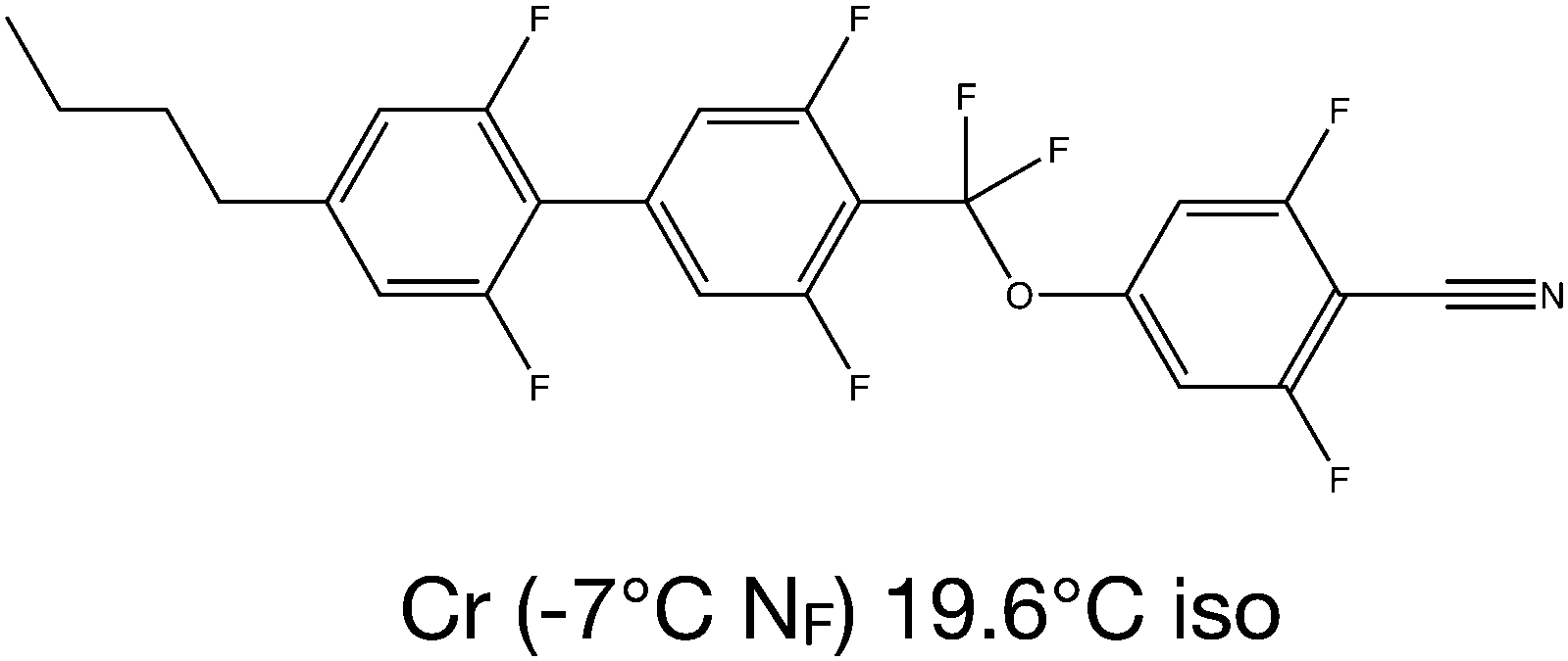 | ||
| Fig. 1 Chemical structure of the investigated mesogen. | ||
The mechanical and magneto-optical properties were studied by observing the Fréedericksz transition (FT) in a magnetic field. The FT was studied through the measurement of the optical transmission between two crossed polarising prisms (Thorlabs). For the magnetic Fréedericksz transition, the cell was placed between two Helmholtz coils. For studying the splay transition, the magnetic field was aligned perpendicular to the cell (Fig. 2a). In this geometry, the critical field is determined by a splay elastic constant K11. To distinguish the hypothetical elastic constant unaffected by the polar structure from the measured one, we designated the latter by Keff11. To determine a twist elastic constant K22, the cell was placed parallel to the magnetic field and perpendicular to the rubbing direction of the aligning layer (Fig. 2b). The magnetic field was generated by a pair of electromagnets with a maximal magnetic flux density of 650 mT. Measurements of the optical transmission were obtained upon an increasing magnetic field of up to 650 mT with a step of 10 mT and 15 s waiting time between the field application and the data acquisition. The critical field for the magnetic Fréedericksz transition was also determined using dielectric spectroscopy. Dielectric measurements were obtained employing an Alpha-N frequency response analyser (Novocontrol). The isothermal curves of the dielectric permittivity as a function of frequency were acquired between 0.1 Hz and 1 MHz using an alternating field of Vrms = 0.1 V. Successively increasing values of the magnetic field were applied, varying from zero to 1.4 T in steps of roughly 60 mT. For the evaluation of the critical magnetic field for the Fréedericksz transition, the frequency of f = 110 Hz was used.
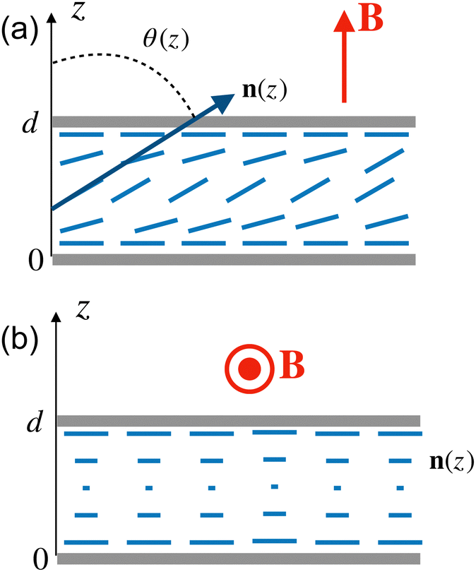 | ||
| Fig. 2 Liquid crystal cells: (a) splay configuration with a magnetic field applied perpendicular to the substrate and the unperturbed director n, and (b) twist configuration with a magnetic field applied parallel to the substrate and perpendicular to the director n. | ||
The 3D structure of the director field and the polarisation were investigated using polarising confocal laser scanning microscopy (Leica TCS SP8, CLSM). The samples were doped with 0.01 wt% of a dichroic dye (N,N′-bis(2,5-di-tertbutylphenyl)-3,4,9,10-perylenedicarboximide (BTBP), Sigma-Aldrich) to visualise the director orientation and excited using a laser light at λex = 488 nm. The generation of the optical second harmonic (SHG) was measured using the multiphoton laser of a confocal microscope. A tunable IR laser (λex = 880 nm) was used as a fundamental light beam.
3 Results
3.1 Polarisation switching in the NF phase
Upon cooling of the isotropic liquid below T = 20.6 °C, the nematic phase nucleates in the form of birefringent droplets, as can be seen in Fig. 3a, which coalesce into a nearly uniform texture in an LC cell with the planar alignment as shown in Fig. 3b. The optical texture exhibits typical for nematic director fluctuations, and the birefringence only weakly depends on the temperature (Fig. 4).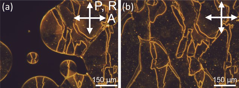 | ||
| Fig. 3 Optical microscopy textures of the studied compound taken between crossed polarisers in a 30 μm planar cell at (a) 20.2 °C and (b) 18 °C. | ||
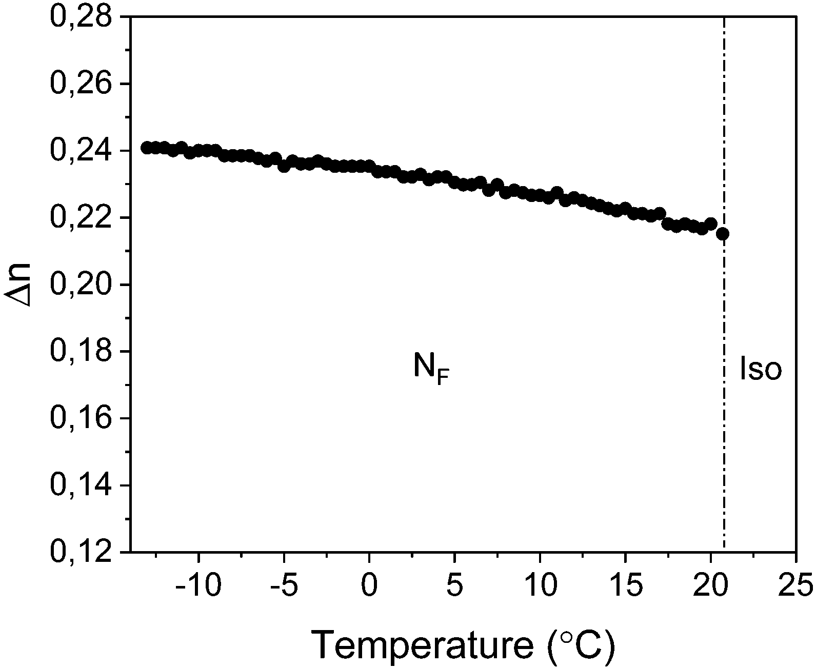 | ||
| Fig. 4 Temperature dependence of the birefringence of the investigated mesogen measured in a 5 μm planar cell. | ||
Bistable switching in an electric field is one of the essential features of ferroelectrics, which distinguishes them from other polar materials.31 Polarisation reversal drives the electric switching in liquid crystals, which is often accompanied by the reorientation of the optical axis and/or birefringence change (optical switching). The polarisation reversal in a ferroelectric sample confined in a capacitor cell results in the current transient, which is indicative of the ferro- or antiferroelectric character of the switching.32Fig. 5a shows the current transients recorded in the NF phase at T = 13 °C at various amplitudes of a triangular-wave voltage applied to the test cell. At small amplitudes, we observe a single current peak centred at a voltage Vth of 0.16 V μm. As the amplitude increases, a second broad peak appears at high fields. Multiple peaks in the current transients have been observed in various LC systems.33–37 They can be attributed to the antiferro- or ferrielectric types of order, complex anchoring conditions, the trapping of charges in the topological defects and dislocations, and ionic impurities. The ionic contribution becomes dominant at high fields resulting in a broad current peak.
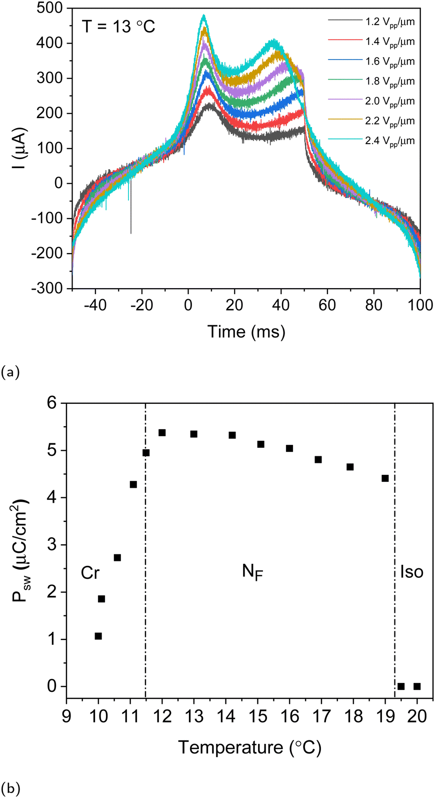 | ||
| Fig. 5 Polarisation switching in a planar 30 mm cell: (a) current transients recorded at T = 13 °C at various amplitudes of the triangular-wave field. (b) Temperature dependence of the switching polarisation Psw measured at a frequency f of 5 Hz and an amplitude of 0.7 V μm−1. | ||
The switching polarisation Psw estimated from the area under the current reversal peak is plotted in Fig. 5b. Psw is remarkably high, reaching almost 6 μC cm−2. Switching polarisation can be considered as an estimation of the spontaneous polarisation of the liquid crystal.32 A discontinuous increase of Psw upon the isotropic–NF transition reflects the first-order character of the transition. The polarisation only slightly increases upon the decreasing temperature. Below T = 11.5 °C, however, there is a continuous decrease in the polarisation which is driven by the slow crystallisation kinetics of the monotropic NF phase.
3.2 Nonlinear optical response
The generation of the optical second harmonic (SHG) is a widely used technique to establish the polar order in crystals and liquid crystals.38–40 In contrast to the switching current measurements, it does not require poling of the polarisation and application of external fields. SHG results from the nonlinear interaction between the light and the media, which leads to the energy transfer from the primary beam to the SH beam. The phase symmetry determines the allowed components of the second order optical susceptibility tensor and forbids SHG in the phases with the inversion symmetry.To study the spatially resolved generation of the SH, we employ the SHG microscopy technique, where an IR laser (880 nm) is used as the light source in the confocal scanning microscope. The microscopic textures in untreated glass slides are shown in Fig. 6a between crossed polarisers and in Fig. 6b the corresponding SHG texture.
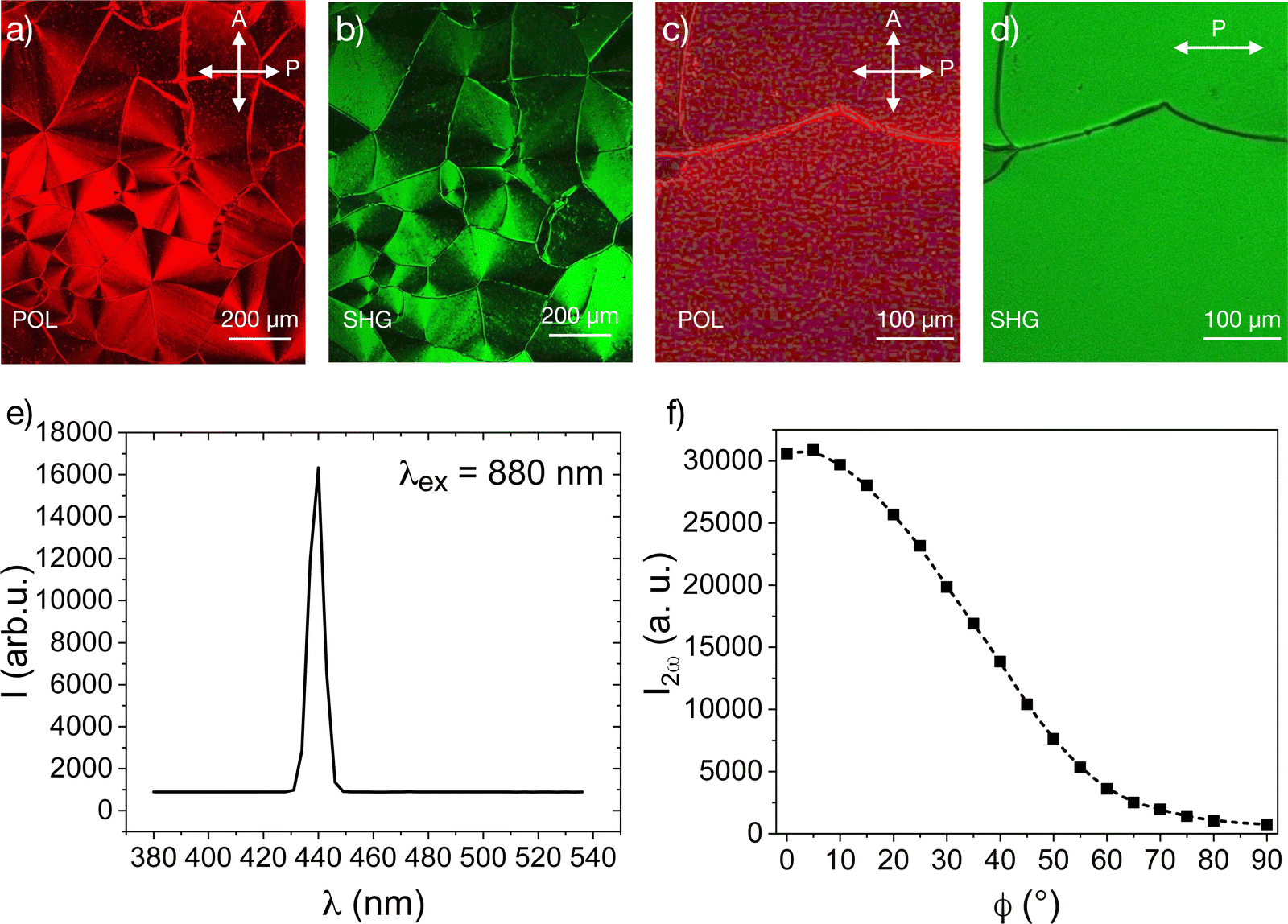 | ||
| Fig. 6 (a) Polarisation microscopy image taken at 18.9 °C between a pair of untreated glass plates. (b) SHG microscopy image of the texture in (a). (c and d) POM and SHG images in a cell with the rubbed polyimide aligning layer, respectively. (e) The spectrum of the SHG signal taken with an excitation at λex = 880 nm at 19.0 °C. (f) The angular dependence of the SHG signal in a homogeneously aligned sample at 19.4 °C. | ||
To distinguish SHG from the multiphoton fluorescence with a broad spectrum, we recorded the transmission spectrum of the sample under 880 nm excitation (Fig. 6c). The spectrum features only a single resolved peak centred at 440 nm, suggesting that our sample is SHG active. An extraordinary large SHG signal occurs spontaneously, without any applied external field, confirming the polarity of the ground state of the nematic phase.
The angular dependence of the SHG polarisation in Fig. 6c established the relationship between the polar and the nematic directors. The highest intensity of the SHG signal corresponds to the polarisation along the nematic director. The temperature dependence of the SHG signal is shown in Fig. 7. As the temperature decreases, the signal increases by several orders of magnitude.
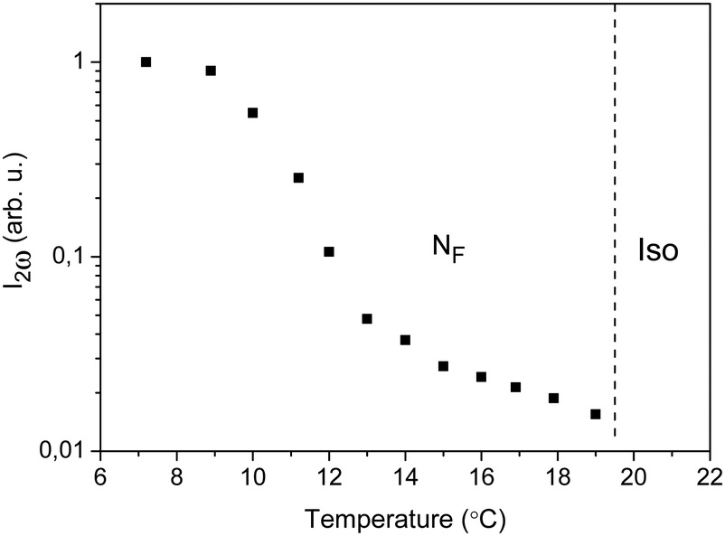 | ||
| Fig. 7 Temperature dependence of the SHG signal measured in untreated glass slides. | ||
The spontaneous polarity can be very well demonstrated by the confocal SHG microscopy images of sessile droplets on a glass substrate (Fig. 8). Between the crossed polarisers, the optical image features an extinction cross with a disclination line in the centre. The director orientation can be determined from the angular dependence of the absorption by the dichroic dye dissolved in the liquid crystal (Fig. 8b and d). The intensity distribution suggests the tangential alignment of the director arranged into concentric rings. The intensity distribution confirms our assumption that the polarisation is parallel to the nematic director.
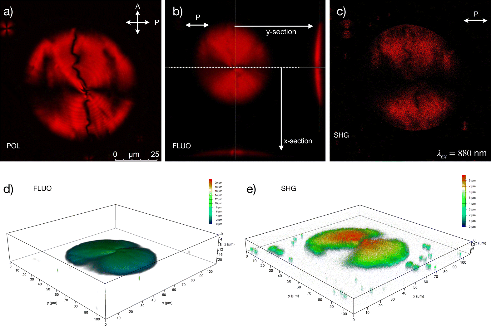 | ||
| Fig. 8 Sessile droplets imaged by confocal microscopy: (a) transmission POM image taken in a monochromatic light, (b) three orthogonal section of the confocal microscopy image (fluorescence), (c) a horizontal section of the confocal SHG image, (d) 3D reconstruction of the sessile droplet in (b) as observed in the confocal polarising microscopy image, and (e) 3D reconstruction of the confocal SHG image of the droplet in (c). | ||
The bistable character of the polarisation switching is evident from the field-dependent SHG measurements in the cells with in-plane electrodes (IPS). The signal I2ω(E) exhibits a distinct hysteresis behaviour (Fig. 9). A coercive field of the opposite polarity is required to suppress the spontaneous signal.
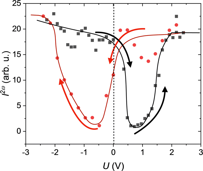 | ||
| Fig. 9 Hysteresis-type field-dependence of the SHG signal I2ω recorded at T = 15 °C (the lines are guide for the eye). | ||
3.3 Fréederiksz transition
In contrast to the electric Fréederiksz transition (FT), the magnetic FT allows a much more straightforward interpretation since the magnetic field does not directly couple to the electric polarisation or charges. The critical magnetic field is determined by the diamagnetic anisotropy χa and the Frank elastic constants Kii (splay, twist or bend). Since this compound does not exhibit a regular nematic phase, we cannot estimate χa = χ‖ − χ⊥ from the simultaneous measurements of the critical magnetic and electric fields. Instead, we use the increment system developed by Flygare et al.41 to calculate χa from the chemical structure of the mesogen. Aromatic moieties give the largest contribution to diamagnetic susceptibility. We assume that the main axis of the mesogen is given by the tetrafluoro-biphenyl part, and the difluorobenzonitrile head group can freely rotate around the main axis at an angle of 65.3°. From these assumptions, we estimate χa = 1.607 × 10⁻⁶. The Fréederiksz transition was studied using the measurements of the optical transmission, and the critical field μ0Hc was determined from the extrapolation of the I(H) curves. In the splay geometry, the critical field is about 580 mT in a 30 μm thick cell, which is close to the limit of our measuring magnet. The critical field in the splay geometry was also investigated through dielectric spectroscopy measurements in a 30 μm planar cell. The acquired isothermal curves of the real part of the dielectric permittivity versus frequency are presented in Fig. 10a, for increasing values of the applied magnetic field. Although the compound exhibits very high values of dielectric permittivity, this is not the case for the dielectric anisotropy, which is two orders of magnitude smaller. It should be noted that, within the NF phase, the values of the dielectric permittivity measured in cells with polyimide aligning layers are effectively smaller due to the capacitance of the aligning layers.42 However, this phenomenon does not affect the dielectric anisotropy and the determination of the critical field of the splay FT. The detailed investigation of the dielectric response of the compound is out of the scope of the present work. The critical magnetic field of the splay Fréederiksz transition was determined at f = 110 Hz, away from any relaxation mode. The field dependence of the dielectric constant was made at 18 °C, as shown in Fig. 10b. The values of the critical magnetic field determined from optical transmission measurements correspond to the effective splay elastic constant Keff11 as high as 36 pN. Keff11 shows hardly any temperature dependence, as shown in Fig. 11. At the same time, the twist elastic constant K22 appears significantly smaller and amounts to only 6.4 pN.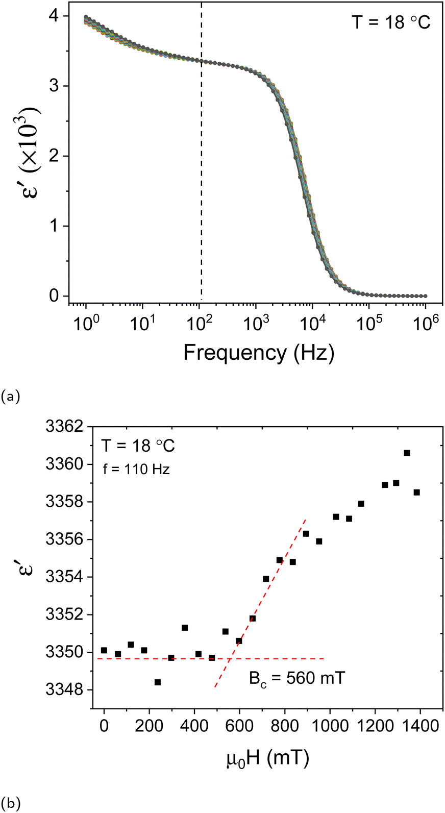 | ||
| Fig. 10 (a) Isothermal curves of the dielectric permittivity as a function of frequency at 18.0 °C measured in a 30 μm cell with polyimide rubbed substrates measured in the external magnetic field ranging from 0 to 1.4 T with a step of 60 mT. (b) Magnetic field dependence of the real part of the dielectric permittivity at f = 110 Hz. | ||
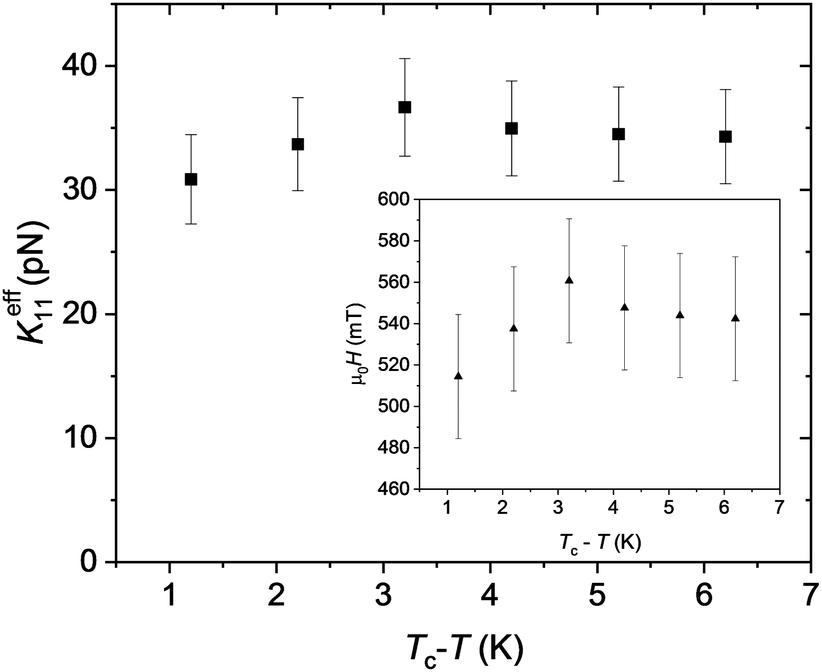 | ||
| Fig. 11 Temperature dependence of the splay elastic constant measured in a 25 μm cell with polyimide rubbed substrates. The critical magnetic field μ0Hc is given in the inset. | ||
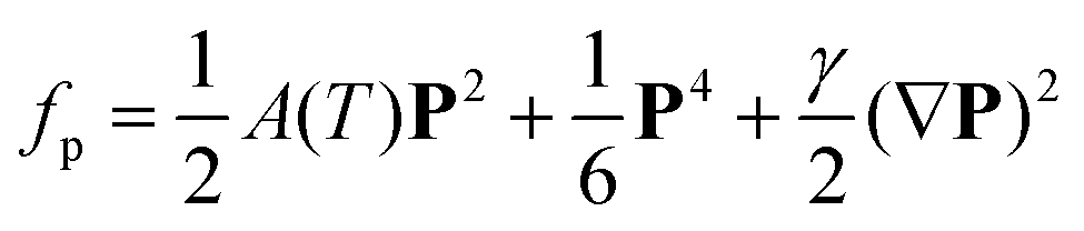
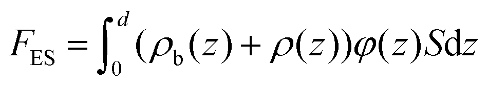
To elucidate the effect of the spontaneous polarisation on the mechanical properties of the ferroelectric liquid crystal, we need to consider the free energy of the system. In the theory of ferroelectrics, the polarisation-dependent contribution to the field-independent part of the Landau free energy density is given by43
 | (1) |
In our description, we consider a nematic liquid crystal confined between two parallel glass substrates with a uniformly aligned nematic director parallel to the substrate (Fig. 2a). The deflection angle of the director from the substrate normal (z-direction) is designated by θ(z). The total free energy of the cell is the sum of the Frank–Oseen energy of the director deformation FFO, the magnetic energy Fm, and the electrostatic energy Fes induced by the director deformation inside the cell:
| F = FFO + Fm + Fes | (2) |
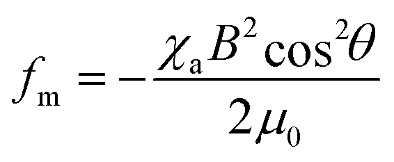
The polar (ferroelectric) structure of the NF phase is marked by the spontaneous polarisation Ps aligned parallel to the nematic director n, Ps = Psn. A magnetic field is applied in the direction perpendicular to n exerting a magnetic torque on the director (Fig. 2a). In the following, we will derive the equilibrium conditions for the nematic director in a magnetic field using the minimisation of the free energy. For the electrostatic contribution, we will solve the Poisson equation to obtain the electric potential depending on the director deformation.
In one-constant approximation, the expressions for the Frank–Oseen energy density is given by
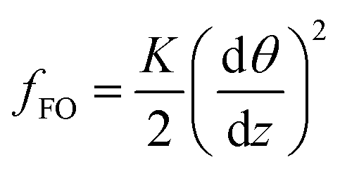 | (3) |
 | (4) |
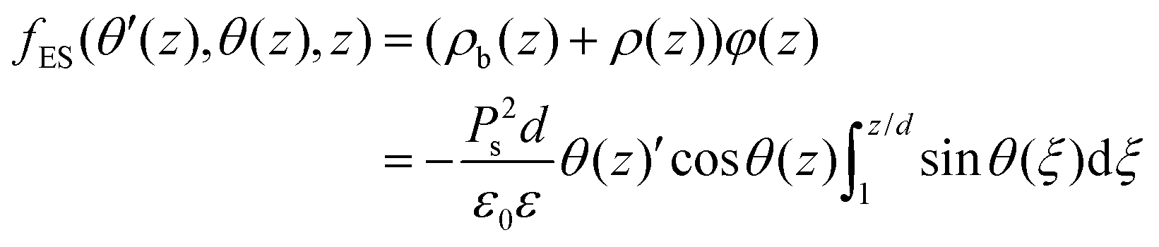
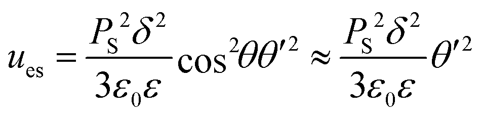
The Fréederiksz transition in the splay geometry is accompanied by the formation of the director splay areas near the substrate. The polarisation becomes nonuniform exhibiting a dependence on the vertical coordinate z with a vertical component Ps,z = Pssinθ(z) see eqn (5), Fig. 2a, where θ(z) is the angle between the polarisation P and the cell normal. The polarisation splay results in a nonuniform distribution of the bound charges
| ρb = −∇·P = Pscosθ·θ′ | (5) |
This charge distribution determines the electric potential φ(z) and can be obtained from the solution of the Poisson equation
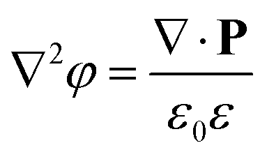 | (6) |
Substituting Ps,z = Pssinθ(z) into eqn (6), we obtain φ′′(z) = (ε0ε)−1Pscosθ·θ′ yielding the solution for the case of the constant charge (open circuit)
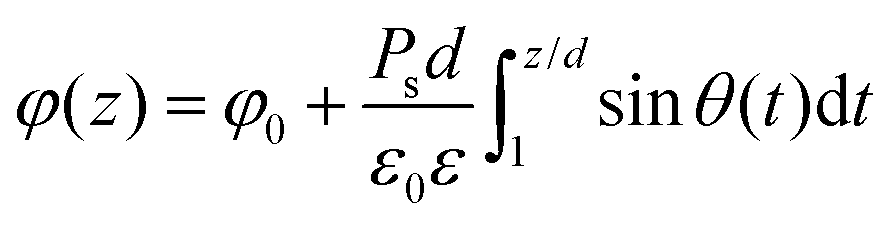 | (7) |
The electrostatic contribution is given by the term
 | (8) |
Neglecting the free charges in the system and substituting the solution for the potential φ(z), we obtain the energy density
 | (9) |
The equilibrium equations can be obtained for arbitary dependence θ = θ(z) form using variation principles. The net energy is given by the sum of the elastic, magnetic and electric contributions:
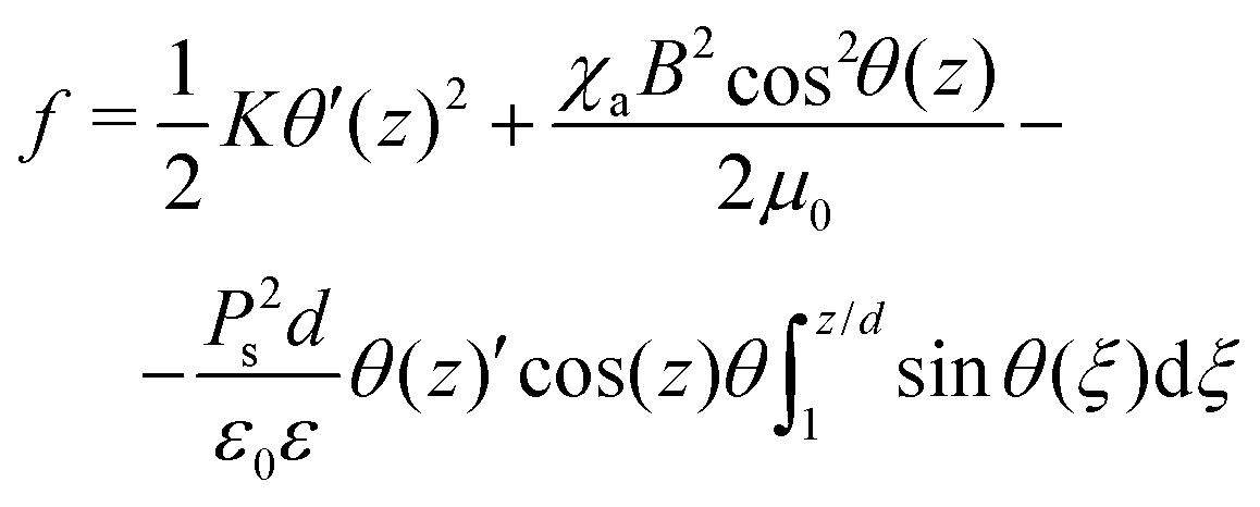 | (10) |
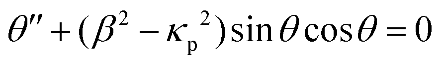
The equilibrium condition is described by
δ![[F with combining tilde]](https://www.rsc.org/images/entities/i_char_0046_0303.gif) = 0 = 0 | (11) |
is given by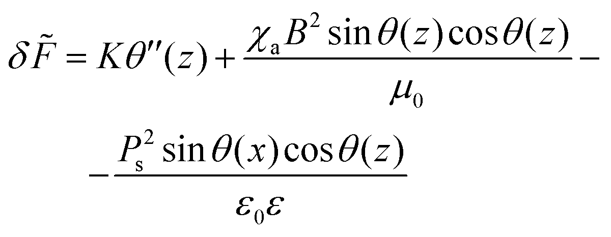 | (12) |
This equation can be converted to a dimensionless form by introducing the characteristic field 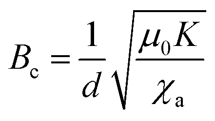 , and the dimensionless field β = B/Bc. The contribution of the spontaneous polarisation term is scaled by the parameter
 | (13) |
 | (14) |
The Fréederiksz transition sets off when β2 − κp2 = π2 or the external magnetic field satisfies
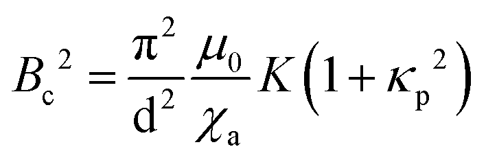 | (15) |
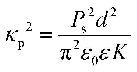
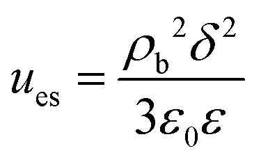
In the experiment, we determine the effective constant Keff = K(1 + κp2), with K = K11 (at the instability onset) for the splay geometry Fig. 2a). The elastic constant K11 becomes effectively rescaled by the polarisation contribution. The characteristic parameter κp determines the scale of the polarisation–splay effect. To estimate the value of κp, we take the values of the switching polarisation as Ps = 6 μC cm−2, a typical value for the effective elastic constant K = 10 pN, ε = 2 × 10⁴, d = 30 μm, we estimate κp2 ≈ 1.85 × 10⁵. This is a very large value, which appears to contradict the experimental observations. In the twist geometry (Fig. 2b), however, K = K22, the twist elastic constant and the polarisation charges do not contribute to the free energy. One possibility to explain the discrepancy between the experimental (factor 10) and the theoretical values (factor 105) could be an overestimation of the spontaneous polarisation. The value Ps = 6 μC cm−2 is large even for some solid ferroelectrics.46 The current–response measurements of Ps can be strongly biased by the induced polarisation due to the ionic contributions and the induced polarisation due to a very high dielectric permittivity.33,34 In smectic LCs, materials exhibiting a high switching polarisation become antiferroelectrics rather than ferroelectrics.31 A more reasonable explanation of the reduced stiffening of K11 is the screening of the electrostatic interactions. Electrostatic screening can be accounted assuming that the screening length δ restricts the interaction range. For a low impurity concentration, we can take δ in order of few hundred nanometres. We consider a uniform splay deformation in a slab of thickness δ. The electric field is equivalent to the field of a uniformly charged slab 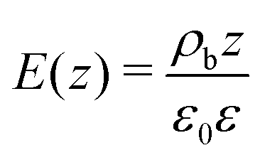 , and the corresponding energy density
 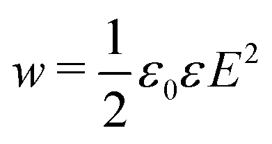 , where ε is the dielectric permittivity in the high-frequency limit. Integrating the energy density over the thickness of the slab, we obtain the electrostatic energy of the slab
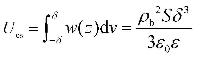 | (16) |
 | (17) |
Substituting the expression for ρ, we obtain
 | (18) |
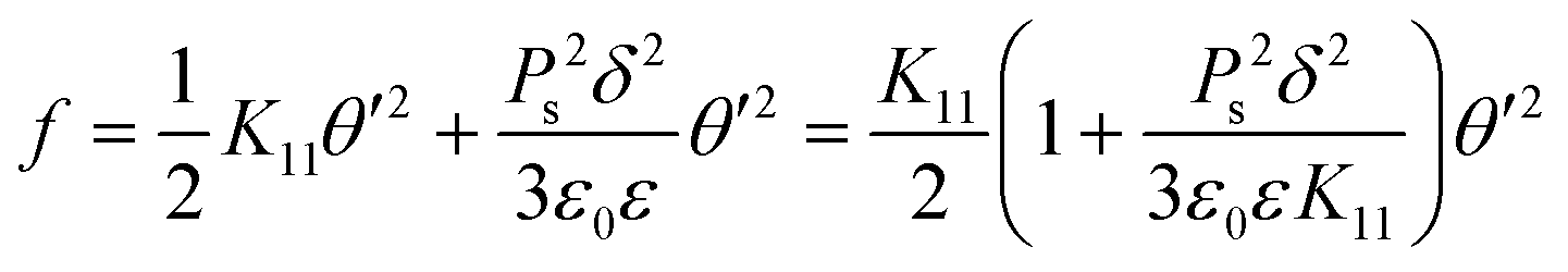 | (19) |
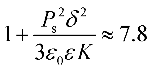
The expression in the brackets is the effective scaling factor of the splay elastic constant modified by the electrostatic contribution. Substituting typical values for the screening length for the low concentration of the ionic impurities δ ≈ 100 nm,47 we obtain the estimation of the factor
 | (20) |
This value is much closer to the experimentally observed increase of the elastic constant. The scaling factor is similar to the parameter κp and differs only by a scaling factor of the order of unity and the length scale. Screening results in the crossover of the length scale from the cell thickness d to the much smaller screening length δ.
4 Conclusions
We investigated the polar and magneto-optical behaviour of the room-temperature ferroelectric nematic phase with high switching polarisation. The first order isotropic-NF transition is marked by a strong spontaneous nonlinear optical response (SHG). The polar axis is aligned along the nematic director. We show that the splay elastic constant exceeds the twist constant considerably with K11/K22 ≈ 6. In a comparable mesogen such as 5CB, for example, this ratio is about 2. Another important finding is that the absolute value of K11 above 30 pN for a compound having such a low isotropic-(ferro)nematic transition temperature is very high. For comparison, K22 is in the order of 6.4 pN at room temperature. High spontaneous polarisation can be responsible for the stiffening of the splay elastic constant since the polarisation splay increases the electrostatic energy of the system. At the same time, the twist deformation remains unaffected by the electrostatics. The stiffening of K11 is restricted by the screening effects.Conflicts of interest
There are no conflicts to declare.Acknowledgements
The authors acknowledge Panagiota K. Karahaliou and Alexandros G. Vanakaras (University of Patras, Greece), Nerea Sebastián, Alenka Mertelj (Jožef Stefan Institute, Slovenia), and Nataša Vaupotič (University of Maribor) for fruitful discussions and Deutsche Forschungsgemeinschaft (Project ER467/8-3) for the financial support. E. Z. acknowledges financial support from the Hellenic Foundation for Research and Innovation (HFRI PhD Fellowship grant, Fellowship Number: 809096).Notes and references
- P. M. Chaikin and T. C. Lubensky, Principles of Condensed Matter Physics, Cambridge University Press, 1995 Search PubMed.
- P. Oswald and P. Pieranski, Nematic and cholesteric liquid crystals: concepts and physical properties illustrated by experiments, Taylor & Francis/CRC Press, 2005 Search PubMed.
- K. Nayani, Y.-K. Kim and N. L. Abbott, Nat. Mater., 2018, 17, 14–15 CrossRef CAS PubMed.
- T. C. Lubensky, A. B. Harris, R. D. Kamien and G. Yan, Ferroelectrics, 1998, 212, 1–20 CrossRef CAS.
- J. Yang, W. Zhao, W. He, Z. Yang, D. Wang and H. Cao, J. Mater. Chem. C, 2019, 7, 13352–13366 RSC.
- T. C. Lubensky and L. Radzihovsky, Phys. Rev. E, 2002, 66, 031704 CrossRef CAS PubMed.
- H. R. Brand, H. Pleiner and F. Ziebert, Phys. Rev. E, 2006, 74, 021713 CrossRef PubMed.
- H. R. Brand, H. Pleiner and P. Cladis, Physica A, 2005, 351, 189–197 CrossRef.
- H. Pleiner and H. R. Brand, EPL, 1989, 9, 243–249 CrossRef CAS.
- R. J. Mandle, S. J. Cowling and J. W. Goodby, Phys. Chem. Chem. Phys., 2017, 19, 11429–11435 RSC.
- R. J. Mandle, S. J. Cowling and J. W. Goodby, Chem. – Eur. J., 2017, 23, 14554–14562 CrossRef CAS PubMed.
- H. Nishikawa, K. Shiroshita, H. Higuchi, Y. Okumura, Y. Haseba, S.-I. Yamamoto, K. Sago and H. Kikuchi, Adv. Mater., 2017, 29, 1702354 CrossRef PubMed.
- A. Mertelj, L. Cmok, N. Sebastián, R. J. Mandle, R. R. Parker, A. C. Whitwood, J. W. Goodby and M. Čopič, Phys. Rev. X, 2018, 8, 041025 CAS.
- N. Sebastián, R. J. Mandle, A. Petelin, A. Eremin and A. Mertelj, Liq. Cryst., 2021, 48, 2055–2071 CrossRef.
- R. J. Mandle, N. Sebastián, J. Martinez-Perdiguero and A. Mertelj, Nat. Commun., 2021, 12, 4962 CrossRef CAS PubMed.
- X. Chen, E. Korblova, D. Dong, X. Wei, R. Shao, L. Radzihovsky, M. A. Glaser, J. E. Maclennan, D. Bedrov, D. M. Walba and N. A. Clark, Proc. Natl. Acad. Sci. U. S. A., 2020, 117, 14021–14031 CrossRef CAS PubMed.
- A. Manabe, M. Bremer and M. Kraska, Liq. Cryst., 2021, 48, 1–8 CrossRef.
- M. P. Rosseto and J. V. Selinger, Phys. Rev. E, 2020, 101, 052707 CrossRef CAS PubMed.
- S. Dhakal and J. V. Selinger, Phys. Rev. E, 2010, 81, 031704 CrossRef PubMed.
- J. V. Selinger, Annu. Rev. Condens. Matter Phys., 2021, 13, 1–23 Search PubMed.
- N. V. Madhusudana, Phys. Rev. E, 2021, 104, 014704 CrossRef CAS PubMed.
- K. Takae and H. Tanaka, Proc. Natl. Acad. Sci. U. S. A., 2018, 115, 9917–9922 CrossRef CAS PubMed.
- E. I. Kats, Phys. Rev. E, 2021, 103, 012704 CrossRef CAS PubMed.
- A. Khachaturyan, J. Phys. Chem. Solids, 1975, 36, 1055–1061 CrossRef CAS.
- C. Feng, R. Saha, E. Korblova, D. Walba, S. N. Sprunt and A. Jákli, Adv. Opt. Mater., 2021, 9, 2101230 CrossRef CAS.
- M. Šarabot, I. Muševič and R. Blinc, Phys. Rev. E, 1998, 57, 6725–6731 CrossRef.
- M. Čopič, J. E. Maclennan and N. A. Clark, Phys. Rev. E, 2002, 65, 021708 CrossRef PubMed.
- M. Nakagawa and T. Akahane, J. Phys. Soc. Jpn., 1986, 55, 1516–1522 CrossRef CAS.
- H. J. Deuling, Mol. Cryst. Liq. Cryst., 2007, 19, 123–131 CrossRef.
- A. D. Oskirko, S. V. Ul’yanov and A. Y. Val’kov, Phys. Rev. E, 2018, 98, 012702 CrossRef CAS PubMed.
- S. T. Lagerwall, Ferroelectric and Antiferroelectric Liquid Crystals, Wiley-VCH, 1999 Search PubMed.
- K. Miyasato, S. Abe, H. Takezoe, F. Atsuo and E. Kuze, Jpn. J. Appl. Phys., 1983, 22, L661–L663 CrossRef.
- M. L. Blinov, V. A. Baikalov, I. M. Barnik, L. A. Beresnev, E. P. Pozhidayev and S. V. Yablonsky, Liq. Cryst., 1987, 2, 121–130 CrossRef.
- M. I. Barnik, L. M. Blinov, N. M. Shtykov, S. P. Palto, G. Pelzl and W. Weissflog, Liq. Cryst., 2002, 29, 597–603 CrossRef CAS.
- Y. Shen, T. Gong, R. Shao, E. Korblova, J. E. Maclennan, D. Walba and N. Clark, Phys. Rev. E, 2011, 84, 020701 CrossRef PubMed.
- S. Stern, R. Stannarius, A. Eremin and W. Weissflog, Soft Matter, 2009, 5, 4136–4140 RSC.
- S. Findeisen-Tandel, M. Schröder, G. Pelzl, U. Baumeister, W. Weissflog, S. Stern, A. Nemes, R. Stannarius and A. Eremin, Eur. Phys. J. E: Soft Matter Biol. Phys., 2008, 25, 395–402 CrossRef CAS PubMed.
- R. Macdonald, F. Kentischer, P. Warnick and G. Heppke, Phys. Rev. Lett., 1998, 81, 4408–4411 CrossRef CAS.
- F. Araoka, J. Thisayukta, K. Ishikawa, J. Watanabe and H. Takezoe, Phys. Rev. E, 2002, 66, 021705 CrossRef PubMed.
- C. L. Folcia, J. Ortega, R. Vidal, T. Sierra and J. Etxebarria, Liq. Cryst., 2022, 1–8 Search PubMed.
- W. H. Flygare, Chem. Rev., 1974, 74, 653–687 CrossRef CAS.
- S. Brown, E. Cruickshank, J. M. D. Storey, C. T. Imrie, D. Pociecha, M. Majewska, A. Makal and E. Gorecka, Chem. Phys. Chem., 2021, 22, 2506–2510 CrossRef CAS PubMed.
- M. Marvan and J. Fousek, Phys. Status Solidi B, 1998, 208, 523–531 CrossRef CAS.
- N. Sebastián, M. Čopič and A. Mertelj, Phys. Rev. E, 2022, 106, 021001 CrossRef PubMed.
- S. M. Shamid, S. Dhakal and J. V. Selinger, Phys. Rev. E, 2013, 87, 052503–052512 CrossRef PubMed.
- N. Izyumskaya, Y. Alivov and H. Morkoç, Crit. Rev. Solid State Mater. Sci., 2009, 34, 89–179 CrossRef CAS.
- C. Dascalu, R. Atasiei and M. Raicopol, UPB Sci. Bull. Ser., Ser. A, 2009, 71, 89–94 Search PubMed.
Footnote |
| † Current address: Im Freiacker 14, 64625 Bensheim, Germany. |
| This journal is © The Royal Society of Chemistry 2022 |