DOI:
10.1039/D2SM00942K
(Paper)
Soft Matter, 2022,
18, 7051-7063
Chemically active filaments: analysis and extensions of slender phoretic theory
Received
14th July 2022
, Accepted 18th August 2022
First published on 23rd August 2022
Abstract
Autophoretic microswimmers self-propel via surface interactions with a surrounding solute fuel. Chemically-active filaments are an exciting new microswimmer design that augments traditional autophoretic microswimmers, such as spherical Janus particles, with extra functionality inherent to their slender filament geometry. Slender Phoretic Theory (SPT) was developed by Katsamba et al. to analyse the dynamics of chemically-active filaments with arbitrary three-dimensional shape and chemical patterning. SPT provides a line integral solution for the solute concentration field and slip velocity on the filament surface. In this work, we exploit the generality of SPT to calculate a number of new, non-trivial analytical solutions for slender autophoretic microswimmers, including a general series solution for phoretic filaments with arbitrary geometry and surface chemistry, a universal solution for filaments with a straight centreline, and explicit solutions for some canonical shapes useful for practical applications and benchmarking numerical code. Many common autophoretic particle designs include discrete jumps in surface chemistry; here we extend our SPT to handle such discontinuities, showing that they are regularised by a boundary layer around the jump. Since our underlying framework is linear, combinations of our results provide a library of analytic solutions that will allow researchers to probe the interplay of activity patterning and shape.
1 Introduction
Chemically active filaments are an exciting new category of artificial microswimmers. These slender bodies use a surrounding solute as fuel to self-propel via chemical interactions between the filament surface and the solute.2,3 Surface chemical reactions locally generate or deplete the solute, and any resulting concentration gradients induce a slip flow close to the filament that pushes it through the surrounding viscous fluid.4,5 Swimmers that use this type of mechanism to move are called phoretic swimmers, and they have significant potential for use in biomedical6 and microfluidic settings.7
Phoretic swimmers are typically spheroidal particles.8 However, recent technological developments in microscale manufacturing techniques mean that it is now feasible to create phoretic microswimmers with non-trivial geometries.9 This opens up a whole new world of physically realisable microscale designs that are yet to be fully explored. One common structure observed in nature are slender filaments, which are the primary method of propulsion at the microscale (e.g. flagella and cilia).10 Phoretic slender structures, or chemically active filaments, have the potential for more interesting behaviour than particles, since there is a separation of scales into long and thin directions that increases the significance of geometry. This gives slender phoretic filaments an additional dimension of control over previous designs; surface properties can be more easily controlled along the filament's length, allowing for regions of the filament with different local flow behaviours, and smart/soft materials can be incorporated into the filament design to allow controlled shape change and responsivity.11
In previous recent work, Slender Phoretic Theory (SPT)1 was derived for phoretic filaments of arbitrary 3D centreline, cross-sectional radius, and chemical patterning by exploiting a matched-asymptotic expansion from a boundary integral representation of Laplace's equation in Stokes flows.12 This approach asymptotically reduces the phoretic problem from explicitly solving a boundary value problem—or surface integrals, if numerically solving using boundary element methods (BEM)13—to simply evaluating integrals along the filament centreline to determine the key phoretic properties. These results from SPT can be combined with other slender body theories for Stokes flows to then determine the swimming behaviour.12
Many other slender body theories exist for specific applications and designs of phoretic filaments. Examples include the electrophoretic propulsion of slender straight rods with varying cross-sections,14 and autophoretic particles with axisymmetric chemical activity15 or more complex reaction kinetics.16 However, SPT is ideally designed to deal with phoretic propulsion of slender filaments with arbitrary three-dimensional shapes and arbitrary surface activities.
In previous work on slender phoretic filaments,1 the integrals arising from SPT were calculated numerically, and compared to BEM simulations. However, purely analytical results can provide physical intuition, enhanced understanding of dynamics as parameters are varied, and validation for numerical codes. Additionally, analytical results are computationally faster, asymptotically exact, and can provide an important component for fast simulation of multi-particle suspensions.17
In this paper, we derive analytical solutions to SPT. This is both in terms of extensions to the theory, as well as specific applicable examples. We start in Section 2 with a summary of the results of SPT. In Section 3 we consider the general result for an arbitrary geometry with non-axisymmetric activity, so that azimuthal variation around the centreline is allowed, and we show that the surface concentration profile can be written as the sum of an axisymmetric activity with the same azimuthally averaged profile and a Fourier series of the azimuthal variation of the activity around the centreline. In Section 4, we show that the solutions for axisymmetric straight filaments can be derived in terms of a Legendre polynomial expansion of the activity, and hence derive a universal solution for straight rods with arbitrary activity in terms of Legendre polynomials and Fourier modes. In Section 5, we give some analytical results for a few basic geometries and common activities. Finally, in Section 6, we consider an issue regarding sudden jumps in activity, such as in the canonical example of Janus swimmers (which are half active and half inert),18 and we show that any apparent discontinuity is regularised by a small boundary layer close to the jump, before discussing the results in Section 7.
2 Review of slender phoretic theory
2.1 General phoretic swimmers
We begin by briefly outlining the key equations that govern autophoretic propulsion. We consider the limit of zero Péclet number, where advection of the solute in the bulk fluid is negligible compared to diffusion (valid for sufficiently small swimmers),8,19 and neglect electrokinetic effects.20,21 Under these conditions, the concentration of solute in the fluid surrounding the swimmer (which we assume to be infinite in extent), c(x), obeys Laplace's equationOn the swimmer's surface, the solute is generated or depleted by the chemical reactions, and a slip velocity, vslip, is generated due to surface concentration gradients| |  | (2) |
| |  | (3) |
Here, nf is the normal to the swimmer's surface pointing into the fluid;  is the activity on the surface, which is the rate at which the solute is released there (or depleted when
  ); and
  is the mobility, which relates the surface concentration gradients to the slip velocity. Both the activity and mobility are given properties of the surface, and may vary over the swimmer's surface; swimmers with the same geometry and different patterning of activity and/or mobility will behave differently. For example, a wide range of different swimming behaviours can be produced by varying the placement of patches of activity and mobility on spheres.22
Given the geometry, activity and mobility of the swimmer, the Laplace equation, eqn (1), can be solved subject to eqn (2) on the swimmer's surface to determine c(x) everywhere, and then the slip velocity calculated using eqn (3), as shown in the flow diagram of Fig. 1. The subsequent fluid flow and swimming can then be determined using the Stokes flow equations with the slip velocity as a boundary condition. A common method of solving these equations for a general swimmer shape is to use the Boundary Element Method.13,23,24 However, for certain basic designs of phoretic swimmer, analytical progress can be made.8,25
 |
| | Fig. 1 A flow diagram demonstrating how the emergent swimming behaviour of phoretic filaments arises from the underlying physics, in the limit of zero Péclet number and for solute neutral diffusiophoresis. Slender Phoretic Theory, and this paper, covers aspects to the left of the vertical dashed line for filaments with arbitrary 3D centrelines and arbitrary chemical patterning. Fluid dynamics and swimming speed may then be calculated via slender body theories for Stokes flows.12 | |
2.2 Slender phoretic filaments
We now briefly summarise the key results of SPT.1 The geometry of a slender filament is illustrated in Fig. 2. We consider a slender swimmer with points on its surface given (in dimensionless terms) by the position vector| | | S(s,θ) = r(s) + ερ(s)êρ(s,θ), | (4) |
parametrised by the arclength s ∈ [−1,1] along the centreline, r(s), and the azimuthal angle θ around the centreline. The dimensionless cross-sectional radius ρ(s) obeys 0 < ρ(s) < 1. The radially-outward pointing unit vector êρ(s,θ) is defined as êρ(s,θ) = cos![[thin space (1/6-em)]](https://www.rsc.org/images/entities/char_2009.gif) Θ(s,θ)
Θ(s,θ)![[n with combining circumflex]](https://www.rsc.org/images/entities/b_char_006e_0302.gif) (s) + sin
(s) + sin![[thin space (1/6-em)]](https://www.rsc.org/images/entities/char_2009.gif) Θ(s,θ)
Θ(s,θ)![[b with combining circumflex]](https://www.rsc.org/images/entities/b_char_0062_0302.gif) (s) with Θ(s,θ) = θ − θi(s), where
(s) with Θ(s,θ) = θ − θi(s), where ![[n with combining circumflex]](https://www.rsc.org/images/entities/b_char_006e_0302.gif) (s),
(s), ![[b with combining circumflex]](https://www.rsc.org/images/entities/b_char_0062_0302.gif) (s) are the normal and binormal vectors of the centreline and θi(s) follows the torsion of the centreline, ∂θi/∂s = τ(s). Note that we are assuming that the cross-section is always circular. The inverse aspect ratio, termed the slenderness parameter ε = rf/l is the ratio of the maximum cross-sectional radius, rf, to the half-length of the swimmer's centreline, l. For slender swimmers, the slenderness parameter is small, ε ≪ 1.
(s) are the normal and binormal vectors of the centreline and θi(s) follows the torsion of the centreline, ∂θi/∂s = τ(s). Note that we are assuming that the cross-section is always circular. The inverse aspect ratio, termed the slenderness parameter ε = rf/l is the ratio of the maximum cross-sectional radius, rf, to the half-length of the swimmer's centreline, l. For slender swimmers, the slenderness parameter is small, ε ≪ 1.
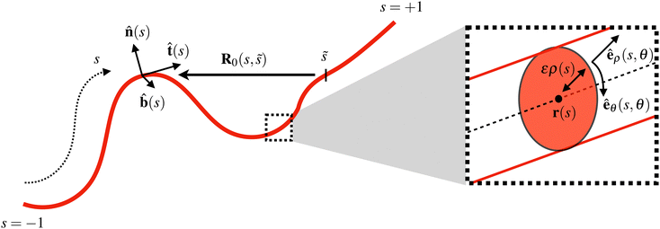 |
| | Fig. 2 Illustration of the geometry of a slender phoretic filament. The position of the filament centreline is given by the vector r(s), where s ∈ [−1,1] is the arclength. At any point s, the filament has a tangent ![[t with combining circumflex]](https://www.rsc.org/images/entities/b_char_0074_0302.gif) (s), normal (s), normal ![[n with combining circumflex]](https://www.rsc.org/images/entities/b_char_006e_0302.gif) (s) and binormal (s) and binormal ![[b with combining circumflex]](https://www.rsc.org/images/entities/b_char_0062_0302.gif) (s). The vector between points on the centreline at s and (s). The vector between points on the centreline at s and ![[s with combining tilde]](https://www.rsc.org/images/entities/i_char_0073_0303.gif) is given by R0(s, is given by R0(s,![[s with combining tilde]](https://www.rsc.org/images/entities/i_char_0073_0303.gif) ) = r(s) − r( ) = r(s) − r(![[s with combining tilde]](https://www.rsc.org/images/entities/i_char_0073_0303.gif) ). The inset shows a zoom of the cross-section, which has a radius ερ(s), where ε ≪ 1 is the slenderness. Locally, we define coordinates êρ and êθ, which point radially outward and azimuthally around the cross-section. All quantities shown are dimensionless. ). The inset shows a zoom of the cross-section, which has a radius ερ(s), where ε ≪ 1 is the slenderness. Locally, we define coordinates êρ and êθ, which point radially outward and azimuthally around the cross-section. All quantities shown are dimensionless. | |
We consider the phoretic problem outlined in eqn (1)–(3), expanding the surface concentration, c(s,θ), in powers of the slenderness, so that
| | | c(s,θ) = c(0)(s,θ) + εc(1)(s,θ) + O(ε2). | (5) |
The leading-order surface concentration for a general activity,

is
1| | 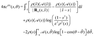 | (6) |
where

represents the
θ-integrated value of a function and
R0(
s,
![[s with combining tilde]](https://www.rsc.org/images/entities/i_char_0073_0303.gif)
) =
r(
s) −
r(
![[s with combining tilde]](https://www.rsc.org/images/entities/i_char_0073_0303.gif)
) is the vector joining two points on the centreline. For an axisymmetric activity,

the leading-order and next-order concentrations are found to be
1| |  | (7) |
| | 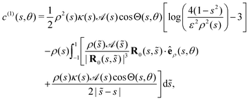 | (8) |
where
κ(
s) is the curvature of the centreline. The resulting slip velocity over the surface of the swimmer can then be determined as a surface gradient of the concentration
| |  | (9) |
Note that gradients in concentration around the azimuthal direction around a cross-section,
i.e. in the
θ direction, are magnified by a factor 1/
ε in the slip velocity.
3 Fourier decomposition for arbitrary activity
In previous work on SPT,1 results focused on examples of slender phoretic filaments that have axisymmetric activity profiles. However, this theory, unlike many other slender-body theories, can account for azimuthal variation in activity. This is very important for autophoretic particles because the effect of concentration gradients in the slender azimuthal direction is significant, since they are amplified by a factor 1/ε in the slip velocity, as shown in eqn (9). This means that, for a non-axisymmetric activity, it is often not necessary to calculate the next-order mode, c(1), to determine the leading-order expression for the slip velocity (and hence swimming) which is of size ε−1, since  . This contrasts with axisymmetric activities, where the slip velocity is generated equally by gradients in c(0) along the arclength, s, and θ gradients in c(1), which both occur at O(1). We expect that variations in the activity in the azimuthal direction around a cross-section will have a significant impact on the dynamics of the slender phoretic filament and so this case must be addressed. Here, we show a method for calculating the leading-order surface concentration for an arbitrary non-axisymmetric activity profile on a slender body with arbitrary 3D shape.
Fourier decomposition of surface properties can be used to exploit the linearity of Laplace's equation in studying complex patterning of phoretic swimmers.22 Following other similar work for slender bodies in Stokes flow,12 we decompose the (known) activity and (unknown) surface concentration into Fourier modes
| |  | (10) |
| |  | (11) |
where we recall that
Θ(
s,
θ) =
θ −
θi(
s) is the azimuthal angle around a cross-section after accounting for the torsion of the centreline, tracked by
θi(
s), and the zeroth-order Fourier mode for the activity is

where

is the activity integrated over a cross-section. Note that although we may refer to
eqn (10) as a Fourier expansion for the activity, it is really the expansion for

. The
ρ(
s) is included in this expansion because it is proportional to the surface element and so occurs in all integrals over the surface.
The leading-order surface concentration for a slender filament that does not necessarily have an axisymmetric activity is given by eqn (6). Applying this Fourier expansion to eqn (6) (details in App. A), we find the Fourier modes for the concentration in terms of the activity modes as
| |  | (12) |
| |  | (13) |
| |  | (14) |
Given the Fourier decomposition of the activity

in
eqn (10), we can therefore find the Fourier decomposition of the concentration field
c(
s,
θ) in
eqn (11). Notice that the expression for the zeroth mode,
eqn (12), is the same as for an axisymmetric profile,
eqn (7). Thus, the concentration field for any non-axisymmetric activity profile on any slender filament shape can be readily found from the axisymmetric solution with the same geometry, before adding the higher order modes from
eqn (13) and (14).
3.1 Azimuthally-varying activity for arbitrary geometry
To demonstrate this theory, we now consider calculating the leading-order surface concentration for some concrete examples of azimuthally-varying activity which have  . In this case the concentration field depends only on the local activity to leading order. For any non-zero averaged profiles with variations of this form, eqn (12)–(14) show that we can simply add on the axisymmetric result of the average profile.
3.1.1 Polar activity profile.
Consider the polar activity  for some integer n ≥ 1, which has a zero azimuthal average,
  . The activity has a single non-zero Fourier mode and so we can write the concentration as
| |  | (15) |
The corresponding leading-order slip velocity for such a swimmer is| |  | (16) |
This may appear to be independent of the geometry, since the cross-sectional radius dependence, ρ(s), in the concentration disappears due to a factor 1/ρ in the azimuthal slip in eqn (9). However, it is important to note that the fixed body-frame direction êθ is geometry-dependent, and the resulting fluid flow from considering the slip velocity over the whole surface will also depend on the shape.
3.1.2 Azimuthal antisymmetric Janus activity.
Often, in practical applications, we are interested in swimmers that are patterned such that there are discrete patches with different uniform surface properties (e.g. activity) over the surface. Of particular interest are Janus swimmers, which are half active and half inert. We give analytical solutions for particular Janus filaments in Section 5, but here focus on the solution for an arbitrary filament with a zero azimuthal average for the activity,  which is
| |  | (17) |
The Fourier expansion of this activity is| |  | (18) |
for which we calculate the leading-order surface concentration and slip velocity as| |  | (19) |
| |  | (20) |
We note that while the axisymmetric form of the SPT equations was extensively validated against Boundary Element Method simulations in Katsamba et al.,1 non-axisymmetric cases were not considered in that work. Therefore we present a brief validation for the Janus azimuthal antisymmetric activity prolate spheroid here. A Regularised Boundary Element Method based on the authors' previous work13 is employed, but with a simplified “constant panel” representation of the unknown surface concentration. The surface of a prolate spheroid with slenderness ε = 0.1 was meshed with 5952 shape-quadratic triangles by deforming a regular mesh of the containing cuboid x ∈ [−1,1] × [−0.1,0.1] × [−0.1,0.1]. The geometry, surface-patterning, numerical, and asymptotic solutions are shown in Fig. 3. The pointwise percentage relative error Eerror = 100|(casym − cnum)|/max|cnum| between the asymptotic and numerical solutions is shown in Fig. 3, demonstrating that our asymptotic solution produces a good approximation of the concentration field, even for the relatively low-aspect ratio of 1![[thin space (1/6-em)]](https://www.rsc.org/images/entities/char_2009.gif) :
:![[thin space (1/6-em)]](https://www.rsc.org/images/entities/char_2009.gif) 10 here, with a maximum relative error of max Eerror = 4%.
10 here, with a maximum relative error of max Eerror = 4%.
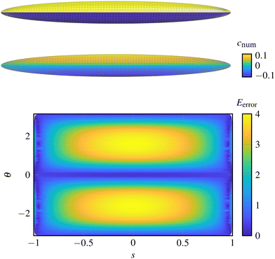 |
| | Fig. 3 Results and validation of the Janus azimuthal antisymmetric activity prolate spheroid. Top: The surface activity, with  on both halves. Middle: The concentration profile on the spheroid's surface, and Bottom: The relative percentage error in the asymptotic solution vs. the Boundary Element solution, showing good agreement. on both halves. Middle: The concentration profile on the spheroid's surface, and Bottom: The relative percentage error in the asymptotic solution vs. the Boundary Element solution, showing good agreement. | |
4 Universal solution for straight filaments
We now move to consider the simplest class of phoretic slender objects: straight filaments. The aim is to find a universal method for calculating the surface concentration profile for this common class of slender geometries. We have just seen that arbitrary activity profiles can be decomposed into an axisymmetric contribution of the θ-averaged profile and Fourier modes that encapsulate the azimuthal variation. We thus start by considering an axisymmetric solution for straight filaments, before combining this with the previous Fourier decomposition result to obtain a universal solution for slender straight filaments with arbitrary activity.
4.1 Axisymmetric activity
We consider a straight filament with an axisymmetric activity,  . Note that the cross-section ρ(s) and activity
  can still vary along the length of the filament.
Since the filament centreline is straight, the arclength, s, is simply the coordinate along an axis parallel to the swimmer, which we shall denote by y to distinguish the straight centreline results from the general curved results elsewhere. The distance between points on the centreline at s = y and s = x is then |R0| = |x − y|. Further, we note that because straight filaments have zero curvature, κ = 0, and any vector between two points on the centreline is perpendicular to the unit vector pointing radially outwards from any cross-section, R0·êρ = 0, then the first-order correction to the surface concentration is zero, c(1) = 0. Thus the expression for the surface concentration is
| |  | (21) |
We write

as a series expansion in Legendre polynomials,
| |  | (22) |
where
Pn(
y) is the Legendre polynomial of order
n. Note that these polynomials are orthogonal, so that they obey the relation

which means that the coefficients,

can be calculated
via| |  | (23) |
Importantly, the Legendre polynomials also obey
| |  | (24) |
with
L0 = 0 and

for
n > 0, so that the integral term in
eqn (21) can be simplified. We can then write the surface concentration as
| |  | (25) |
Note that for a prolate spheroidal cross-section,

the Legendre polynomials are eigenfunctions of
eqn (22) with eigenvalues −
Ln/2 + log(2/
ε).
Therefore, given an arbitrary axisymmetric activity on a slender straight rod, we can calculate the concentration field in terms of a Legendre polynomial expansion of the activity. Its derivative with respect to y gives the slip velocity in the tangential direction. This Legendre polynomial form of solution is well-known for other slender-body theories, such as in Stokes flows26 where it has been applied to simulate suspensions of flexible fibres.27 Our result could be used in a similar manner to improve simulations of slender phoretic emulsions.
4.2 Arbitrary chemical patterning
For a straight rod with an arbitrary activity on its surface, the results of Section 3 mean that any surface concentration can be calculated as a sum of a Legendre polynomial expansion of the cross-sectionally-averaged activity and a Fourier series of the azimuthal variation of the activity around the centreline. We therefore find a universal solution for straight filaments:| |  | (26) |
where the  here are the Legendre polynomial expansion coefficients for the azimuthally integrated profile
  . Note that, because the filament is straight (and has a circular cross-section), we are able to parametrise our centreline curve so that it has no torsion, and so here we have used that Θ(y,θ) = θ.
5 Directly integrable cases
Having derived some general results for arbitrary phoretic filaments and straight rods, we now turn to calculate analytical solutions for the surface solute concentration and slip velocity in a few specific examples that can be solved directly by integrating the SPT equations. These examples are illustrated in Table 1. As discussed in Section 4, we could find solutions for the examples that have straight centrelines in terms of Legendre polynomials, however, for these basic examples, we instead choose to evaluate the integrals exactly rather than in terms of a (possibly infinite) Legendre polynomial expansion.
Table 1 Illustration of the geometry and chemical patterning of the examples calculated in Section 5. The activity is denoted by colour, ranging from active ( yellow) to inert (
 blue). Note that all cross-sections are circular, and here we show a semicircular arc which has half-angle α = π/2
|
|
Activity profile |
| Uniform |
Azimuthal Janus |
Middle |
| Shape: |
Rod |

|

|

|
| Spheroid |

|

|

|
| Arc |

|

|

|
For non-prolate spheroidal filaments, such as uniform radius rods ρ(s) = const., we note that the equations of SPT are not fully valid in a small region near the ends of the filament (see appendix of SPT1), unless the activity there is zero. This is a common attribute of slender body theories, since the assumption of slenderness breaks down at the ends of the filaments.12 In such cases, it is possible to perform a matched asymptotic analysis to resolve the concentration at the ends, which can in certain circumstances have an effect on the overall swimming velocity.28 However, this analysis lies beyond the scope of this work, and in these few cases we instead consider the solution that is valid over the majority of the filament. A few helpful tips for deriving the results presented here are given in the App. B.
We shall also discuss the resulting swimming direction of each of the examples in the case of constant mobility, by considering the symmetries of the geometry and resulting slip velocities. In general, SPT is valid for arbitrary mobilities,  and the variation of this property over the surface of the phoretic filament may lead to swimming in directions that are not aligned with geometrical symmetry axes. The general calculation of this swimming motion involves incorporating a slender body theory for the fluid flow around the filament on top of the SPT for the slip velocity, and will not be calculated here.
5.1 Cylinders
The first example we consider is the simplest possible slender swimmer: a cylinder. The cylinder has a straight centreline and a constant cross-sectional radius, ρ = 1. Recall also that, because the cylinder is straight, the first-order correction to the surface concentration must be zero, c(1) = 0.
5.1.1 Uniform activity.
For a cylinder with a uniform activity,  the only contribution to the concentration is from the logarithm term in the expansion, eqn (21), which gives
| |  | (27) |
The corresponding slip velocity is found by differentiating with respect to the arclength to give| |  | (28) |
where ![[t with combining circumflex]](https://www.rsc.org/images/entities/b_char_0074_0302.gif) always points in the y-direction for a cylinder. This solution diverges at the ends, y = ±1, but we expect our solution to lose validity close to the ends where the shape of the end caps becomes important and regularises the solution. Due to the symmetry of the uniform cylinder, we expect that there will be no net motion if the mobility is uniform,
always points in the y-direction for a cylinder. This solution diverges at the ends, y = ±1, but we expect our solution to lose validity close to the ends where the shape of the end caps becomes important and regularises the solution. Due to the symmetry of the uniform cylinder, we expect that there will be no net motion if the mobility is uniform,  but the slip flow will generate a bulk straining flow with a finite stresslet in the far-field.
5.1.3 Middle activity.
For the final example of a cylinder, we again consider patches of active and inert regions, but this time the variation is in the long (i.e. s) direction. We suppose that the middle section between y = a and y = b is active, whereas the rest is inert. This is a generalisation of both the Saturn and Janus cylinders considered in previous work,1 for which a = −sc, b = sc and a = 0, b = 1, respectively. The activity in this case can be written as| |  | (32) |
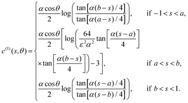
The corresponding leading-order surface concentration and slip velocity are calculated as
| | 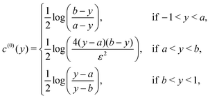 | (33) |
| |  | (34) |
Both the concentration and slip velocity solutions reduce to the uniform activity result when
a = −1 and
b = +1.
These middle activity cylinders will generally swim along their axis if the mobility is uniform over the surface. A Saturn cylinder will not swim due to its fore-aft symmetry, but will generate a bulk straining flow in the surrounding fluid.
Note that there is a divergence in the concentration field and the slip velocity close to the jumps in activity at y = a,b. We will show in Section 6 that a small region close to the jump regularises this discontinuity in the concentration, where we provide the appropriate formula for calculation in this region, and so we expect the calculated behaviour to be suitable except in a small region close to the jump in activity.
5.2 Prolate spheroids
Another basic example that we can consider is the prolate spheroid, with  . Again, this example has a straight centreline and so c(1) = 0. For these examples, the solution is valid close to the ends (see appendix of Katsamba et al.1).
5.2.2 Upper-half Janus.
We can also consider a prolate spheroid with the non-axisymmetric Janus activity defined by eqn (29). Just as for the cylinders, this activity is simply the sum of the uniform activity of Section 5.2.1 and the azimuthal antisymmetric Janus example of Section 3.1.2, all divided by 2:| |  | (37) |
| |  | (38) |
For a uniform mobility, the net swimming is perpendicular to the slender axis, along the direction θ = ±π/2 (vertically as shown in Table 1).
5.3 Circular arcs
We now consider a simple slender structure whose centreline is not straight: an arc of a circle that has half-angle α, with a uniform cross-section ρ = 1. Since these examples do not have a straight centreline, the O(ε) contribution to the concentration field is now non-zero, and must also be calculated as it impacts the slip velocity at O(1).
Note that, for these circular arcs, the curvature is κ = α (with 0 < α < π) and the vector between points on the centreline, R0, obeys
| |  | (41) |
| |  | (42) |
5.3.2 Upper-half Janus.
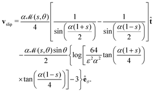
For an azimuthally varying activity, it is not necessary to calculate the first-order correction to the surface concentration, c(1), to determine the leading-order slip velocity, since the angular concentration gradients are magnified by a factor 1/ε, and so we neglect this term here. Hence, we can again write down the leading-order solution for the non-axisymmetric Janus activity defined by eqn (29) (but with s replacing y) for circular arcs as| |  | (46) |
| |  | (47) |
The upper-half Janus circular arc will also translate along its axis of reflectional symmetry if the mobility is constant, although we may expect enhanced swimming compared to the uniformly active circular arc (potentially in the opposite direction) due to the factor ε−1 in the slip velocities.
5.3.3 Middle activity.
We can also calculate the concentration field and slip velocity for a circular arc that has a central region that is active, and inert ends. The activity is again given by eqn (32), with y replaced by the arclength s, as above. Then the leading-order concentration is found to be| | 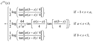 | (48) |
with the next-order contribution
The resulting slip velocity is| | 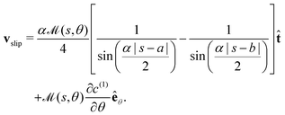 | (49) |
Again, we can see that setting a = −1 and b = +1 gives the same result as for a uniform activity in the central region, and can obtain results for Janus and Saturn circular arcs by particular choices of a and b. Note that, in the limit α → 0, this reduces to the cylindrical result of Section 5.1 (as do the previous two examples).
When the mobility is uniform, the swimming direction of this circular arc with middle activity has both a translational and rotational component in the plane of the centreline. For the specific case of a Saturn-patterned activity, there is no rotation and the arc moves along its axis of reflectional symmetry, similarly to the other circular arc examples.
As with the cylinders, we also find an apparent divergence in our results near the jumps in activity. This is a general phenomenon because the assumption of slowly varying activity, that is used when deriving SPT, breaks down. We now turn to consider this issue in more detail, by investigating whether the results can be regularised by smoothing the activity profile over a small region around the jump.
6 Discrete jumps in activity
The derivation of the SPT equations assumes that the activity,  varies slowly with respect to the inner scale ε. This condition arose because derivatives of
  with respect to s were discarded in the inner expansion of the system, but this is violated when there are sharp jumps in activity (such as several cases considered in previous work,1 as well as the middle activity filaments considered above). However, note that there is no assumption on the activity in the θ-direction, and so results for fast variations around this azimuthal direction, such as in Section 3.1.2, remain valid in this theory. Here, we investigate the influence of sharp jumps in activity along the length of the slender body on the resulting surface concentration by considering the effect of a small transition region that regularises the activity.
Consider an activity profile that has a sharp jump between  and
and  around a point s = s0. We consider an axisymmetric activity, for simplicity, but our results hold regardless of if there is θ-variation. On either side of the jump there is a region much smaller than ε in which the activity changes from a to b. We write this activity as
| |  | (50) |
where
s −
s0 ∈ [−
εn,
εn] is the transition region,
n > 1 determines the size of the region and
η(
s) is the transition function that smoothly connects the two regions. In the limit
n → ∞ this representation becomes a jump. An example
η(
s) that satisfies these conditions is
| |  | (51) |
where erf(
x) is the error function, with erf(
x) → ±1 as
x → ±∞.
The influence of this small region on the SPT equations can be identified by considering its effect on points that are either far from or close to the transition region, respectively. We focus on the effect of the jump on the leading-order contribution at each location; the size of the jump's contributions to higher-order terms must be smaller than this for the asymptotic expansion of SPT to remain valid. For full details of the derivation of the expansion, see Section 2.5 and Appendix A ans B in SPT.1
6.1 Far contributions
We start by considering the effect of the sharp jump on a point s that is far from the transition region. In this case, the jump's contribution is contained within the outer expansion of the SPT equations, since it is much further away than the slenderness, s − s0 = O(1). After asymptotically expanding in powers of ε, we find (as before) that the contribution from this jump ignores the thickness of the filament and is as if all points were on the centreline. The key integral of the leading-order contribution to this outer expansion is then| |  | (52) |
where F(s) is the far field contribution. Inserting the form of the activity chosen above, eqn (50), we find| |  | (53) |
The first and last of the above integrals are of O(1) while the second one is of O(εn) for s0 far from s. Discarding terms larger than ε we find that| | 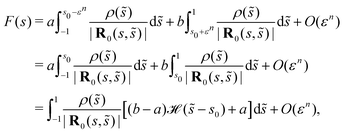 | (54) |
where  is the Heaviside step function. This shows that, far from the step, the contribution of the transition is equivalent to a jump in activity to the accuracy considered.
6.2 Near contributions
For points that are close to the jump in activity, the transition region instead affects the inner expansion of SPT, where s − ![[s with combining tilde]](https://www.rsc.org/images/entities/i_char_0073_0303.gif) = O(ε). Previous SPT expansions are valid provided that the activity varies slowly, since the approximation
= O(ε). Previous SPT expansions are valid provided that the activity varies slowly, since the approximation  was used in the inner region. This is not appropriate close to the transition region where the activity varies rapidly. We expand all other terms as before, so that the leading-order inner contribution (before integrating over
 ![[small theta, Greek, tilde]](https://www.rsc.org/images/entities/i_char_e123.gif) ) is
) is| | 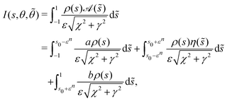 | (55) |
where we have written the denominator in terms of χ = (s − ![[s with combining tilde]](https://www.rsc.org/images/entities/i_char_0073_0303.gif) )/ε and γ2 = 2ρ2(s)[1 − cos(θ −
)/ε and γ2 = 2ρ2(s)[1 − cos(θ − ![[small theta, Greek, tilde]](https://www.rsc.org/images/entities/i_char_e123.gif) )]. Note that
)]. Note that  is the leading-order distance between two points on the surface of the filament when they are close together. The first and third integral in the last line above can be evaluated exactly and expanded in ε, just like the usual SPT derivation, but the second integral cannot be evaluated without a specific η(s). However, it is possible to create an upper bound on the size of this integral, since
| |  | (56) |
where max[⋯] selects the maximum of the arguments, and we have used that |η(s)| ≤ max[|a|,|b|] for the second inequality. This integral can then be calculated by using the substitution ![[s with combining tilde]](https://www.rsc.org/images/entities/i_char_0073_0303.gif) = s + ε γsinh
= s + ε γsinh![[thin space (1/6-em)]](https://www.rsc.org/images/entities/char_2009.gif) ϕ (i.e. χ = γsinh
ϕ (i.e. χ = γsinh![[thin space (1/6-em)]](https://www.rsc.org/images/entities/char_2009.gif) ϕ) to find
ϕ) to find| | 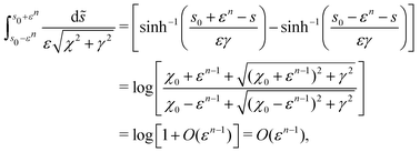 | (57) |
where we have applied the identity  before replacing s0 − s with χ0 = (s0 − s)/ε = O(1). Note that, although I is singular when γ → 0 with χ0 = 0, the singularity is logarithmic and therefore is integrable once the
 ![[small theta, Greek, tilde]](https://www.rsc.org/images/entities/i_char_e123.gif) integral is applied. Hence the integral of the inner kernel is approximately
integral is applied. Hence the integral of the inner kernel is approximately| | 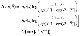 | (58) |
This reduces to the standard result for the inner expansion if a = b.
6.3 Combining the contributions
This result for the inner region can be combined with the respective outer and common regions to give the equation for the concentration in the transition region. The leading order concentration equation in the transition region is therefore| |  | (59) |
for s ∈ [s0 − εn,s0 + εn]. The error on this equation remains finite as n → ∞ and so still holds in the limit of a very sharp transition. Hence in the limit of a step-function activity this equation only applies at the location of the jump.
This analysis of the near and far contributions therefore shows that (apart from at the location of the jump itself) the presence of finite jumps in the activity has no effect on the concentration profile. At the jump points, however, the concentration changes to reflect the size of the jump.
7 Discussion
Deriving analytical solutions is a key step in improving and testing physical theories, as well as providing a shortcut for validation and speed for future numerical solvers. In this work, we have derived analytic solutions for, and extensions to, Slender Phoretic Theory,1 finding readily applicable results for determining the solute concentration and slip velocity on the surface of a slender phoretic filament, with a slenderness parameter ε ≪ 1.
In recent years, improved manufacturing techniques have generated more complex chemical patterning on experimental phoretic particles,29,30 and it is important for the corresponding phoretic theories to handle the possibility of arbitrary patterning. Therefore, for a general slender geometry, we considered the effect of activities that varied in the azimuthal direction around a cross-section. This slender variation had been previously neglected despite its significant effect on the slip velocity. The leading-order concentration was decomposed into a Fourier series expansion, with the zeroth-order mode simply being the concentration due to the axisymmetric cross-sectional average of the activity. If the filament has a straight centreline, such as for cylinders and ellipsoids, we showed that the solution for filaments with an axisymmetric activity can be written as a Legendre polynomial expansion of the activity along the arclength. The error in this solution is O(ε2). The linearity of the phoretic equations means that these two results can be combined so that any general activity on a slender filament with a straight centreline can be written as the sum of a Legendre polynomial expansion of the cross-sectional average activity and a Fourier expansion of the variation in the azimuthal direction around a cross-section.
We then calculated non-trivial analytic solutions on some basic geometries by directly integrating the SPT equations. In particular, we derived solutions for the surface solute concentration and slip velocity on cylinders, prolate spheroids and circular arcs with a uniform activity, as well as activities proportional to the cross-sectional radius and with only the top half active, and cylinders and circular arcs with activity only in a central region. Results for Janus and Saturn cylinders and arcs can be easily determined as specific cases of the middle activity results. We also discussed the qualitative swimming behaviours for each example when the mobility is uniform. However, we note that our theory works for arbitrary mobility and the resulting slip velocities can be used as input in fluid dynamics software to explore the vast possibilities of swimming kinematics that emerge when varying mobility is allowed. In practice, however, both the activity and mobility depend on the chemical properties of the surface, and being able to independently vary these along the surface might not be entirely possible.
Dividing the swimmer's surface into active and inert region is a common design for phoretic swimmers since it is easily realisable in practice; Janus particles are the canonical phoretic swimmer. These designs have sharp jumps in their activity, and we found that the resulting solution for the concentration field is discontinuous close to the jump. This coincides with a breakdown in the assumptions of SPT due to a fast-varying activity along the filament. We resolved this apparent issue by considering a smoothed activity profile in a small region around the jump. In this region, the variation of the activity occurs on a scale where the width of the filament cannot be ignored. By considering the near and far contributions to the local concentration field, we showed that the presence of the jump has a negligible effect on the solution away from the transition region as its width gets smaller and approaches a step-function activity, whereas near this region the concentration averages between the profiles on either side. This shows that the SPT solutions are valid for sharp jumps in activity, except close to the jump itself where the singular concentration is regularised.
From this basic collection of solutions, we can determine a whole library of more complex results, because the linearity of the phoretic equations (and Stokes flow) means that solutions with the same geometry can be added together in linear combinations. As such, it is a simple extension to find the concentration and slip velocity which combine the presented results, such as quarter-active cylinders, or circular arcs with stripes that have different levels of activity.
Our work expands the methods for calculating the surface solute concentration and slip velocity of a slender phoretic filament, as well as providing an assortment of analytic solutions for some basic geometries and chemical patterning. Knowledge of these analytic results is crucial for future validation of numerical techniques on slender phoretic swimmers, and may help with the development of pairwise interaction models for models of dilute suspensions of chemically active filaments. Future technologies may exploit the interaction of flexibility and phoretic propulsion to generate elaborate shape change, such as that observed in the transverse propulsion of a flexible chain,31 as well for the control of artificial microbots.11 Our examples can be used to gain early insights into how this may occur, such as understanding the slip flow on a Saturn-patterned phoretic cylinder that buckles into a circular arc and spontaneously propels. We hope that our study inspires further work into the phoretic locomotion of slender objects, expanding the library of known solutions and developing experimental realisations of such swimmers.
Author contributions
P. K. and M. B. contributed equally to this work. P. K. derived the general solutions in Sections 3 and 4. P. K. & M. B. calculated the analytical examples in Sections 4 and 5. M. B. prepared and edited the manuscript. L. K. developed the argument for sharp jumps in Section 6. M. B & T. M.-J. prepared the figures. T. M.-J. performed the numerics, secured the funding, and supervised the work. All authors have reviewed and approved the manuscript.
Conflicts of interest
The authors declare no competing interests.
Appendix
A Non-axisymmetric activity
Substituting the Fourier series for the activity, eqn (10), into the general expression for the leading-order concentration, eqn (6), we find| | 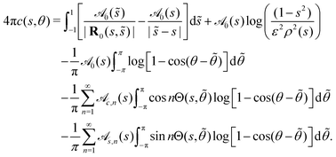 | (60) |
These integrals in ![[small theta, Greek, tilde]](https://www.rsc.org/images/entities/i_char_e123.gif) can be evaluated by using the substitution ϕ =
can be evaluated by using the substitution ϕ = ![[small theta, Greek, tilde]](https://www.rsc.org/images/entities/i_char_e123.gif) − θ and noting that12
− θ and noting that12
| |  | (61) |
| |  | (62) |
| |  | (63) |
Therefore, we find that
| |  | (64) |
Comparing this to the Fourier expansion for the concentration,
eqn (11), gives the required result.
B Useful hints for calculating analytical results
Here, we note a few tips that may help anyone that wants to reproduce our analytical results given in Section 5. Note that, in general, care has to be taken to evaluate the integral near where the denominator in the integrand (e.g. |R0|) is zero, since the integrand diverges.
B.1 Uniform prolate spheroid
A prolate spheroid is a straight filament with a cross-section  . If the activity is uniform,
  then the surface concentration is given by
| |  | (65) |
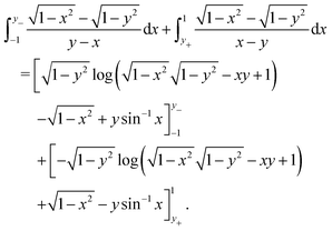
We break the integral up from x = −1 to x = y− = y − δ and from x = y+ = y + δ to x = 1:
| |  | (66) |
Evaluating this and taking the limit δ → 0 gives the required result.
B.2 Circular arcs
The integration for all of the circular arc examples is significantly simplified once you note that| |  | (67) |
Acknowledgements
P. K. was supported in part by the Engineering and Physical Sciences Research Council (EPSRC) grant EP/R041555/1 “Artificial Transforming Swimmers for Precision Microfluidics Tasks” to T. M.-J. M. B. was supported by the Leverhulme Trust Research Leadership Award “Shape-Transforming Active Microfluidics” to T. M.-J. L. K. was funded by Australian Research Council (ARC) under the Discovery Early Career Research Award scheme (grant agreement DE200100168).
References
- P. Katsamba, S. Michelin and T. D. Montenegro-Johnson, J. Fluid Mech., 2020, 898, A24 CrossRef CAS.
- W. F. Paxton, K. C. Kistler, C. C. Olmeda, A. Sen, S. K. S. Angelo, Y. Cao, T. E. Mallouk, P. E. Lammert and V. H. Crespi, J. Am. Chem. Soc., 2004, 126, 13424–13431 CrossRef CAS PubMed.
- B. J. Williams, S. V. Anand, J. Rajagopalan and M. T. A. Saif, Nat. Commun., 2014, 5, 3081 CrossRef PubMed.
- J. L. Anderson, Ann. Rev. Fluid Mech., 1989, 21, 61–99 CrossRef.
- R. Golestanian, T. B. Liverpool and A. Ajdari, Phys. Rev. Lett., 2005, 94, 220801 CrossRef PubMed.
- B. J. Nelson, I. K. Kaliakatsos and J. J. Abbott, Annu. Rev. Biomed. Eng., 2010, 12, 55–85 CrossRef CAS PubMed.
- C. Maggi, J. Simmchen, F. Saglimbeni, J. Katuri, M. Dipalo, F. De Angelis, S. Sanchez and R. Di Leonardo, Small, 2016, 12, 446–451 CrossRef CAS PubMed.
- R. Golestanian, T. B. Liverpool and A. Ajdari, New J. Phys., 2007, 9, 126 CrossRef.
- R. D. Baker, T. Montenegro-Johnson, A. D. Sediako, M. J. Thomson, A. Sen, E. Lauga and I. Aranson,
et al.
, Nat. Commun., 2019, 10, 1–10 CrossRef CAS PubMed.
- M. F. Velho Rodrigues, M. Lisicki and E. Lauga, PLoS One, 2021, 16, e0252291 CrossRef CAS PubMed.
- T. D. Montenegro-Johnson, Phys. Rev. Fluids, 2018, 3, 062201 CrossRef.
- L. Koens and E. Lauga, J. Fluid Mech., 2018, 850, R1 CrossRef.
- T. D. Montenegro-Johnson, S. Michelin and E. Lauga, Eur. Phys. J. E: Soft Matter Biol. Phys., 2015, 38, 1–7 CrossRef CAS PubMed.
- E. Yariv, J. Fluid Mech., 2008, 613, 85–94 CrossRef.
- O. Schnitzer and E. Yariv, Phys. Fluids, 2015, 27, 031701 CrossRef.
- E. Yariv, Langmuir, 2019, 36, 6903–6915 CrossRef PubMed.
- A. Varma, T. D. Montenegro-Johnson and S. Michelin, Soft Matter, 2018, 14, 7155–7173 RSC.
- A. Walther and A. H. Müller, Soft Matter, 2008, 4, 663–668 RSC.
- S. Michelin and E. Lauga, J. Fluid Mech., 2014, 747, 572–604 CrossRef.
- S. Ebbens, D. A. Gregory, G. Dunderdale, J. R. Howse, Y. Ibrahim, T. B. Liverpool and R. Golestanian, Eur. Phys. Lett., 2014, 106, 58003 CrossRef.
- A. Brown and W. Poon, Soft Matter, 2014, 10, 4016–4027 RSC.
- M. Lisicki, S. Y. Reigh and E. Lauga, Soft Matter, 2018, 14, 3304–3314 RSC.
- W. Uspal, M. N. Popescu, S. Dietrich and M. Tasinkevych, Soft Matter, 2015, 11, 434–438 RSC.
- S. Michelin, T. D. Montenegro-Johnson, G. De Canio, N. Lobato-Dauzier and E. Lauga, Soft Matter, 2015, 11, 5804–5811 RSC.
- L. C. Schmieding, E. Lauga and T. D. Montenegro-Johnson, Phys. Rev. Fluids, 2017, 2, 034201 CrossRef.
-
T. Götz, PhD thesis, University of Kaiserslautern, Kaiserslautern, Germany, 2000.
- A.-K. Tornberg and M. J. Shelley, J. Comput. Phys., 2004, 196, 8–40 CrossRef.
- Y. Ibrahim, R. Golestanian and T. B. Liverpool, Phys. Rev. Fluids, 2018, 3, 033101 CrossRef.
- H. R. Vutukuri, Z. Preisler, T. H. Besseling, A. Van Blaaderen, M. Dijkstra and W. T. Huck, Soft Matter, 2016, 12, 9657–9665 RSC.
- R. Archer, A. Campbell and S. Ebbens, Soft Matter, 2015, 11, 6872–6880 RSC.
- K. Prathyusha, F. Ziebert and R. Golestanian, Soft Matter, 2022, 18, 2928–2935 RSC.
Footnote |
| † These authors contributed equally to this work. |
|
| This journal is © The Royal Society of Chemistry 2022 |
Click here to see how this site uses Cookies. View our privacy policy here.  Open Access Article
 ab,
Matthew D.
Butler†
 b,
Lyndon
Koens
 cd and
Thomas D.
Montenegro-Johnson
 *b
*b


 is the activity on the surface, which is the rate at which the solute is released there (or depleted when
  ); and
  is the mobility, which relates the surface concentration gradients to the slip velocity. Both the activity and mobility are given properties of the surface, and may vary over the swimmer's surface; swimmers with the same geometry and different patterning of activity and/or mobility will behave differently. For example, a wide range of different swimming behaviours can be produced by varying the placement of patches of activity and mobility on spheres.22

![[thin space (1/6-em)]](https://www.rsc.org/images/entities/char_2009.gif) Θ(s,θ)
Θ(s,θ)![[n with combining circumflex]](https://www.rsc.org/images/entities/b_char_006e_0302.gif) (s) + sin
(s) + sin![[thin space (1/6-em)]](https://www.rsc.org/images/entities/char_2009.gif) Θ(s,θ)
Θ(s,θ)![[b with combining circumflex]](https://www.rsc.org/images/entities/b_char_0062_0302.gif) (s) with Θ(s,θ) = θ − θi(s), where
(s) with Θ(s,θ) = θ − θi(s), where ![[n with combining circumflex]](https://www.rsc.org/images/entities/b_char_006e_0302.gif) (s),
(s), ![[b with combining circumflex]](https://www.rsc.org/images/entities/b_char_0062_0302.gif) (s) are the normal and binormal vectors of the centreline and θi(s) follows the torsion of the centreline, ∂θi/∂s = τ(s). Note that we are assuming that the cross-section is always circular. The inverse aspect ratio, termed the slenderness parameter ε = rf/l is the ratio of the maximum cross-sectional radius, rf, to the half-length of the swimmer's centreline, l. For slender swimmers, the slenderness parameter is small, ε ≪ 1.
(s) are the normal and binormal vectors of the centreline and θi(s) follows the torsion of the centreline, ∂θi/∂s = τ(s). Note that we are assuming that the cross-section is always circular. The inverse aspect ratio, termed the slenderness parameter ε = rf/l is the ratio of the maximum cross-sectional radius, rf, to the half-length of the swimmer's centreline, l. For slender swimmers, the slenderness parameter is small, ε ≪ 1.
 is1
is1
 represents the θ-integrated value of a function and R0(s,
![[s with combining tilde]](https://www.rsc.org/images/entities/i_char_0073_0303.gif) ) = r(s) − r(
) = r(s) − r(![[s with combining tilde]](https://www.rsc.org/images/entities/i_char_0073_0303.gif) ) is the vector joining two points on the centreline. For an axisymmetric activity,
) is the vector joining two points on the centreline. For an axisymmetric activity,  the leading-order and next-order concentrations are found to be1


 . This contrasts with axisymmetric activities, where the slip velocity is generated equally by gradients in c(0) along the arclength, s, and θ gradients in c(1), which both occur at O(1). We expect that variations in the activity in the azimuthal direction around a cross-section will have a significant impact on the dynamics of the slender phoretic filament and so this case must be addressed. Here, we show a method for calculating the leading-order surface concentration for an arbitrary non-axisymmetric activity profile on a slender body with arbitrary 3D shape.


 where
where  is the activity integrated over a cross-section. Note that although we may refer to eqn (10) as a Fourier expansion for the activity, it is really the expansion for
  . The ρ(s) is included in this expansion because it is proportional to the surface element and so occurs in all integrals over the surface.


 in eqn (10), we can therefore find the Fourier decomposition of the concentration field c(s,θ) in eqn (11). Notice that the expression for the zeroth mode, eqn (12), is the same as for an axisymmetric profile, eqn (7). Thus, the concentration field for any non-axisymmetric activity profile on any slender filament shape can be readily found from the axisymmetric solution with the same geometry, before adding the higher order modes from eqn (13) and (14).
 . In this case the concentration field depends only on the local activity to leading order. For any non-zero averaged profiles with variations of this form, eqn (12)–(14) show that we can simply add on the axisymmetric result of the average profile.
 for some integer n ≥ 1, which has a zero azimuthal average,
  . The activity has a single non-zero Fourier mode and so we can write the concentration as

 which is


![[thin space (1/6-em)]](https://www.rsc.org/images/entities/char_2009.gif) :
:![[thin space (1/6-em)]](https://www.rsc.org/images/entities/char_2009.gif) 10 here, with a maximum relative error of max Eerror = 4%.
10 here, with a maximum relative error of max Eerror = 4%. . Note that the cross-section ρ(s) and activity
  can still vary along the length of the filament.

 as a series expansion in Legendre polynomials,
 which means that the coefficients,
  can be calculated via

 for n > 0, so that the integral term in eqn (21) can be simplified. We can then write the surface concentration as
 the Legendre polynomials are eigenfunctions of eqn (22) with eigenvalues −Ln/2 + log(2/ε).

 here are the Legendre polynomial expansion coefficients for the azimuthally integrated profile
  . Note that, because the filament is straight (and has a circular cross-section), we are able to parametrise our centreline curve so that it has no torsion, and so here we have used that Θ(y,θ) = θ.
 yellow) to inert (
 blue). Note that all cross-sections are circular, and here we show a semicircular arc which has half-angle α = π/2
 and the variation of this property over the surface of the phoretic filament may lead to swimming in directions that are not aligned with geometrical symmetry axes. The general calculation of this swimming motion involves incorporating a slender body theory for the fluid flow around the filament on top of the SPT for the slip velocity, and will not be calculated here.
 the only contribution to the concentration is from the logarithm term in the expansion, eqn (21), which gives

![[t with combining circumflex]](https://www.rsc.org/images/entities/b_char_0074_0302.gif) always points in the y-direction for a cylinder. This solution diverges at the ends, y = ±1, but we expect our solution to lose validity close to the ends where the shape of the end caps becomes important and regularises the solution. Due to the symmetry of the uniform cylinder, we expect that there will be no net motion if the mobility is uniform,
always points in the y-direction for a cylinder. This solution diverges at the ends, y = ±1, but we expect our solution to lose validity close to the ends where the shape of the end caps becomes important and regularises the solution. Due to the symmetry of the uniform cylinder, we expect that there will be no net motion if the mobility is uniform,  but the slip flow will generate a bulk straining flow with a finite stresslet in the far-field.


 . Again, this example has a straight centreline and so c(1) = 0. For these examples, the solution is valid close to the ends (see appendix of Katsamba et al.1).
 has a leading-order surface concentration


 (i.e. the activity is proportional to the cross-sectional radius of the slender prolate spheroid) has concentration

![[t with combining circumflex]](https://www.rsc.org/images/entities/b_char_0074_0302.gif) is always in the y-direction because prolate spheroids are straight rods.
is always in the y-direction because prolate spheroids are straight rods.


 the leading-order surface concentration is calculated to be



 varies slowly with respect to the inner scale ε. This condition arose because derivatives of
  with respect to s were discarded in the inner expansion of the system, but this is violated when there are sharp jumps in activity (such as several cases considered in previous work,1 as well as the middle activity filaments considered above). However, note that there is no assumption on the activity in the θ-direction, and so results for fast variations around this azimuthal direction, such as in Section 3.1.2, remain valid in this theory. Here, we investigate the influence of sharp jumps in activity along the length of the slender body on the resulting surface concentration by considering the effect of a small transition region that regularises the activity.
 and
and  around a point s = s0. We consider an axisymmetric activity, for simplicity, but our results hold regardless of if there is θ-variation. On either side of the jump there is a region much smaller than ε in which the activity changes from a to b. We write this activity as


 is the Heaviside step function. This shows that, far from the step, the contribution of the transition is equivalent to a jump in activity to the accuracy considered.
![[s with combining tilde]](https://www.rsc.org/images/entities/i_char_0073_0303.gif) = O(ε). Previous SPT expansions are valid provided that the activity varies slowly, since the approximation
= O(ε). Previous SPT expansions are valid provided that the activity varies slowly, since the approximation  was used in the inner region. This is not appropriate close to the transition region where the activity varies rapidly. We expand all other terms as before, so that the leading-order inner contribution (before integrating over
 ![[small theta, Greek, tilde]](https://www.rsc.org/images/entities/i_char_e123.gif) ) is
) is
![[s with combining tilde]](https://www.rsc.org/images/entities/i_char_0073_0303.gif) )/ε and γ2 = 2ρ2(s)[1 − cos(θ −
)/ε and γ2 = 2ρ2(s)[1 − cos(θ − ![[small theta, Greek, tilde]](https://www.rsc.org/images/entities/i_char_e123.gif) )]. Note that
)]. Note that  is the leading-order distance between two points on the surface of the filament when they are close together. The first and third integral in the last line above can be evaluated exactly and expanded in ε, just like the usual SPT derivation, but the second integral cannot be evaluated without a specific η(s). However, it is possible to create an upper bound on the size of this integral, since
![[s with combining tilde]](https://www.rsc.org/images/entities/i_char_0073_0303.gif) = s + ε γsinh
= s + ε γsinh![[thin space (1/6-em)]](https://www.rsc.org/images/entities/char_2009.gif) ϕ (i.e. χ = γsinh
ϕ (i.e. χ = γsinh![[thin space (1/6-em)]](https://www.rsc.org/images/entities/char_2009.gif) ϕ) to find
ϕ) to find
 before replacing s0 − s with χ0 = (s0 − s)/ε = O(1). Note that, although I is singular when γ → 0 with χ0 = 0, the singularity is logarithmic and therefore is integrable once the
 ![[small theta, Greek, tilde]](https://www.rsc.org/images/entities/i_char_e123.gif) integral is applied. Hence the integral of the inner kernel is approximately
integral is applied. Hence the integral of the inner kernel is approximately


![[small theta, Greek, tilde]](https://www.rsc.org/images/entities/i_char_e123.gif) can be evaluated by using the substitution ϕ =
can be evaluated by using the substitution ϕ = ![[small theta, Greek, tilde]](https://www.rsc.org/images/entities/i_char_e123.gif) − θ and noting that12
− θ and noting that12


 . If the activity is uniform,
  then the surface concentration is given by


