
 Open Access Article
 This Open Access Article is licensed under a Creative Commons Attribution-Non Commercial 3.0 Unported Licence
Producing shape-engineered alginate particles using viscoplastic fluids†
Sima
Asadi
 a,
Arif Z.
Nelson‡
b and
Patrick S.
Doyle
*abc
a,
Arif Z.
Nelson‡
b and
Patrick S.
Doyle
*abc
aDepartment of Chemical Engineering, Massachusetts Institute of Technology, Cambridge, MA 02139, USA. E-mail: pdoyle@mit.edu
bCritical Analytics for Manufacturing Personalized-Medicine, Singapore-MIT Alliance for Research and Technology, Singapore 138602, Singapore
cHarvard Medical School Initiative for RNA Medicine, Boston, MA 02215, USA
First published on 31st August 2022
Abstract
Non-spherical hydrogel particles are of fundamental interest and can find use in a variety of applications ranging from pharmaceuticals to biomedical to food. Here, we report a new method that leverages the yield stress property of viscoplastic fluids to synthesize shape-engineered alginate particles. By dripping an aqueous viscoplastic solution composed of sodium alginate and a yield-stress material into an ionic gelation bath, droplets are controllably deformed and crosslinked, producing a wide assortment of shapes. We find that by tuning the yield stress of the solution and the nozzle tip orientation, a range of shapes from symmetric and near-spherical, to asymmetric and anisotropic (e.g., egg-, rice grain-, arc-, ring-, snail shell-, tear-, and tadpole-like) can be produced. We explain our observations using scaling analysis of the forces exerted on the droplet at different stages of particle production. We show that the main factors that determine the degree of droplet deformation during bath entry and the final appearance of the alginate particles are the initial shape of the droplets, the timescales of the viscoplastic fluid relaxation versus the crosslinking reaction, and the physico-chemical properties of the yield-stress material.
1 Introduction
Hydrogel particles are hydrated 3D networks of crosslinked polymer chains that have found diverse application in the biomedical, pharmaceutical, environmental, food, and cosmetic industries due to their versatile nature with highly tunable physical and chemical properties.1–5 Hydrogel particles are extensively used for controlled drug delivery,6–8 cell and islet encapsulation,9–12 scaffold building and 3D biofabrication,13,14 biosensing,15 bioactive delivery in aquaculture,16 and water treatment.17 Hydrogels can be made of both natural and synthetic polymers.1 Alginate is a natural anionic polysaccharide derived from brown algae that can be crosslinked in the presence of divalent cations such as Ca2+ to form stable hydrogels.18 Due to its biocompatibility, biodegradability, non-toxicity, low-cost, tunable mechanical properties, and swelling behavior, alginate is an ideal candidate for a wide range of biomedical and pharmaceutical applications.18,19Prior research on producing alginate hydrogel particles has mostly focused on producing spherical shapes. Extrusion is a well-known method used to produce large (>1 mm) spherical alginate particles at a low production rate by simply dripping an alginate solution from a nozzle into a gelation bath.20–22 This technique can be modified to produce smaller particles at a higher production rate using electrostatic potential,23,24 a vibrating nozzle,25 jet-cutting,26 and centrifugal force.27,28 Emulsification methods such as mechanical stirring and high-speed homogenization that involve dispersing an alginate solution in an immiscible liquid followed by a gelation process are also used to produce a broad range of particles from 10 to 1000 μm.21,29 Over the past two decades, there has been a growing interest in microfluidics to produce spherical alginate particles because it allows for precise control over size, production rate, and properties of the particles.30–33
Non-spherical hydrogel particles have received tremendous attention in the past decade because of several advantageous features they offer compared to the more common spherical particles. These features include higher surface area-to-volume ratios, shorter diffusion distances for encapsulated loads,10,34 anisotropic responses to external stimuli,35,36 better attachment to cells and tissues,37,38 enhanced targeting as drug carriers, and controllable drug circulation and release dynamics inside the body.39,40 Given these advantages, numerous methods have been developed to produce non-spherical hydrogel particles from different polymer systems (see Cai et al.,41 Zhu et al.,42 Dendukuri et al.,30 Champion et al.,37 and the references therein). Less attention, however, has been devoted to produce non-spherical alginate particles and the diversity of the shapes generated with current techniques is limited.
Extrusion dripping combined with microfluidics or electrospraying has been used to produce non-spherical alginate particles (e.g., mushroom-like, hemispherical, red blood cell-like, and tadpole-like shapes) by altering parameters such as the distance between nozzle tip and gelation bath surface, fluid (extruded fluid or bath) viscosity, and surface tension.36,40,43–45 Anisotropic gelation of an alginate solution extruded from a bevel-tip capillary was also used to produce hydrogel microsprings.46 Recently, ‘vortex ring freezing’ method has been developed and used to produce toroidal alginate and chitosan particles. In this technique, the droplets from an electrospray nozzle enter a miscible fluid bath during which they deform and experience various intermediate shapes. These intermediate shapes can be frozen into particles in order to make teardrop, jelly fish, and toroidal shapes.34,47
In this work, we report a new method to produce non-spherical alginate particles by making use of viscoplastic fluids. Viscoplastic fluids (also known as yield-stress fluids) are a class of complex materials that behave like an elastic solid below a threshold applied stress (i.e. a ‘yield stress’), and flow like a fluid above the yield stress.48–50 Viscoplastic materials are abundant among everyday cosmetic and food products (e.g., toothpaste and ketchup). Due to their extremely useful flow behaviour, there is a growing interest in these materials for various applications including drug delivery51 and 3D printing of continuous structures.52,53 Recently, a new technique has been developed for ‘embedded droplet printing’ in which individual droplets are generated and fixed in place inside a yield-stress fluid bath that can subsequently be manipulated and used for biological assays and as microreactors.54,55 Dripping behavior of viscoplastic fluids has also been extensively investigated. It has been shown that the drops of viscoplastic fluids formed at the nozzle tip, transition from spherical to prolate shapes by increasing the yield stress value.56–59 Here, we leverage the ability of viscoplastic fluids in forming non-spherical droplets and combine it with the gel-forming capacity of sodium alginate to tune the shape of alginate particles. We use the extrusion dripping technique to drip non-spherical viscoplastic droplets composed of sodium alginate and a yield-stress material into a CaCl2 gelation bath. We use two yield-stress materials with distinct microstructures for which the yield stress comes about by either jammed, repulsive or networked, attractive, interactions. We show that after vertical bath entry of the prolate viscoplastic droplets, they undergo further deformation and a crosslinking reaction, producing a range of shapes from near-spherical to egg-, rice grain-, and tear-like. In addition, we find that tuning the nozzle orientation alters the shape of viscoplastic droplets significantly and intensifies the degree of droplet deformation during bath entry, yielding an assortment of spectacular asymmetric, anisotropic, shapes. We further demonstrate that changing the type of yield-stress material can affect the shape, size, and appearance of the alginate particles. We find that within our investigated range, increasing the concentration of the gelation bath did not have a significant effect on the shape and size of the particles.
2 Materials and methods
2.1 Preparing solutions
2.2 Rheological characterization
Rheological measurements were performed using a TA Instruments DHR-3 combined motor/transducer rotational rheometer with a flat-plate upper geometry (diameter = 40 mm) and bottom Peltier plate at 25![[thin space (1/6-em)]](https://www.rsc.org/images/entities/char_2009.gif) °C; results are shown in Fig. 1(a) and (b). Sand paper (Norton, grit = 180) was used to avoid slip at low shear rates. Shear-rate controlled experiments were performed in the shear rate range of 10−2 <
°C; results are shown in Fig. 1(a) and (b). Sand paper (Norton, grit = 180) was used to avoid slip at low shear rates. Shear-rate controlled experiments were performed in the shear rate range of 10−2 < ![[small gamma, Greek, dot above]](https://www.rsc.org/images/entities/i_char_e0a2.gif) < 102 and 10−2 < < 1 for C-σy and X-σy solutions, respectively. Note that xanthan gum formulations are generally thixotropic and we only observed a clear yield-stress signature for X-σy solutions when ramping the shear rate from low to high. Carbomer solutions, on the other hand, are non-thixotropic and for our C-σy solutions, the yield stress measurements were independent of the ramp direction. For consistency, we present low-to-high shear rate ramp data for both formulations, and therefore probe the static yield stress. The data sets were fit to the Herschel–Bulkley model to obtain the shear yield stress of the samples (σ = σy + kn, where σ, σy, k, and n are shear stress, yield stress, consistency index, and flow index, respectively).
< 102 and 10−2 < < 1 for C-σy and X-σy solutions, respectively. Note that xanthan gum formulations are generally thixotropic and we only observed a clear yield-stress signature for X-σy solutions when ramping the shear rate from low to high. Carbomer solutions, on the other hand, are non-thixotropic and for our C-σy solutions, the yield stress measurements were independent of the ramp direction. For consistency, we present low-to-high shear rate ramp data for both formulations, and therefore probe the static yield stress. The data sets were fit to the Herschel–Bulkley model to obtain the shear yield stress of the samples (σ = σy + kn, where σ, σy, k, and n are shear stress, yield stress, consistency index, and flow index, respectively).
 | ||
| Fig. 1 Shear-rate controlled test results for (a) C-σy and (b) X-σy solutions. The solid curves correspond to Herschel Bulkley (H–B) model fits used to calculate the yield stress of the solutions, σy. (c) Experimental setup to study viscoplastic droplet formation at the nozzle tip, its entry to a CaCl2 bath, and its deformation and ionic crosslinking to form alginate particles. | ||
2.3 Experiments
Fig. 1(c) shows a schematic of the experimental setup used to produce shape-engineered alginate particles. Viscoplastic solutions (C-σy and X-σy) were dripped from a 14G nozzle (Nordson EFD, inner diameter D0 = 1.54mm, length = 12.7mm) into a CaCl2 gelation bath using a syringe pump (Harvard Apparatus, PHD 2000 series, Infuse/Withdraw) operating at Q0 = 0.05ml min−1. For selecting a value for Q0, we ensured that a small variation in the flow rate does not alter the shape of extruded filaments and droplets. The nozzle was positioned at an angle θ with respect to the horizontal direction (i.e., θ = 90° for a vertical nozzle). The distance between the nozzle tip and bath surface was h ≈ 4 cm and the droplet impact velocity, U0, was measured using image processing just before the droplet impacts the bath surface. Previous work measuring the surface tension of Carbopol and xanthan gum solutions found only small deviations from that of water, and therefore, here we use the surface tension of water (i.e., γ = 0.072N m−1 at 20 °C) for our calculations.60,61 A Phantom Miro M 320S Vision Research high-speed camera connected to a Nikon AF-S DX Nikkor 18–70 mm lens recorded the process at a resolution of 1024 × 1024pixels. Droplet formation and pinch-off at the nozzle tip were recorded at 200 fps, while the droplet free fall in the air and bath entry were recorded at 2000 fps. After the bath entry, droplets were allowed to stay in the gelation bath until the crosslinking reaction was complete and the food dye diffused out completely. The resultant alginate particles were then removed from the bath and washed with DI water several times. We then allowed the particles to stay in DI water for 48 h before taking their images to ensure that they were in an equilibrium swollen state. Finally, images of the particles were captured with an LCD digital microscope (PalliPartners, ASIN B08LVM9361) while they were inside the DI water. Different approaches may be used to calculate the size of droplets and particles using either their volume or projected area (Fig. S1, ESI†). Considering the asymmetric shape of the droplets and particles in our experiments, calculating an accurate volume is a challenging task. Therefore, for consistency in our analysis, we chose to use 2D images of the droplets and particles to calculate their projected area diameter, i.e., DA = (4A/π)1/2.
3 Results and discussion
3.1 Effect of σy
Fig. 2 shows the stages of producing alginate particles from C-σy solutions dripped from a 14G nozzle angled at θ = 90° into a 2 wt% CaCl2 gelation bath. During the droplet formation stage, a competition between surface tension and yield-stress forces, described with the dimensionless number β = σyDA/γ, determines the initial shape of the droplets.57 At low σy (β ∼ O(0.1)), surface tension force deforms the fluid filament that is extruded from the nozzle to a pear-like shape (Fig. 2(a), column 1). As σy increases (β ∼ O(1–10)), the filament is less deformed and it takes a more prolate shape (Fig. 2(b)–(e), column 1). In all cases, the filament continues growing until the normal stress due to the fluid weight (∼ρfgL), exceeds its elongational yield-stress, σy,e .62 At a critical filament length of lc ∼ σy,e/(ρfg) the fluid yields locally below the nozzle tip and necking starts. At this stage, neck diameter, Dn, continues decreasing as the normal stress increases with ∼1/D2n,56,59 and eventually the droplet pinches off (Fig. 2(b)–(e), column 2). After the onset of necking until the droplet pinches off, its length, L, does not change significantly and can be approximated by lc (Fig. 3). Upon pinch-off the rear end of droplet and the residual fluid tip attached to the nozzle slightly retract. During the free fall (Fig. 2(b)–(e), column 3), all droplets maintain their shape since the drag force in the air (∼ρaCDU20D2A) is not strong enough to overcome the yield stress (∼σyD2A) and deform the droplets.63
 | ||
| Fig. 2 Effect of σy on the shape of alginate particles. Particles are formed by dripping (a) C-4.19, (b) C-18.2, (c) C-42.5, (d) C-74.0, and (e) C-102 solutions from a 14G vertical nozzle (θ = 90°) into a 2 wt% CaCl2 bath. The columns show different stages of the particle production, final shape of the particles, and histograms of the projected area diameter, DA, for the particles. The red scale bar is 5 mm for all images and the corresponding videos are provided in Movie S1 (ESI†). | ||
 | ||
| Fig. 3 Droplet length, L, versus critical length, lc = σy,e/(ρfg), for C-σy and X-σy solutions. Each data point is the average of 3 trials and the error bars (not shown) are smaller than the marker size. Dotted lines are used as a guide for the eyes. | ||
When C-4.19 and C-18.2 droplets impact the bath surface with U0 = 0.81 ± 0.01m s−1, the bottom of the droplets flattens and they take oblate and pear-like shapes, respectively (Fig. 2(a) and (b), columns 4 and 5). Previous work on water entry of viscoplastic Carbopol droplets showed more deformation at this range of σy and U0 than observed here.63 The smaller deformation observed in our experiments can be attributed to the presence of sodium alginate in our viscoplastic solutions and the ionic crosslinking reaction that begins upon droplet entry to the gelation bath. For C-42.5, C-74.0, and C-102 solutions, the droplet tip deformation upon impact (U0 = 0.69 ± 0.05m s−1) is less pronounced due to higher σy (Fig. 2(c)–(e), column 4). The small difference observed between the impact velocities of the droplets despite having similar release heights (h ≈ 4 cm), is due to the difference in the length of the droplets. Upon impact, the droplet is perturbed and an overturning couple is formed that makes the droplet tip move in the lateral direction and rotate as it penetrates into the bath.64 While the lower part of the droplet decelerates due to impact and higher drag force exerted by the bath (∼ρbCDU20D2A), its upper part falls almost freely, leading to a vertical velocity mismatch. Therefore, the droplet buckles elastoplastically during the bath entry (Fig. 2(c)–(e), column 5).
After the rear end of the deformed viscoplastic droplet detaches from the bath surface, it relaxes partially during sinking (Fig. 2(a)–(e), column 6). At this stage, a competition between the time scales of the viscoplastic fluid relaxation and the crosslinking reaction plays an important role in determining the final shape of the particles. Although, the time required for full crosslinking might be higher than the relaxation time scale,65–67 a partial crosslinking that starts from the edges of droplet might be strong enough to limit the degree of relaxation and freeze the shape of particle. The final shape of the particles are depicted in the last column of Fig. 2(a)–(e) along with the histograms of their projected area diameter. A range of shaped particles from near-spherical to egg-like and rice grain-like were produced. The small coefficient of variation (CV = SD/μ) of the particle size distributions indicate that the particles were uniform in size. The images of Fig. 2 show that the sizes of particles are smaller than the sizes of uncrosslinked droplets, even in their fully swollen (un-dried) state. It is unlikely that this shrinkage is due to diffusion of the Carbomer macromolecules out of the particles into the bath considering the diffusion time scale of Carbomer (O(103–104)s),68 and the fact that the particles shrink considerably during the first few minutes of bath entry. In addition, comparing the alginate mesh size (≈ 10–100nm depending on the polymer solution and gelation bath concentration69) and the size of unswollen Carbomer macromolecules (average diameter ≈ 20–410nm depending on the molecular weight70) suggests that Carbomer diffusion is unlikely to happen. Instead, the decrease in the size of particles can be attributed to shrinkage of alginate after gelation.20 Furthermore, it is known that Carbomer microgels deswell and precipitate in the presence of di- and multi-valent ions.54,71,72 Therefore, Ca2+ ion diffusion from the gelation bath into the particles can contribute to their shrinkage by deswelling the Carbomer.
3.2 Effect of θ
Fig. 4 demonstrates the stages of alginate particle production using C-74.0 and C-102 solutions dripped from a 14G nozzle angled at θ = 60°, θ = 30°, or θ = 0° into a 2 wt% CaCl2 bath. As mentioned earlier for the case of θ = 90°, the residual fluid attached to the nozzle tip retracts and becomes unyielded quickly after a droplet pinches off. For a tilted nozzle, when fresh fluid is extruded out, the filament initially follows a trajectory in the direction of nozzle tip. However, it quickly yields locally, bends downward, and rotates underneath the nozzle above a critical length of due to the action of a gravitational moment which overcomes the yield stress.73 Note that the filament tip remains unyielded. After the filament collapses toward the vertical direction, it continues growing until its weight exceeds σy,e and the droplet pinches off. After pinch-off, and during the free fall, the droplet buckles plastically with a degree inversely proportional to θ, due to its asymmetric geometry. For C-74.0 solution dripping at θ = 0°, the droplet formation stage differs slightly from other configurations (Fig. 4(c), column 1); as soon as the fluid is extruded out from the nozzle and starts rotating underneath the extrusion point, the tip of the fluid adheres to the outer wall of the nozzle. The filament first coils up like a snail shell, and then as the fluid weight increases, it detaches from the nozzle wall and pinches off.
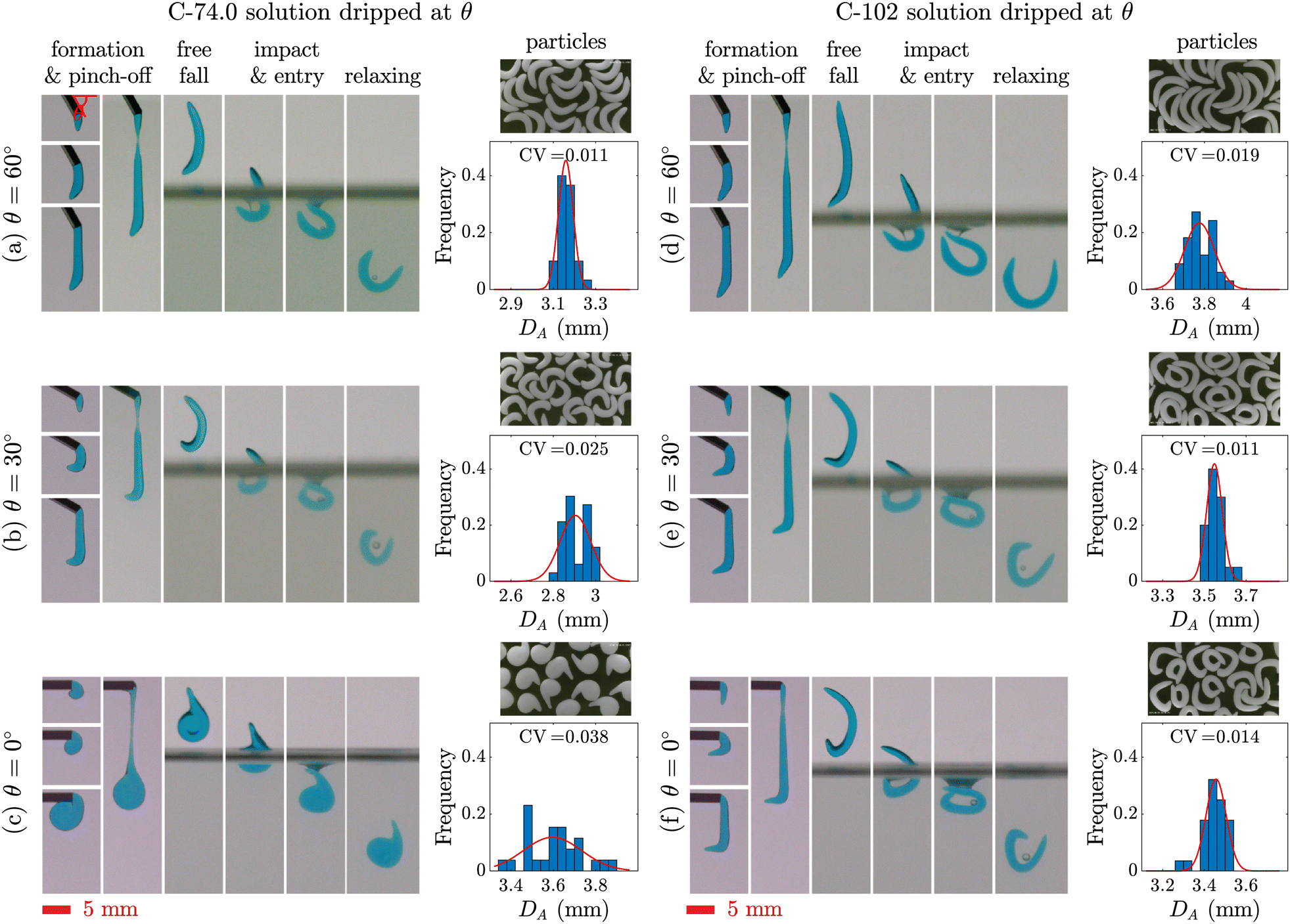 | ||
| Fig. 4 Effect of θ on the shape of alginate particles. Particles are formed by dripping C-74.0 (left) and C-102 (right) solutions from a 14G nozzle angled at (a), (d) θ = 60°, (b), (e) θ = 30°, or (c), (f) θ = 0°. The columns show different stages of the particle production, final shape of the particles, and histograms of the projected area diameter, DA, for the particles. The red scale bars are 5 mm for all images and the corresponding videos are provided in Movie S2 (ESI†). | ||
The fundamental mechanism for the droplet impact and entry to the gelation bath for the tilted nozzles is similar to the case of θ = 90°. However, here the droplets have already buckled during the formation and free fall, and therefore are prone to further deformation. When a buckled droplet hits the bath surface, its lower half enters the bath and an air cavity is initially formed. The lower half of the droplet remains attached to the cavity, decelerates significantly, and deforms plastically. The upper half falls with a higher vertical velocity and bends dramatically over the lower half as it falls. When the lower half of the droplet is detached from the cavity, an air bubble sticks to its wall which subsequently detaches from the droplet or bursts. In some configurations (Fig. 4(b), (e), and (f)), the two ends of the droplet come together and form a ring shape. After the droplet pinches off from the bath surface completely, the upper half of the droplet relaxes back slightly and the droplet continues sinking in the bath and fully solidifies. The final shape of the particles and the corresponding size histograms are depicted in the last column of Fig. 4. Snail shell-like and arc-shaped particles were produced by changing θ. Occasionally, for the conditions shown in Fig. 4(e) and (f), the droplet tail sticks to its head during deformation and maintains its shape, forming a ring-shaped particle.
3.3 Effect of changing yield-stress material
To investigate the behavior of an attractive network-based yield-stress fluid and produce a wider range of shaped alginate particles, we replaced Carbomer with a different rheological modifier, xanthan gum. Xanthan gum is a natural polysaccharide produced by Xanthomonas campestris bacterium that can be used to prepare shear-thinning58 and yield-stress fluids.74Fig. 5(a) shows the stages of non-spherical alginate particle production using X-σy viscoplastic solutions. The formation stage of the X-σy droplets (column 1) is very similar to C-σy droplets; as σy increases, the shape of the droplets becomes more prolate. However, neck length, defined as twice the distance between nozzle tip and minimum neck diameter position, increases significantly before the droplet pinches off (Fig. 5(a), column 2). After pinch-off, X-σy droplets are longer than C-σy droplets with similar σy (Fig. 3). The high extensibility behavior of the X-σy solutions can be attributed to the long-chain, stretchy, attractive polymer network of xanthan gum compared to the repulsive-dominated systems with small extensibility such as Carbomer.75 During the free fall, there is no significant change in the shape of droplets, except the retraction of the neck filament residue upon pinch-off. The X-5.45 droplets flatten upon impact and entry into the 2 wt% CaCl2 bath, producing an oblate shape that subsequently relaxes back partially and generates a particle with an egg-like shape. X-12.3, X-16.4, and X-22.6 droplets buckle as they enter the bath, similar to the C-σy droplets. After the droplets completely enter the bath and detach from the bath surface, they partially relax back towards their initial shape and continue sinking until the crosslinking reaction is complete. The final shape of X-σy particles at their equilibrium swollen state are shown in the last column of Fig. 5(a). | ||
| Fig. 5 Using xanthan gum to impart a yield stress. Different stages of particle formation from (a) X-σy solutions dripped from a 14G nozzle positioned at θ = 90° and (b) X-22.6 solution dripped from a nozzle angled at θ = 60°, θ = 30°, or θ = 0° into a 2 wt% CaCl2 bath. The red scale bars are 5 mm for all images and the corresponding videos are provided in Movies S3 and S4 (ESI†). The image contrast of the X-σy particles has been enhanced to increase the visibility of the transparent particles. | ||
The effect of nozzle orientation on the shape of alginate particles made from X-22.6 solution is demonstrated in Fig. 5(b). Droplets with a rounded tip and a large tail (tadpole-shape) are generated for θ = 60° and are further buckled after bath entry. By decreasing the angle to θ = 30°, the droplet tip becomes larger and the tail length decreases. At θ = 0°, the X-22.6 solution's behavior is similar to the C-74.0 solution. The droplet tip attaches to the nozzle wall and the droplet coils up at the nozzle tip. As the fluid is extruded, the weight of the droplet increases and it detaches from the nozzle wall to finally pinch off. The impact, entry, relaxation, and gelation stages are similar to producing particles from C-74.0 and C-102 solutions using a tilted nozzle tip. The final shape of particles are depicted in the last column of Fig. 5(b). It can be seen from Fig. 5 that the sizes of X-σy particles are considerably larger than the initial droplets. This suggests that, unlike C-σy particles, X-σy particles swell in the bath during crosslinking and their water uptake continue increasing after transferring them into DI water. In addition, X-σy particles are larger and more transparent compared to the opaque C-σy particles (Fig. 6) and their transparency increases over time in DI water. Note that the image contrast of X-σy particles has been enhanced in Fig. 5 and 6 to increase the visibility of the transparent particles. As mentioned earlier, the shrinkage behavior of C-σy particles is due to alginate crosslinking and Carbomer microgel deswelling and precipitating in the presence of Ca2+ ions. Carbomer precipitation also gives rise to the white nontransparent appearance of the C-σy particles. However, X-σy particles become more transparent as their water uptake increases.
 | ||
| Fig. 6 Images of all particles produced by dripping C-σy or X-σy solutions from a 14G nozzle positioned at θ = 90°, θ = 60°, θ = 30°, or θ = 0° into a 2 wt% CaCl2 bath. The red scale bar is 5 mm for all images. The image contrast has been enhanced for X-σy particles to increase their visibility. | ||
Fig. 7 depicts the analysis of the size and shape of the viscoplastic droplets and crosslinked particles in their equilibrium swollen state. We use two parameters for our analysis: projected area diameter, DA, and the Feret ratio, ψ, defined as the ratio of minimum to maximum Feret diameter. Fig. 7(a)–(d) shows that DA increases with σy for both droplets and particles. However, the Feret aspect ratio, ψ, decreases from ≈ 1 for the semi-spherical C-4.19 particles to ≈ 0.2 for C-102 particles. Thus, as σy increases, the droplets and particles become larger and more prolate. Fig. 7(e) and (h) show that DA does not change significantly with θ for the droplets and particles (except that the snail-shell shapes produced at θ = 0° from C-74.0 and X-22.6 solutions have a larger DA). In addition, ψ, which in this case is a measure of degree of buckling, decreases with θ for both droplets and particles, with the highest value for the ring-shaped particles. An interesting observation in this figure is the size of swollen particles compared to the uncrosslinked droplets which we discussed qualitatively in the previous sections. C-σy particles shrink in size after the crosslinking reaction is complete, while X-σy particles swell. We found that the degree of shrinkage and swelling increases with σy for C-σy and X-σy particles, respectively (see Fig. S2, ESI†).
 | ||
| Fig. 7 Projected area diameter, DA, and Feret ratio, ψ, versus (a), (b) σy for droplets, (c), (d) σy for particles, (e), (f) θ for droplets, and (g), (h) θ for particles. Each data point is the average of 3 trials and the error bars (not shown) are smaller than the marker size. Dotted lines are used as a guide for the eyes. | ||
Our experiments did not show a substantial change in shape and size of the alginate particles by increasing the CaCl2 bath concentration from 2 to 10 and 20 wt% (Fig. S3, ESI†), consistent with previous work on the effect of CaCl2 concentration on the morphology of tail-shaped alginate particles.40
4 Conclusions
We report a new method that leverages the flow features of viscoplastic fluids to produce shape-engineered alginate particles. A viscoplastic solution composed of sodium alginate and a yield-stress material (either Carbomer or xanthan gum) is dripped into a CaCl2 gelatin bath, where the droplet is subsequently deformed and crosslinked. We find that the morphology of viscoplastic droplets and alginate particles is significantly affected by the yield stress of the solutions, σy, nozzle tip orientation with respect to the horizontal direction, θ, and type of the yield-stress material. We explain our observations in terms of (i) a scaling analysis of the forces exerted on the droplet at different stages of particle production, (ii) a competition between the time scales of the viscoplastic fluid relaxation and the crosslinking reaction in the gelation bath, and (iii) the physico-chemical properties of the yield-stress material. We demonstrate that this method can produce uniform mm-sized alginate particles with a variety of shapes resembling spheres, eggs, rice grains, arcs, rings, snail shells, tears, and tadpoles. Our technique will find application in pharmaceutical, food, and cosmetic industries that can benefit from non-spherical particles. Future studies will focus on: (i) producing a wider range of morphologies, (ii) exploring how other parameters, such as impact velocity, alter the shape of particles, and (iii) optimizing our technique to produce non-spherical micron-sized alginate particles.Conflicts of interest
There are no conflicts to declare.Acknowledgements
We acknowledge support from the Robert T. Haslam (1911) Chair to PSD. Financial support for AZN was provided by the Pharmaceutical Innovation Programme Singapore (grant number A19B3a0012). We also thank Professor Gareth McKinley's lab at MIT for providing the high-speed camera used in our experiments.Notes and references
- K. Y. Lee and D. J. Mooney, Chem. Rev., 2001, 101, 1869–1880 CrossRef CAS PubMed.
- A. C. Daly, L. Riley, T. Segura and J. A. Burdick, Nat. Rev. Mater., 2020, 5, 20–43 CrossRef CAS PubMed.
- L. Van Gheluwe, I. Chourpa, C. Gaigne and E. Munnier, Polymers, 2021, 13, 1285 CrossRef CAS PubMed.
- D. Li, Z. Wei and C. Xue, Compr. Rev. Food Sci. Food Saf., 2021, 20, 5345–5369 CrossRef CAS PubMed.
- R. Song, S. Cho, S. Shin, H. Kim and J. Lee, Nanoscale Adv., 2021, 3, 3395–3416 RSC.
- J. Li and D. J. Mooney, Nat. Rev. Mater., 2016, 1, 16071 CrossRef CAS PubMed.
- T. G. Barclay, C. M. Day, N. Petrovsky and S. Garg, Carbohydr. Polym., 2019, 221, 94–112 CrossRef CAS.
- L.-H. Chen, L.-C. Cheng and P. S. Doyle, Adv. Sci., 2020, 7, 2001677 CrossRef PubMed.
- W.-H. Tan and S. Takeuchi, Adv. Mater., 2007, 19, 2696–2701 CrossRef CAS.
- S. Ungphaiboon, D. Attia, G. Gomez d’Ayala, P. Sansongsak, F. Cellesi and N. Tirelli, Soft Matter, 2010, 6, 4070–4083 RSC.
- Y.-C. Lu, W. Song, D. An, B. J. Kim, R. Schwartz, M. Wu and M. Ma, J. Mater. Chem. B, 2015, 3, 353–360 RSC.
- A. U. Ernst, L.-H. Wang and M. Ma, Adv. Healthcare Mater., 2019, 8, 1900423 CrossRef.
- F. Yanagawa, S. Sugiura and T. Kanamori, Regener. Ther., 2016, 3, 45–57 CrossRef.
- H. Zhang, Y. Cong, A. R. Osi, Y. Zhou, F. Huang, R. P. Zaccaria, J. Chen, R. Wang and J. Fu, Adv. Funct. Mater., 2020, 30, 1910573 CrossRef CAS.
- G. C. Le Goff, R. L. Srinivas, W. A. Hill and P. S. Doyle, Eur. Polym. J., 2015, 72, 386–412 CrossRef CAS.
- S. Masoomi Dezfooli, N. Gutierrez-Maddox, A. Alfaro and A. Seyfoddin, Rev. Aquac., 2019, 11, 631–660 CrossRef.
- D. Gokhale, I. Chen and P. S. Doyle, ACS Appl. Polym. Mater., 2022, 4, 746–754 CrossRef CAS.
- A. D. Augst, H. J. Kong and D. J. Mooney, Macromol. Biosci., 2006, 6, 623–633 CrossRef CAS PubMed.
- K. Y. Lee and D. J. Mooney, Prog. Polym. Sci., 2012, 37, 106–126 CrossRef CAS PubMed.
- B.-B. Lee, P. Ravindra and E.-S. Chan, Chem. Eng. Technol., 2013, 36, 1627–1642 CAS.
- J.-Y. Leong, W.-H. Lam, K.-W. Ho, W.-P. Voo, M. F.-X. Lee, H.-P. Lim, S.-L. Lim, B.-T. Tey, D. Poncelet and E.-S. Chan, Particuology, 2016, 24, 44–60 CrossRef CAS.
- S. H. Ching, N. Bansal and B. Bhandari, Crit. Rev. Food Sci. Nutr., 2017, 57, 1133–1152 CrossRef CAS PubMed.
- T. I. Klokk and J. E. Melvik, J. Microencapsulation, 2002, 19, 415–424 CrossRef CAS PubMed.
- K.-S. Huang, C.-H. Yang, Y.-S. Lin, C.-Y. Wang, K. Lu, Y.-F. Chang and Y.-L. Wang, Electrostatic droplets assisted synthesis of alginate microcapsules, Drug Delivery Transl. Res., 2011, 1, 289–298 CrossRef CAS PubMed.
- Y. Zhou, S. Kajiyama, H. Masuhara, Y. Hosokawa, T. Kaji and K. Fukui, J. Biomed. Sci. Eng., 2009, 2, 287–293 CAS.
- B. B. Paulo, F. d M. Ramos and A. S. Prata, J. Food Process Eng., 2017, 40, e12591 CrossRef.
- H. B. Eral, E. R. Safai, B. Keshavarz, J. J. Kim, J. Lee and P. S. Doyle, Langmuir, 2016, 32, 7198–7209 CrossRef CAS PubMed.
- K. Maeda, H. Onoe, M. Takinoue and S. Takeuchi, Adv. Mater., 2012, 24, 1340–1346 CrossRef CAS PubMed.
- D. Poncelet, V. Babak, C. Dulieu and A. Picot, Colloids Surf., A, 1999, 155, 171–176 CrossRef CAS.
- D. Dendukuri and P. S. Doyle, Adv. Mater., 2009, 21, 4071–4086 CrossRef CAS.
- H. Zhang, E. Tumarkin, R. Peerani, Z. Nie, R. M. A. Sullan, G. C. Walker and E. Kumacheva, J. Am. Chem. Soc., 2006, 128, 12205–12210 CrossRef CAS PubMed.
- L. Mazutis, R. Vasiliauskas and D. A. Weitz, Macromol. Biosci., 2015, 15, 1641–1646 CrossRef CAS PubMed.
- Y. Liu, N. Tottori and T. Nisisako, Sens. Actuators, B, 2019, 283, 802–809 CrossRef CAS.
- D. An, A. Warning, K. G. Yancey, C.-T. Chang, V. R. Kern, A. K. Datta, P. H. Steen, D. Luo and M. Ma, Nat. Commun., 2016, 7, 12401 CrossRef CAS PubMed.
- D. K. Hwang, D. Dendukuri and P. S. Doyle, Lab Chip, 2008, 8, 1640–1647 RSC.
- Y. Hu, Q. Wang, J. Wang, J. Zhu, H. Wang and Y. Yang, Biomicrofluidics, 2012, 6, 026502 CrossRef PubMed.
- J. A. Champion, Y. K. Katare and S. Mitragotri, J. Controlled Release, 2007, 121, 3–9 CrossRef CAS PubMed.
- N. Abbasi, M. Navi, J. K. Nunes and S. S. H. Tsai, Soft Matter, 2019, 15, 3301–3306 RSC.
- Y. Geng, P. Dalhaimer, S. Cai, R. Tsai, M. Tewari, T. Minko and D. E. Discher, Nat. Nanotechnol., 2007, 2, 249–255 CrossRef CAS PubMed.
- Y.-S. Lin, C.-H. Yang, Y.-Y. Hsu and C.-L. Hsieh, Electrophoresis, 2013, 34, 425–431 CrossRef CAS.
- L. Cai, F. Bian, H. Chen, J. Guo, Y. Wang and Y. Zhao, Chem, 2021, 7, 93–136 CAS.
- X. Zhu, C. Vo, M. Taylor and B. R. Smith, Mater. Horiz., 2019, 6, 1094–1121 RSC.
- Y. Hu, G. Azadi and A. M. Ardekani, Carbohydr. Polym., 2015, 120, 38–45 CrossRef CAS PubMed.
- T. Dang and S. Joo, Colloids Surf., B, 2013, 102, 766–771 CrossRef CAS PubMed.
- M. Jeyhani, S. Y. Mak, S. Sammut, H. C. Shum, D. K. Hwang and S. S. H. Tsai, ChemPhysChem, 2018, 19, 2113–2118 CrossRef CAS.
- K. Yoshida and H. Onoe, Sci. Rep., 2017, 7, 45987 CrossRef CAS PubMed.
- L. Z. Guan, M. C. Gutiérrez, L. Yuste, F. Rojo, M. L. Ferrer and F. del Monte, Carbon, 2019, 147, 408–418 CrossRef CAS.
- N. J. Balmforth, I. A. Frigaard and G. Ovarlez, Annu. Rev. Fluid Mech., 2014, 46, 121–146 CrossRef.
- A. Z. Nelson and R. H. Ewoldt, Soft Matter, 2017, 13, 7578–7594 RSC.
- D. Bonn, M. M. Denn, L. Berthier, T. Divoux and S. Manneville, Rev. Mod. Phys., 2017, 89, 035005 CrossRef.
- C. H. Lee, V. Moturi and Y. Lee, J. Controlled Release, 2009, 136, 88–98 CrossRef CAS PubMed.
- A. K. Grosskopf, R. L. Truby, H. Kim, A. Perazzo, J. A. Lewis and H. A. Stone, ACS Appl. Mater. Interfaces, 2018, 10, 23353–23361 CrossRef CAS PubMed.
- B. M. Rauzan, A. Z. Nelson, S. E. Lehman, R. H. Ewoldt and R. G. Nuzzo, Adv. Funct. Mater., 2018, 28, 1707032 CrossRef.
- A. Z. Nelson, B. Kundukad, W. K. Wong, S. A. Khan and P. S. Doyle, Proc. Natl. Acad. Sci. U. S. A., 2020, 117, 5671–5679 CrossRef CAS PubMed.
- A. Z. Nelson, J. Xie, S. A. Khan and P. S. Doyle, Adv. Mater. Technol., 2021, 6, 2001245 CrossRef CAS.
- P. Coussot and F. Gaulard, Phys. Rev. E: Stat., Nonlinear, Soft Matter Phys., 2005, 72, 031409 CrossRef CAS PubMed.
- G. German and V. Bertola, J. Non-Newtonian Fluid Mech., 2010, 165, 825–828 CrossRef CAS.
- G. German and V. Bertola, Phys. Fluids, 2010, 22, 033101 CrossRef.
- A. Geffrault, H. Bessaies-Bey, N. Roussel and P. Coussot, J. Rheol., 2021, 65, 887–901 CrossRef CAS.
- J. Boujlel and P. Coussot, Soft Matter, 2013, 9, 5898–5908 RSC.
- C.-E. Brunchi, M. Bercea, S. Morariu and M. Dascalu, J. Polym. Res., 2016, 23, 123 CrossRef.
- P. Coussot, Rheol. Acta, 2018, 57, 1–14 CrossRef CAS.
- M. Jalaal, D. Kemper and D. Lohse, J. Fluid Mech., 2019, 864, 596–613 CrossRef CAS.
- W. Xia, C. Wang, Y. Wei, J. Li, Y. Li and L. Yang, Exp. Fluids, 2020, 61, 57 CrossRef.
- J.-S. Hong and J. J. Cooper-White, Korea Aust. Rheol. J., 2009, 21, 269–280 Search PubMed.
- H. Kim, Korean J. Chem. Eng., 1990, 7, 1–6 CrossRef CAS.
- T. Braschler, A. Valero, L. Colella, K. Pataky, J. Brugger and P. Renaud, Anal. Chem., 2011, 83, 2234–2242 CrossRef CAS PubMed.
- A. L. Huang, S. V. Desai and R. M. Wellek, J. Chem. Eng. Data, 1969, 14, 356–359 CrossRef CAS.
- K. T. Campbell, K. Wysoczynski, D. J. Hadley and E. A. Silva, ACS Biomater. Sci. Eng., 2020, 6, 308–319 CrossRef CAS PubMed.
- Z. Jaworski, T. Spychaj, A. Story and G. Story, Rev. Chem. Eng., 2021, 000010151520200016 CrossRef.
- A. Nowbahar, A. O’Connor, V. Mansard, P. Spicer and T. M. Squires, Phys. Rev. Fluids, 2019, 4, 061301 CrossRef.
- T. L. Corporation, Dispersion Techniques for Carbopol Polymers, Technical Data Sheet TDS-103, The Lubrizol Corporation, Wickliffe, OH, USA, 2007 Search PubMed.
- N. J. Balmforth and I. J. Hewitt, J. Non-Newtonian Fluid Mech., 2013, 193, 28–42 CrossRef CAS.
- K.-W. Song, Y.-S. Kim and G.-S. Chang, Fibers Polym., 2006, 7, 129–138 CrossRef.
- A. Z. Nelson, R. E. Bras, J. Liu and R. H. Ewoldt, J. Rheol., 2018, 62, 357–369 CrossRef CAS.
Footnotes |
| † Electronic supplementary information (ESI) available. See DOI: https://doi.org/10.1039/d2sm00621a |
| ‡ Present address: Food, Chemical and Biotechnology Cluster, Singapore Institute of Technology, Singapore 138683, Singapore. |
| This journal is © The Royal Society of Chemistry 2022 |