
 Open Access Article
 This Open Access Article is licensed under a
 Creative Commons Attribution 3.0 Unported Licence
Cavity enhanced lab-on-fiber optrode for ultra-sensitive pH monitoring†
Federica
Gambino
a,
Paola
Cicatiello
a,
Martino
Giaquinto
 a,
Alberto
Micco
a,
Anna
Aliberti
a,
Angela Maria
Cusano
b,
Armando
Ricciardi
*a and
Andrea
Cusano
*a
a,
Alberto
Micco
a,
Anna
Aliberti
a,
Angela Maria
Cusano
b,
Armando
Ricciardi
*a and
Andrea
Cusano
*a
aOptoelectronics Group, Engineering Department, University of Sannio, Benevento, I-82100, Italy. E-mail: aricciardi@unisannio.it; a.cusano@unisannio.it
bRegional Center on Information Communication Technology (CeRICT) scrl, Benevento, I-82100, Italy
First published on 18th March 2022
Abstract
Current technologies for pH monitoring still require the use of large and rigid tools that are not suitable for studying biological processes such as cell culture and tissue metabolism analysis. In this work, we report on a miniaturized cavity enhanced optrode based on lab-on-fiber technology for pH monitoring in liquid solutions. The device consists of a resonant cavity directly integrated on top of a single mode optical fiber, where the active medium is made of a responsive material (microgel) suitably synthesized to respond to pH variations. The pH variations in the liquid solution in which the probe is immersed modulate the optical cavity length, inducing a wavelength shift of the interference fringes in the reflection spectra. Remarkable sensitivities of up to 315 nm per pH unit are experimentally observed in the pH range from 4.6 to 5.8. Moreover, sensitivities >20 nm per pH unit are found in a wide pH range from 2.9 to 8. To the best of our knowledge, these represent the highest values reported so far with optical fiber based pH sensors. Our findings set the stage for the development of compact, flexible, and highly sensitive pH sensors, opening unexplored scenarios also for in vivo pH monitoring.
Introduction
pH monitoring is important in many application fields, ranging from bio-chemical process analysis (involving bacteria, enzymes, DNA, cells, etc.) to environmental monitoring (agriculture and aquaculture), to quality control in pharmaceutical and food industries.1–5 In the specific case of clinical diagnostics, pH plays a fundamental role in cancer screening applications, allowing for discrimination between healthy and “insane” cells/tissues, the latter being characterized by a more acidic environment.6–8pH monitoring is also used for accurate cancer therapy treatments, allowing for the discrimination of cancer cells to be selectively destroyed by exploiting advanced localized approaches based on drug delivery systems.9 Moreover, the assessment of the pH levels (<5.5) of body fluids, such as sweat,10 tears,11 urine,12 and saliva,13 could provide a wealth of information about the physiological status of an individual. Nowadays, glass pH electrodes are the most widely used tools for pH monitoring, thanks to their reliability and precision. However, they are rather large (>1 mm), rigid, fragile, and sensitive to electrical field changes of the external environment. These aspects limit their use in biomedical applications such as detection in cell cultures and tissue metabolism analysis (wound healing application)1,14 which require advanced pH analysis at the micrometric scale.15 There is an increasing interest of the scientific community in developing miniaturized, easy to use, and biocompatible probes for pH monitoring. In this context, both silica and polymer optical fiber sensors have gained strong interest due to their small cross section areas, biocompatibility, immunity to electromagnetic interferences, small size, and advanced sensing performances with respect to their commercial counterparts.16–18 They also have the advantages of being lightweight and highly flexible, thus making them good candidates as wearable sensing devices.19 More importantly, optical fiber sensors are also potentially suitable for in vivo point-of-care analysis, thanks to their easy integration with catheters and needles.
In the specific case of pH monitoring, the optical fiber sensors proposed so far can be divided into two main categories. The first one includes configurations in which a functional material (typically made of a dye-doped pH-responsive gel) is integrated onto the tip of a bare fiber. This functional material is able to chemically react with the solution, producing a pH dependent fluorescent signal directly collected by the optical fiber.8,20 These devices offer good performances in terms of sensitivities and precision values (between 0.01 and 0.1 pH units) but only in narrow ranges around pH 7.8,20
The second category relies on optical fibers suitably modified by (i) introducing a periodic modulation of the fiber core refractive index (fiber Bragg gratings and long period gratings),16 (ii) removing a portion of the fiber cladding (D-shaped fibers),21 (iii) realizing thin metallic layers to excite plasmonic resonances22 or (iv) integrating optical cavities in such a way as to give rise to resonant spectral features.23 The successive integration of a pH-responsive layer modulates the resonant wavelength.16,21,23 The results reported so far demonstrate the difficulty of obtaining good performances in terms of both precision and sensitivity in a wide pH range. For example, the maximum sensitivity values (69 nm per pH unit) have been demonstrated only in a very narrow pH range of 1 unit (pH ranges 4–5 and 7–8).21
In this framework, here we propose a smart lab-on-fiber (LOF) device,24,25 where pH sensitive microgel (MG) particles are interposed between two gold layers, forming an optical cavity directly integrated onto the tip of an optical fiber.26 The swelling/collapsing of MG particles induced by the pH modification of the solution modulates the optical cavity and thus the interferometric fringes in the reflection spectrum. A remarkable sensitivity value of 315 nm per pH unit is found in the range between pH 5 and pH 6, which is very interesting for body fluid monitoring.10–13,20 In addition, values higher than 20 nm per pH unit have been experimentally observed in a wide pH range between 2.9 and 8 with precision of the order of 0.1 pH units, generally outperforming previously reported optical fiber-based pH sensors.
Results and discussion
The optical fiber probe
The developed sensor is schematically represented in Fig. 1a. It consists in a smart optical cavity directly integrated onto the fiber tip. We used a standard single mode fiber (SMF-28) that supports single-mode light propagation in the 1310/1550 nm operating wavelength. The active medium is made of pH responsive MGs sandwiched between two (12 nm thick) gold layers. MGs are crosslinked water-soluble hydrogel particles able to undergo volume-phase transition in response to environmental changes such as pH variations in this case. Therefore, the resulting optical cavity changes its size accordingly with the MG swelling dynamics, giving rise to Fabry–Perot interferometric dips in the reflection spectrum that shift in response to pH variations.23,27,28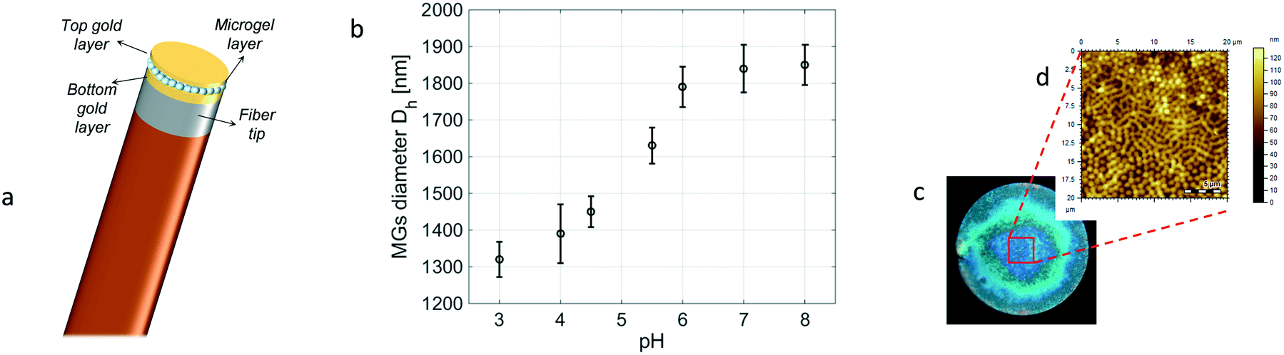 | ||
| Fig. 1 (a) Schematic representation of the cavity-probe. (b) DLS measurements showing the MGs' hydrodynamic diameter as a function of pH at 25 °C. (c) Optical microscopy image of the fiber tip after the deposition of MGs. (d) AFM characterization of the MG film in a 20 × 20 μm2 area. | ||
In order to undergo size change in response to pH variations, MGs were suitably functionalized with acrylic acid (AAc). Specifically, the MGs used were composed of 85% N-isopropylacrylamide (NIPAm), 10% AAc, and 5% N,N′-methylenebisacrylamide (BIS) as crosslinkers. pNIPAm-co-AAc MGs were synthesized via temperature-ramp, surfactant-free, free-radical precipitation polymerization by following an approach described in ref. 26. The synthesized MGs were characterized by means of dynamic light scattering (DLS) measurements to evaluate their hydrodynamic diameter as a function of pH. As shown in Fig. 1b, the MGs' diameter goes from 1320 nm (at pH = 3) to 1850 nm (at pH = 8), corresponding to an overall variation of 40.1%. The details of the DLS measurements are reported in the ESI† (section S1).
The probe was fabricated by following three main steps; first, we deposited a 12 nm thick gold layer on the cleaved facet of a standard single mode fiber by means of e-beam evaporation. Successively, the MG film was deposited onto the metallized tip by exploiting a customized dip coating procedure described in ref. 29. The MGs' distribution onto the fiber tip was controlled by suitably setting different parameters during the dipping procedure, such as temperature (T = 10 °C), pH (pH = 3), and the particle concentration (10 μg mL−1) of the solution in which the MGs were dissolved. Indeed, to realize an effective MG cavity, it is crucial to achieve good film compactness and uniformity correspondingly with the active area (i.e., that above the fiber core). In fact, a low density film may cause direct contact between the top and bottom gold layers thus preventing the MG cavity swelling. Moreover, surface roughness would be detrimental for the instauration of the optical interferometric effect.
Besides the compactness of the film, it is important to achieve a suitable thickness of the MG layer that allows it to give rise to interference effects in the selected wavelength range, with a free spectral range (FSR) smaller than or at least equal to the measurable wavelength range, in such a way as to correctly evaluate the spectral shift of the resonant fringes.26 In our case, we decided to work in the near infrared range in such a way as to use standard single-mode fibers typically used for telecom applications. For this reason, the dipping procedure was repeated twice (see section S2 in the ESI† for more details).
Fig. 1c shows the top view image of the fiber tip after the MG deposition, while in Fig. 1d we report the atomic force microscopy (AFM) morphological analysis of the realized MG film. A more detailed morphological analysis is reported in the ESI† (section S2). The MG layer is pretty uniform in the active region corresponding to the fiber core area (diameter of 8 μm), ensuring proper functioning of our device. Finally, an additional gold layer (12 nm thick) was deposited onto the MG film, in such a way as to form the optical cavity. A thin titanium film (2 nm) was used in order to improve the gold adhesion.30,31 It is worth noting that, differently from our previous work,26 the realization of the top gold layer was made possible by placing the fiber in a vertical position in the evaporation chamber. Consequently, the gold was deposited only on the top of the MG layer, leaving ‘open’ the lateral side of the cavity, in such a way as to not inhibit the cavity swelling. Moreover, differently from our previous work,26 we decided to simplify the fabrication procedure by eliminating the last critical step which is the opening of the circular ring on the top gold membrane. This allowed us to increase the fabrication yield and decrease the complexity, the time, and the cost of the entire realization procedure.
pH measurements
The sensor was immersed in a pH 2.9 aqueous solution acidified with 0.1 M HCl whose temperature was kept fixed at 25 °C by using a temperature-controlled Eppendorf tube holder.32 The pH was gradually increased up to 8 by adding 0.1 M NaOH. The pH values corresponding to the different NaOH additions were measured by means of a pH glass electrode sensor. The probe reflection spectra were continuously measured in the optrode configuration by exploiting the optical setup described in our previous work.32 The results are shown in the pseudo-color plot in Fig. 2a. The same data are also shown in Fig. 2b, where the reflection spectra pertaining to integer pH values are plotted.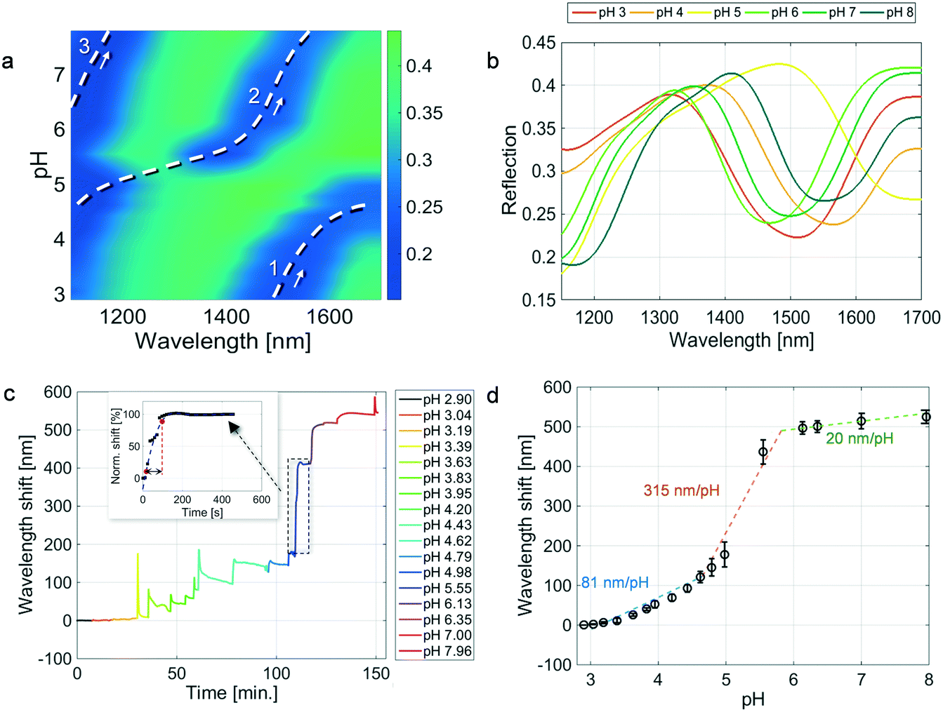 | ||
| Fig. 2 (a) Pseudocolor plot showing the reflection spectrum evolution as a function of the solution pH. The three coordinates in (a) are the wavelength (on the x axis), the pH value (on the y axis), and the reflectivity value (on the z axis) whose values are shown in the color bar. (b) Reflection spectra for different pH values. (c) Sensorgram, i.e. interference dip wavelength shift as a function of time for different pH values. (d) Steady-state values reached at each pH tested, evaluated as the mean of 3 repeated measurements (the error bar represents the standard deviation). The dashed curves in (d) represent the linear fittings in three different pH ranges. | ||
In the pseudo-color plot in Fig. 2a, we can distinguish three spectral dips (blue regions) that undergo a red-shift in response to a pH increase. The red shift is due to the cavity length increase caused by the coulombic repulsion and osmotic swelling of the MGs (see Fig. 1b). It is worth noting that there are no refractive index variations among the solutions corresponding to different pH values. Moreover, in this specific case, the MGs' refractive index variation induced by the MG swelling is estimated to be less than 1%.33
Specifically, at pH = 2.9, the reflection spectrum shows a dip localized around 1500 nm (cfr. the orange curve in Fig. 2b), which shifts toward longer wavelengths in response to a pH increase and reaches the right-end (1700 nm) of the observation wavelength window correspondingly at pH ∼4.8 (see the dashed white curve marked with the number 1 in Fig. 2a). As dip1 goes out from the wavelength window, another dip (marked with the number 2 in Fig. 2a) arises from the left side of the pseudo-color plot (cfr. the yellow spectrum in Fig. 2b) and spans the whole observed range, as traced by the dashed curve 2.
Analogously, following the spectral evolution as a function of the pH increase, a third dip is visible in the reflection spectra starting from a pH value of around 6 (see the green spectrum in Fig. 2b). Since the distance between the observed dips, namely the FSR, is lower than the observed wavelength range, it is possible to trace the whole spectral evolution, by cumulating the wavelength shifts of dip1 and dip2.26
Although interferometric dips may periodically occur at the same wavelength for different pH values, the overall spectrum contains other features (such as the dip full width at half maximum and the FSR) that can be taken into account for pH differentiation purposes.
By monitoring the dip wavelengths as a function of time for each pH solution, we obtained the sensorgram shown in Fig. 2c, which reveals a whole wavelength shift of 545 nm. The sharp peaks in the sensorgram are not due to the dynamic response of the device, but they are related to the methodology used for changing the solution pH since the additions were manually performed by using a pipettor.
Fig. 2d shows the dose–response curve, i.e., the wavelength shifts of the spectral dip as a function of the pH. Interestingly, the trend shown in Fig. 2d clearly resembles that represented in Fig. 1, also from a quantitative point of view. For each pH, the wavelength shift (shown as black dots) is the average of three values obtained during different experiments, and the error bars are the relative standard deviations. Each wavelength shift is evaluated, on its turn, as the average over an observation time of 2 minutes (10 values) after that the signal derivative over time assumes values below 0.001 nm min−1. Additionally, during our experiments we have also verified that, once the steady-state is reached, the signal remains stable for at least 1 hour.
Three linear ranges are found to have sensitivity values of 81 nm per pH unit in the low pH range up to pH 4.6 (blue line), 315 nm per pH unit in the mid pH range from pH 4.6 to pH 5.8 (orange line), and 20 nm per pH unit in the high range from pH 5.8 to pH 8 (green line).
The different sensitivity ranges are intrinsically due to the characteristics of the MG particles.
In fact, the MGs' response to pH strongly depends on their acid co-monomers' structure and composition.34 As was previously mentioned, in our case the pNIPAm-based MGs are generated by introducing AAc monomers that exhibit a pKa value of 4.3–4.8 (i.e., the negative logarithm of the acid dissociation constant (Ka) value). When the pH is above the pKa, the MG particles swell due to acid ionization of the corresponding co-monomers (AAc); conversely, the MGs collapse at pH values below the pKa due to subsequent acid neutralization.35 Consequently, according to the MGs' pH responsiveness (shown in Fig. 1b) and in line with the AAc titration curve, we observe that the wavelength minima of the reflection spectrum: i) shifted gradually below pH 4.6 (pH at which the carboxylic groups are in the protonated form, COOH); ii) increased sharply between 5 and 6 (pH at which the carboxylic groups are in the deprotonated form, COO–), and iii) plateaued beyond pH 7 (fully deprotonated).35
The average standard deviations obtained in the three different linear ranges (low, mid, and high) are 3.13, 23.24, and 16.6 nm, respectively. The sensor precision values of 0.07, 0.07, and 0.8 pH units (evaluated as the ratio between the average standard deviation and the sensitivity) in the three linear ranges are in line with those reported in previous studies.8,20,21
Our sensor exhibits enhanced performances with respect to the state-of-the-art in terms of sensitivity, or equivalently, in terms of resolution (evaluated as the ratio between the resolution of the interrogating system and the sensitivity21,36,37). By considering a (standard) resolution of the optical spectrum analyzer equal to 0.06 nm, resolutions of 0.0007, 0.0002, and 0.0030 pH units can be obtained. These values are better than those previously obtained in a 1 pH unit narrow pH range, using a fiber optic sensor whose operation principle is based on the detection of a wavelength shift.
The hysteresis of the sensor was evaluated with respect to temperature, since in our experimental modality the titration with successive additions of HCl or NaOH could lead to misleading results (see section S3 in the ESI).†
The probe response time was evaluated as the time it took for the signal to rise from 10% to 90% of its final value, analogously to what was reported in other studies.20 This evaluation method is a quite standard procedure and it has been extensively used in electronics to evaluate the rise time (dynamics performances) of many devices.38–40 This is better described in the inset in Fig. 2c where we show a zoomed-in image of the wavelength shift obtained in the pH range from 4.98 to 5.55 (note that the values are normalized with respect to the steady-state); the red dots indicate the points corresponding to the 10% and 90% of the steady state value, respectively. The same procedure was used for all the pH values considered. Specifically, we obtained time dynamics of 162 s, 60 s, and 42 s corresponding to the above defined ‘low’, ‘mid’, and ‘high’ pH ranges, respectively. The time response values were evaluated as the average among the values pertaining to the three linear pH ranges. These values are in line with typical response times achieved in optical fiber based pH sensors ranging from ∼10 (ref. 22 and 41) to ∼200 seconds.35,42 In our case, the faster time dynamics for increasing the pH values can be explained by considering the gradual deprotonation of AAc. In fact, the deprotonation of the MGs begins above the pKa of AAc, in the mid pH range, leading to an increase in the response of the sensor.
Influence of the top gold membrane on the responsivity
In order to study the influence of the gold top membrane on the probe responsivity, we fabricated and tested an ‘open’ LOF device. This latter device, schematically shown in Fig. 3a, presents a MG film totally exposed to the aqueous solution due to the absence of the top gold membrane. This time, the bottom gold layer on the fiber tip was patterned by using the focused ion beam milling process to create a resonant feature in the reflection spectrum. Specifically, the pattern consists in a periodic array of nano-holes with a radius of 166 nm and a period of 920 nm, in such a way as to support the excitation of plasmonic resonances in the investigated wavelength range.43 The resonance relies on the phase matching condition between the waves scattered by the nano-hole array and the surface plasmon polaritons at the gold layer interface.44 It is worth noting that the responsive film integrated above the nanostructured gold layer was achieved by depositing the same MG set used before and by exploiting the same deposition procedure. Fig. 3b shows the reflection spectra measured in a buffer solution kept at 25 °C whose pH changed from 2.9 to 8 as described before. The excitation of the plasmonic resonance causes the presence of a dip in the reflection spectrum localized around 1550 nm. Coherently with our previous observations,45 the spectral dip shifts toward lower wavelengths in response to the MG film swelling caused by the pH increase.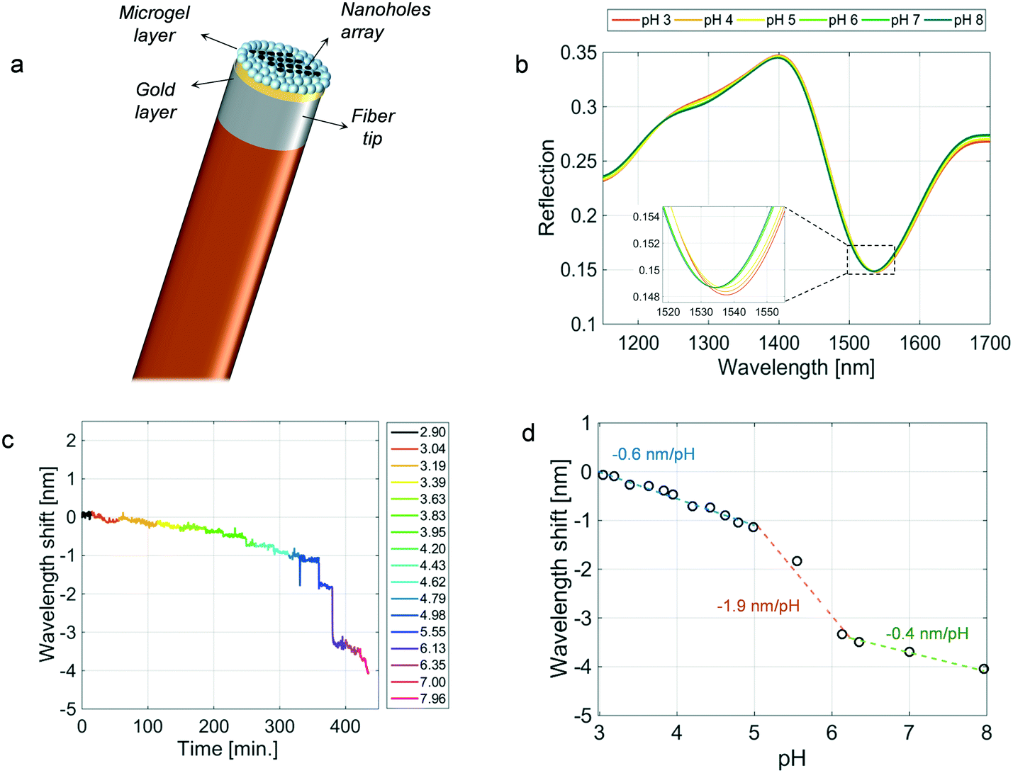 | ||
| Fig. 3 (a) Schematic of the ‘open’ LOF device. (b) Reflection spectra at different pH values. (c) Sensorgram, i.e. resonance wavelength shift as a function of time for different pH values. (d) Steady-state values reached at each pH tested. The dashed curves in (d) represent the linear fittings in three different pH ranges. | ||
The whole wavelength shift of the sensorgram shown in Fig. 3c is about −4 nm, which is more than two orders of magnitude smaller than the one obtained using the cavity-device. Beyond the sensitivity, it is interesting to observe that the response times retrieved from the sensorgram in Fig. 3c (the average values being 162, 102, and 102 seconds in the ‘lower’, ‘mid’, and ‘higher’ ranges, respectively) are in line with those achieved in the case of the ‘closed’ (cavity-enhanced) device. These results suggest that the top gold membrane realized for the formation of the optical cavity has a negligible influence on the interaction between the MG film and the aqueous solution in which the probe is immersed. It can therefore be inferred that the time dynamics are essentially affected by the relatively slow response time to solution pH changes of AAc based materials.34 The speed of the response could be significantly improved by changing the MG monomers' composition and in particular by increasing the length of the pendant acidic-alkyl chain.34 These monomers can create a lower packing density and a less dense internal MG structure, resulting in a larger interstitial space between chains and increased chain mobility and faster shrinking/swelling kinetics.
Conclusions
In conclusion, we reported on a cavity-enhanced LOF optrode for pH sensing. Sensitivities of 81 nm per pH unit, 315 nm per pH unit, and 20 nm per pH unit were observed in the pH ranges 2.9–4.6, 4.6–5.8, and 5.8–8, respectively. Overall, to the best of our knowledge, these values are the highest reported so far with optical fiber pH sensors. The high sensitivity values achieved allow for monitoring the probe response by using low-cost optical equipment, which does not require high spectral resolution capabilities. Our sensor should preferably operate under thermostatic conditions in order to avoid issues of temperature cross sensitivity (characterization results on the thermal sensitivity of our probe are provided in section S3 in the ESI†). In an application scenario where the temperature cannot be controlled, a fiber Bragg grating integrated into the same optical fiber probe, in the proximity of the tip, can be used as a valid method to continuously monitor spurious wavelength shifts induced by thermal fluctuations.23 Alternatively, it is possible to synthesize MGs that are insensitive to temperature changes by using different monomers.46–48 The results achieved in this work open the way for the development of compact optical fiber-based probes for pH monitoring to be exploited as a disposable device for all those applications that require high spatial resolutions and accurate measurements. For instance, by exploiting the biocompatibility of optical fibers and their elevated degree of integration inside catheters and needles, the presented optical fiber probe can be used for single-cell pH monitoring, such as in the case of cultured human cells, as well as for pH measurements on tissues at different locations, for on-body testing under clinical conditions (i.e., inside a wound dressing), or even in biofluids reflecting variations in the local, regional, and systemic acid–base balance related to health and disease.10Conflicts of interest
There are no conflicts to declare.References
- A. Steinegger, O. S. Wolfbeis and S. M. Borisov, Chem. Rev., 2020, 120, 12357–12489 CrossRef CAS PubMed.
- R. Bogue, Sens. Rev., 2017, 37(1), 1–6 CrossRef.
- G. K. Mani, K. Miyakoda, A. Saito, Y. Yasoda, K. Kajiwara, M. Kimura and K. Tsuchiya, ACS Appl. Mater. Interfaces, 2017, 9, 21651–21659 CrossRef CAS PubMed.
- A. G. Leal-Junior, C. A. Diaz, L. M. Avellar, M. J. Pontes, C. Marques and A. Frizera, Sensors, 2019, 19(14), 3156 CrossRef PubMed.
- P. Patel, TrAC, Trends Anal. Chem., 2002, 21, 96–115 CrossRef CAS.
- P. Dey, I. Blakey and N. Stone, Chem. Sci., 2020, 11, 8671–8685 RSC.
- G. Hao, Z. P. Xu and L. Li, RSC Adv., 2018, 8, 22182–22192 RSC.
- M. Chen, J. Wang, W. Tan, Y. Feng and G. Zheng, J. Biophotonics, 2021, 14, e202000239 CAS.
- J. Mandal, P. Ghorai, P. Brandão, K. Pal, P. Karmakar and A. Saha, New J. Chem., 2018, 42, 19818–19826 RSC.
- L. Manjakkal, S. Dervin and R. Dahiya, RSC Adv., 2020, 10, 8594–8617 RSC.
- Q. Yan, B. Peng, G. Su, B. E. Cohan, T. C. Major and M. E. Meyerhoff, Anal. Chem., 2011, 83, 8341–8346 CrossRef CAS PubMed.
- A. Tanaka, F. Utsunomiya and T. Douseki, IEEE Sens. J., 2015, 16, 3472–3479 Search PubMed.
- A. Vasudev, A. Kaushik, Y. Tomizawa, N. Norena and S. Bhansali, Sens. Actuators, B, 2013, 182, 139–146 CrossRef CAS.
- B. Schyrr, S. Pasche, E. Scolan, R. Ischer, D. Ferrario, J.-A. Porchet and G. Voirin, Sens. Actuators, B, 2014, 194, 238–248 CrossRef CAS.
- M. V. Shirmanova, I. N. Druzhkova, M. M. Lukina, M. E. Matlashov, V. V. Belousov, L. B. Snopova, N. N. Prodanetz, V. V. Dudenkova, S. A. Lukyanov and E. V. Zagaynova, Biochim. Biophys. Acta, Gen. Subj., 2015, 1850, 1905–1911 CrossRef CAS PubMed.
- X. Cheng, J. Bonefacino, B. Guan and H. Tam, Opt. Express, 2018, 26, 14610–14616 CrossRef CAS PubMed.
- M. E. Bosch, A. J. R. Sánchez, F. S. Rojas and C. B. Ojeda, Sensors, 2007, 7, 797–859 CrossRef CAS.
- D. J. Monk and D. R. Walt, Anal. Bioanal. Chem., 2004, 379, 931–945 CrossRef CAS PubMed.
- J. Rantala, J. Hännikäinen and J. Vanhala, Pers. Ubiquitous Comput., 2011, 15, 85–96 CrossRef.
- J. Gong, M. G. Tanner, S. Venkateswaran, J. M. Stone, Y. Zhang and M. Bradley, Anal. Chim. Acta, 2020, 1134, 136–143 CrossRef CAS PubMed.
- P. Zubiate, C. Zamarreño, I. Del Villar, I. Matias and F. Arregui, Sens. Actuators, B, 2016, 231, 484–490 CrossRef CAS.
- Y. Zhao, M. Lei, S.-X. Liu and Q. Zhao, Sens. Actuators, B, 2018, 261, 226–232 CrossRef CAS.
- A. Al Noman, J. N. Dash, X. Cheng, C. Y. Leong, H.-Y. Tam and C. Yu, Opt. Express, 2020, 28, 39640–39648 CrossRef CAS PubMed.
- A. Cusano, M. Consales, A. Crescitelli and A. Ricciardi, Lab-on-fiber technology, Springer, 2015 Search PubMed.
- P. Vaiano, B. Carotenuto, M. Pisco, A. Ricciardi, G. Quero, M. Consales, A. Crescitelli, E. Esposito and A. Cusano, Laser Photonics Rev., 2016, 10, 922–961 CrossRef CAS.
- M. Giaquinto, A. Aliberti, A. Micco, F. Gambino, M. Ruvo, A. Ricciardi and A. Cusano, ACS Photonics, 2019, 6, 3271–3280 CrossRef CAS.
- J. M. Vaughan, The Fabry–Perot Interferometer: History, Theory, Practice and Applications, Routledge, 2017 Search PubMed.
- Y. Gao, X. Li and M. J. Serpe, RSC Adv., 2015, 5, 44074–44087 RSC.
- L. Scherino, M. Giaquinto, A. Micco, A. Aliberti, E. Bobeico, V. La Ferrara, M. Ruvo, A. Ricciardi and A. Cusano, Fibers, 2018, 6, 72 CrossRef CAS.
- F. Colas, D. Barchiesi, S. Kessentini, T. Toury and M. L. De La Chapelle, J. Opt., 2015, 17, 114010 CrossRef.
- M. Ghorbanpour and C. Falamaki, J. Nanostruct. Chem., 2013, 3, 1–7 Search PubMed.
- A. Aliberti, A. Ricciardi, M. Giaquinto, A. Micco, E. Bobeico, V. La Ferrara, M. Ruvo, A. Cutolo and A. Cusano, Sci. Rep., 2017, 7, 14459 CrossRef CAS PubMed.
- M. Giaquinto, A. Ricciardi, A. Aliberti, A. Micco, E. Bobeico, M. Ruvo and A. Cusano, Sci. Rep., 2018, 8(1), 1–13 CAS.
- A. Ahiabu and M. J. Serpe, ACS Omega, 2017, 2, 1769–1777 CrossRef CAS PubMed.
- K. El Brahmi, M. Rawiso and J. François, Eur. Polym. J., 1993, 29, 1531–1537 CrossRef.
- B. Gu, M.-J. Yin, A. P. Zhang, J.-W. Qian and S. He, Opt. Express, 2009, 17, 22296–22302 CrossRef CAS PubMed.
- M. J. Yin, M. Yao, S. Gao, A. P. Zhang, H. Y. Tam and P. K. A. Wai, Adv. Mater., 2016, 28, 1394–1399 CrossRef CAS PubMed.
- K. Shehzad, T. Shi, A. Qadir, X. Wan, H. Guo, A. Ali, W. Xuan, H. Xu, Z. Gu and X. Peng, Adv. Mater. Technol., 2017, 2, 1600262 CrossRef.
- G. Dubourg and M. Radović, ACS Appl. Mater. Interfaces, 2019, 11, 6257–6266 CrossRef CAS PubMed.
- A. Bornheim, C. Pena, M. Spiropulu, S. Xie and Z. Zhang, Nucl. Instrum. Methods Phys. Res., Sect. A, 2017, 867, 32–39 CrossRef CAS.
- A. K. Pathak and V. K. Singh, Opt. Fiber Technol., 2017, 39, 43–48 CrossRef CAS.
- J. M. Corres, I. del Villar, I. R. Matias and F. J. Arregui, Opt. Lett., 2007, 32, 29–31 CrossRef PubMed.
- R. Gordon, D. Sinton, K. L. Kavanagh and A. G. Brolo, Acc. Chem. Res., 2008, 41, 1049–1057 CrossRef CAS PubMed.
- S. A. Maier, Plasmonics: fundamentals and applications, Springer Science & Business Media, 2007 Search PubMed.
- M. Giaquinto, A. Micco, A. Aliberti, E. Bobeico, V. La Ferrara, R. Menotti, A. Ricciardi and A. Cusano, Sensors, 2018, 18, 1119 CrossRef PubMed.
- L. Zhao, C. Xiao, G. Gai and J. Ding, Chem. Commun., 2016, 52, 7633–7652 RSC.
- C. Chen, X.-L. Zhao, Z.-H. Li, Z.-G. Zhu, S.-H. Qian and A. J. Flewitt, Sensors, 2017, 17, 182 CrossRef PubMed.
- Q. Guo, Z. Wu, X. Zhang, L. Sun and C. Li, Soft Matter, 2014, 10, 911–920 RSC.
Footnote |
| † Electronic supplementary information (ESI) available. See DOI: https://doi.org/10.1039/d1sd00071c |
| This journal is © The Royal Society of Chemistry 2022 |