 Open Access Article
SrO-layer insertion in Ruddlesden–Popper Sn-based perovskite enables efficient CO2 electroreduction towards formate†
Jing
Zhao‡
ab,
Peng
Zhang‡
ab,
Lulu
Li
ab,
Tenghui
Yuan
ab,
Hui
Gao
ab,
Gong
Zhang
 ab,
Tuo
Wang
 ab,
Zhi-Jian
Zhao
 ab and
Jinlong
Gong
 *abcd
*abcd
aSchool of Chemical Engineering & Technology, Key Laboratory for Green Chemical Technology of Ministry of Education, Tianjin University, Tianjin 300072, China. E-mail: jlgong@tju.edu.cn
bCollaborative Innovation Center for Chemical Science & Engineering (Tianjin), Tianjin 300072, China
cHaihe Laboratory of Sustainable Chemical Transformations, Tianjin 300192, China
dJoint School of National University of Singapore and Tianjin University, International Campus of Tianjin University, Binhai New City, Fuzhou 350207, China
First published on 5th July 2022
Abstract
Tin (Sn)-based oxides have been proved to be promising catalysts for the electrochemical CO2 reduction reaction (CO2RR) to formate (HCOO−). However, their performance is limited by their reductive transformation into metallic derivatives during the cathodic reaction. This paper describes the catalytic chemistry of a Sr2SnO4 electrocatalyst with a Ruddlesden–Popper (RP) perovskite structure for the CO2RR. The Sr2SnO4 electrocatalyst exhibits a faradaic efficiency of 83.7% for HCOO− at −1.08 V vs. the reversible hydrogen electrode with stability for over 24 h. The insertion of the SrO-layer in the RP structure of Sr2SnO4 leads to a change in the filling status of the anti-bonding orbitals of the Sn active sites, which optimizes the binding energy of *OCHO and results in high selectivity for HCOO−. At the same time, the interlayer interaction between interfacial octahedral layers and the SrO-layers makes the crystalline structure stable during the CO2RR. This study would provide fundamental guidelines for the exploration of perovskite-based electrocatalysts to achieve consistently high selectivity in the CO2RR.
Introduction
The electrochemical CO2 reduction reaction (CO2RR) is an attractive and sustainable approach to mitigate the greenhouse effect by storing renewable energy (e.g., solar and wind energy) in the form of chemical bonds.1–3 The CO2RR can yield a variety of valuable products, among which formate (HCOO−) shows the advantages of environmental compatibility and transportability as an important raw material.4,5 It is also a promising material for liquid hydrogen storage for fuel cell applications.5,6 HCOO− production by the CO2RR has been proved to be predominately realized by tin(Sn)-based electrocatalysts.7–12 The emerging evidence suggested that Sn oxides exhibit high activity.7,13 Besides, Sn-based electrocatalysts have the advantages of low cost, abundance in the earth's crust and environmental friendliness.7–9 Nevertheless, their selectivity to HCOO− would drop with the proceeding of the CO2RR due to their reductive transformation into metallic derivatives.14,15 Thence, there is an urgent need to design Sn-based oxides with consistently high selectivity.The electrocatalytic performance of Sn-based oxides can be promoted through compositional and structural engineering, which can tune the electrical properties and coordination stability of the active sites.16–19 For instance, N doping had been conducted to regulate the charge density of the Sn active sites in SnO2 to enhance the selectivity towards HCOO−.19 Besides, SrSnO3 has been proved to show high performance for the CO2RR to HCOO− as a result of the perovskite structure.16 However, the stability of SrSnO3 is still not satisfactory. The deactivation mechanism of such ABO3 perovskite electrocatalysts was proposed to be the surface amorphization or reconstruction during the electrocatalytic processes.20–22 Therefore, effective strategies to stabilize the crystal structures of perovskites would help further enhance the performance of Sn-based electrocatalysts. The insertion of rock-salt AO-layers in Ruddlesden–Popper (RP) perovskite not only induces interlayer interaction to stabilize the crystal structure, but also optimizes the electrical properties of the active B-site.23–26
This paper describes the design and synthesis of two-dimensional layered Sr2SnO4 with a RP structure for the selective conversion of CO2 to HCOO−. Compared with the SnO2 and SrSnO3 samples, Sr2SnO4 shows enhanced selectivity with the Faradaic Efficiency (FE) for HCOO− reaching 83.7% (−1.08 V vs. the reversible hydrogen electrode). Besides, Sr2SnO4 exhibits long-term stability for over 24 h. As revealed by the experiments and density functional theory (DFT) calculations, the SrO-layer in the RP structure is the key to achieving good performance, which could optimize the binding energy of *OCHO and promote structural stability.
Results and discussion
Structures of catalysts
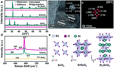
Fig. 1a shows the X-ray diffraction (XRD) patterns of SnO2, SrSnO3, and Sr2SnO4, the diffraction peaks of which are readily indexed to tetragonal SnO2 (P42mnm, JCPDS No. 41-1445), cubic SrSnO3 (Pm3m, JCPDS No. 74-1298) and tetragonal Sr2SnO4 (I4/mmm, JCPDS No. 97-002-7114), respectively. No peak corresponding to other phases was detected, demonstrating the high phase purity of SnO2, perovskite SrSnO3, and RP perovskite Sr2SnO4 catalysts. The scanning electron microscopy (SEM) images reveal the porous structures of the samples (Fig. S1†). In addition, the electron dispersive X-ray spectroscopy (EDS) mappings exhibit uniform distributions of Sr, Sn, and O elements (Fig. S2 and S3†). To further confirm the formation of the RP phase, the high-resolution transmission electron microscopy (HRTEM) image of Sr2SnO4 was collected (Fig. 1b). The observed lattice fringes with a spacing of 0.28 nm and 0.20 nm correspond to the (110) and (200) planes of Sr2SnO4. The inset shows the result of fast Fourier transform (FFT) analysis of the HRTEM image, which further confirms the tetragonal structure of Sr2SnO4. Moreover, the selected area electron diffraction (SAED) pattern of Sr2SnO4 clearly reflects the tetragonally arranged diffraction spots of the [001] zone axes (Fig. 1c), consistent with the result of the HRTEM characterization.Raman spectroscopy was used to investigate the differences in structures between the three Sn-based oxides (Fig. 1d). The bands centered at 472, 631 and 771 cm−1 of SnO2 correspond to the vibration modes of Eg, A1g, and B2g, respectively.27 The band of SrSnO3 at 399 cm−1 corresponds to SnO3 torsional mode, and the peak at 576 cm−1 is associated with Sn–O stretching vibrations, indicating the formation of [SnO6] octahedra.28,29 The band of Sr2SnO4 located at 445 cm−1 is related to the vibration of the bridge Sr–O–Sn oxygen bond axis in A1g symmetry along the c axis. This band shows the interactions between the perovskite layers and the rock-salt SrO-layers in the RP structure.30 The differences in the crystal structures of the three oxides are illustrated in Fig. 1e. For SrSnO3, Sr2+ ions occupy the A-sites, whereas Sn4+ ions form the corner-linked [SnO6] octahedra at the B-sites. Sr2SnO4 is composed of rock-salt SrO-layers and SrSnO3 perovskite layers along the crystallographic c-axis direction. This alternating layered RP structure would lead to unique structural and electrical properties, which could be beneficial for promoting electrocatalytic performance.31,32
CO2RR performance
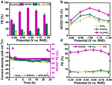
The CO2RR performance was measured in a three-electrode H-type cell, with CO2-saturated 0.5 M KHCO3 as electrolyte. The products were analysed at potentials between −0.88 and −1.28 V vs. the reversible hydrogen electrode (RHE). All the following potentials are referred to the RHE. Sr2SnO4 exhibits a stable current density of up to 30.0 mA cm−2 at −1.28 V, surpassing those of the SrSnO3 (22.9 mA cm−2) and the SnO2 (17.8 mA cm−2) electrocatalysts (Fig. S4a, S5a, and S6†). The FE for HCOO− against potential over Sr2SnO4 shows a volcano trend, which first increases from 46.5% at −0.88 V to a peak value of 83.7% at −1.08 V. It then decreases to 62.7% at −1.28 V (Fig. 2a). The FEs for HCOO− over SnO2 and SrSnO3 also show similar volcano trends (Fig. S4b and S5b†), but with much lower peak values (64.6% for SrSnO3 and 58.9% for SnO2). Besides, Sr2SnO4 also exhibits the highest HCOO− partial current density of 12.4 mA cm−2 at −1.08 V compared to SrSnO3 (9.0 mA cm−2) and SnO2 (5.9 mA cm−2) (Fig. S7†). The stability tests were performed at a consistent potential of −1.08 V (Fig. 2c). Sr2SnO4 displays no obvious decay in the current density with the FE for HCOO− maintained at about 79.0%. However, there is an obvious increase in the current density for SrSnO3 and SnO2, with a decrease in HCOO− FE at the same time. Although the selectivity of these Sn-based electrocatalysts may not reach the high value reported in some representative studies,33,34 the comparison of their performance could reflect the structural advantages of the RP perovskite. The electrocatalytic performance of Sr2SnO4 was also evaluated in a flow cell with the catalysts dispersed on a gas diffusion electrode (GDE) to enhance the mass transfer of CO2. The peak FE towards HCOO− over Sr2SnO4 is 84.5% at −0.68 V (Fig. 2d), and the current density for HCOO− reaches about 79.2 mA cm−2 at −0.88 V (Fig. S8†). Moreover, Sr2SnO4 displays long-term stability for over 50 h with the HCOO− partial current density maintained at about 59.1 mA cm−2 (Fig. S9†). The electrolyte was replaced during the chronoamperometric test to avoid the formation of (bi)carbonate salts on the diffusion layer, which caused the strong fluctuation of current density. The FEs towards H2 and CO are below 10.0% with negligible change. According to the results of the activity evaluation, the Sr2SnO4 with the RP perovskite structure achieved consistently high selectivity towards HCOO−. The performance of Sr2SnO4 is comparable to some of the state-of-the-art electrocatalysts for HCOO− production through the CO2RR (Table S1†).Operando Raman and ATR-SEIRAS spectra
To reveal the origin of the high stability of Sr2SnO4, operando Raman spectra of different samples were collected using a homemade electrochemical cell (Fig. S10†). With the decrease of the potential from −0.58 V to −1.28 V, the A1g peak of crystalline SnO2 at 631 cm−1 declines in intensity, which finally disappears after −1.08 V (Fig. 3a). This phenomenon would be caused by the reduction of SnO2 to metallic Sn at high cathodic potentials, as proved by the formation of the Sn phase after the CO2RR stability test (Fig. S11a†).14 In the operando Raman spectra of SrSnO3, the appearance of peaks at 631 cm−1 below −1.08 V suggests the surface reconstruction of SrSnO3 to form SnO2 during the CO2RR, which would then be partially reduced to metallic Sn (Fig. 3b). This result could be supported by the XRD pattern of SrSnO3 after the stability test, which clearly shows the presence of SnO2 and Sn phases (Fig. S11b†).16 In contrast, the Raman bands of Sr2SnO4 at 445 cm−1 arising from the interactions between the perovskite layer and rock-salt SrO-layer remain unchanged at different potentials, same as the bands corresponding to the [SnO6] octahedra at 576 cm−1 (Fig. 3c). These phenomena are in agreement with the end-of-test XRD pattern, showing diffraction peaks of only Sr2SnO4 (Fig. S11c†). The HRTEM and SEM images of the three Sn-based oxide catalysts after the CO2RR stability test have been characterized. There was a significant change in the morphology of SnO2 (Fig. S12a†). Such a change could be ascribed to the reduction of SnO2 to metallic Sn (Fig. S13†). Similar phenomena could also be found for SrSnO3, which could be reduced to SnO2 and Sn (Fig. S12b and S14†). However, the morphology of the Sr2SnO4 electrocatalyst was maintained after the CO2RR stability test (Fig. S12c†). Besides, the HRTEM image showed that the crystalline nature of Sr2SnO4 was maintained (Fig. S15†). EDS mappings of Sr2SnO4 after the stability test exhibit uniform distributions of Sr, Sn, and O elements (Fig. S16†). The results above demonstrate the superior stability of Sr2SnO4 during the CO2RR. The high durability of Sr2SnO4 would be induced by the SrO-layer insertion in the RP structure, which leads to the strong interaction between perovskite layers and rock-salt SrO-layers to prohibit structural deformation and reconstruction.26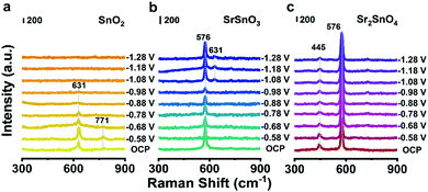 | ||
| Fig. 3 Operando Raman spectra of (a) SnO2, (b) SrSnO3 and (c) Sr2SnO4 recorded at various potentials vs. RHE in a CO2-saturated 0.5 M KHCO3 solution, respectively. | ||
In addition to good stability, the RP perovskite Sr2SnO4 electrocatalyst shows high selectivity towards HCOO−. To find the underlining mechanism of the promoted electrocatalytic performance, operando attenuated-total-reflection surface-enhanced infrared absorption spectroscopy (ATR-SEIRAS) characterization was conducted. The peaks at around 1630 cm−1 observed in all three samples can be assigned to the interfacial H2O (Fig. 4a–c).9,35 The bands at 1367–1358 cm−1, 1397–1390 cm−1 and 1390–1386 cm−1 for SnO2, SrSnO3 and Sr2SnO4 with an obvious Stark effect (peak position shifted to a lower wavenumber at more negative potentials) could be assigned to *OCHO absorbed on the surface.36,37 The *OCHO peaks of SnO2 can be observed from −0.48 V to −1.28 V. For SrSnO3, the signal of *OCHO appears at −0.68 V and disappears at −1.18 V. The signal of *OCHO was detected from −0.58 V to −0.88 V for Sr2SnO4. Since *OCHO is the essential intermediate for the generation of HCOO−,38 its rapid desorption on Sr2SnO4 would be the result of the weak adsorption of *OCHO, considering its high selectivity towards HCOO−.39,40 Therefore, the high selectivity of Sr2SnO4 would originate from the optimized binding energy of *OCHO on the surface, which might be realized by the SrO-layer insertion in the RP perovskite structure.
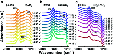 | ||
| Fig. 4 Operando ATR-SEIRAS spectra of (a) SnO2 (b) SrSnO3 and (c) Sr2SnO4 recorded at various potentials vs. RHE in a CO2-saturated 0.5 M KHCO3 solution, respectively. | ||
DFT simulations
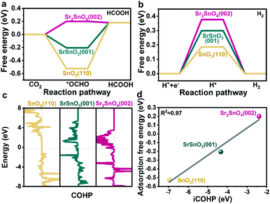
To further reveal the intrinsic role of the RP structure of Sr2SnO4 in promoting selectivity, DFT simulations were performed. Thermodynamically stable SnO2(110),41 SrSnO3(001) (Table S2†) and SrO-terminated Sr2SnO4(002) surfaces24 were chosen as the starting models for the computational study. The influence of surface vacancies, which significantly affect the surface catalytic reactions, was considered due to the relatively large energy required for the formation of bulk oxygen vacancies in these samples (Tables S3 and S4†). According to their surface phase diagrams (Fig. S17†), SnO2(110)/4ObriH*,41 SrSnO3(001)/7Ov and Sr2SnO4(002)/8Ov were found to be stable in the CO2RR process. These models were selected for the understanding of the reaction mechanism, which would represent the real active sites of the catalysts during the reaction. As shown in the well-discussed reaction pathway of the CO2RR to HCOO− (Fig. S18†), the *OCHO intermediate is formed by the hydrogenation of CO2, which subsequently produces HCOOH by the transfer of electrons and protons.41,42 The results of DFT simulations show that the formation energy of *OCHO over the Sr2SnO4(002)/8Ov surface (0.20 eV) is higher than those over the SrSnO3(001)/7Ov and the SnO2(110) (Fig. 5a). The process of *OCHO desorption to form HCOOH on Sr2SnO4(002)/8Ov is spontaneous. However, the energy barriers for *OCHO desorption over SnO2(110) and SrSnO3(001)/7Ov are around 0.70 eV and 0.39 eV. Therefore, Sr2SnO4 undergoes easy desorption of *OCHO for the CO2RR to HCOO−, which is in accordance with the results of the operando ATR-SEIRAS characterization. Besides, the ΔGH* on Sr2SnO4(002)/8Ov is higher than those on the SrSnO3(001)/7Ov and the SnO2(110) (Fig. 5b), as reflected by the relatively low selectivity towards H2 on Sr2SnO4 (Fig. 2a, S4b and S5b†). Since the thermodynamically stable SrO-layer in Sr2SnO4(002) may be involved in the reaction (Fig. S19†), its role in the CO2RR was investigated, which would also promote *OCHO generation and inhibit H2 production (Fig. S20†). These results indicate that Sr2SnO4 exhibits high selectivity due to the optimized binding strength of *OCHO.Furthermore, crystal orbital Hamilton population (COHP) analysis was conducted to explore how the SrO-layer insertion in Sr2SnO4 would affect the selectivity (Fig. 5c). The anti-bonding orbitals of Sn active sites with the O atom of *OCHO below the Fermi level (Ef) imply the weakening adsorption of *OCHO on Sn, which is most obvious on the Sr2SnO4(002) surface. Therefore, the filling of the anti-bonding orbitals leads to a reduction in the bonding strength of Sn–O, corresponding to the relatively weak adsorption strength of *OCHO on Sr2SnO4. Besides, the linear relationship between the integrated COHP (iCOHP) and ΔG*OCHO quantitatively confirms that the population of bonding/antibonding orbitals below Ef is the key factor in regulating the ΔG*OCHO (Fig. 5d).41 Therefore, the tuned electrical properties of active sites in the RP perovskite Sr2SnO4 electrocatalyst optimize the binding energy of *OCHO over Sr2SnO4(002)/8Ov, leading to the high selectivity for the CO2RR to HCOO−.
Conclusions
In summary, a Sr2SnO4 perovskite electrocatalyst with a RP structure was fabricated via a simple solid-state reaction. Sr2SnO4 exhibits high performance for the CO2RR with an FE of 83.7% towards HCOO− and long-term durability of over 24 h. The SrO-layer insertion in the RP structure leads to strong interlayer interactions, which could prohibit structural deformation and reconstruction. Thus, Sr2SnO4 possesses good stability. Besides, the anti-bonding orbital filling of the Sn active site in the RP structure results in the favorable binding strength of *OCHO on Sr2SnO4, so that it shows higher selectivity towards HCOO− than the SnO2 and the SrSnO3 control samples. Our work demonstrates that Sr2SnO4 can serve as an efficient electrocatalyst for HCOO− production through the CO2RR. The findings would guide the rational design of perovskite-based electrocatalysts and open up an avenue for tuning the catalytic selectivity and stability by structure engineering.Data availability
The data that supports the findings of this study is available from the corresponding author upon reasonable request.Author contributions
J. L. G supervised the project. P. Z. and J. Z. conceived the idea. J. Z. synthesized the catalysts and conducted the CO2RR performance tests. L. L. L conducted DFT simulations. Y. T. H., G. H., and G. Z. conducted related characterization studies. All the authors participated in the writing of the manuscript.Conflicts of interest
There are no conflicts to declare.Acknowledgements
We acknowledge the National Key R&D Program of China (2021YFA1501503), the National Natural Science Foundation of China (22121004, 22108197), the Haihe Laboratory of Sustainable Chemical Transformations (CYZC202107), the Natural Science Foundation of Tianjin City (18JCJQJC47500), the Program of Introducing Talents of Discipline to Universities (No. BP0618007) and the Xplorer Prize for financial support.References
- S. Zhang, Q. Fan, R. Xia and T. J. Meyer, Acc. Chem. Res., 2020, 53, 255–264 CrossRef CAS PubMed.
- X. Wang, Z. Wang, F. P. García de Arquer, C.-T. Dinh, A. Ozden, Y. Li, D.-H. Nam, J. Li, Y.-S. Liu, J. Wicks, Z. Chen, M. Chi, B. Chen, Y. Wang, J. Tam, J. Y. Howe, A. Proppe, P. Todorović, F. Li, T.-T. Zhuang, C. M. Gabardo, A. R. Kirmani, C. McCallum, S.-F. Hung, Y. Lum, M. Luo, Y. Min, A. Xu, C. P. O'Brien, B. Stephen, B. Sun, A. H. Ip, L. J. Richter, S. O. Kelley, D. Sinton and E. H. Sargent, Nat. Energy, 2020, 5, 478–486 CrossRef CAS.
- Y. Ling, Q. Ma, Y. Yu and B. Zhang, Trans. Tianjin Univ., 2021, 27, 180–200 CrossRef CAS.
- X. An, S. Li, X. Hao, Z. Xie, X. Du, Z. Wang, X. Hao, A. Abudula and G. Guan, Renew. Sustain. Energy Rev., 2021, 143, 110952 CrossRef CAS.
- N. Han, P. Ding, L. He, Y. Li and Y. Li, Adv. Energy Mater., 2020, 10, 1902338 CrossRef CAS.
- S. Agarwal, Y. Zhai, D. Hill and N. Sridhar, ChemSusChem, 2011, 4, 1301–1310 CrossRef PubMed.
- Y. Chen and M. W. Kanan, J. Am. Chem. Soc., 2012, 134, 1986–1989 CrossRef CAS PubMed.
- R. Daiyan, E. C. Lovell, N. M. Bedford, W. H. Saputera, K.-H. Wu, S. Lim, J. Horlyck, Y. H. Ng, X. Lu and R. Amal, Adv. Sci., 2019, 6, 1900678 CrossRef CAS PubMed.
- W. Deng, L. Zhang, L. Li, S. Chen, C. Hu, Z.-J. Zhao, T. Wang and J. Gong, J. Am. Chem. Soc., 2019, 141, 2911–2915 CrossRef CAS PubMed.
- H. Li, N. Xiao, Y. Wang, C. Liu, S. Zhang, H. Zhang, J. Bai, J. Xiao, C. Li, Z. Guo, S. Zhao and J. Qiu, J. Mater. Chem. A, 2020, 8, 1779–1786 RSC.
- S. Lee, H. Ju, R. Machunda, S. Uhm, J. K. Lee, H. J. Lee and J. Lee, J. Mater. Chem. A, 2015, 3, 3029–3034 RSC.
- N. Han, Y. Wang, J. Deng, J. Zhou, Y. Wu, H. Yang, P. Ding and Y. Li, J. Mater. Chem. A, 2019, 7, 1267–1272 RSC.
- C. Liang, B. Kim, S. Yang, Y. Liu, C. F. Woellner, Z. Li, R. Vajtai, W. Yang, J. Wu, P. J. A. Kenis and P. M. Ajayan, J. Mater. Chem. A, 2018, 6, 10313–10319 RSC.
- A. Dutta, A. Kuzume, M. Rahaman, S. Vesztergom and P. Broekmann, ACS Catal., 2015, 5, 7498–7502 CrossRef CAS.
- R. Daiyan, X. Lu, Y. H. Ng and R. Amal, Catal. Sci. Technol., 2017, 7, 2542–2550 RSC.
- Y. Pi, J. Guo, Q. Shao and X. Huang, Nano Energy, 2019, 62, 861–868 CrossRef CAS.
- X. An, S. Li, A. Yoshida, T. Yu, Z. Wang, X. Hao, A. Abudula and G. Guan, ACS Appl. Mater. Interfaces, 2019, 11, 42114–42122 CrossRef CAS PubMed.
- G. Wen, B. Ren, M. G. Park, J. Yang, H. Dou, Z. Zhang, Y.-P. Deng, Z. Bai, L. Yang, J. Gostick, G. A. Botton, Y. Hu and Z. Chen, Angew. Chem., Int. Ed., 2020, 59, 12860–12867 CrossRef CAS PubMed.
- C. Hu, L. Zhang, L. Li, W. Zhu, W. Deng, H. Dong, Z.-J. Zhao and J. Gong, Sci. China Chem., 2019, 62, 1030–1036 CrossRef CAS.
- N. Tsvetkov, Q. Lu, L. Sun, E. J. Crumlin and B. Yildiz, Nat. Mater., 2016, 15, 1010–1016 CrossRef CAS PubMed.
- Y. Chen, H. Li, J. Wang, Y. Du, S. Xi, Y. Sun, M. Sherburne, J. W. Ager III, A. C. Fisher and Z. J. Xu, Nat. Commun., 2019, 10, 572 CrossRef CAS PubMed.
- X. Xu, Y. Chen, W. Zhou, Z. Zhu, C. Su, M. Liu and Z. Shao, Adv. Mater., 2016, 28, 6442–6448 CrossRef CAS PubMed.
- J. Wang, C. Cheng, B. Huang, J. Cao, L. Li, Q. Shao, L. Zhang and X. Huang, Nano Lett., 2021, 21, 980–987 CrossRef CAS PubMed.
- Y. Zhu, H. A. Tahini, Z. Hu, J. Dai, Y. Chen, H. Sun, W. Zhou, M. Liu, S. C. Smith, H. Wang and Z. Shao, Nat. Commun., 2019, 10, 149 CrossRef PubMed.
- C. Zhu, H. Tian, B. Huang, G. Cai, C. Yuan, Y. Zhang, Y. Li, G. Li, H. Xu and M.-R. Li, Chem. Eng. J., 2021, 423, 130185 CrossRef CAS.
- L.-F. Huang, N. Z. Koocher, M. Gu and J. M. Rondinelli, Chem. Mater., 2018, 30, 7100–7110 CrossRef CAS.
- S. Sun, G. Meng, G. Zhang, T. Gao, B. Geng, L. Zhang and J. Zuo, Chem. Phys. Lett., 2003, 376, 103–107 CrossRef CAS.
- M. Muralidharan, V. Anbarasu, A. Elaya Perumal and K. Sivakumar, J. Mater. Sci.: Mater. Electron., 2017, 28, 4125–4137 CrossRef CAS.
- U. Kumar and S. Upadhyay, J. Electron. Mater., 2019, 48, 5279–5293 CrossRef CAS.
- A. Magrez, M. Cochet, O. Joubert, G. Louarn, M. Ganne and O. Chauvet, Chem. Mater., 2001, 13, 3893–3898 CrossRef CAS.
- R. P. Forslund, W. G. Hardin, X. Rong, A. M. Abakumov, D. Filimonov, C. T. Alexander, J. T. Mefford, H. Iyer, A. M. Kolpak, K. P. Johnston and K. J. Stevenson, Nat. Commun., 2018, 9, 3150 CrossRef PubMed.
- G. Nirala, D. Yadav and S. Upadhyay, J. Adv. Ceram., 2020, 9, 129–148 CrossRef CAS.
- Y. Hori, H. Wakebe, T. Tsukamoto and O. Koga, Electrochim. Acta, 1994, 39, 1833–1839 CrossRef CAS.
- K. Bejtka, J. Zeng, A. Sacco, M. Castellino, S. Hernández, M. A. Farkhondehfal, U. Savino, S. Ansaloni, C. F. Pirri and A. Chiodoni, ACS Appl. Energy Mater., 2019, 2, 3081–3091 CrossRef CAS.
- W. Thornton and P. G. Harrison, J. Chem. Soc., Faraday Trans., 1975, 71, 461–472 RSC.
- Y. Katayama, F. Nattino, L. Giordano, J. Hwang, R. R. Rao, O. Andreussi, N. Marzari and Y. Shao-Horn, J. Phys. Chem. C, 2018, 123, 5951–5963 CrossRef.
- Y. Liang, W. Zhou, Y. Shi, C. Liu and B. Zhang, Sci. Bull., 2020, 65, 1547–1554 CrossRef CAS.
- J. E. Pander, M. F. Baruch and A. B. Bocarsly, ACS Catal., 2016, 6, 7824–7833 CrossRef CAS.
- S. Zhu, B. Jiang, W.-B. Cai and M. Shao, J. Am. Chem. Soc., 2017, 139, 15664–15667 CrossRef CAS PubMed.
- J. Heyes, M. Dunwell and B. Xu, J. Phys. Chem. C, 2016, 120, 17334–17341 CrossRef CAS.
- L. Li, Z.-J. Zhao, C. Hu, P. Yang, X. Yuan, Y. Wang, L. Zhang, L. Moskaleva and J. Gong, ACS Energy Lett., 2020, 5, 552–558 CrossRef CAS.
- J. S. Yoo, R. Christensen, T. Vegge, J. K. Nørskov and F. Studt, ChemSusChem, 2016, 9, 358–363 CrossRef CAS PubMed.
Footnotes |
| † Electronic supplementary information (ESI) available. See https://doi.org/10.1039/d2sc03066g |
| ‡ These authors contributed equally to this work. |
| This journal is © The Royal Society of Chemistry 2022 |

