
 Open Access Article
 This Open Access Article is licensed under a Creative Commons Attribution-Non Commercial 3.0 Unported Licence
Assembly, structure and thermoelectric properties of 1,1′-dialkynylferrocene ‘hinges’†
Luke A.
Wilkinson‡
 ab,
Troy L. R.
Bennett‡
a,
Iain M.
Grace‡
c,
Joseph
Hamill‡
d,
Xintai
Wang‡
ce,
Sophie
Au-Yong
c,
Ali
Ismael
c,
Samuel P.
Jarvis
c,
Songjun
Hou
c,
Tim
Albrecht
d,
Lesley F.
Cohen
e,
Colin
Lambert
*c,
Benjamin J.
Robinson
*c and
Nicholas J.
Long
*a
ab,
Troy L. R.
Bennett‡
a,
Iain M.
Grace‡
c,
Joseph
Hamill‡
d,
Xintai
Wang‡
ce,
Sophie
Au-Yong
c,
Ali
Ismael
c,
Samuel P.
Jarvis
c,
Songjun
Hou
c,
Tim
Albrecht
d,
Lesley F.
Cohen
e,
Colin
Lambert
*c,
Benjamin J.
Robinson
*c and
Nicholas J.
Long
*a
aDepartment of Chemistry, Imperial College London, MSRH, White City, London, W12 0BZ, UK. E-mail: n.long@imperial.ac.uk
bDepartment of Chemistry, University of York, Heslington, York, YO10 5DD, UK
cPhysics Department, Lancaster University, Lancaster, LA1 4YB, UK
dDepartment of Chemistry, Birmingham University, Edgbaston, Birmingham, B15 2TT, UK
eThe Blackett Laboratory, Imperial College London, South Kensington Campus, London, SW7 2AZ, UK
First published on 27th June 2022
Abstract
Dialkynylferrocenes exhibit attractive electronic and rotational features that make them ideal candidates for use in molecular electronic applications. However previous works have primarily focussed on single-molecule studies, with limited opportunities to translate these features into devices. In this report, we utilise a variety of techniques to examine both the geometric and electronic structure of a range of 1,1′-dialkynylferrocene molecules, as either single-molecules, or as self-assembled monolayers. Previous single molecule studies have shown that similar molecules can adopt an ‘open’ conformation. However, in this work, DFT calculations, STM-BJ experiments and AFM imaging reveal that these molecules prefer to occupy a ‘hairpin’ conformation, where both alkynes point towards the metal surface. Interestingly we find that only one of the terminal anchor groups binds to the surface, though both the presence and nature of the second alkyne affect the thermoelectric properties of these systems. First, the secondary alkyne acts to affect the position of the frontier molecular orbitals, leading to increases in the Seebeck coefficient. Secondly, theoretical calculations suggested that rotating the secondary alkyne away from the surface acts to modulate thermoelectric properties. This work represents the first of its kind to examine the assembly of dialkynylferrocenes, providing valuable information about both their structure and electronic properties, as well as unveiling new ways in which both of these properties can be controlled.
Introduction
Ferrocene exhibits a number of interesting properties that make it an attractive candidate for applications in molecular electronics, including high-stability, well-defined redox chemistry, and a wide variety of techniques for its functionalisation. For these reasons, myriad works have used ferrocene as a building block in the construction of both single-molecule and ensemble electronic devices.1–3 These works have subsequently uncovered interesting applications in switching,4–8 charge storage,9–14 rectification15–19 and sensing.20–25In the design of molecular wires, ferrocene insertion (and more widely the insertion of metal centres) has been shown to increase molecular conductance.26–29 In addition, recent studies of the 1,1′-dialkynylferrocene motif have shown that by controlling the rotation around the iron-cyclopentadienyl axis, through the use of a mechanical modulation, the conductance of a ferrocene can be switched between multiple states, as a function of the angle that separates the two alkynyl substituents.30,31 This indicates that the inclusion of ferrocene into a highly-conjugated architecture offers an attractive route towards optimising and increasing the functionality of organic molecular wires.32
With a view to translating these properties to the macroscale, here we study the electronic properties of self-assembled monolayers (SAMs) of ferrocene-based molecules, which could be translated to a device architecture in a relatively facile manner.33,34 To date, the majority of studies of highly-conjugated ferrocenyl SAMs have utilised ferrocene as a terminal group, ignoring the potential benefits of incorporating ferrocene into the backbone of a molecular wire.35–39 In contrast, the present study focusses on 1,1′-dialkynyl ferrocenes, which possess a relatively rigid ‘hinge-like’ structure, where the two substituents can independently rotate around a central ferrocenyl node. This offers the possibility of exploring a variety of distinct conformations which could be used to control the electronic properties of their assembled materials.
In the following study, we selected a range of 1,1′-dialkynylferrocene molecules (1–5, Fig. 1) containing different anchor-group configurations. We examined the conformational features of these systems through a combination of single molecule (STM-BJ) and ensemble (AFM and XPS) measurements, as well as through an examination of theoretically derived geometries. Where previous single-molecule studies have shown that an ‘open’ conformation (where the alkynes point in different directions) is achievable, here we have shown that the ‘hairpin’ conformation (where the alkynes point in the same direction) is generally favoured.30,31 Further to this we examined the thermoelectric features of this ‘hairpin’ structure, and unearthed an interesting feature whereby only one, of a possible two, anchor groups binds to a surface, while the alignment of the second, unbound anchor group, also subtly controls the electronic properties of the materials.
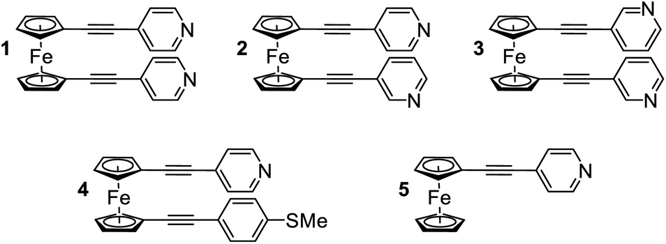 | ||
| Fig. 1 Molecules studied in this work. | ||
Results and discussion
Synthesis
The synthesis and solution based optoelectronic properties of molecules 1–5 have previously been discussed, and we refer the reader to a recent publication for more details.40Single molecule conductance measurements
Initially, scanning tunnelling microscopy (STM) break junction (BJ) measurements were employed to determine the most probable single-molecule conductances of molecules 1–4.41,42 After collecting and screening the data, a total of 706 traces for molecule 1 and 1959 traces for molecule 2 were taken forward for further analysis. It was not possible to observe features that could be attributed to the formation of genuine molecular junctions in our experiments on 3 and 4. Representative conductance traces are provided in Fig. 2(a) in which the molecular plateaus indicate a reduction in single-molecule conductance between 1 and 2, as illustrated by the 1D conductance histograms in Fig. 2(b). The histograms exhibit a peak at the conductance values, where the traces most frequently displayed a plateau. For instance, in each histogram there was a peak at 100G0, caused when the traces plateaued during the quantized atomic Au–Au contact, as well as a peak at approximately 10−6G0 caused by the instrument noise. For each histogram, the peak caused by the molecular plateaus was fitted to a Gaussian distribution to yield the most probable single-molecule conductances, which were found to be 10−4G0 for 1, and 10−5G0 for 2. For molecule 1 in particular, this conductance aligns well with literature values for similar ferrocenyl systems.26,30,31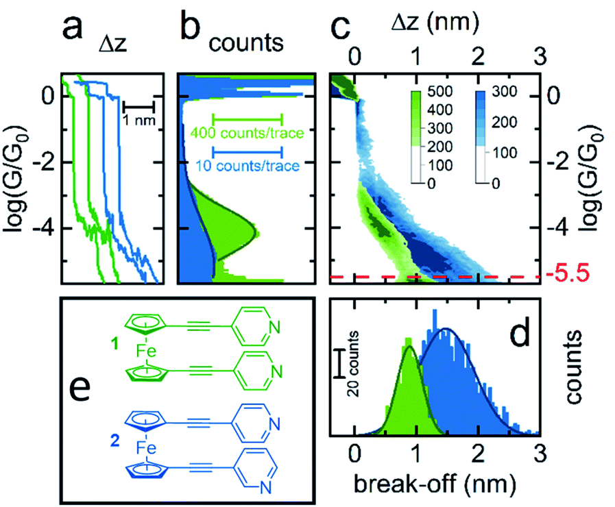 | ||
| Fig. 2 STM-BJ results. (a) Example conductance traces for 1 (green) and 2 (blue) vs. electrode displacement, (b) 1D conductance histograms with Gaussian fit for data sets of 1 (706 traces) and 2 (1959 traces), (c) 2D conductance–displacement histograms, (d) break-off distance histograms with Gaussian fits and (e) colour coded structures of 1 and 2. | ||
To obtain a more detailed understanding of the geometry and junction progression of the molecular break junctions, the displacement (Δz) of each trace was offset to 0.0 nm at 10−0.3G0, a point just after the rupture of the Au–Au junction, and all the traces in each data set were accumulated into the 2D conductance–displacement histograms of Fig. 2(c). From this, it was evident that molecule 1 produced regular traces with very reproducible molecular conductances and plateau lengths, whereas the traces for 2 were less regular with a broader distribution of plateau lengths. The most probable break off distance (BOD) was used to quantify this. To determine the BOD, the lengths of each trace, from just after the rupture of the Au–Au junction until just before the conductance reached the instrumental limit of 10−5.5G0, were accumulated into the BOD histogram shown in Fig. 2(d).
Molecule 1 yielded a symmetric and Gaussian-like BOD histogram, indicative of plateau lengths influenced predominately by a single, regular cause. Typically, this should relate to the molecular length.43 However the mean BOD for 1 was approximately 0.9 nm, just over half the expected total molecular length. For example, previously reported crystal structures of 1, measuring the distance from nitrogen to nitrogen, show this value to be approximately 1.7 nm.44–46 This suggests that either the linear molecule occupied an acute bonding angle between the two Au electrodes, or alternatively, that the molecule preferred to adopt a ‘hairpin’ conformation on the substrate, in which the two pyridine groups are oriented towards the substrate, with either one or both of the pyridine groups binding to the substrate, and the central metallocene unit is contacted by the tip, rather than a more open structure in which the tip and substrate each contact a separate pyridine group.
The 2D conductance–displacement histogram for molecule 2, in Fig. 2(c), showed molecular plateaus which were both longer than those shown by molecule 1, and were also highly sloped. For molecule 2 it is interesting to note that there appears to be a ‘shoulder’ in the 2D-conductance histogram, focused at ∼10−3G0. We performed a clustering analysis of 16![[thin space (1/6-em)]](https://www.rsc.org/images/entities/char_2009.gif) 000 traces produced from the measurement of this molecule to elucidate further information on the junction progression (as described in the ESI†). This provided little evidence for the formation of distinct sub-populations however. Interestingly, this ‘shoulder’ was universally present in each of our derived clusters, suggesting that this feature does not relate to a separate event class, and rather appears to represent a metastable geometry which occurs before the junction elongates to its final geometry.
000 traces produced from the measurement of this molecule to elucidate further information on the junction progression (as described in the ESI†). This provided little evidence for the formation of distinct sub-populations however. Interestingly, this ‘shoulder’ was universally present in each of our derived clusters, suggesting that this feature does not relate to a separate event class, and rather appears to represent a metastable geometry which occurs before the junction elongates to its final geometry.
Previously it has been suggested that highly sloped molecular plateaus can result from mechanical manipulation, i.e., opening of the dihedral angle, in conformationally flexible analytes.47 Though it was noteworthy that molecule 2 exhibited this behavior, while molecule 1 did not. It is also possible that the meta-positing of the anchor in molecule 2, being misaligned with the molecular backbone, causes coupling with the substrate to become more sensitive during junction elongation.48 This argument would appear to explain the disparity between molecules 1 and 2. Finally, as suggested in the following sections, it is possible that when the molecules are adsorbed onto the substrate, that they are assuming a tilted geometry. Indeed, it appears that as the junction is elongated, the conductance fell of as G ∝ sin4θ, suggesting that a lateral coupling of the molecular orbitals to the substrate has been broken.49 Without drawing a firm conclusion, each of these possibilities would, to different degrees, be poorly controlled during junction elongation, and could result in less regularity between traces, as was observed in the distribution of traces for molecule 2.
Molecular structure and geometry
To better understand the features observed in the STM experiments, DFT calculations were carried out to reveal the preferred geometries of 1,1′-dialkynylferrocenes. Generally, the rotational barrier for a ferrocene unit is small,50 and so the angle between the arms of molecules 1–4 could potentially adopt any value ranging from a ‘hairpin’ geometry, where the two arms lie directly on top of each other (θ = 144°, Fig. 3), to the fully extended molecule where the arms are on opposite sides (θ = 0°, Fig. 3). Using density functional theory, the optimum geometry of each of the molecules was calculated. The ground state energy of the molecules was then calculated as a function of angle θ, for molecule 1, and it was found that the minimum energy occurred at θ = 126°, with the molecule held in a ‘hairpin’ configuration with the arms slightly displaced, consistent with π–π type interactions between the two alkynyl substituents. The local minimum for the open configuration occurred at θ = 144° at an energy of 0.7 eV above the minimum. This behaviour agrees with the reported crystal structures of 1 and 3, suggesting that ferrocene molecules prefer to inhabit a closed conformation, at least in the solid-state.44–46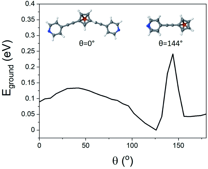 | ||
| Fig. 3 Angle of internal rotation (θ) vs. energy for molecule 1, illustrative geometries inset. | ||
SAM formation
In an attempt to exploit and study this ‘hairpin’ conformation, efforts were made to assemble these molecules onto a surface and evaluate their structures. For this purpose, self-assembled monolayers (SAMs) of molecules 1–5 were grown on freshly prepared, template stripped Au surfaces, and characterised by atomic force microscopy (AFM, see ESI† for detailed procedures relating to SAM growth and characterisation).Unlike the other analytes, compound 2 did not form good-quality uniform SAMs, exhibiting pinholes in the film that affected the conductance measured with AFM. This is likely attributable to competitive binding of the different anchor groups contained within this molecule. The other systems all formed high-quality SAMs however. The thickness of these SAMs was determined by a nano-scratching technique,51,52 and was found to be a consistent 0.65–1.00 nm for molecules 1, 4 and 5. This is in agreement with the break-off distance observed for molecule 1 in the STM-BJ measurements and suggests that (i) the molecular geometry is comparable for the single molecule and SAM measurements and (ii) molecules 1 and 4 bind in a hairpin-type conformation, as if the molecules were ‘open’ then they would have possessed a larger thickness than molecule 5, which contained only one anchor group. Molecule 3 formed a thinner SAM, with a thickness between 0.45 and 0.70 nm. This once again suggested a hairpin geometry, with the decrease in film thickness of this SAM indicating a different binding orientation for this molecule. This is likely, because molecules 1, 4 and 5 can adopt a largely perpendicular orientation, whereas 3 would present a tilted geometry, resulting from the meta-positioning of the nitrogen atoms contained within its terminal pyridyl rings.
AFM imaging was employed to determine the average roughness of SAMs 1, 3, 4 and 5 (across several spots of the sample). The roughness was in the range of 0.15–0.30 nm (Table 1), and this value was similar to the underlying TS gold substrates (0.10–0.20 nm), which confirms the SAMs uniformity. To better elucidate these results Fig. 4 shows the topography of a SAM of molecule 1, after nanoscratching, as well as thickness distributions of SAMs of 1, 3, 4 and 5, garnered from the nanoscratching analysis.
| SAMs | Roughness (nm) | Thickness (nm) | Log(G/G0) | Std (%) | S (μV K−1) | Std (μV K−1) | PF (a(W K−2)) |
|---|---|---|---|---|---|---|---|
| 1 | 0.09 | 0.81 | −4.6 | 5.4 | −16.4 | 4.1 | 0.52 |
| 3 | 0.07 | 0.52 | −3.9 | 6.5 | −7.4 | 3.5 | 0.53 |
| 4 | 0.10 | 0.79 | −4.5 | 4.8 | −9.6 | 2.2 | 0.22 |
| 5 | 0.14 | 0.82 | −4.7 | 7.1 | −9.0 | 3.1 | 0.12 |
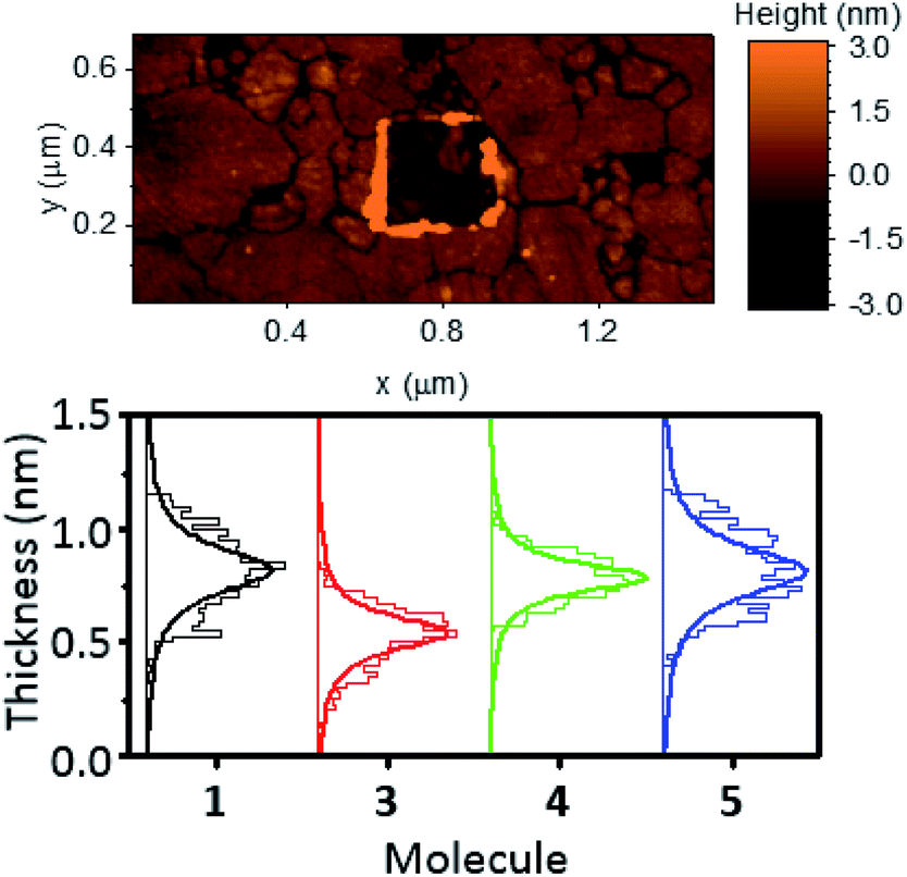 | ||
| Fig. 4 Topography of a SAM of 1 after nano-scratching (top), and thickness distributions of SAMs of 1, 3, 4 and 5 obtained from nano-scratching (bottom). | ||
X-ray photoelectron spectroscopy
In order to investigate the chemical binding of these ferrocenyl SAMs, monolayer films consisting of the symmetric molecule 1, asymmetric molecule 2, and single linker molecule 5 were studied with X-ray photoelectron spectroscopy (XPS). Although the poor uniformity of SAM 2 prevented thermoelectric measurement with AFM, the sample could still be studied with XPS by measuring over a large spot size (350 μm), enabling us to average over the poor nanoscale ordering of 2. Fig. 5(a) and (b) show spectra of the N 1s region for SAMs of 1 and 2, respectively. In each case, clear features are observed that arise from the nitrogen atoms present in the pyridine anchor groups. For the SAM of molecule 1, a fitting analysis revealed two distinct peaks located at 400.2 eV and 399.3 eV respectively, with a ratio of peak areas close to 1:1. The 399.3 eV peak can be attributed to an unbound pyridine with a deprotonated nitrogen.53–56 The peak at 400.2 eV has been previously attributed to the pyridine group binding to the gold surface.57 To confirm this assignment we carried out XPS on monolayer and multilayer SAMs of molecule 5, in which the pyridine groups should be either fully bound or unbound, respectively. The results, shown in Fig. 5(c) and (d), confirm the assignments above, with the monolayer SAM of 5 exhibiting a single bound peak at 400.2 eV, and the multilayer SAM of 5 a dominant unbound peak at 399.3 eV. The fitting analysis for the SAM of 2, shown in Fig. 5(b), results in the same near 1:1 ratio of bound and unbound nitrogen at 400.1 eV and 399.4 eV respectively. The near 1:1 ratio and consistency between SAMs of 1 and 2 strongly suggested that only one of a possible two anchor groups chemically binds to the surface in each case. It was also observed that the bound nitrogen peak was broader than the unbound peak, which we attribute to multiple chemical states merging into one peak due to the presence of multiple binding sites on the gold surface.
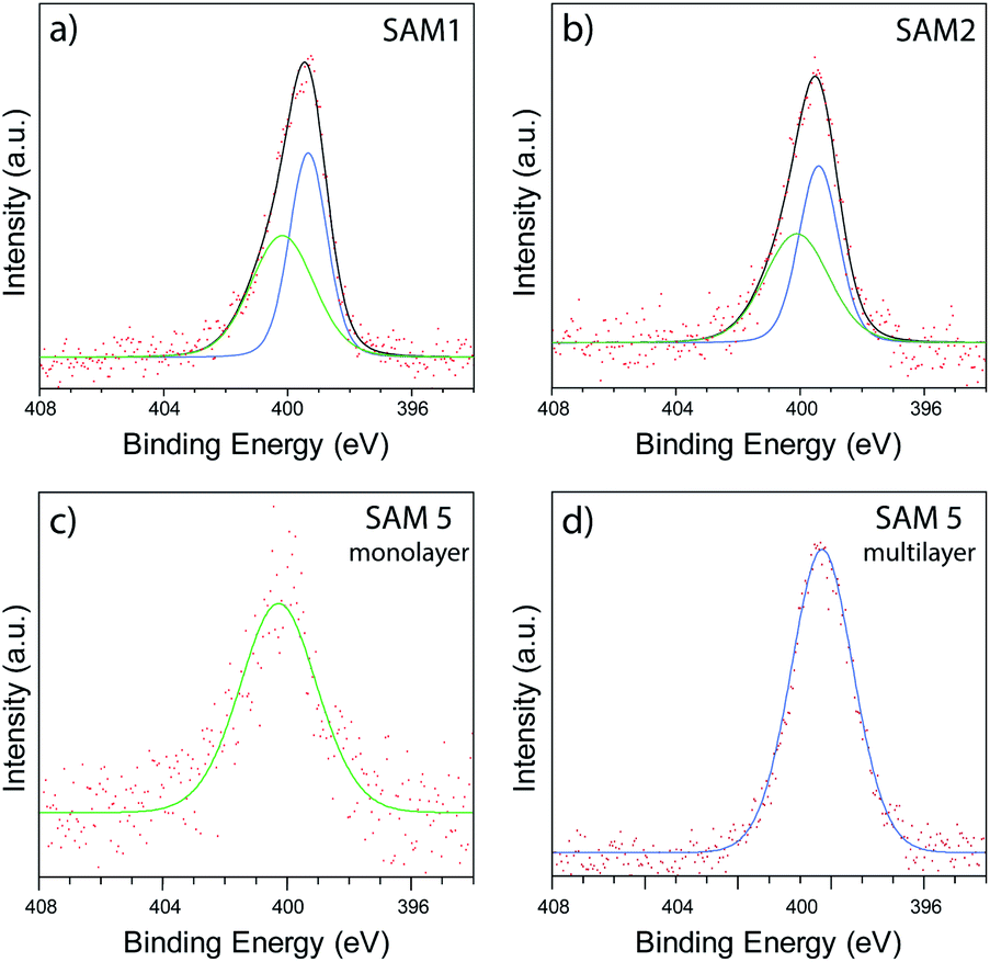 | ||
| Fig. 5 XPS data collected in the N 1s region of SAMs of 1 (a), 2 (b), monolayer SAM of 5 (c), and multilayer SAM of 5 (d). | ||
To gain greater insight into the location of the pyridine groups within the molecular film, we performed angle resolved XPS (ARXPS) on SAMs of 1 (see ESI, Section 4.3†). In order to reduce any possibility of water contamination, which would introduce additional peaks in the N 1s region,58 the film was annealed under UHV conditions at 160 °C for 12 hours prior to the ARXPS measurements, resulting in a slight shift of the bound and unbound peaks to 400.4 eV and 399.0 eV respectively. The subsequent ARXPS data collected at angles of emission of 0° and 70° are shown in Fig. S27(a) and (b),† respectively. We found that the N 1s peak at both angles could be fitted with near identical peak components, with no evidence to suggest any reduction in peak area upon rotating the sample. The similarity in peak area therefore suggested that the two nitrogen species were located at similar heights (within a surface roughness of ∼0.3 nm), supporting the formation of a ‘hairpin’ geometry. In contrast, if the upright configuration were instead present, a Beer–Lambert approximation estimates that the attenuation of the bound nitrogen signal would be >5, resulting in substantial reduction in the bound N 1s peak. This estimate assumes an inelastic mean free path of ∼1.5 nm and a nitrogen depth of ∼2.0 nm.
Thermoelectric properties
To further examine the effects of our different anchor group configurations the thermoelectric properties of the SAMs were probed. First, their electron transport properties were determined by conductive AFM (cAFM), where the number of molecules under the probe was estimated from the contact area between the probe and sample surface using the RKJ model (see ESI†). The statistics of the IV curves are shown in ESI Fig. S24† with conductance distribution histograms shown in Fig. 6 (top), and the results summarised in Table 1.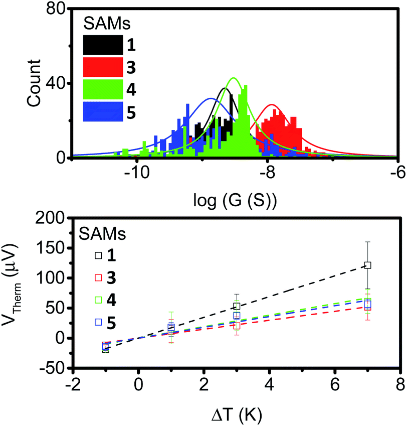 | ||
| Fig. 6 Conductance distribution (top) and plots of thermal voltage vs. ΔT (bottom) for SAMs of 1, 3, 4 and 5. | ||
It is clear from the data that the conductance values for 3 are larger than those of the other analogues, which is presumably a result of the thinner SAM, and by extension, the shorter distance between the probe and the underlying metal–substrate. For the SAMs of 1, 4 and 5, the observed conductance values were very similar. This suggests little influence is imposed on the conductive behaviour of these molecules by the presence of a second alkyne.
The thermopower of these SAMs was also investigated using a Peltier stage under the sample to create a temperature difference, ΔT, between the sample and the probe. The thermo-voltage caused by ΔT, Vtherm, between the sample and the probe was measured at 4 different ΔT points, fitted with a linear curve, and the slope of the curve,  was used to calculate the Seebeck coefficient of the junction through use of eqn (1);
 | (1) |
The results are displayed in Fig. 6 (bottom) and summarised in Table 1. All of the SAMs possessed negative Seebeck coefficients, which suggests LUMO dominated electron transport through these molecules, as has often been reported for systems with pyridine anchors connecting to a metal surface.59–62 It should be noted for molecule 4 that this point alone is not a direct indicator of sole nitrogen binding, as thioethers have previously been shown to give both positive and negative Seebeck coefficients.60,63–65 The Seebeck coefficient for 1 is −16.4 μV K−1, and is much larger than the other compounds, which themselves have values between −7 and −10 μV K−1. This suggests that the unbound alkyne of this system is acting to tune the energy of the LUMO, with respect to the Fermi-energy of the electrode. Finally, the power-factors (PF, which is equal to G × S2) were considered. The increase in Seebeck coefficient of molecule 1, and the increase in conductance of molecule 3, both granted SAMs with higher power factors than those observed in the SAMs of molecules 4 and 5.
Quantum transport calculations
The theoretical behaviour of molecules 1, 3, 4 and 5 was investigated in a SAM contacted to gold electrodes. Using the density functional code SIESTA66 and the quantum transport code GOLLUM we calculated the transmission coefficient T(E) and Seebeck coefficient S and explored how the geometry of the individual molecules controlled both S and their electrical conductance G.67The following approach was used for each calculation of molecules on a gold (111) surface. The system was periodic in 2 directions and the spacing between molecules was chosen to be 1.4 nm and 1.0 nm in the x and y directions respectively. The binding between the top contact and the Cp (cyclopentadienyl) backbone of the ferrocene unit had an optimum value of −0.34 eV, at a separation of 0.32 nm. The optimum binding geometry through the pyridine unit, in the case of the para-connection (1, 4 and 5) was found to give an Au–N distance = 2.55 Å, and the molecule was normal to the gold surface (φ = 0°). For molecule 3, with the meta-connected pyridine, the pyridine was found to bind normally to the surface as for the para case. However, as the alkynyl ‘arms’ are attached in the meta-position, there is a reduction in the height of the molecule (Fig. S16†). Therefore 3 forms a thinner SAM, in agreement with the measured value in Table 1. This may also explain why molecule 2 does not form a SAM, due to the competing behaviour of the two anchor groups.
Looking at molecule 1, and guided by the XPS data, which shows that only one arm of the molecule is attached via a pyridine anchor group, we investigated the role that the second arm plays in controlling the transport properties of this molecule, by rotating this arm through 72° away from the fully closed configuration (θ = 144°). The second pyridine was contacted to the gold surface at an identical distance, but the nitrogen atom was not above a gold atom (and is therefore unbound). Fig. 7 (right) shows that both the conductance and Seebeck are increased when both anchor groups are in contact and decreases as one arm is rotated away. This behaviour can be attributed to a broadening and shifting of the LUMO resonance (Fig. S15†).
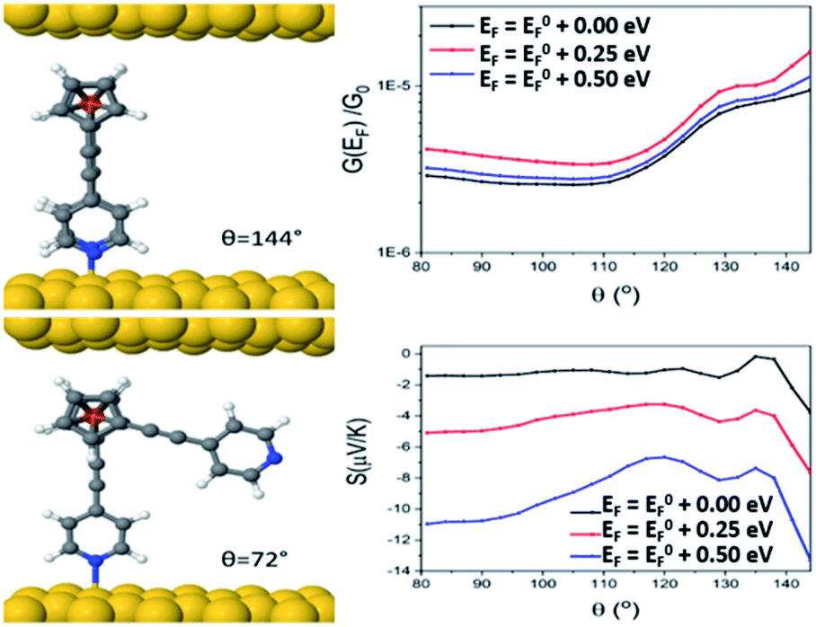 | ||
| Fig. 7 Junction geometry of molecule 1 for two different arm rotations (θ = 144° and θ = 72°, left), and conductance and Seebeck coefficients of molecule 1, as a function of arm rotation angle (θ, right). | ||
These calculations indicated that the molecular length of the ‘closed’ configuration is approximately 1 nm for molecules 1 and 5, which is slightly larger than the measured SAM thickness (Table 1). This suggests another possible configuration, in which the molecules are tilted away from the normal, thereby reducing the height and preventing the second anchor group from making contact with the bottom electrode. Following this, the transport behaviour of molecules 1, 3, 4 and 5 were investigated for tilt angles of φ = 0, 40 and 60°. Fig. 8 shows the transmission data T(E) for φ = 60°. Here, the behaviour of the transmission in the HOMO–LUMO gap shows that molecule 3 (red line) has the highest value at the Fermi energy (0 eV), due to the geometry of this system, where the reduced separation between the gold electrodes gives a larger coupling between the molecule and gold surfaces. The Fermi energy is also shifted further away from the LUMO resonance in comparison to molecule 1. Molecule 5 (blue) and molecule 1 (black) show very similar transmission curves, giving similar values for the conductance at the Fermi energy (2.3 × 10⁻⁴G0). The measured conductance of molecule 1 is similar to that of molecule 5. Therefore, this theoretical result suggests that the second arm is not in contact with the gold and is in agreement with the XPS data. The trend of these conductances are in reasonable agreement with the measured values (Table 1), and similar behaviour is found at the other tilt angles of φ = 0 and 40° (shown in Fig. S20 and S21 of the ESI†).
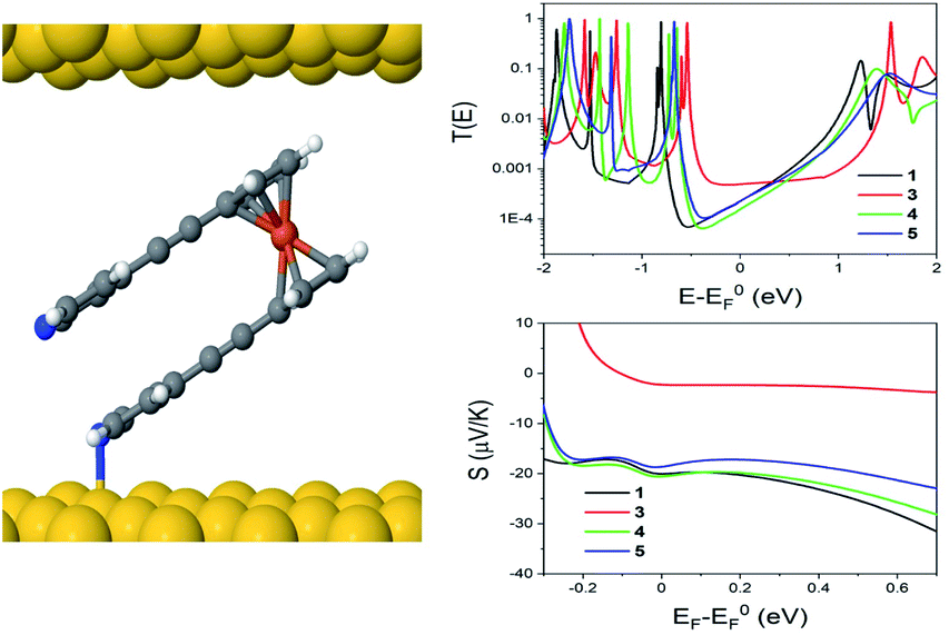 | ||
| Fig. 8 Junction geometry for molecule 1, when φ = 60° (left), as well as computed zero bias transmission coefficient (T(E)) and Seebeck coefficient (S), as a function of electron energy E for molecules 1, 3, 4 and 5 (right). | ||
In terms of the Seebeck coefficient, these calculations show that across the HOMO–LUMO gap, molecule 1 gives a more negative value of S due to the LUMO resonance being closer to the Fermi energy. This agrees with the electronic properties of the molecule in the gas phase (Table S5†), which show that the molecule with 2 arms has a lower LUMO energy. Molecule 4 (green) has a similar behaviour to molecule 5, which again follows from the electronic properties of the molecules, which have similar LUMO levels. Overall, the DFT calculations show that the transport properties of these systems are controlled by the energy level alignment of the molecules, and that predicted trends generally mirror our experimental results.
Conclusions
Within this work, we sought to explore the unique rotational features of 1,1′-dialkynyl ferrocenes. Where previous works have shown that an ‘open’ conformation is achievable for similar molecules, we show in this report that this is relatively disfavoured.30,31 An examination of break-off distances suggested that instead these molecules prefer to occupy a ‘hairpin’ geometry, a result which is consistent with the thickness of their assembled thin-films and with theoretical calculations of molecular geometries.Additionally, this ‘hairpin’ conformation was found to display interesting structural and electronic features. XPS analysis revealed that although both anchor groups pointed towards the metal surface, only one of these was bound, with the second anchor group being held in close proximity. It is clear that the nature of the anchor groups that bind to the gold controls both the structure and electronic properties of these systems (as seen in the comparison of 1 and 3). However, it appears that the ‘unbound’ anchors also influence their electronic properties. First, the inclusion of the peripheral alkyne substituent acted to shift the energy of the LUMO resonance with respect to the Fermi energy of the electrode, leading to increased Seebeck coefficients. Secondly, our calculations suggested that controlling the alignment of the unbound alkyne substituent may offer a route towards controlling the thermoelectric properties of these systems. This represents an interesting augmentation to previous work in the field which has demonstrated that the inter-arm angle between the two substituents of a 1,1′-disubstituted ferrocene infers significant control over the molecules conductive properties.30,31
This report represents the first investigation of the assembly, structural and electronic properties of 1,1-dialkynylferrocene SAMs, providing direct experimental evidence for the ‘rotation problem’ that has previously been noted by others in the field, and unequivocally proving that these molecules prefer to occupy a ‘hairpin’ structure when adsorbed onto a gold surface.68,69 Work is currently ongoing to study whether the bipodal-adjacent binding of these molecules leads to enhanced stability. As a potential route towards optimising the thermoelectric properties of these systems, we are also performing studies to examine how the geometry of these systems can be controlled by altering the anchor groups, as well as varying the linker that connects them to the ferrocene unit.
Methods
For details relating to experimental and theoretical methodology see the ESI.†Author contributions
Correspondence and requests for materials should be addressed to N. J. L., B. J. R. or C. L.Conflicts of interest
There are no conflicts to declare.Acknowledgements
The authors acknowledge financial support from the UK EPSRC, through grant no. EP/M014452/1, EP/P027156/1, EP/N03337X/1 & 2 and EP/V00767X/1. This work was additionally supported by the European Commission is provided by the FET Open project 767187-QuIET. A. K. I. and L. A. W. acknowledge the Leverhulme Trust for Early Career Fellowships ECF-2020-638 and ECF-2019-134 respectively. A. K. I. acknowledges financial support from Tikrit University (Iraq), the Iraqi Ministry of Higher Education (SL-20). N. J. L. is grateful for a Royal Society Wolfson Research Merit award. L. C. and X. W. acknowledge FSRF funding.References
- D. Astruc, Eur. J. Inorg. Chem., 2017, 2017, 6–29 CrossRef CAS
.
- A. L. Eckermann, D. J. Feld, J. A. Shaw and T. J. Meade, Coord. Chem. Rev., 2010, 254, 1769–1802 CrossRef CAS PubMed
- A. Pal, S. R. Bhatta and A. Thakur, Coord. Chem. Rev., 2021, 431, 213685 CrossRef CAS
- J. A. M. Dinglasan, M. Bailey, J. B. Park and A. A. Dhirani, J. Am. Chem. Soc., 2004, 126, 6491–6497 CrossRef CAS PubMed
- D. Vanmaekelbergh, A. J. Houtepen and J. J. Kelly, Electrochim. Acta, 2007, 53, 1140–1149 CrossRef CAS
- K. Namiki, A. Sakamoto, M. Murata, S. Kume and H. Nishihara, Chem. Commun., 2007, 4650–4652 RSC
- M. Frasconi and F. Mazzei, Langmuir, 2012, 28, 3322–3331 CrossRef CAS PubMed
- X. Xiao, D. Brune, J. He, S. Lindsay, C. B. Gorman and N. Tao, Chem. Phys., 2006, 326, 138–143 CrossRef CAS
- Q. Li, G. Mathur, M. Homsi, S. Surthi, V. Misra, V. Malinovskii, K. H. Schweikart, L. Yu, J. S. Lindsey, Z. Liu, R. B. Dabke, A. Yasseri, D. F. Bocian and W. G. Kuhr, Appl. Phys. Lett., 2002, 81, 1494–1496 CrossRef CAS
- T. Pro, J. Buckley, K. Huang, A. Calborean, M. Gély, G. Delapierre, G. Ghibaudo, F. Duclairoir, J. C. Marchon, E. Jalaguier, P. Maldivi, B. De Salvo and S. Deleonibus, IEEE Trans. Nanotechnol., 2009, 8, 204–213 Search PubMed
- K. M. Roth, A. A. Yasseri, Z. Liu, R. B. Dabke, V. Malinovskii, K. H. Schweikart, L. Yu, H. Tiznado, F. Zaera, J. S. Lindsey, W. G. Kuhr and D. F. Bocian, J. Am. Chem. Soc., 2003, 125, 505–517 CrossRef CAS PubMed
- K. M. Roth, D. T. Gryko, C. Clausen, J. Li, J. S. Lindsey, W. G. Kuhr and D. F. Bocian, J. Phys. Chem. B, 2002, 106, 8639–8648 CrossRef CAS
- Q. Li, G. Mathur, S. Gowda, S. Surthi, Q. Zhao, L. Yu, J. S. Lindsey, D. F. Bocian and V. Misrai, Adv. Mater., 2004, 16, 133–137 CrossRef CAS
- Y. Li, X. Zhu, Y. Li, M. Zhang, C. Ma, H. Li, J. Lu and Q. Zhang, ACS Appl. Mater. Interfaces, 2019, 11, 40332–40338 CrossRef CAS PubMed
- K. S. Alleman, K. Weber and S. E. Creager, J. Phys. Chem., 1996, 100, 17050–17058 CrossRef CAS
- O. Azzaroni, M. Mir, M. Álvarez, L. Tiefenauer and W. Knoll, Langmuir, 2008, 24, 2878–2883 CrossRef CAS PubMed
- W. J. Shumate, D. L. Mattern, A. Jaiswal, D. A. Dixon, T. R. White, J. Burgess, A. Honciuc and R. M. Metzger, J. Phys. Chem. B, 2006, 110, 11146–11159 CrossRef CAS PubMed
- K. Kitagawa, T. Morita and S. Kimura, J. Phys. Chem. B, 2005, 109, 13906–13911 CrossRef CAS PubMed
- L. Yuan, N. Nerngchamnong, L. Cao, H. Hamoudi, E. Del Barco, M. Roemer, R. K. Sriramula, D. Thompson and C. A. Nijhuis, Nat. Commun., 2015, 6, 6324 CrossRef CAS PubMed
- H. Aoki and H. Tao, Analyst, 2007, 132, 784–791 RSC
- J. Adjémian, A. Anne, G. Cauet and C. Demaille, Langmuir, 2010, 26, 10347–10356 CrossRef PubMed
- H. C. Yoon and H. S. Kim, Biotechnol. Bioprocess Eng., 2004, 9, 107–111 CrossRef CAS
- P. D. Beer, J. J. Davis, D. A. Drillsma-Milgrom and F. Szemes, Chem. Commun., 2002, 2, 1716–1717 RSC
- D. P. Cormode, A. J. Evans, J. J. Davis and P. D. Beer, Dalton Trans., 2010, 39, 6532–6541 RSC
- A. J. Corry, A. Goel and P. T. M. Kenny, Inorg. Chim. Acta, 2012, 384, 293–301 CrossRef CAS
- Q. Lu, C. Yao, X. Wang and F. Wang, J. Phys. Chem. C, 2012, 116, 17853–17861 CrossRef CAS
- Y. Y. Sun, Z. L. Peng, R. Hou, J. H. Liang, J. F. Zheng, X. Y. Zhou, X. S. Zhou, S. Jin, Z. J. Niu and B. W. Mao, Phys. Chem. Chem. Phys., 2014, 16, 2260–2267 RSC
- S. A. Getty, C. Engtrakul, L. Wang, R. Liu, S. H. Ke, H. U. Baranger, W. Yang, M. S. Fuhrer and L. R. Sita, Phys. Rev. B: Condens. Matter Mater. Phys., 2005, 71, 241401 CrossRef
- S. J. Higgins and R. J. Nichols, Polyhedron, 2018, 140, 25–34 CrossRef CAS
- M. Camarasa-Gómez, D. Hernangómez-Pérez, M. S. Inkpen, G. Lovat, E. D. Fung, X. Roy, L. Venkataraman and F. Evers, Nano Lett., 2020, 20, 6381–6386 CrossRef PubMed
- L. Q. Pei, J. R. Horsley, J. W. Seng, X. Liu, Y. Q. Yeoh, M. X. Yu, X. H. Wu, A. D. Abell, J. F. Zheng, X. S. Zhou, J. Yu and S. Jin, ACS Appl. Mater. Interfaces, 2021, 13, 57646–57653 CrossRef CAS PubMed
- L. J. O'Driscoll and M. R. Bryce, Nanoscale, 2021, 13, 10668–10711 RSC
- J. C. Love, L. A. Estroff, J. K. Kriebel, R. G. Nuzzo and G. M. Whitesides, Chem. Rev., 2005, 104, 1103–1170 CrossRef PubMed
- Y. Liu, X. Qiu, S. Soni and R. C. Chiechi, Chem. Phys. Rev., 2021, 2, 021303 CrossRef
- A. Moneo, A. González-Orive, S. Bock, M. Fenero, I. L. Herrer, D. C. Milan, M. Lorensoni, R. J. Nichols, P. Cea, F. Perez-Murano, P. J. Low and S. Martin, Nanoscale, 2018, 10, 14128–14138 RSC
- B. Fabre, S. P. Pujari, L. Scheres and H. Zuilhof, Langmuir, 2014, 30, 7235–7243 CrossRef CAS PubMed
- S. Creager, C. J. Yu, C. Bamdad, S. O'Connor, T. MacLean, E. Lam, Y. Chong, G. T. Olsen, J. Luo, M. Gozin and J. F. Kayyem, J. Am. Chem. Soc., 1999, 121, 1059–1064 CrossRef CAS
- D. Taherinia, Langmuir, 2020, 36, 12572–12579 CrossRef CAS PubMed
- T. Kitagawa, H. Matsubara, K. Komatsu, K. Hirai, T. Okazaki and T. Hase, Langmuir, 2013, 29, 4275–4282 CrossRef CAS PubMed
- T. L. R. Bennett, L. A. Wilkinson, J. M. A. Lok, R. C. P. O'Toole and N. J. Long, Organometallics, 2021, 40, 1156–1162 CrossRef CAS
- B. Xu and N. J. Tao, Science, 2003, 28, 790–792 Search PubMed
- X. Xiao, B. Xu and N. J. Tao, Nano Lett., 2004, 4, 267–271 CrossRef CAS
- C. Huang, A. V. Rudnev, W. Hong and T. Wandlowski, Chem. Soc. Rev., 2015, 44, 889–901 RSC
- E. Lindner, R. Zong, K. Eichele and M. Ströbele, J. Organomet. Chem., 2002, 660, 78–84 CrossRef CAS
- E. Lindner, R. Zong and K. Eichele, Phosphorus, Sulfur Silicon Relat. Elem., 2001, 168–169, 219–222 CrossRef
- E. Lindner, R. Zong, K. Eichele, U. Weisser and M. Ströbele, Eur. J. Inorg. Chem., 2003, 2003, 705–712 CrossRef
- D. Stefani, M. Perrin, C. Gutiérrez-Cerón, A. C. Aragonès, J. Labra-Muñoz, R. D. C. Carrasco, Y. Matsushita, Z. Futera, J. Labuta, T. H. Ngo, K. Ariga, I. Díez-Pérez, H. S. J. van der Zant, D. Dulić and J. P. Hill, ChemistrySelect, 2018, 3, 6473–6478 CrossRef CAS
- Y. Chen, M. Huang, Q. Zhou, Z. Li, J. Meng, M. Pan, X. Ye, T. Liu, S. Chang and S. Xiao, Nano Lett., 2021, 21, 10333–10340 CrossRef CAS PubMed
- I. Díez-Pérez, J. Hihath, T. Hines, Z. S. Wang, G. Zhou, K. Müllen and N. Tao, Nat. Nanotechnol., 2011, 6, 226–231 CrossRef PubMed
- B. Koszarna, H. Butenschön and D. T. Gryko, Org. Biomol. Chem., 2005, 3, 2640–2645 RSC
- A. Rospigliosi, R. Ehlich, H. Hoerber, A. Middelberg and G. Moggridge, Langmuir, 2007, 23, 8264–8271 CrossRef CAS PubMed
- F. Yakuphanoglu, S. Okur and H. Özgener, Microelectron. Eng., 2009, 86, 2358–2363 CrossRef CAS
- C. Silien, M. Buck, G. Goretzki, D. Lahaye, N. R. Champness, T. Weidner and M. Zharnikov, Langmuir, 2009, 25, 959–967 CrossRef CAS PubMed
- E. A. Ramírez, E. Cortés, A. A. Rubert, P. Carro, G. Benítez, M. E. Vela and R. C. Salvarezza, Langmuir, 2012, 28, 6839–6847 CrossRef PubMed
- J. Liu, B. Schüpach, A. Bashir, O. Shekhah, A. Nefedov, M. Kind, A. Terfort and C. Wöll, Phys. Chem. Chem. Phys., 2010, 12, 4273–4274 RSC
- T. Wächter, L. Weinhardt, A. Terfort and M. Zharnikov, J. Phys. Chem. C, 2018, 122, 12534–12544 CrossRef
- C. Isvoranu, B. Wang, E. Ataman, K. Schulte, J. Knudsen, J. N. Andersen, M. L. Bocquet and J. Schnadt, J. Phys. Chem. C, 2011, 115, 20201–20208 CrossRef CAS
- Y. Zubavichus, M. Zharnikov, Y. Yang, O. Fuchs, E. Umbach, C. Heske, A. Ulman and M. Grunze, Langmuir, 2004, 20, 11022–11029 CrossRef CAS PubMed
- T. A. Su, M. Neupane, M. L. Steigerwald, L. Venkataraman and C. Nuckolls, Nat. Rev. Mater., 2016, 1, 16002 CrossRef CAS
- A. Ismael, X. Wang, T. L. R. Bennett, L. A. Wilkinson, B. J. Robinson, N. J. Long, L. F. Cohen and C. J. Lambert, Chem. Sci., 2020, 11, 6836–6841 RSC
- T. Kim, P. Darancet, J. R. Widawsky, M. Kotiuga, S. Y. Quek, J. B. Neaton and L. Venkataraman, Nano Lett., 2014, 14, 794–798 CrossRef CAS PubMed
- J. R. Widawsky, P. Darancet, J. B. Neaton and L. Venkataraman, Nano Lett., 2012, 12, 354–358 CrossRef CAS PubMed
- L. Cui, R. Miao, C. Jiang, E. Meyhofer and P. Reddy, J. Chem. Phys., 2017, 146, 092201 CrossRef
- E. J. Dell, B. Capozzi, J. Xia, L. Venkataraman and L. M. Campos, Nat. Chem., 2015, 7, 209–214 CrossRef CAS PubMed
- X. Wang, T. L. R. Bennett, A. Ismael, L. A. Wilkinson, J. Hamill, A. J. P. White, I. M. Grace, O. V. Kolosov, T. Albrecht, B. J. Robinson, N. J. Long, L. F. Cohen and C. J. Lambert, J. Am. Chem. Soc., 2020, 142, 8555–8560 CrossRef CAS PubMed
- E. Artacho, E. Anglada, O. Diéguez, J. D. Gale, A. García, J. Junquera, R. M. Martin, P. Ordejón, J. M. Pruneda, D. Sánchez-Portal and J. M. Soler, J. Phys.: Condens. Matter, 2008, 20, 064208 CrossRef PubMed
- J. Ferrer, C. J. Lambert, V. M. García-Suárez, D. Z. Manrique, D. Visontai, L. Oroszlany, R. Rodríguez-Ferradás, I. Grace, S. W. D. Bailey, K. Gillemot, H. Sadeghi and L. A. Algharagholy, New J. Phys., 2014, 16, 93029 CrossRef
- Y. Yuan, J. F. Yan, D. Q. Lin, B. W. Mao and Y. F. Yuan, Chem.–Eur. J., 2018, 24, 3545–3555 CrossRef CAS PubMed
- K. Kanthasamy, M. Ring, D. Nettelroth, C. Tegenkamp, H. Butenschön, F. Pauly and H. Pfnür, Small, 2016, 12, 4849–4856 CrossRef CAS PubMed
Footnotes |
| † Electronic supplementary information (ESI) available: Device fabrication and characterisation, charge transport characterisation of all devices as well as theoretical calculations of molecular structures, energy levels and calculated transmission coefficients and Seebeck coefficients of gold/molecule/gold systems for all molecules. See https://doi.org/10.1039/d2sc00861k |
| ‡ These authors contributed equally to this work. |
| This journal is © The Royal Society of Chemistry 2022 |