
 Open Access Article
 This Open Access Article is licensed under a Creative Commons Attribution-Non Commercial 3.0 Unported Licence
Electro-oxidation of amino-functionalized multiwalled carbon nanotubes†
Yuanyuan
Lu
 a,
Xiuting
Li
b and
Richard G.
Compton
*a
a,
Xiuting
Li
b and
Richard G.
Compton
*a
aDepartment of Chemistry, Physical and Theoretical Chemistry Laboratory, Oxford University, South Parks Road, Oxford OX1 3QZ, UK. E-mail: richard.compton@chem.ox.ac.uk
bInstitute for Advanced Study, Shenzhen University, Shenzhen, Guangdong 518060, China
First published on 10th January 2022
Abstract
We report the electrochemistry of amino-functionalized multiwalled carbon nanotubes (MWCNTs-NH2) in the pH range from 0.3 to 6.4 using quantitative cyclic voltammetry (CV) and single entity electrochemistry measurements, making comparison with non-functionalized MWCNTs. CV showed the latter to both catalyze the solvent (water) decomposition and to undergo irreversible electro-oxidation forming oxygen containing surface functionality. The MWCNTs-NH2 additionally undergo an irreversible oxidation to an extent which is dependent on the pH of the solution, reflecting the variable amount of deprotonated amino groups present as a function of pH. Nano-impact experiments conducted at the single particle level confirmed the oxidation of both types of MWCNTs, showing agreement with the CV. The pKa of the amino groups in MWCNTs was determined via both electrochemical methods giving consistent values of ca. 2.5.
Introduction
The exceptional physical properties,1 including excellent electrical conductivity,2 high porosity3 and specific surface area,4 of multiwall carbon nanotubes (MWCNTs) have led to their widespread use for example in nanodevices like transistors5 and nanosensors,6,7 for composite reinforcement,8 in metal (ion) nanocomposites9 and especially as catalyst supports in both chemical and electrochemical reactions.10 However, the application of pure MWCNTs is limited especially in detection devices such as electrochemical detectors and biosensors with immobilized biomolecules due to their hydrophobic nature and low dispersibility.11 That said, functional groups, notably –COOH, –OH and –NH2, either generated on or covalently attached to the carbon surface12 usefully confer a more hydrophilic character allowing much better compatibility with certain solvents, especially water.13,14Amino-functionalized MWCNTs (MWCNTs-NH2) have aroused considerable interest since the amino groups attached to the CNTs allows a diversity of further chemical functionalization as well as showing valuable properties in themselves15 notably as absorbents for metal ions,16,17 acting as supports for the preparation of electrocatalysts18,19 and facilitating the fabrication of (bio) sensors.20,21 The formation of MWCNTs-NH2 have been realized by different approaches. Generally the first step is the oxidation of MWCNTs by treatment with concentrated acids (sulfuric acid or nitric acid) or other oxidative protocols to generate carboxylated MWCNTs (MWCNT-COOH).21,22 These oxidized CNTs are subsequently linked to amines to form various amides or esters through different chemical reactions for example with ethylenediamine16 or diethylenetriamine.23 Finally, decarbonylation is performed to remove the other carbonyl group linked between the MWCNT and the N atom in the amide so creating amino groups attached directly to carbon atoms in the CNT.
The amino groups in MWCNTs-NH2 are basic and become protonated in acidic solution. Thus, the acid–base characteristics of the –NH2/–NH3+ pair underpins all MWCNTs-NH2 chemistry in aqueous solution. In this report, we focus first on the electrochemistry of MWCNTs-NH2 comparing it with that of MWCNTs and second on measuring the acid dissociation constant (pKa) of the amino groups bonded to single, isolated MWCNTs and in ensembles of the latter. We note that in principle, the pKa of functional groups attached to the surface of CNTs may differ very significantly from the pKa of the same groups in small molecules in solution, since the hydrophobic/hydrophilic nature of the CNT surface may markedly influence the thermodynamics of the acid–base reaction, for example by altering the local water structure. Quantitative information about these differences is rather limited but, for instance, the pKa of formic acid is 3.7 (ref. 24) at 298 K whilst the corresponding pKa for the carboxylic acid group within MWCNTs has been measured to range from 3.6 (ref. 25) to 6.3 (ref. 26) according to the extent of oxidation of the surface. Similar effects have been noted for carboxylic acid groups on glassy carbon surfaces,27 while the pKa of water, alcohols and phenols are 15.7 (ref. 28), 15.9 (ref. 29) and 9.9 (ref. 30) respectively compared to hydroxyl group on the functionalized MWCNTs with a pKa estimated to be below 10.0.26
Knowledge of the pKa of MWCNTs-NH2 is essential in their utilization most notably in terms of controlling the uptake of metal ions and in exploiting the chemical reactivity of the amino-groups as well as being of fundamental. We note that significant difference between the pKa values of amino groups in molecules and bound covalently to the surface of graphite has been noted by Abiman et al.31 In the work reported below, two electrochemical techniques are used to estimate the pKa of MWCNTs-NH2 so as to probe their acid/base behavior either as ensembles of many CNTs drop-casted on an electrode surface or as single CNTs in solution. The first method utilizes cyclic voltammetry (CV) at a glassy carbon macroelectrode (GCE) modified with MWCNTs-NH2, and for comparison with MWCNTs, in a solution electrolyte at different pH values. Both types of nanotube are seen to catalyze the solvent decomposition and to undergo chemically irreversible surface modification leading to the introduction of oxygen functionality. In addition, the MWCNTs-NH2 show additional current at suitably high pH due to oxidation of unprotonated –NH2 groups. In contrast to the conventional voltammetric method for solution phase molecules, based on peak potential shifts upon addition of acid,32 the pKa of the MWCNTs-NH2 is obtained by estimating the amount of free –NH2 groups on the surface via electro-oxidation on the assumption that the protonated amino groups are electro-inactive in contrast to the unprotonated groups. This allows the estimation of the pKa of the CNTs in the drop-casted ensemble. The second method corresponds to a nano-impact experiment of single MWCNTs-NH2 particles using a carbon microelectrode in the electrolyte solution containing a suspension of MWCNTs-NH2. In the nano-impact experiment, the random collisions of the particles in the suspension with the electrode held at a suitable potential allows electrochemical reactions to occur for the duration of the impact whilst the particle is in electrical contact with the electrode. Current–time traces (‘chronoamperometry’) are recorded as a function of the potential and impacts are revealed by the appearance of spikes and steps on the current.33–35 Both MWCNTs and MWCNTs-NH2 show impact signals consistent with the voltammetry and, in the case of the impact spikes, additional charge assigned to oxidation of unprotonated –NH2 groups which was measured as a function of the solution pH. In this way, the integrated current–time spikes give the charge partly associated with the oxidation of the –NH2 groups and hence the amount of free –NH2 groups present as a function of pH. Thus, a larger charge is seen for higher pH (>4) where the groups are essentially all unprotonated, whilst for pH < 2 a smaller but not negligible current is seen since the electro-inactive –NH3+ groups dominate to reduce the magnitude of the current; the origin of the remaining current is explored by comparison with analogous measurements on MWCNTs which do not contain amino groups. In this way, the pKa of single MWCNTs-NH2 can be found and compared with the value obtained for ensembles via cyclic voltammetry. The origin of the smaller current spikes seen on the non-functionalized MWCNTs and the steps on both types of CNTs are attributed in part to the oxidation of the carbon tubes themselves with the formation of quinone groups and other oxygen functionality as previously reported from cyclic voltammetry measurements allied to spectroscopic analysis36,37 in addition to enhanced (catalyzed) solvent decomposition. Here we report the first application of single entity electrochemistry (aka ‘nano-impacts’) to the electro-oxidation of single MWCNTs.
Results and discussion
This section reports the electro-oxidation of MWCNTs and MWCNTs-NH2 using both cyclic voltammetry and nano-impact experiments in the pH range of 0.3 to 6.4. The oxidative peak currents seen in cyclic voltammetry of MWCNTs and MWCNTs-NH2 modified GCEs are compared with the average charge of the current spikes and/or steps seen in nano impact experiments from MWCNTs and MWCNTs-NH2 particles, allowing the contributions from the electro-oxidation of the CNTs to be distinguished from the oxidation of the amino groups, if present. The pH dependency of the latter is used to infer the pKa of the amino groups. First the electro-oxidation of MWCNTs ensembles without functionalization are investigated using cyclic voltammetry. Then to further confirm the oxidation process, MWCNT particle impact experiments are conducted.Cyclic voltammetry (CV) of MWCNTs
To investigate the electrochemical oxidation of MWCNTs, cyclic voltammograms at bare and MWCNTs modified GCEs were first recorded in 0.1 M KNO3 (pH adjusted to 6.4) in the potential range from 0.1 V to 2.0 V vs. SCE at a scan rate of 50 mV s−1. As depicted in Fig. 1(A), there is a single chemically irreversible oxidation peak observed at 1.68 V for the MWCNTs modified GCE. The magnitude of the peak current increased linearly with the amount of MWCNTs dropcast (Fig. 1(B)) and was assigned in part (see below) to the electro-oxidation of the MWCNTs based on its FTIR characterization indicating the existence of –OH group bonded to MWCNTs (Fig. S1†) and previous reports.38,39 Notably, previous work using CV and X-ray Photoelectron Spectroscopy (XPS) analysis36,37 has associated the electrochemical oxidation of MWCNTs with increased oxygen content and assigned the oxidative peak to the formation of quinoidal and ketone functional groups at the surface of carbon nanotubes. The formation of functional groups after electrochemical oxidation of the MWCNTs is also evident on the basis of voltammetry. Fig. 1(C) shows the cyclic voltammograms of MWCNTs modified GCE in 0.1 M KNO3 (pH = 6.4) in which a potential scan from 1.0 V to −1.5 V with a return scan to 1.0 V is held for different times (0, 50, 100, 200 seconds) at +1.78 V in the middle of the scan, corresponding to a potential after the oxidative peak attributed to the immobilized CNTs. Two reduction peaks (c1 and c2) appeared at −0.34 ± 0.14 V and −0.75 ± 0.16 V which increased in size in proportion to the length of time held at +1.78 V. The voltammetric reduction peaks c1 and c2 are similar to the behavior observed from the quinone/hydroquinone system in acid solution.40 The requirement however to hold the potential at an oxidizing value for a period of up to 200 seconds in order to see a voltammetric signal suggests that the formation of oxygenated species is not the dominant process in the CV peak. Rather it is likely that the peak represents a catalysis by the CNTs of the solvent oxidation possibly further catalyzed by the simultaneously introduced oxygen functionality. This is consistent with the enhanced currents in the second anodic scans shown in Fig. 1(C). However, we return to this issue below after nano impact measurements are reported.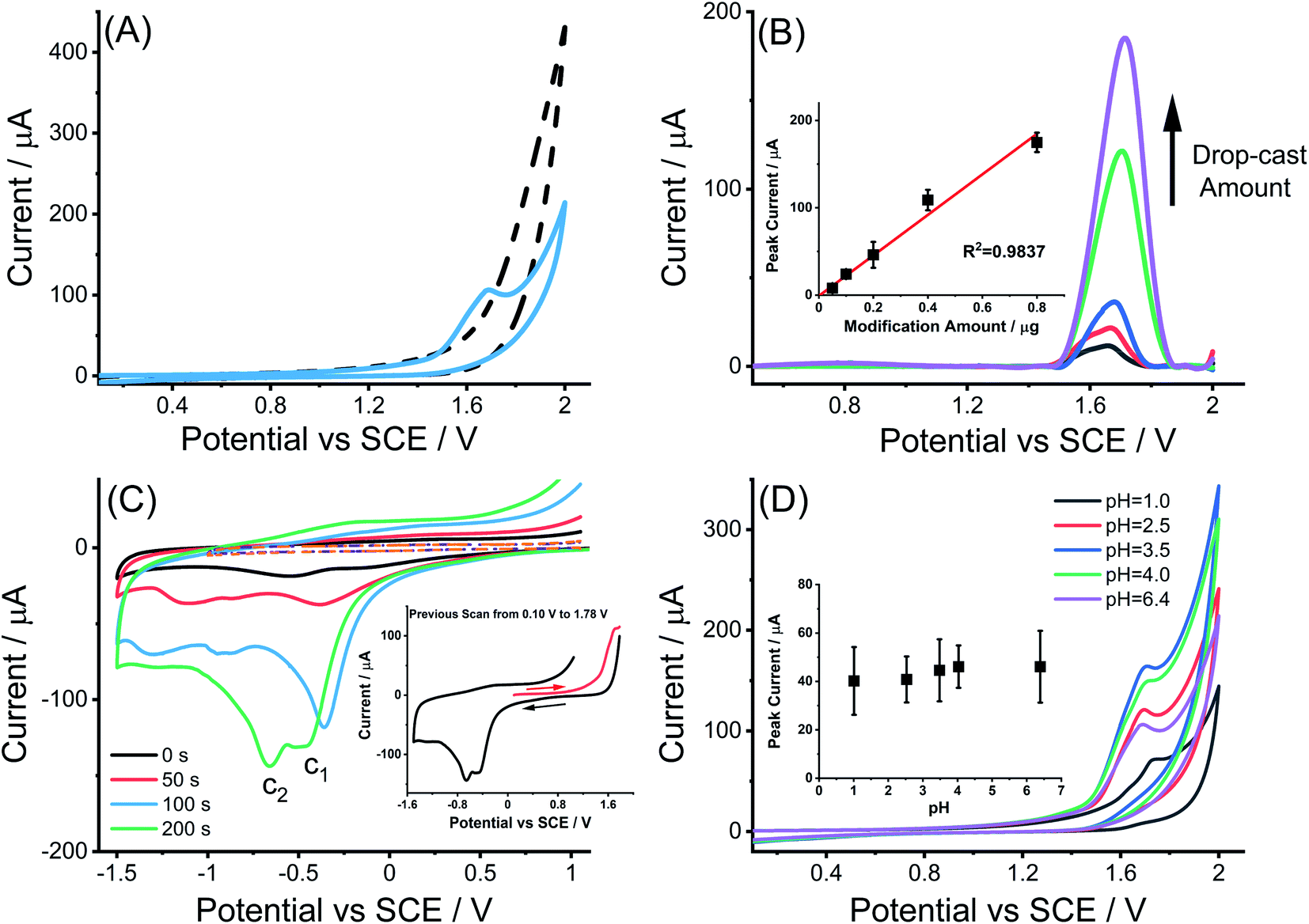 | ||
| Fig. 1 (A) Cyclic voltammograms of a bare GC electrode (black dashed curve) and a MWCNTs modified GCE (blue solid curve) immersed in 0.1 M KNO3 solution (pH = 6.4) by sweeping the potential from 0.1 V to 2.0 V vs. SCE; (B) voltammograms of MWCNTs modified GCEs with different modification amount of 0.05, 0.1, 0.2, 0.4 and 0.8 μg MWCNTs following background correction to the original cyclic voltammogram scanned in 0.1 M KNO3 (pH = 6.4) (inlay: plot of oxidative peak current versus MWCNTs modification amount on the polished GCE); (C) cyclic voltammograms of MWCNTs modified GCE recorded with a sweep from +1.0 V to −1.5 V after previous scan from 0.10 V to 1.78 V interrupted at a potential of 1.78 V for different durations of 0 s–200 s in 0.1 M KNO3 (pH = 6.4) (inlay: the cyclic voltammograms scanned across the full range from 1.78 V to −1.50 V when the duration of the fixed potential oxidation was 200 s) (D) Cyclic voltammograms of a MWCNTs modified GCE immersed in 0.1 M HNO3 (pH = 1.0) and 0.1 M KNO3 solutions at different pH values of 2.5, 3.5, 4.0 and 6.4 (inlay: pH variable study of oxidative peak current obtained from MWCNTs modified GCEs using CV after background subtraction as described in Experimental section). All voltammograms were conducted at a scan rate of 50 mV s−1. | ||
The pH variation of the oxidative peak at MWCNTs modified GCEs was studied by recording CVs in the pH range 1.0 to 6.4 (Fig. 1(D)) as described in the Experimental section. The potential of the oxidative peak was pH independent with an average value of 1.71 ± 0.03 V. The peak current data obtained in MWCNTs modified GCEs after background subtraction were plotted against the corresponding solution pH value (inlay of Fig. 1(D)) again indicating independence of the electro-oxidation of MWCNTs on pH in the range studied. This suggests that the rate limiting step for the oxidation of the CNTs leading to the introduction of oxygen functionality is slow electron transfer prior to any proton release.
Electro-oxidation of MWCNTs: nano-impact experiments
Nano impact experiments were conducted to probe the electro-oxidation of MWCNTs via the collision of individual MWCNTs particles with a microelectrode held at different potentials. A freshly polished carbon micro-disc electrode (diameter 33 μm) was first inserted into a suspension of 0.01 g L−1 MWCNTs supported by 0.1 M KNO3 with a pH of 6.4, as described in the experimental section and separately for comparison into a blank solution without particles. As seen in Fig. 2(A), at an applied potential of 1.90 V vs. SCE, clear current steps and spikes were seen in the presence of MWCNTs (black line) whereas no spikes or steps were observed in the absence of MWCNTs (red line). The average spike height (current) at 1.90 V was calculated to be 0.64 ± 0.06 nA and the average step height (current) at 1.90 V were measured as 0.25 ± 0.04 nA. Based on the frequency of spikes and steps in each chronoamperogram curve, the appearance ratio of spikes to steps is calculated to be 1.8 ± 0.7.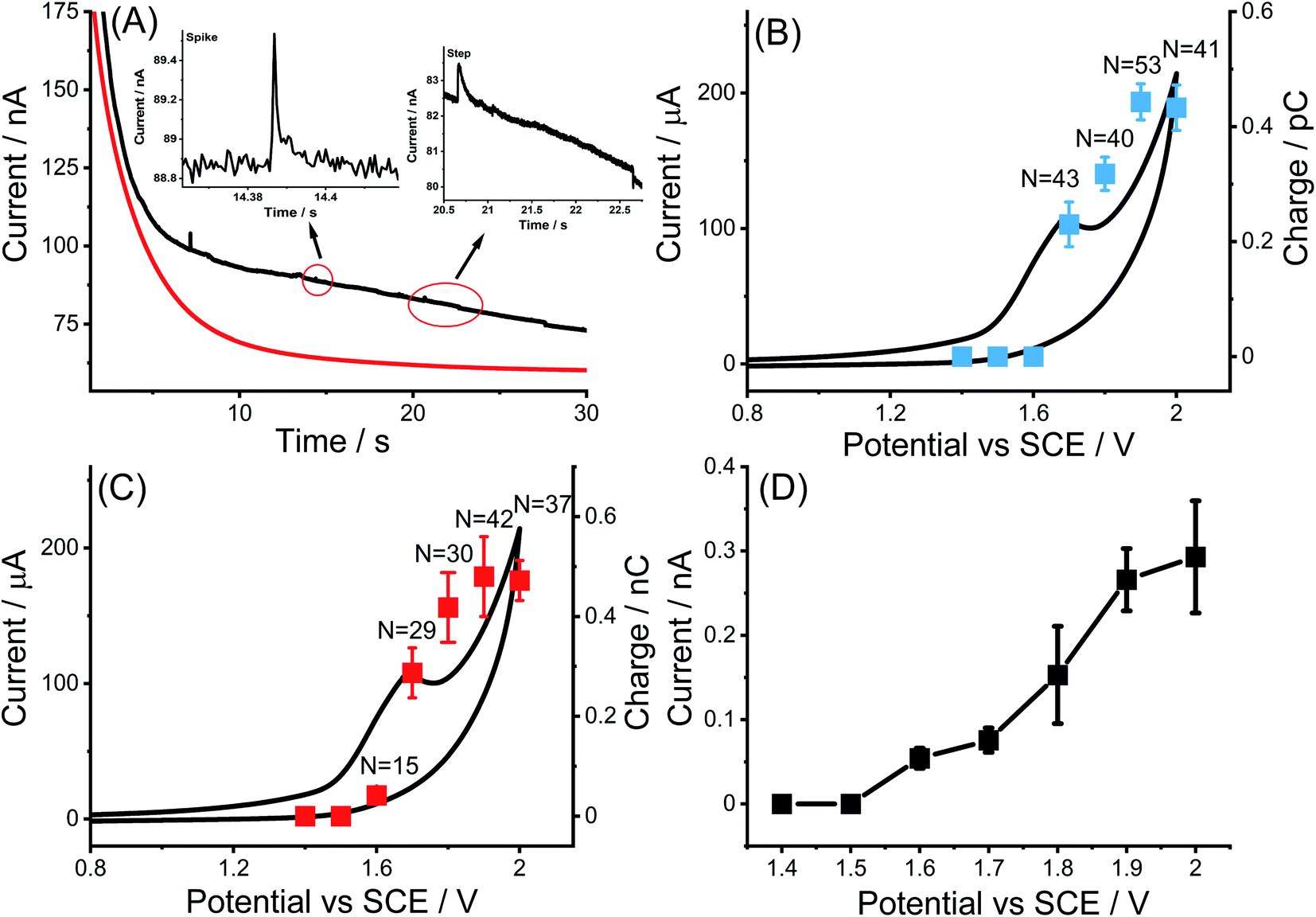 | ||
| Fig. 2 (A) Chronoamperograms of a carbon micro-disc electrode (d = 33 μm) immersed in a 0.1 M KNO3 (pH = 6.4) solution containing 0.01 g L−1 MWCNTs (black line) or not (red line) at a potential of 1.90 V vs. SCE. The inset is an enlarged view of impact spike and step at 1.90 V; overlay of the plot of average impact spike charge (B) and step charge (C) as a function of applied potentials with the cyclic voltammogram (black line) of MWCNTs modified GCE; (D) average step currents observed as a function of applied potential in 0.1 M KNO3 (pH = 6.4) containing 0.01 g L−1 MWCNTs (the error bars are derived from SD/(n)1/2, where SD is the standard deviation and n is the number of the spikes or steps). | ||
Further, impacts for the electro-oxidation of MWCNTs were observed at various potentials from 1.4 V to 2.0 V vs. SCE in the same solution. It was found that clear current spikes were observed in the chronoamperograms upon particle collisions with the electrode held at oxidizing potentials (1.7–2.0 V) and the current steps were observed in the chronoamperograms upon particle collisions with the electrode held at oxidizing potentials (1.6–2.0 V) (Fig. 3(A)–(D)). The rise times of the steps at high potentials may in part be controlled by the charging of the double layer associated with the CNTs. At and below 1.50 V, no impact signals were detected (see Fig. S2†). It is speculated that the steps are primarily associated with CNT catalysis of the solvent decomposition leading to the sustained currents seen for the impact duration. On the basis of the cyclic voltammetry reported above these will also be associated, to a smaller extent, by the oxidation of the nanotubes themselves forming surface functionality such as quinones. These may further enhance the catalysis of the solvent decomposition41 corresponding to the oxidation of water to oxygen. The mean impact frequencies and duration of impact signals as a function of potential are plotted in Fig. S3(A) and S3(B)† respectively, the frequency of spikes and steps were found to only slightly increase while each average duration stayed nearly the same from which over the potential range of 1.7 to 2.0 V. The step features require a sustained electrical contact between the tube and the electrode of average duration 4.6 ± 0.9 s (43 measurements). In contrast the spike features require a much shorter contact time (of average length 12 ± 1 ms from 53 measurements) and may reflect simply the end of a tube contacting the electrode. In this case, given the known greater susceptibility of tube ends to electrochemical reaction,42,43 these may be associated with the oxidation of the CNTs to oxygenated functionality. Fig. 4 shows a schematic view of the possible different collisions associated with the spikes and steps.
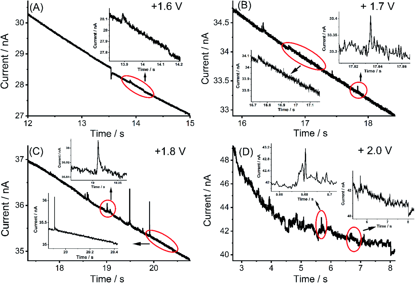 | ||
| Fig. 3 (A)–(D) Examples of representative chronoamperometric profiles of nano-impact at different potentials (1.60, 1.70, 1.80 and 2.00) in a 0.1 M KNO3 (pH = 6.4) solution containing 0.01 g L−1 MWCNTs. No spikes or steps were detected below/at 1.50 V. | ||
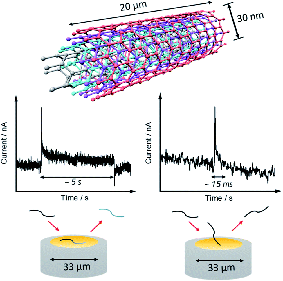 | ||
| Fig. 4 A schematic view of the possible different collisions of a single MWCNT on the micro-disc electrode (d = 33 μm) associated with the spikes and steps. | ||
The average charges of the individual spikes and steps from the collision of MWCNTs were measured as a function of the applied potential and the results are shown in Fig. 2(B) and (C) where the turn on of the electro-oxidation is seen to be consistent with cyclic voltammogram of MWCNTs modified GCEs in the same solution. A plateau of ca. 0.41 pC per spike was seen when the potential exceeded 1.90 V, but no spikes were observed at the potential more negative than 1.70 V, indicating that those spikes are a result of MWCNTs oxidation. The same condition occurred in the steps when the potential was more positive than 1.60 V, the average charge was seen to increase gradually and reached a constant level around ca. 0.50 nC but no steps were observed at the potential more negative than 1.60 V. The small difference in onset potentials might be speculated to indicate a different extent of the solvent oxidation as compared to oxidation of the CNT. The average impact step current plotted against the applied potential (Fig. 2(D)) indicated an upward trend over a potential range from 1.60 V consistent with the predominant process being water oxidation.
The insensitivity of the impacts (spikes and steps) to pH was demonstrated via an experiment carried out at a potential of 1.90 V in 0.1 M HNO3 (pH = 1.0) containing 0.01 g L−1 MWCNTs suspension. Concerning the spikes, these had an average charge of 0.40 ± 0.03 pC as measured from 48 current spikes consistent with the average charge from the oxidative spikes obtained in 0.1 M KNO3 at pH = 6.4 as reported above 0.43 ± 0.05 pC (the charge distribution is seen in Fig. S4(A) and S4(B)† respectively). The oxidative impact responses of MWCNTs particle have an average frequency of 0.053 ± 0.019 s−1, consistent with the 0.051 ± 0.012 s−1 frequency of the spikes observed in chronoamperograms in 0.01 g L−1 MWCNTs + 0.1 M KNO3 (pH = 6.4).
As for the steps appeared in 0.1 M HNO3 (pH = 1.0) in the presence of MWCNTs, an average charge of 0.47 ± 0.05 nC as measured from 52 current steps. Compared with the average charge from the oxidative steps obtained in 0.1 M KNO3 at pH = 6.4 (0.48 ± 0.07 nC) (the charge distribution is seen in Fig. 4(C) and S4(D)† respectively). The oxidative impact responses of MWCNTs particle have an average frequency of 0.044 ± 0.008 s−1, consistent with the 0.040 ± 0.007 s−1 frequency of the steps observed in chronoamperograms in 0.01 g L−1 MWCNTs + 0.1 M KNO3 (pH = 6.4). The result from the single electrochemistry of MWCNTs again indicates that the electro-oxidation reaction extent of pure MWCNTs is not controlled by solution pH.
The much larger charges resulting from the sustained currents seen in the steps are consistent with the assignment of these features to CNT catalyzed solvent decomposition. Moreover, the charges passed in the impact steps (0.48 ± 0.07 nC) are comparable in magnitude to those seen in the cyclic voltammetry when measured on a per nanotube basis (0.46 nC, see ESI Section 5† for details). This suggests that the peak seen in the cyclic voltammogram is not due to the formation of a finite number of oxygenated functionality, as also suggested by the relative size of the reductive CV features discussed above, but rather might be attributed to the porous nature of the CNT layer on the electrode surface (∼at least 13 layers, see ESI Section 6†) which can trap the protons released in the oxidation of the water leading to a local build-up of acidity. However, the above data indicates that the currents resulting from CNT catalysis of the solvent oxidation are insensitive to the value of the pH and hence the inhibition of the CNT catalyzed solvent decomposition resulting in a voltammetric peak may result from excessive electro-oxidation of the CNTs, consistent with the data in Fig. 1(C) showing not only progressively increasing oxygen functionality resulting from sustained electro-oxidation but also a change in the reductive voltammetric signal.
We next consider the origin of the spike currents where the charge is passed for ca. 12 ± 1 ms before terminating. These may reflect different types of CNT-electrode collision than occur during the step features. Since the latter persist with a steady current for tens of seconds, we suggest that the steps require electrical contact between the micro-disc electrode and CNT via the sides of the tubes, see Fig. 4. The spikes may reflect electrical contacts between the tube ends and the electrodes with the short, finite duration controlled either by the nature of the collision or, possibly, by the formation of insulating functionality via oxidation of the tube ends. The latter possibility is discounted by the calculation (see ESI Section 7†) that the average charge per spike results in rather more functional groups than could be accommodated at the end of a nanotube.
Cyclic voltammetry (CV) of MWCNTs-NH2
Next the electrochemical behavior of MWCNTs-NH2 was explored by applying cyclic voltammetry first in 0.1 M KNO3 (pH = 6.4) at a scan rate of 50 mV s−1. The potential range was chosen to be from 0.1 V to 2.0 V as shown in Fig. 5(A). In comparison with the MWCNTs modified GCE, a larger oxidative peak appeared with a peak potential of ca. 1.72 V vs. SCE under similar modification conditions. A good linear relationship between the height of the peak current and the amount of MWCNTs-NH2 drop-cast was observed as shown in Fig. 5(B).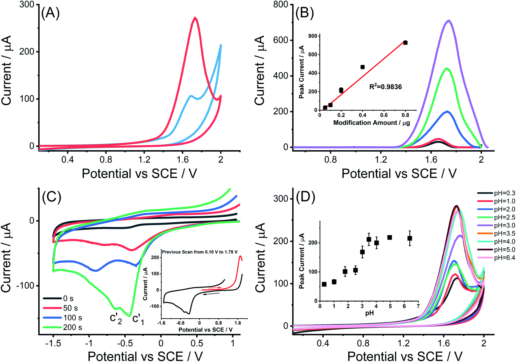 | ||
| Fig. 5 (A) Cyclic voltammograms of MWCNTs modified GCE (blue curve) and MWCNTs-NH2 modified GCE (red curve) immersed in 0.1 M KNO3 solution (pH = 6.4); (B) voltammograms of MWCNTs-NH2 modified GCEs with different modification amount of 0.05, 0.1, 0.2, 0.4 and 0.8 μg MWCNTs-NH2 following background correction to the original cyclic voltammogram scanned in 0.1 M KNO3 (pH = 6.4) (inlay: plot of oxidative peak current versus MWCNTs-NH2 modification amount on the polished GCE); (C) cyclic voltammograms of MWCNTs-NH2 modified GCE recorded at +1.0 V to −1.5 V after previous scan from 0.10 V to 1.78 V with a hold at a potential of 1.78 V for different duration of 0 s–200 s in 0.1 M KNO3 (pH = 6.4) (inlay: the cyclic voltammograms scanned across the full range from 1.78 V to −1.50 V when the held time was 200 s); (D) cyclic voltammograms of MWCNTs-NH2 modified GCE immersed in 1.0 M HNO3 (pH = 0.3), 0.1 M HNO3 (pH = 1.0) and 0.1 M KNO3 solutions at different pH of 2.0, 2.5, 3.0, 3.5, 4.0, 5.0 and 6.4. All the voltammetry were conducted by using sweep potential from 0.10 V to 2.0 V vs. SCE at a scan rate of 50 mV s−1 (inlay: pH variable study of oxidative peak current obtained from MWCNTs-NH2 modified GCE using CV). | ||
Analogous experiments to those conducted for MWCNTs were made to investigate the reductive voltammetric behavior following electro-oxidation of the MWCNTs-NH2 at 1.78 V, focusing on the potential range from +1.0 V to −1.5 V. As seen in Fig. 5(C), two cathodic peaks appeared at −0.40 ± 0.05 V (c′1) and −0.78 ± 0.14 V (c′2) similar to what was seen in the cyclic voltametric behavior of MWCNTs again suggesting that a small amount of the oxidative current is used to introduce oxygen containing functionality but that most of the current is CNT catalyzed solvent oxidation.
Cyclic voltammograms were recorded at different scan rates in the range of 25–400 mV s−1 in 0.1 M HNO3 (pH = 1.0) and 0.1 M KNO3 (pH = 6.4). Polynomial fitting curves were used to infer the charge passed on a MWCNTs-NH2 modified GCE as a function of scan rate (Fig. S6†). Extrapolation of the reciprocal charge against scan rate to zero scan rate gave the average charge of 6.0 mC in 0.1 M HNO3 (pH = 1.0), which is approximately consistent with the charge passed at a MWCNTs modified GCE (7.0 mC) representing a similar extent of solvent oxidation and functional group formation in both types of CNT since the mass drop cast was the same in both cases and the individual tubes have similar surface areas (see Table 1). However, a clear difference was noticed for the average charge passed on a MWCNTs-NH2 modified GCE in 0.1 M KNO3 (pH = 6.4) which was markedly larger than that at pH 1 and calculated to be 9.5 mC, suggesting that the presence or not of deprotonated –NH2 groups is greatly possible factor whereby the amine groups are deprotonated at high pH but protonated at pH 1 such that they are easily electro-oxidized at the higher pH but not at the lower pH.
| MWCNTs | MWCNTs-NH2 | |
|---|---|---|
| Diameter | 30 nm | 15 nm |
| Length | 20 μm | 50 μm |
| External surface area | 1.9 × 10⁻¹² m2 | 2.3 × 10⁻¹² m2 |
To explore this possibility, the variation of the magnitude of the oxidative peak as a function of solution pH was measured in the range from 0.3 to 6.4. Fig. 5(D) shows an overlay of cyclic voltammograms for the oxidation of MWCNTs-NH2 modified GCEs in various electrolytes: (a) 1.0 M HNO3, (b) 0.1 M HNO3 and (c) 0.1 M KNO3 of different pH as controlled by small additions of 0.1 M HNO3 or 0.5 M KOH assuming no ion pairing between nitrate and amino-groups on the CNTs.44–46 In this way the pH ranges from 0.3 to 6.4 was studied. The potential of the irreversible oxidative peak was unchanged with variation in pH with an average value of 1.73 ± 0.03 V. However, the plot of oxidative peak currents against pH value (inlay of Fig. 5(D)) shows an obvious pH-dependence in contrast to the MWCNTs modified GCEs. Specifically, the peak current was essentially pH independent between pH values of 0.3 to 2.5, then between pH 2.5 and 3.5, the height of oxidative peak current rose sharply as the pH was increased. Finally at pH above 4.0, the oxidative peak current remained stable. Overall a characteristic sigmoid-like ‘titration curve’ curve was seen. The magnitude of the current seen in the lowest pH range is of the same order of magnitude to that recorded for unmodified MWCNTs (albeit of different radius and length to the MWCNTs), suggesting that the same electrocatalytic solvent oxidation reaction as noted above for MWCNTs is also seen in MWCNTs-NH2 and occurs at essentially the same potential in both types of CNT. It is inferred that the oxidation potential of the unprotonated –NH2 groups approximately coincides with that of the electro-oxidation of the solvent. It is worthwhile to mention that the rate limiting step for the solvent oxidation and amino groups on the MWCNTs are inferred in each case to be the electron transfer prior to any proton release as reflected in the independence of the corresponding oxidation potentials on pH.
The additional current observed at higher pH is attributed to the oxidation of unprotonated –NH2 groups where further follow up chemistry is probable, on the basis of electro-oxidation mechanism of aromatic amines proposed by Weinberg,47 considering that aromatic amines usually have analogous hexatomic ring structure as is present in CNTs and generically show a single oxidative peak at a potential above 1.0 V vs. SCE when oxidized at a carbon working electrode under acidic conditions.48,49 This possible mechanism also provides a reasonable explanation for the formation of the sigmoid-like ‘titration’ curve of oxidative peak height versus pH value. However, it is noted that the oxidation of the –NH2 groups results in the release and build-up of protons so changing the local pH and extent of solvent oxidation. This precludes quantitative analysis of the CVs by subtraction of the ‘blank’ responses. Owing to the acid–base characteristics of the –NH2/–NH3+ pair, the electro-oxidation extent of electro-active –NH2 decreases when the solution became more acidic as the generation of the protonated species.
Single particle electrochemistry of MWCNTs-NH2
Analogous nano-impacts experiments of MWCNTs-NH2 to those made for MWCNTs were conducted in 0.1 M KNO3 (pH = 6.4) containing 0.01 g L−1 MWCNTs-NH2 at a freshly polished carbon micro-disc electrode. At a fixed potential of 1.90 V vs. SCE, clear impact signals (steps and spikes) as with MWCNTs were observed (Fig. 6).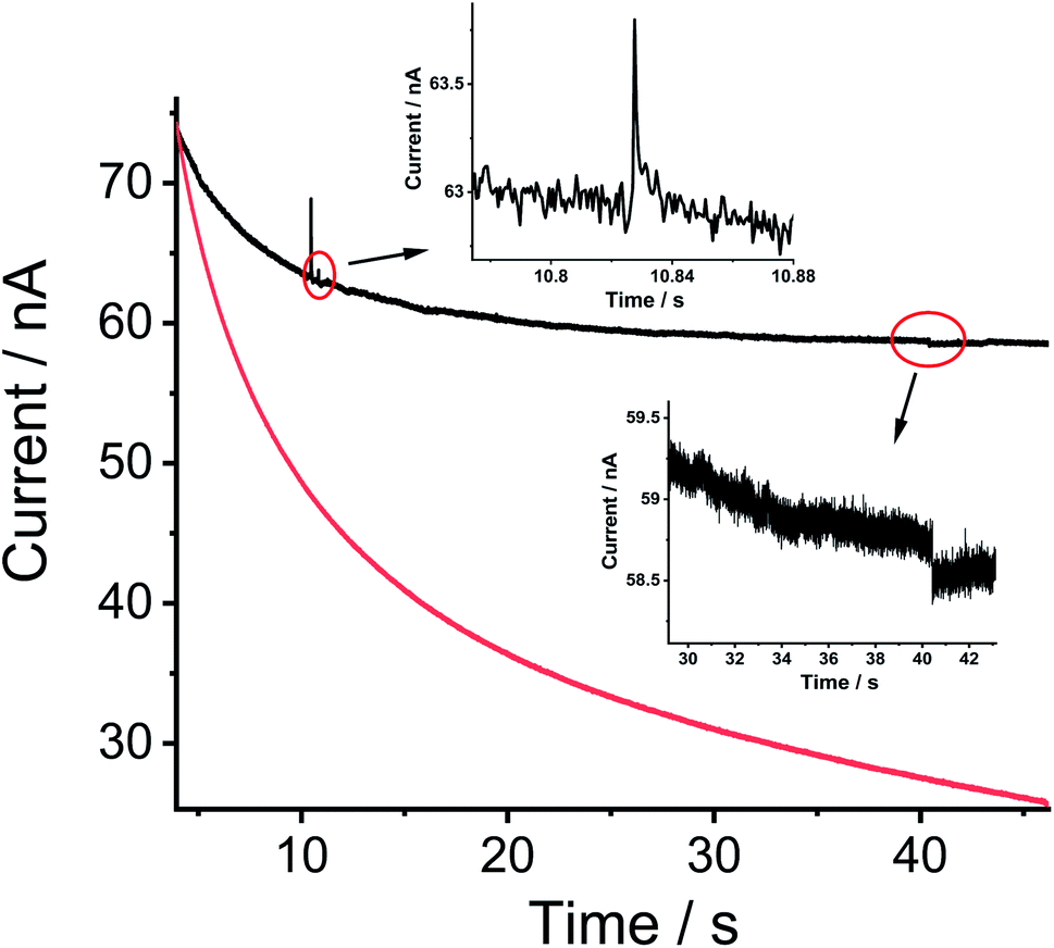 | ||
| Fig. 6 Chronoamperograms of a carbon micro-disc electrode (d = 33 μm) immersed in a 0.1 M KNO3 (pH = 6.4) solution containing MWCNTs-NH2 (black line) or not (red line) at a potential of 1.90 V vs. SCE. The inset is an enlarged view of impact spike and step at 1.90 V in the presence of MWCNTs-NH2. | ||
Analysis of the step data showed that in terms of average current, duration and frequency, it was essentially indistinguishable from that recorded for MWCNTs using solutions of varying pH from 0.3 to 6.4 (representative chronoamperograms are shown in Fig. S7(A)–(E)†). The average step current seen only in the presence of MWCNTs-NH2 fluctuated at 0.26 ± 0.06 nA which is close to the value (0.27 ± 0.04 nA) obtained from 0.1 M KNO3 (pH = 6.4) containing MWCNTs and was pH independent (Fig. S7(F)†). The corresponding oxidative step frequency under different pH condition (Fig. S8(A)†) stay nearly constant with a mean value of 0.039 ± 0.005 s−1, close to the frequency (0.037 ± 0.008 s−1) of the steps observed in 0.1 M KNO3 (pH = 6.4) containing 0.01 g L−1 MWCNTs (albeit of different radius and length). The step duration was found to be steady at 4.8 ± 1.0 s (Fig. S8(B)†) again consistent with what is seen in the presence of non-functionalized MWCNTs (4.7 ± 0.9 s).
The spike data however showed interesting contrasts with those seen for MWCNTs. The average charge from 89 spikes (the charge distribution is shown in Fig. S9†) for MWCNTs-NH2 at 1.90 V (0.62 ± 0.02 pC) was higher than the value (0.43 ± 0.05 pC) obtained from the collision of MWCNTs particle in 0.1 M KNO3 (pH = 6.4), suggesting the oxidation of unprotonated –NH2 groups bonded to MWCNTs.
To investigate the oxidative charge variation of MWCNTs-NH2 as a function of pH, current–time transients were recorded in solutions varying pH from 0.3 to 6.4 (Fig. 7(A)). The average charges of the individual spikes from the collision of MWCNTs-NH2 were measured as a function of the pH and the results (Fig. 7(B)) show two plateaus one at high (>3.7) and the other at low (<1.8) pH, which agree well with the variation of the oxidative peak current against pH variation observed in CV and again can be attributed to the different extents of amino group oxidation reflecting whether the amine groups are protonated or not. The corresponding oxidative spike frequency under different pH condition (Fig. S8(A)†) stay nearly the same with a mean value of 0.048 ± 0.010 s−1, close to the frequency (0.051 ± 0.012 s−1) of the spikes observed in 0.1 M KNO3 (pH = 6.4) containing 0.01 g L−1 MWCNTs (albeit of different radius and length but similar area). While the spike duration was found to be unchanged at 15 ± 2 ms (Fig. S8(B)†) that is only slightly higher than that in the presence of non-functionalized MWCNTs (12 ± 1 ms). All the results evidenced that transient electrocatalysis of solvent oxidation and oxidation of the deprotonated amino groups on the MWCNTs jointly contributed to the electro-oxidative spikes see for MWCNTs-NH2 but the latter resulted in a titration-like curve based on the experimental data from single and ensemble electrochemical behavior.
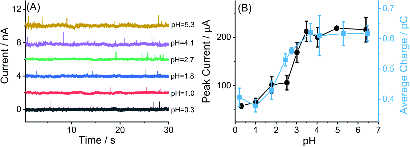 | ||
| Fig. 7 (A) Representative chronoamperograms of a carbon micro-disc electrode immersed in a 1.0 M (pH = 0.3) and 0.1 M HNO3 (pH = 1.0) and 0.1 M KNO3 solutions at different pH values of 1.8, 2.7, 4.1 and 5.3 containing 0.01 g L−1 MWCNTs-NH2 at a potential of 1.90 V vs. SCE; (B) the comparison of oxidative peak current from CV (black dots) and average charge from oxidative spikes (blue dots) as a function of solution pH. | ||
Determination of MWCNTs-NH2 pKa using cyclic voltammetry and nano impact data
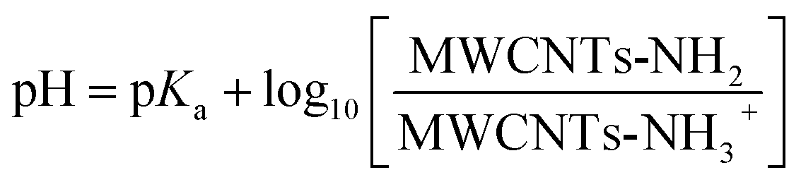
The average pKa of the amino groups in MWCNTs-NH2 is defined by the equilibrium between protonated and unprotonated amino groups functionalized on the surface of carbon nanotubes:MWCNTs-NH2 + H+ ![[left over right harpoons]](https://www.rsc.org/images/entities/char_21cb.gif) MWCNTs-NH3+ MWCNTs-NH3+ | (1) |
 | (2) |
In the following we estimate the pKa from both the CV and impact data. First from the CV we assume that the difference in the peak current seen in acid (–NH3+ only present) and in near neutral condition (–NH2 exclusively present) reflects the extent of the deprotonation inferred in solution of higher pH. Thus, the oxidative peak current (Ip) at a MWCNTs-NH2 modified GCE reflects two parts: the deprotonated [MWCNTs-NH2] and protonated [MWCNTs-NH3+], then Ip can be described as:
| Ip = INH2[MWCNTs-NH2] + INH3+[MWCNTs-NH3+] | (3) |
Assuming the sum [MWCNTs-NH2] + [MWCNTs-NH3+] is a constant, according to eqn (1)–(3), the following equation can be obtained (4):
 | (4) |
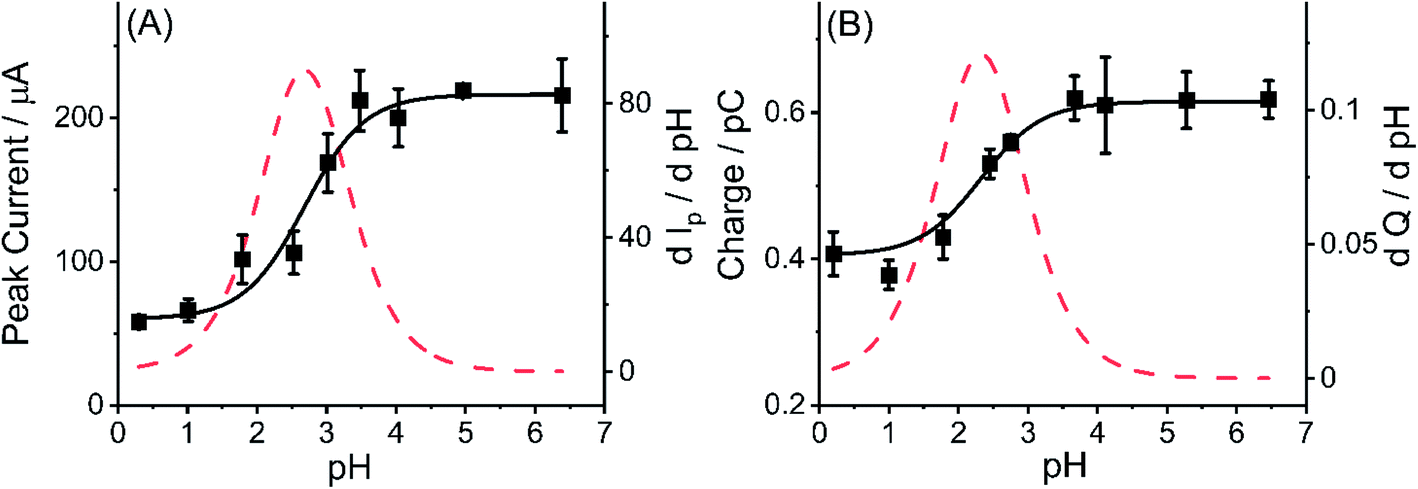 | ||
| Fig. 8 (A) Relationship between oxidative peak current of MWCNTs-NH2 modified GCE and pH value of solution; (B) relationship between average charge of oxidative spikes and pH value of solutions in the presence MWCNTs-NH2 (black square: experimental data; black solid line: simulated curve, and red dotted line: differential curve of experimental data). | ||
For comparison, the pKa of amino group in MWCNTs was also estimated using the experimental data from nano impact. Using the same assumptions as above, a non-linear curve was fitted (see ESI Section12†) to the average charge of oxidative spikes as a function of pH was plotted in Fig. 8(B) (R2 = 0.9656, black solid line). The differential curve (red dotted line) reflected the change of incremental ratio (dQ/dpH) and the highest inflection point was estimated to be 2.3 ± 0.1 as the pKa of amino groups on the MWCNTs, which is slightly smaller than that inferred using the CV method. The breadth of the transition from low to high pH in Fig. 8(A) and (B) are similar and may reflect the response of amino groups in different locations on the tube surface.
Conclusions
The electro-oxidation of MWCNTs and MWCNTs-NH2 have been studied by single and ensemble electrochemistry respectively within the range of pH values from 0.3 to 6.4. It opens up a new and generic approach to the study of the oxidation of entities made of carbon allotropes and of different forms of CNTs in particular. The MWCNTs-NH2 and the MWCNTs at all pHs studied show catalysis of the solvent (water) decomposition together with the introduction of new surface functionality. The case of MWCNTs-NH2 at higher pH shows excess oxidative charge in the case in impact spikes and peak current in the CV. The excess faradaic component is attributed to the electro-oxidation of the amino group when deprotonated, a process which is inhibited when they exist in the –NH3+ form. Based on the pH variation of oxidative peak current in MWCNTs-NH2 modified GCE and the oxidative spike average charge of one single MWCNTs-NH2 particle, the pKa values of –NH2 bonded to MWCNTs determined by two ways in our work are estimated to be around 2.5 at 298 K. This study will assist in controlling and rationalizing the chemical reactivity of the –NH2 groups bonded to carbonaceous material utilized as a catalyst or support composites.Experimental section
Chemicals and reagents
Amino multi-walled carbon nanotubes (MWCNTs-NH2, amino ratio: ∼0.45 wt%, outer diameter = 8–15 nm, inner diameter = 3–5 nm, length = 50 μm) were purchased from Nanjing XFNANO Materials Tech Co., Ltd (Nanjing, China). The MWCNTs-NH2 were synthesized via the following procedure of three steps: (i) the introduction of carboxylic acid groups at defects (tube ends, vacancies, etc.) in the MWCNTs made by chemical vapor deposition (CVD) to form MWCNTs-COOH; (ii) the reaction of the –COOH groups to form –CO–NH2 groups via chemical reaction with liquid ammonia;50 (iii) decarbonylation to remove the carbonyl group, so that the amino groups become directly linked with carbon atoms in the MWCNTs to obtain the final product MWCNTs-NH2, the structure is shown schematically in Fig. 9 with the NH2 group attached to an aromatic ring.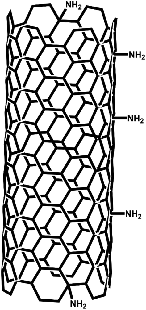 | ||
| Fig. 9 Schematic structure of the single layer of MWCNTs-NH2. | ||
Bamboo like multiwall carbon nanotubes (MWCNTs, BPD30L5-20, diameter = 30 ± 15 nm, length = 5–20 μm) were purchased from Nanolab (Brighton, MA, USA). The MWCNTs and MWCNTs-NH2 were used for comparative experiments as described below. Their dimensions are compared in Table 1 and it is noticed that the external surface area of the two different types of individual carbon nanotubes are similar (∼2 × 10⁻¹² m2) so permitting comparisons made below.
All chemicals were of analytical grade and were used as received without any further purification. Nitric acid (HNO3, 70%), potassium hydroxide (KOH, 85%), potassium nitrate (KNO3, 99.99%), ethanol (≥99.8% purity) were obtained from Sigma-Aldrich (Dorest, UK). 0.1 M KNO3 with different pH values (adjusted by additions of 0.1 M HNO3 or 0.5 M KOH) was used as a supporting electrolyte in all cyclic voltammetric and chronoamperometric measurements. All solutions were prepared in ultra-pure water at a resistivity of 18.2 MΩ cm at 298 K (Millipore, MA, USA) and were deaerated thoroughly with nitrogen (99.998%, BOC Gases plc) before use.
Cyclic voltammetry of MWCNTs and MWCNTs-NH2 modified GCEs
A suspension of 0.1 g L−1 MWCNTs-NH2 was prepared by adding 1.0 mg of MWCNTs-NH2 to 10 mL ethanol. The suspension was then sonicated for 30 min in a Fisher Scientific FB15050 ultrasonic bath to get a well-dispersed solution. The glassy carbon macro electrode (GCE, diameter = 3.02 ± 0.005 mm) was polished carefully using alumina with decreasing particle sizes of 1.0, 0.3 and 0.05 μm (Buehler, IL, UK) in turn on soft lapping pads (Buehler, UK), followed by rinsing with ultra-pure water and drying with nitrogen. The freshly polished GCE was modified by drop-casting a 2 μL (0.2 μg of MWCNTs-NH2) suspension of MWCNTs-NH2 and left to dry under vacuum. Cyclic voltammetry (CV) was carried out in a Faraday cage at 298 K using an EC-Lab potentiostat (SP-200 with ultra-low current module, Biologic Science Instruments, France). A conventional three-electrode system was operated with a MWCNTs-NH2 modified GCE as the working electrode, a saturated calomel electrode (SCE, ALS distributed by BASi Inc., Japan) used as the reference electrode and a graphite rod as the counter electrode. Based on the same procedure as above, MWCNTs modified GCEs were prepared again with 0.2 μg of MWCNTs via drop casting and studied voltammetrically in an analogous way to the MWCNTs-NH2 modified GCEs.To investigate the electrochemical oxidative peak current obtained by MWCNTs and MWCNTs-NH2 modified GCEs at variable pH, CVs were conducted by immersing a freshly prepared MWCNTs modified GCE or MWCNTs-NH2 modified GCE respectively in a 1.0 M HNO3 (pH = 0.3), 0.1 M HNO3 (pH = 1.0) and 0.1 M KNO3 solution at different pH values of 2.0, 2.5, 3.0, 3.5, 4.0, 5.0 and 6.4 by changing the addition amount of 0.1 M HNO3 or 0.1 M KOH under degassed conditions as above. The potential window was chosen as +0.1 V to +2.0 V vs. SCE. The voltammograms were recorded at a scan rate of 50 mV s−1. A control experiment was also performed in the same solution but on a bare GCE.
To determine the voltammetric signals from the oxidation of MWCNTs and MWCNTs-NH2 quantitively, the peak current was found using OriginPro 2020 after background correction of the raw cyclic voltammograms. This is illustrated in Fig. S10 (ESI Section 13†), where a baseline spline is fitted between the potentials at which the voltammetric wave is judged to have started and ended, then subtracted from the peak to obtain the actual peak height.
To investigate possible surface functional group formation on electro-oxidation voltammetry, CV was conducted using MWCNTs or MWCNTs-NH2 modified GCE in 0.1 M KNO3 (pH = 6.4) by first sweeping from +0.10 V to +1.78 V then applying a fixed potential of +1.78 V for 0 s, 50 s, 100 s and 200 s respectively. After that, the potential was swept from +1.78 V to −1.50 V and back to +1.0 V under degassed conditions as above. The voltammograms were recorded at a scan rate of 50 mV s−1.
Nano-impact experiments of MWCNTs and MWCNTs-NH2
Nano-impact experimental measurements were performed by chronoamperometry using an EC-Lab Biologic potentiostat where the charge passed during the impact events was conserved. A carbon micro-disc electrode of nominally 33 μm diameter (IJ Cambria Scientific Ltd, UK) was used as the working electrode. Before each experiment, it was polished as described above. Pure MWCNTs was separately dispersed into 0.1 M HNO3 (pH = 1.0) and 0.1 M KNO3 (pH = 6.4) to form a uniform suspension (0.1 mg/10 mL) after 30 minute sonication. Then the measurements of current at various potentials in the range from 1.4 V to 2.0 V vs. SCE (“chronoamperometry”) were performed on the 0.1 M KNO3 (pH = 6.4) solution containing dispersed MWCNTs after bubbling with nitrogen for 10 minutes. An atmosphere of nitrogen was maintained during the experiments. Control experiments were conducted in the presence of 0.01 g L−1 MWCNTs-NH2 suspension. The effect of pH condition on the chronoamperometric current spikes and steps produced was investigated by placing the freshly polished carbon micro-disc electrode into 1.0 M HNO3 (pH = 0.3), 0.1 M HNO3 (pH = 1.0) and 0.1 M KNO3 solution at different pH values of 0.3, 1.0, 1.8, 2.4, 2.7, 3.6, 4.1, 5.3 and 6.4 (adjusted by a small addition of 0.1 M HNO3 or 0.5 M KOH) containing 0.01 g L−1 MWCNTs-NH2 suspension or not. The data analysis program “Signal Counter” (Centre for Marine and Environmental Research, Zagreb, Croatia)51 was employed for making impact spike identification and individual spike charge determination. Counting and analysis of the impact step signals were performed in OriginPro 2020.Data availability
The datasets supporting this article have been uploaded as part of the ESI.†Author contributions
YL – performed experiments, investigation, data analysis, and writing – original draft. XL – writing – review and editing. RGC – conceptualization, resources, supervision, and writing – review and editing.Conflicts of interest
The authors declare no competing financial interest.References
- J. H. Lehman, M. Terrones, E. Mansfield, K. E. Hurst and V. Meunier, Carbon, 2011, 49, 2581–2602 CrossRef CAS.
- Y. Ando, X. Zhao, H. Shimoyama, G. Sakai and K. Kaneto, Int. J. Inorg. Mater., 1999, 1, 77–82 CrossRef CAS.
- A. Rawal and V. Kumar, Appl. Phys. Lett., 2013, 103, 153103 CrossRef.
- Y. Chen, C. Liu, F. Li and H.-M. Cheng, J. Porous Mater., 2006, 13, 141–146 CrossRef CAS.
- L. Fu, Y. Q. Liu, Z. M. Liu, B. X. Han, L. C. Cao, D. C. Wei, G. Yu and D. B. Zhu, Adv. Mater., 2006, 18, 181–185 CrossRef CAS.
- P. K. Brahman, L. Suresh, V. Lokesh and S. Nizamuddin, Anal. Chim. Acta, 2016, 917, 107–116 CrossRef CAS PubMed.
- S. M. Azab and A. M. Fekry, RSC Adv., 2017, 7, 1118–1126 RSC.
- C. Jia-jia, J. Xin, S. Qiu-jie, W. Chong, Z. Qian, Z. Ming-sen and D. Quan-feng, Electrochim. Acta, 2010, 55, 8062–8066 CrossRef.
- R. Shu, W. Li, Y. Wu, J. Zhang and G. Zhang, Chem. Eng. J., 2019, 362, 513–524 CrossRef CAS.
- Q. Shu, W. Zou, J. He, H. Lesmana, C. Zhang, L. Zou and Y. Wang, Renewable Energy, 2019, 135, 836–845 CrossRef CAS.
- N. Gupta, S. M. Gupta and S. K. Sharma, Carbon Lett., 2019, 29, 419–447 CrossRef.
- K. Balasubramanian and M. Burghard, Small, 2005, 1, 180–192 CrossRef CAS PubMed.
- Y. Liu, L. Gao, J. Sun and Y. Wang, J. Ceram. Process. Res., 2010, 11, 120–122 Search PubMed.
- T. I. T. Okpalugo, P. Papakonstantinou, H. Murphy, J. McLaughlin and N. M. D. Brown, Carbon, 2005, 43, 153–161 CrossRef CAS.
- J. Shen, W. Huang, L. Wu, Y. Hu and M. Ye, Mater. Sci. Eng., A, 2007, 464, 151–156 CrossRef.
- M. Soleimani, M. Ghahraman Afshar and A. Sedghi, ISRN Nanotechnol., 2013, 2013, 1–8 CrossRef.
- G. Yang, X. Chen, Q. Pan, W. Liu and F. Zhao, Int. J. Electrochem. Sci., 2017, 12, 7272–7286 CrossRef CAS.
- Y. Sugano, S. Kuittinen, O. Turunen and A. Pappinen, Bioinspiration Biomimetics, 2019, 14, 036007 CrossRef CAS PubMed.
- X. Ma, D. Deng, N. Xia, Y. Hao and L. Liu, J. Nanomater., 2021, 11, 1757 CrossRef CAS PubMed.
- S. Shahzad, L. Karadurmus, B. Dogan-Topal, T. Taskin-Tok, A. Shah and S. A. Ozkan, Electroanalysis, 2019, 32, 912–922 CrossRef.
- A. V. Velasco, J. R. Romo and H. E. Duran, J. Phys. Conf. Ser., 2019, 1159, 12003 CrossRef.
- M. Garrido, L. Gualandi, S. Di Noja, G. Filippini, S. Bosi and M. Prato, Chem. Commun., 2020, 56, 12698–12716 RSC.
- G. Vuković, A. Marinković, M. Obradović, V. Radmilović, M. Čolić, R. Aleksić and P. S. Uskoković, Appl. Surf. Sci., 2009, 255, 8067–8075 CrossRef.
- G. Papp, G. Olveti, H. Horvath, A. Katho and F. Joo, Dalton Trans., 2016, 45, 14516–14519 RSC.
- H. Gong, S.-T. Kim, J. D. Lee and S. Yim, Appl. Surf. Sci., 2013, 266, 219–224 CrossRef CAS.
- Z. Zhang, L. Pfefferle and G. L. Haller, Catal. Today, 2015, 249, 23–29 CrossRef CAS.
- P. Abiman, A. Crossley, G. G. Wildgoose, J. H. Jones and R. G. Compton, Langmuir, 2007, 23, 7847–7852 CrossRef CAS PubMed.
- W. N. Olmstead, Z. Margolin and F. G. Bordwell, J. Org. Chem., 1980, 45, 3295–3299 CrossRef CAS.
- Y. Zeng, X. Chen, D. Zhao, H. Li, Y. Zhang and X. Xiao, Fluid Phase Equilib., 2012, 313, 148–155 CrossRef.
- M. D. Liptak, K. C. Gross, P. G. Seybold, S. Feldgus and G. C. Shields, J. Am. Chem. Soc., 2002, 124, 6421–6427 CrossRef CAS PubMed.
- P. Abiman, G. G. Wildgoose, A. Crossley, J. H. Jones and R. G. Compton, Chemistry, 2007, 13, 9663–9667 CrossRef CAS PubMed.
- R. Barhdadi, M. Troupel, C. Comminges, M. Laurent and A. Doherty, J. Phys. Chem. B, 2012, 116, 277–282 CrossRef CAS PubMed.
- N. V. Rees, Electrochem. Commun., 2014, 43, 83–86 CrossRef CAS.
- W. Cheng and R. G. Compton, TrAC, Trends Anal. Chem., 2014, 58, 79–89 CrossRef CAS.
- P. H. Robbs and N. V. Rees, Phys. Chem. Chem. Phys., 2016, 18, 24812–24819 RSC.
- J. Ye, X. Liu, H. F. Cui, W. Zhang, F. Sheu and T. M. Lim, Electrochem. Commun., 2005, 7, 249–255 CrossRef CAS.
- A. Doepke, C. Han, T. Back, W. Cho, D. D. Dionysiou, V. Shanov, H. B. Halsall and W. R. Heineman, Electroanalysis, 2012, 24, 1501–1508 CrossRef CAS.
- T. L. d. A. Montanheiro, F. H. Cristóvan, J. P. B. Machado, D. B. Tada, N. Durán and A. P. Lemes, J. Mater. Res., 2014, 30, 55–65 CrossRef.
- R. Sadri, M. Hosseini, S. N. Kazi, S. Bagheri, N. Zubir, K. H. Solangi, T. Zaharinie and A. Badarudin, J. Colloid Interface Sci., 2017, 504, 115–123 CrossRef CAS PubMed.
- B. R. Eggins and J. Q. Chambers, J. Electrochem. Soc., 1970, 117, 186 CrossRef CAS.
- C. A. Little, R. Xie, C. Batchelor-McAuley, E. Katelhon, X. Li, N. P. Young and R. G. Compton, Phys. Chem. Chem. Phys., 2018, 20, 13537–13546 RSC.
- M. Pumera, Chem.–Eur. J., 2009, 15, 4970–4978 CrossRef CAS PubMed.
- C. E. Banks, T. J. Davies, G. G. Wildgoose and R. G. Compton, Chem. Commun., 2005, 829–841 RSC.
- L. Pederson and S. Bryan, Assessment of the potential for ammonium nitrate formation and reaction in Tank 241-SY-101, Pacific Northwest Lab., Richland, WA (United States), 1994 Search PubMed.
- J. Glazer, E. Hughes, C. Ingold, A. James, G. Jones and E. Roberts, J. Chem. Soc., 1950, 2657–2678 RSC.
- J. B. Tingle and F. Blanck, J. Am. Chem. Soc., 1908, 30, 1395–1412 CrossRef CAS.
- N. Weinberg and H. J. C. R. Weinberg, Chem. Pharm. Bull., 1968, 68, 449–523 CAS.
- L. Sharma, A. Manchanda, G. Singh and R. S. Verma, Electrochim. Acta, 1982, 27, 223–233 CrossRef CAS.
- M. Masui and S. Ozaki, J. Chem. Pharm. Bull., 1978, 26, 2153–2159 CrossRef CAS.
- R. M. Lanigan and T. D. Sheppard, Eur. J. Org. Chem., 2013, 2013, 7453–7465 CrossRef CAS.
- J. Ellison, K. Tschulik, E. J. Stuart, K. Jurkschat, D. Omanovic, M. Uhlemann, A. Crossley and R. G. Compton, ChemistryOpen, 2013, 2, 69–75 CrossRef CAS PubMed.
Footnote |
| † Electronic supplementary information (ESI) available: Fourier-transform infrared spectroscopy (FTIR) characterization of MWCNTs, chronoamperograms of a carbon micro-disc electrode at lower potentials, potential variation of impact frequency and the average spike duration time in the presence of MWCNTs, the charge distribution of spikes in the presence of MWCNTs, the average functional group coverage on a single MWCNT based on ensemble electrochemistry, estimation of the number of layers of MWCNTs drop-casted on the GC electrodes, estimation of the number of functional groups possibly created by electro-oxidation on a single MWCNT, the calculation of the average charge passed at a MWCNTs-NH2 modified GCE, representative chronoamperograms showing impacts of MWCNTs-NH2, pH variation of impact frequency and average duration time of spikes and steps in impacts of MWCNTs-NH2, the charge distribution of spikes from impacts of MWCNTs-NH2, the non-linear fitting of the relationship between average charge of oxidative spikes and pH value and background subtraction of original cyclic voltammograms (PDF). See DOI: 10.1039/d1sc06122d |
| This journal is © The Royal Society of Chemistry 2022 |