 Open Access Article
Creative Commons Attribution 3.0 Unported Licence
Steps, hops and turns: examining the effects of channel shapes on mass transfer in continuous electrochemical reactors†
Hamish R.
Stephen
 a,
Sarah
Boyall
 a,
Christiane
Schotten
a,
Richard A.
Bourne
a,
Christiane
Schotten
a,
Richard A.
Bourne
 b,
Nikil
Kapur
 *c and
Charlotte E.
Willans
 *a
*a
aSchool of Chemistry, University of Leeds, Leeds, LS2 9JT, UK. E-mail: C.E.Willans@leeds.ac.uk
bSchool of Chemical and Process Engineering, University of Leeds, Leeds LS2 9JT, UK
cSchool of Mechanical Engineering, University of Leeds, Leeds LS2 9JT, UK. E-mail: N.Kapur@leeds.ac.uk
First published on 6th January 2022
Abstract
Due to the heterogenous nature of electrochemical reactions, mass transport is an important consideration during reaction and reactor development. The effect of different flow channel geometries on mass transfer between wall and solution within a continuous electrochemical reactor has been investigated using experimental studies and computational fluid dynamics. The channel shape is shown to have modest impact on the mass transfer coefficient. However, the reaction solution hopping from one side of an electrode to the other, so switching polarity mid-flow, has the greatest effect.
Electrochemistry offers an atom efficient method of conducting redox reactions in a selective and mild way. Furthermore, the scope and potential of this methodology has increased considerably over the past two decades.1–4 Recently, numerous groups have investigated the scaling up of electrochemical reactions by developing continuous flow protocols.5–8 Conducting electrochemistry in flow has a number of benefits; the electrode surface area to volume ratio is larger and the interelectrode distance can be smaller, reducing the amount of electrolyte and in some cases dispensing with the need for it entirely, as well as lowering the overpotential required for a reaction. In addition, throughput may be increased.7,9,10 With user-friendly and affordable equipment becoming more readily available, the field of synthetic electrochemistry has undergone a renaissance.1,11
Being heterogeneous in nature, mass transfer between surface and solution is of considerable importance to electrochemical reactions; reaction rates can be limited by mass transfer and in some cases mass transfer can affect the selectivity of a reaction.12 When designing new reactors the effects of mass transfer and inefficient mixing are often overlooked. Most work on mass transfer in continuous electrochemical reactors has focused on inserting obstructions into the flow channels, such as meshes and beads, to act as turbulence promotors13–19 (perhaps more accurately termed mixing promotors). These are ideal for plate and frame modules as they are easy to implement, including on large scales often with turbulent flows, though controlling the mass transfer by simply changing the shape of flow channels would be a more ideal solution for extended channel flow cells.
Laminar flow normally dominates in microreactors, with turns providing a potential source of mixing.5,10,20–22 Brown, Pletcher and co-workers have used this idea to explain the design of flow channel shapes within their reactors,17–19 however only one study has directly compared different flow channel designs.23 Cantillo and co-workers demonstrated that the efficiency of a decarboxylative methylation reaction could be improved by using flow channels with meandering paths or tangential mixers, when compared to a flow channel with fewer turns (Fig. 1).23
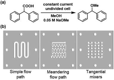 | ||
| Fig. 1 a) Decarboxylative methylation of diphenylacetic acid as a model reaction. b) Flow paths examined, with a meandering channel or tangential mixers lead to an increased yield. Reproduced from ref. 23 with permission from Wiley. | ||
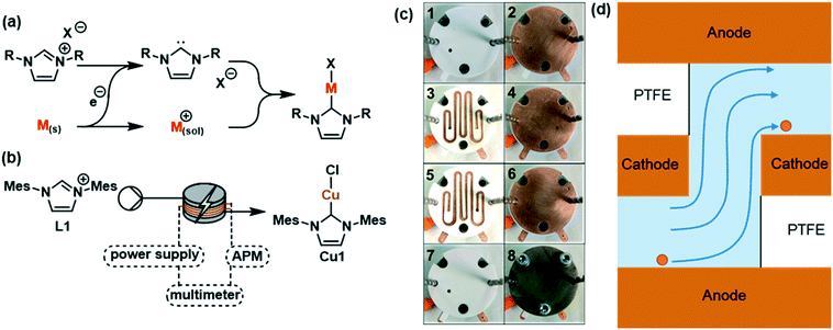
Our group has developed the continuous electrochemical synthesis of organometallic complexes (Fig. 2a).24 We have previously demonstrated that the geometries of a flow channel can affect the selectivity of these reactions. The first reactor comprised a linear flow channel in which we experienced selectivity issues due to insufficient mixing. This was addressed by inserting glass beads in a staggered formation which acted as turbulence promoters. In an effort to improve the design, we developed a second reactor featuring stacked electrodes that alternate between cathode and anode, separated by PTFE spacers with the flow channel cut into them. This second reactor allowed almost full conversion to Cu1 (Fig. 2b) in a single pass and with no selectivity issues. A miniaturised version was built to allow smaller quantities of catalyst to be produced for high-throughput screening (Fig. 2c) and has been used in the electrochemical synthesis of [Cu(MeCN)4]OTf,25 in addition to being used to examine the effect of alternating polarity.26
In this study, five different geometries of the flow channel were cut into the PTFE spacers for the miniaturised reactor (Fig. 3, A–E). All spacers had a thickness of 1 mm with the width of the channel and the number of turns being varied. The number of spacers was adjusted to achieve comparable volumes within the overall reactor. Where multiple spacers are used, the reaction mixture has to pass through an electrode to reach the next spacer, in what will be referred to as a hop (Fig. 2d). Fig. 3E shows a high hop count spacer with fluid cycling between electrode pairs 20 times. This was designed as a result of data from spacers A–D, with six spacers (three pairs) and seven electrodes used to give a comparable channel volume.
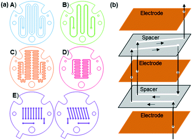 | ||
| Fig. 3 a) The five different spacers used in the third-generation reactor. b) Schematic showing how the pairs of spacers in E connect via hops. Only 4 channels are shown for clarity. | ||
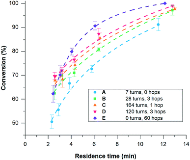
The synthesis of Cu1 from L1 and copper electrodes (Fig. 2b) was used as a model reaction to examine the different spacers. During the reaction L1 is reduced at the cathode generating a carbene, which is able to combine with metal ions produced at the sacrificial anode to form the product (Fig. 2a). A solution of L1 (6 mM in anhydrous acetonitrile) was pumped through the reactor at a range of flow rates (laminar flow) whilst a low frequency (1/60 Hz) alternating potential of 1.8 V was applied to give stable reaction conditions.211H NMR spectroscopy was used to calculate the conversion using the integrals of L1 and Cu1 (Fig. 4). Spacers A–D were tested initially, with longer residence times resulting in a higher conversion to the product as expected. Spacer A, with the fewest number of turns, gave the lowest conversion across the range of residence times, which increased upon increasing the number of turns (B–D). However, spacers C and D gave similar conversions to each other, with C having 164 turns compared to only 120 turns in D. Aside from the number of turns, the main difference between C and D is the number of spacers required; two C spacers are used whilst four D spacers are required to give comparable volumes. Hence, although D has fewer turns, the reaction solution passes through the electrodes more times i.e. 3 hops for D compared to 1 hop for C. This would suggest that passing through an electrode in a hop has a larger effect on the conversion in comparison to a turn, resulting in the development of spacer E to test this hypothesis.
Using spacer E, conversion to Cu1 at different residence times differs significantly compared to the other spacers (Fig. 4). At longer residence times (>4 minutes), the reactor with spacer E gave the highest conversion. However, at shorter residence times (<4 minutes) the conversion is comparable to the other spacers. This may be a result of the time scale of the reaction. If the polarity of the electrode is alternated more quickly than the reaction can take place then a drop in conversion would be expected, as was observed in a previous study when the polarity was alternated at high frequencies using A.26 The use of spacer E, which effectively alternates electrodes as the solution passes through a hop, at fast flow rates (shorter residence time) may simulate a fast alternating polarity.
An increased conversion with a larger number of hops could be due to an increase in the mass transfer coefficient due to the effective, constant renewal of reactants near the electrodes. The hop acts to replenish material into the area where a reaction is taking place. In laminar flow conditions, limited mixing across the channel diameter leads to gradients in concentration and reduced mass transfer resulting in limited substrate availability and product removal from the electrode surface. In passing through a hop, the solution near one electrode is moved to the opposite electrode (Fig. 2d), replenishing the amount of reactant at the electrode surface. Furthermore, in a reaction where species are produced at both electrodes and combine to form the product, such as in the synthesis of Cu1, it could be envisaged that hops could increase the rate of reaction by avoiding the need for mass transfer across the channel as one species is physically transported to the other species generated at the opposite electrode.
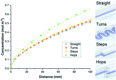
Computational fluid dynamics (CFD) was used to further investigate the effects of geometry on mass transport, with four channel designs studied: (i) straight, (ii) s-shaped turns (twenty 180° turns), (iii) stepped turns (10 right-angled ‘steps’), (iv) hops (10 right-angled ‘hops’) (Fig. 5). The latter two are identical in all respects, except the former is stepped within the plane of the spacer, the latter is stepped so it passes through the electrode. The channels all have the same depth (1 mm), width (1 mm) and path length (100 mm). Using a flow rate of 0.04 mL min−1 the velocity fields for the different flow channels were first calculated. One surface of the channel (shown in blue) was set to a concentration of 1 mol m−3, to allow transport from the surface into the bulk to be assessed. The concentration in the bulk solution, (entering at a concentration of 0 mol m−3), was calculated at intervals along the channel (Fig. 5). The straight channel, the turns and the stepped turns all performed similarly with an average concentration of between 0.51 and 0.54 mol m−3 at 100 mm along the channel. However, the channel with hops was calculated to have a much higher concentration in the bulk solution (0.66 mol m−3 at 100 mm). This further supports the hypothesis that hops increase the effective mass transfer, facilitating the removal of material from the electrode surface and into the bulk solution.
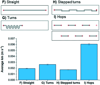
In order to obtain experimental mass transfer coefficients, four flow channels with the same electrode surface area were constructed (Fig. 6): a straight channel (F), one with s-shaped turns (G), one with stepped turns (H) and one with hops (I). The residence time distribution and axial dispersion coefficient (Fig. S17†) shows little difference across the 4 designs suggesting that the dynamics of the flow is not unduly influenced by the choice of flow channel design; this is confirmed from examining velocity vectors within the CFD simulations and is a consequence of the low Reynolds number flow The limiting current of an aqueous K3Fe(CN)6/K4Fe(CN)6 solution using graphite electrodes was determined and used to calculate the mass transfer coefficients of each flow channel (see ESI† for details) by gradually increasing the potential and measuring the current.22 The mass transfer coefficient was calculated from the potential at the limiting current. When using spacers F, G, and H, very similar mass transfer coefficients were obtained. By contrast, when using spacer I a mass transfer coefficient of 0.006 m s−1 was calculated, demonstrating that hops can increase the effective mass transfer significantly (Fig. 6). Values from the CFD simulations indicate a 10% penalty in pressure drop (Fig. S18†) for the stepped turns and hops over the straight and turns designs. The significant enhancement in mass transfer seen for spacer I (hops) is neither due to the pressure (pump energy) nor the mixing within the flow but due to the periodic switch in surface polarity as the flow hops through the electrode The effects of these different spacers (F–I) upon the synthesis of Cu1 is less stark, suggesting that this reaction is not entirely limited by mass transfer. This could be due to the mechanism of this reaction, which we have postulated previously,26 being significantly more complicated than the reduction of Fe3+ to Fe2+.
Conclusions
Different flow channel designs have been used to investigate the efficiency of mass transfer within a continuous electrochemical reactor. The increase in mass transfer has been exploited to give full conversion of L1 to Cu1 within an electrochemical flow reactor, whilst maintaining a small reactor volume. This effect was further investigated with CFD modelling and by calculating mass transfer coefficients empirically. These investigations demonstrate that hops, guiding the solution through an electrode, improve mass transfer significantly, possibly due to the constant replenishment of reactants at the electrode surfaces.Author contributions
The manuscript was written through contributions of all authors. All authors have given approval to the final version of the manuscript.Conflicts of interest
There are no conflicts of interest to declare.Acknowledgements
We are grateful to the EPSRC for helping to fund this work (EP/R009406/1). We would also like to thank AstraZeneca, Johnson-Matthey and Syngenta for funding HRS's CASE award.Notes and references
- M. Yan, Y. Kawamata and P. S. Baran, Chem. Rev., 2017, 117, 13230–13319 CrossRef CAS.
- M. D. Kärkäs, Chem. Soc. Rev., 2018, 47, 5786–5865 RSC.
- A. Wiebe, T. Gieshoff, S. Möhle, E. Rodrigo, M. Zirbes and S. R. Waldvogel, Angew. Chem., Int. Ed., 2018, 57, 5594–5619 CrossRef CAS PubMed.
- H. Lund, J. Electrochem. Soc., 2002, 149, S21 CrossRef CAS.
- M. B. Plutschack, B. Pieber, K. Gilmore and P. H. Seeberger, Chem. Rev., 2017, 117, 11796–11893 CrossRef CAS PubMed.
- M. Movsisyan, E. I. P. Delbeke, J. K. E. T. Berton, C. Battilocchio, S. V. Ley and C. V. Stevens, Chem. Soc. Rev., 2016, 45, 4892–4928 RSC.
- T. P. Nicholls, C. Schotten and C. E. Willans, Curr. Opin. Green Sustain. Chem., 2020, 100355 CrossRef.
- M. Atobe, H. Tateno and Y. Matsumura, Chem. Rev., 2018, 118, 4541–4572 CrossRef CAS PubMed.
- D. Pletcher, R. A. Green and R. C. D. Brown, Chem. Rev., 2018, 118, 4573–4591 CrossRef CAS.
- T. Noël, Y. Cao and G. Laudadio, Acc. Chem. Res., 2019, 52, 2858–2869 CrossRef.
- S. R. Waldvogel and B. Janza, Angew. Chem., Int. Ed., 2014, 53, 7122–7123 CrossRef CAS PubMed.
- L. R. Faulkner, J. Chem. Educ., 1983, 60, 262–264 CrossRef CAS.
- A. N. Colli, R. Toelzer, M. E. H. Bergmann and J. M. Bisang, Electrochim. Acta, 2013, 100, 78–84 CrossRef CAS.
- A. Storck and F. Coeuret, Electrochim. Acta, 1977, 22, 1155–1160 CrossRef CAS.
- A. Storck and D. Hutin, Electrochim. Acta, 1981, 26, 127–137 CrossRef CAS.
- L. Carlsson, B. Sandegren, D. Simonsson and M. Rihovsky, Proc. - Electrochem. Soc., 1983, 83–6, 8–16 CAS.
- C. F. Oduoza, A. A. Wragg and M. A. Patrick, Chem. Eng. J., 1997, 68, 145–155 CrossRef CAS.
- M. Lehmann, C. C. Scarborough, E. Godineau and C. Battilocchio, Ind. Eng. Chem. Res., 2020, 59, 7321–7326 CrossRef CAS.
- A. A. Folgueiras-Amador, A. E. Teuten, D. Pletcher and R. C. D. Brown, React. Chem. Eng., 2020, 5, 712–718 RSC.
- Y. Yu, P. Guo, J. S. Zhong, Y. Yuan and K. Y. Ye, Org. Chem. Front., 2019, 7, 131–135 RSC.
- V. Hessel, H. Löwe and F. Schönfeld, Chem. Eng. Sci., 2005, 60, 2479–2501 CrossRef CAS.
- C. Y. Wu and R. T. Tsai, Chem. Eng. J., 2013, 217, 320–328 CrossRef CAS.
- W. Jud, C. O. Kappe and D. Cantillo, Chem. Methods, 2021, 1, 36–41 CrossRef.
- M. R. Chapman, Y. M. Shafi, N. Kapur, B. N. Nguyen and C. E. Willans, Chem. Commun., 2015, 51, 1282–1284 RSC.
- T. P. Nicholls, R. A. Bourne, B. N. Nguyen, N. Kapur and C. E. Willans, Inorg. Chem., 2021, 60, 6976–6980 CrossRef CAS PubMed.
- C. Schotten, C. J. Taylor, R. A. Bourne, T. W. Chamberlain, B. N. Nguyen, N. Kapur and C. E. Willans, React. Chem. Eng., 2021, 6, 147–151 RSC.
Footnote |
| † Electronic supplementary information (ESI) available. See DOI: 10.1039/d1re00530h |
| This journal is © The Royal Society of Chemistry 2022 |

