 Open Access Article
Role of sulfur vacancies in MoS2 monolayers in stabilizing Co atoms for efficient CO oxidation†
Manman Li,
Tianchun Li and
Yu Jing *
*
Jiangsu Co-Innovation Centre of Efficient Processing and Utilization of Forest Resources, College of Chemical Engineering, Nanjing Forestry University, Nanjing 210037, China. E-mail: yujing@njfu.edu.cn
First published on 4th November 2022
Abstract
By performing first-principles calculations, a MoS2 monolayer with a Co atom doped at the sulfur defect (Co-SMoS2) was investigated as a single-atom catalyst (SAC) for CO oxidation. The Co atom is strongly constrained at the S-vacancy site of MoS2 without forming clusters by showing a high diffusion energy barrier, ensuring good stability to catalyze CO oxidation. The CO and O2 adsorption behavior on Co-SMoS2 surface and four reaction pathways, namely, the Eley–Rideal (ER), Langmuir–Hinshelwood (LH), trimolecular Eley–Rideal (TER) as well as the New Eley–Rideal (NER) mechanisms are studied to understand the catalytic activity of Co-SMoS2 for CO oxidation. The CO oxidation is more likely to proceed through the LH mechanism, and the energy barrier for the rate-limiting step is only 0.19 eV, smaller than that of noble metal-based SACs. Additionally, the NER mechanism is also favorable with a low energy barrier of 0.26 eV, indicating that the Co-SMoS2 catalyst can effectively promote CO oxidation at low temperatures. Our investigation demonstrates that the S-vacancy of MoS2 plays an important role in enhancing the stability and catalytic activity of Co atoms and Co-SMoS2 is predicted to be a promising catalyst for CO oxidation.
1. Introduction
Carbon monoxide (CO), originating from deficient combustion of carbon-containing fuels (such as coal and oil) from automobiles and industrial processes, is a widely distributed toxic gas in the atmosphere and can severely poison noble metal catalysts in fuel cells.1–3 The oxidation of CO to CO2 at low temperature is an effective strategy to relieve the problems caused by increased CO emission.4–7 Although the oxidation of CO is exothermic, the slow kinetics of this reaction demands the development of efficient catalysts to reduce the activation barrier.8 In the past decades, noble metal catalysts, such as Pt,9,10 Au,11,12 Pd,13,14 and Rh15,16 have been extensively explored and exhibit good catalytic activity for CO oxidation. However, these catalysts are expensive and typically require high reaction temperatures to operate efficiently, which prevents their large-scale commercial applications.13 Therefore, low-cost and efficient non-noble metal-based catalysts are highly demanded.In 2011, the preparation of homogeneous single Pt atoms on FeOX was first reported, and the Pt/FeOX catalysts showed good catalytic performance for CO oxidation.17 Thereafter, single-atom catalysts (SACs) have been rapidly developed as an important class of catalysts by showing good catalytic activity and selectivity for many reactions including CO oxidation, 18,19 oxygen reduction reactions (ORR),20,21 oxygen evolution reactions (OER),22,23 and hydrogen evolution reactions (HER).24,25 In contrast to conventional bulk metal catalysts, SACs are supported catalysts containing individual atoms isolated from each other as active centers, maximizing the utilization efficiency of metal atoms and reducing the cost.26 However, the isolated single metal atoms prone to be aggregated because of their high surface free energy and stable support materials are crucial to obtaining stable SACs with finely dispersed metal centers.
Recently, 2D materials have been widely studied as SAC supports because of their large surface area, tunable electronic properties and good stability, and some 2D SACs have been demonstrated to be promising catalysts for CO oxidation.27–34 Among them, 2D transition metal dichalcogenides (TMDCs) represented by MoS2 monolayers have drawn broad research interests because of their good stability and high experimental accessibility.35–38 Previous studies have demonstrated that doping transition metals on MoS2 monolayer can effectively tune the electronic structure and magnetic properties of MoS2,39 significantly enhancing the interaction between the catalyst and the adsorbed CO and O2 to facilitate CO oxidation.40–42 For instance, MoS2 monolayers with Co-doped on the pristine surface was demonstrated to show high catalytic activity for CO oxidation.43 However, aggregation of Co on pristine MoS2 will be inevitable due to the weak interaction between Co and the defect-free surface. In fact, the embedding of non-precious metals in the S vacancy of MoS2 can be experimentally feasible,44,45 because when 2D MoS2 was prepared using mechanical exfoliation or chemical vapor deposition techniques, S vacancies were the predominant defects and can even be controlled by using low-energy argon sputtering or electron irradiation techniques.46–48 Recently, Liu et al. synthesized MoS2 monolayer with cobalt-embedded at the sulfur vacancies by mixing chemically exfoliated MoS2 monolayer containing S vacancies with thiourea-like cobalt complexes,49 which exhibited high activity and stability for hydrodeoxygenation reaction and formaldehyde oxidation.50 Inspired by the good stability and high synthesizing feasibility of MoS2 monolayers with Co embedded in the sulfur vacancies, it is rather appealing to investigate their catalytic performance for CO oxidation, which has not been explored before.
In this work, we performed first-principles calculations to study the potential of MoS2 monolayers with individual Co atom embedded in the S vacancy (Co-SMoS2) as SACs for CO oxidation. The stability of Co-SMoS2 was first verified by estimating the diffusion of Co from the S vacancy to different adjacent surface sites. Then, the adsorption of CO and O2 on Co-SMoS2 was examined in comparison with that on defect-free MoS2 monolayer, defect-free MoS2 monolayer with a single Co atom decorated on the surface (Co/MoS2) and MoS2 monolayer containing S vacancies (MoS2-Sv). Four CO oxidation mechanisms on the Co-SMoS2, including, Eley–Rideal (ER), New Eley–Rideal (NER), Langmuir–Hinshelwood (LH) and trimolecular Eley–Rideal (TER) mechanisms, were systematically explored. The results indicate that Co-SMoS2 can facilitate CO oxidation through the LH and NER mechanisms by surmounting small energy barriers and show superior stability and catalytic activity than other examined MoS2 based structures because of the strong interaction between Co and sulfur vacancy, thus is predicted to be a promising catalyst for CO oxidation.
2. Computational methods
All calculations were carried out with the projected augmented wave (PAW) potential of spin-polarized density functional theory (DFT), as implemented in the Vienna Ab initio Simulation Package (VASP).51–53 The generalized gradient approximation (GGA) method with Perdew–Burke–Ernzerhof (PBE) was adopted to depict exchange–correlation potential.54 The van der Waals (vdWs) interactions between the adsorbing molecules and the monolayer were depicted by using the DFT-D3 method proposed by Grimme.55 The plane-wave cutoff energy was set as 420 eV and the Monkhorst–Pack grid of 3 × 3 × 1 and 5 × 5 × 1 k-points grid were used for the geometry optimization and the calculation of electronic properties. The system is considered to be self-consistent when the total energy and the magnitude of the force on each atom are below 10−5 eV and 0.01 eV Å−1, respectively. The vacuum layer of the MoS2 monolayer was set to be 20 Å to avoid interlayer interactions. The minimum energy paths for CO oxidation reaction were searched by the climbing image nudged elastic band (CI-NEB) and dimer method,56–58 and the transition state (TS) geometries were obtained after vibrational analysis. The lattice parameter of MoS2 monolayer was optimized to be 3.17 Å, which agrees well with the results of previously experimental and theoretical studies.43,59 The binding energy (Eb) of Co atom in Co-SMoS2 was calculated by| Eb = ECo-SMoS2 − EMoS2-Sv − ECo | (1) |
The adsorption energy (Eads) of different adsorbates on different substrates was calculated according to
| Eads = Esub+gas − Esub − Egas | (2) |
To investigate whether the CO oxidation performance is affected by the doping concentration of Co, we constructed a 2 × 2, 3 × 3, 4 × 4 and 5 × 5 supercell containing one Co atom embedded at the S vacancy, corresponding to the atomic embedding concentration of 25%, 11%, 6% and 4%, respectively. However, it turned out that these four supercells gave identical Eb values of Co and Eads for CO and O2 (Table S1†), indicating that the concentration of Co shows negligible influence on their catalytic activity. Therefore, considering the computational accuracy and efficiency, the 4 × 4 MoS2 supercell is used for all catalysis calculations unless stated otherwise.
The reaction energy barriers (Ebar) and reaction energy (ΔE) for the elementary steps of CO oxidation reaction was defined as
| Ebar = ETS − EIS | (3) |
| ΔE = EFS − EIS | (4) |
3. Results and discussion
3.1 Structure and stability of Co-SMoS2
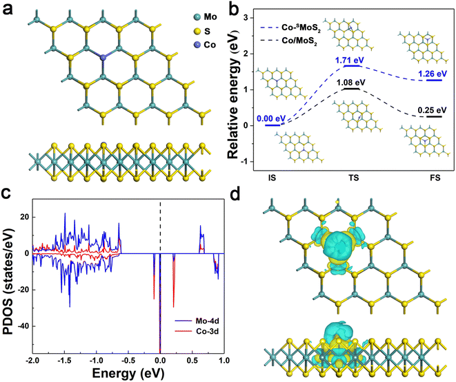
The structural and electronic properties of Co-SMoS2 were first studied. As shown in Fig. 1a, the Co atom is embedded at the S vacancy forming three covalent bonds with its adjacent Mo atoms and the average bond length of Co–Mo is 2.51 Å. The Eb of Co atom is −4.39 eV, indicating a strong interaction of Co atom with the neighboring Mo atoms, which is stronger than that on the defect-free MoS2 surface (−3.28 eV). In view of the cohesion energy of bulk Co (−4.39 eV),60 it can be expected that the embedded Co atoms are less likely to aggregate to form large clusters on defective MoS2 compared to the defect-free surface. To gain a deep understanding of the stability of Co-SMoS2, we estimated the migration of Co atom from the S vacancy to a nearby hollow site. As shown in Fig. 1b, the calculated diffusion process is endothermic (1.26 eV) with a high diffusion energy barrier of 1.71 eV. In contrast, the Eb of Co atom on two different surface sites of defect-free MoS2 only differs in 0.25 eV and the diffusion energy barrier of Co is 1.08 eV. The results suggest that the S vacancies on MoS2 play an important role in stabilizing the Co atoms and inhibiting their further aggregation.The spin polarized partial density of states (PDOS) projected on the Co-3d and adjacent Mo-4d orbitals were plotted in comparison with the total DOS to understand the electronic structure of Co-SMoS2. As shown in Fig. 1c, the embedding of Co atom induces impurity states around the Fermi energy level, contributing to a reduced band gap (0.20 eV) of Co-SMoS2 compared to the pristine MoS2 monolayer. The pronounced hybridization between the Co-3d orbital and the adjacent Mo-4d orbitals around the Fermi energy level is responsible for the strong interaction between Co and defective MoS2. Bader charge analysis61 shows that there is about 0.14|e| charge transferred from the Co atom to the adjacent Mo atoms, which can be visualized by the charge density difference (CDD) analysis. As illustrated in Fig. 1d, there is obvious electron depletion (cyan) and electron accumulation (yellow) at the Co and the neighboring Mo atoms, respectively. The strong interaction and significant charge reallocation between Co and defective MoS2 will favor the good stability and high activity of Co-SMoS2 for efficient CO oxidation.
3.2 Activation of gas molecules on different MoS2 monolayers
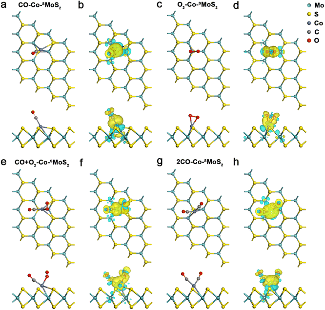
Before exploring the mechanism of CO oxidation on Co-SMoS2 surfaces, the adsorption and co-adsorption of the reactants (CO and O2) were first examined. The most preferred adsorption site for each molecule was decided by considering different adsorption configurations. The CO molecule prefers to be adsorbed at the Co site of Co-SMoS2 with the end-on configuration, as exhibited in Fig. 2a. The calculated Eads is −1.78 eV and the bond length of Co–C is 1.79 Å, indicating a strong interaction between the adsorbed CO and the Co-SMoS2. Bader charge analysis indicates about 0.20|e| charge transferred from Co-SMoS2 to CO and CDD analysis (Fig. 2b) illustrates the electron accumulation at the Co–C bond. The PDOS analysis (Fig. S2a, ESI†) shows that there is obvious hybridization between the Co-3d orbital and the C-2p and O-2p orbitals near the Fermi level. The significant charge transfer and strong hybridization between Co atoms and the adsorbed CO molecule indicate that the CO molecule can been effectively activated by the Co, leading to elongated C–O bond from 1.14 to 1.16 Å.The most stable adsorption configuration of O2 on Co-SMoS2 can be seen in Fig. 2c. It can be found that the O2 molecule is adsorbed at the Co site in a side-on manner, forming two Co–O bonds with the bond length of 1.89 Å, and the calculated Eads of −1.64 eV is a little lower than that of CO. The Bader charge analysis shows that there is about 0.46|e| charge transferred from the Co-SMoS2 to O2, which will occupy the 2π* orbital of O2 and contribute to the elongation of the O–O bond from 1.23 to 1.36 Å. As shown in Fig. 2d, there is significant electron accumulation at the adsorbed O2. These results indicate that the O2 can be highly activated at the Co site of Co-SMoS2. Moreover, the hybridization (Fig. S2b, ESI†) between the Co-3d state and the O2-2p state also suggests the significant interaction of Co atom with the adsorbed O2 molecule.
The adsorption of CO and O2 on defect-free MoS2, Co/MoS2 and MoS2-Sv surfaces (Fig. S3 and Table S2, ESI†) were also examined as comparisons. It can be found that the adsorption of CO and O2 on defect-free MoS2 is rather weak and the Eads is as small as −0.15 and −0.09 eV, respectively. Thus, CO and O2 can only be physisorbed on defect-free MoS2 monolayer. On the MoS2-Sv surface, CO and O2 molecules are adsorbed at the S vacancy in an end-on and side-on manner, respectively. The C–O bond of CO and the O–O bond of O2 is elongated to 1.16 and 1.44 Å and the Eads is −1.24 and −2.14 eV, respectively. Therefore, the S vacancy of MoS2-Sv prefers to be occupied by O2 instead of CO. On the Co/MoS2 surface, the Eads of CO and O2 is −2.30 and −1.90 eV, respectively, and the C–O and O–O bond length increase to 1.16 and 1.35 Å, respectively. It can be found that surface defects play important roles in enhancing the ability of MoS2 monolayer to activate surface molecules and different kinds of defects contribute to different activation of CO and O2, which will result in different catalytic performances for CO oxidation.
To better reveal the mechanism of CO oxidation reaction on the surface of different catalysts, the co-adsorption of the reactants is also investigated because the preferred adsorption manner can determine the pathway of CO oxidation. Fig. 2e and g show the most stable co-adsorption configurations of CO + O2 and two CO molecules on Co-SMoS2, respectively. The co-adsorption energy of CO + O2 is calculated to be −2.04 eV, more negative than that of the isolate adsorption of CO or O2, indicating that co-adsorption of CO + O2 molecules on Co-SMoS2 is more favored. The co-adsorption of two CO molecules is also examined which turns out to be more favorable than that of one CO molecule alone, where a V-type OCCoCO structure was formed with an Eads of −2.81 eV. There is an obvious charge accumulation and depletion between the Co atom and the adsorbed CO + O2 or 2CO molecules (Fig. 2f and h). Thus, in terms of Eads, the co-adsorption of 2CO molecules is even more feasible than that of CO + O2 molecules on Co-SMoS2.
For the defect-free MoS2, the adsorption of CO + O2 and 2CO remains weak with the Eads of −0.28 eV and −0.33 eV, respectively (Fig. S4a and Table S2, ESI†); for the MoS2-Sv surface, the second gas molecule is difficult to be adsorbed after the adsorption of one molecule of CO or O2 on the S vacancy (Fig. S4b, ESI†), indicating that the S vacancy tends to be oxidized at the exposure of CO or O2, which will cause catalyst deactivation. Thus we further examined the robustness of MoS2-Sv by estimating the feasibility of removing the O* species at the S vacancy using a molecule of CO (Fig. S5, ESI†). The results show that this step (CO + O* → CO2) requires to conquer a high energy barrier of 2.17 eV and this elementary reaction is endothermic with the reaction energy of 0.83 eV, indicating that the O* species is difficult to be removed and the S vacancy will be definitely poisoned. The co-adsorption configurations of CO + O2 and 2CO on Co/MoS2 are similar to those on Co-SMoS2 and exhibit the Eads of −2.67 and −3.29 eV, respectively (Fig. S4c, ESI†). Since defect-free MoS2 shows weak adsorption of the reactants and MoS2-Sv tends to be oxidized by the reactants, they are both unfavorable for subsequent CO oxidation, and thus are excluded from potential catalysts for further discussion. We only examined the detailed CO oxidation process on Co-SMoS2 and Co/MoS2 in subsequent calculations unless stated otherwise.
The Eads of CO2 on Co-SMoS2 and Co/MoS2 was then examined since CO2 is the final product of CO oxidation, which turns out to be −0.48 eV for both cases (Fig. S3c, d and Table S2, ESI†). This indicates that the adsorption of CO2 molecule on Co-SMoS2 and Co/MoS2 is feeble and can be desorbed from the surface site at room temperature. Furthermore, when the free O2 or CO molecules approach to the Co-SMoS2 with CO2 pre-adsorbed, the CO2 is automatically desorbed from the catalyst (Fig. S6, ESI†). Thus, even in the presence of abundant CO2, O2 and CO molecules can still reoccupy the active site to promote the next step of CO oxidation.
3.3 CO oxidation over Co-SMoS2
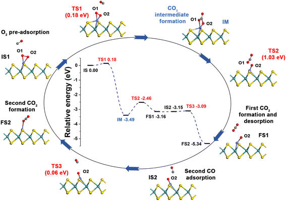
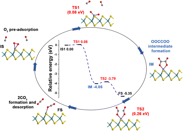
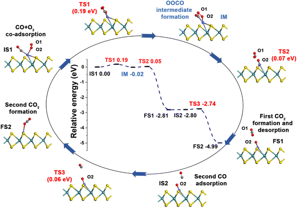
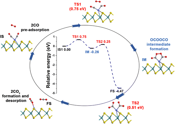
Generally, CO oxidation reactions can occur through three traditional pathways, namely, the ER, LH, and TER mechanisms,28,33 which are determined by the initial adsorption configuration of the reactant molecules. For the ER mechanism, O2 is pre-adsorbed at the reaction site, following by the approaching of CO to form the CO3* intermediates (IM) or directly to produce a CO2, leaving a O* species. The LH mechanism is facilitated by the co-adsorption of CO and O2 molecules at the reaction site to form peroxide-like OOCO* complexes, which then dissociate into CO2 and O*. The TER mechanism will proceed when the O2 reacts with the co-adsorbed bi-molecular CO to form OCOOCO* (IM), which subsequently turns into two CO2 molecules. As mentioned in Section 3.2, the adsorption energy of CO (−1.78 eV) and O2 (−1.64 eV) on Co-SMoS2 are similar, so that different reactants may be adsorbed at the active site when the reactant concentrations vary, and we next discuss the possible reaction mechanisms for different reactant concentrations.After examining all the four possible mechanisms for CO oxidation on Co-SMoS2 monolayer, namely ER, LH, TER and NER mechanisms, we found the LH mechanism to be most favorable pathway for CO oxidation, showing the smallest energy barrier of 0.19 eV, followed by the NER mechanism (0.26 eV). Remarkably, the three pathways, namely NER, LH and TER, all show the RDS energy barrier well below 1.0 eV, indicating that CO oxidation can be facilitated on the surface of Co-SMoS2 at low temperatures. The performance of Co/MoS2 monolayer is finally examined as a comparison of Co-SMoS2. It can be found that the LH mechanism (Fig. S7, ESI†) is also the most preferred pathway for CO oxidation on Co/MoS2 by showing an energy barrier of 0.62 eV. These results are highly consistent with those of the previous study (LH, 0.57 eV)43 demonstrating the reliability of our calculations. As a result, our investigations indicate that Co-SMoS2 is a promising catalyst for CO oxidation and shows better stability and catalytic activity than that of Co/MoS2.
The preferred LH mechanism for CO oxidation on Co-SMoS2 can be understood by analyzing the PDOS of the IS1 and TS1 structures along the LH mechanism on Co-SMoS2 (Fig. S8, ESI†). As shown in Fig. S8a,† the 2π* orbital of the adsorbed O2 is partially occupied and Bader charge analysis indicates that there is about 0.36|e| charge transferred from Co to O2, indicating that the O–O bond is activated by Co of Co-SMoS2. In addition, there is a significant overlap between the 5σ* and 2π* states of O2 and the states of Co atom, demonstrating the strong interaction between O2 and Co. From IS1 to TS1, there is about 0.03|e| charge transfer from CO to O2 and the 5σ* state of O2 partially shifts closer to the Fermi level (Fig. S8b†). These results indicate that the co-adsorption of CO can further weaken the O1–O2 bond O2. It can also be found that the 5σ and 1π states of CO and O2 are broadened, indicating the formation of OCOO (IM). The above results indicate that the LH mechanism is favored by the activation of the O1–O2 bond by the embedded Co atom and the co-adsorbed CO.
To better evaluate the catalytic activity of Co-SMoS2 for CO oxidation, we compared the performance of Co-SMoS2 with that of other noble metal-based SACs and the energy barriers of the RDS over various catalysts are presented in Table 1. The energy barrier for CO oxidation on Co-SMoS2 can be found to be lower than that of other reported noble metal-based SACs, indicating that Co-SMoS2 is a highly promising SAC candidate for CO oxidation by showing higher catalytic activity and lower cost than many noble metal-based SACs.
4. Conclusions
As a summary, by performing DFT calculations, we have studied the possibility of using Co-embedded MoS2 monolayers as SACs for CO oxidation. The results show that Co atoms embedded at the S vacancies of MoS2 can form stable SACs without aggregating due to the strong hybridization between Co and Mo atoms, which is more robust than the Co doped defect-free MoS2 surface. The adsorption manner of CO and O2 molecules on Co-SMoS2 can decide the reaction pathway of CO oxidation and the co-adsorption of CO + O2 and two CO are both favorable at the Co site of Co-SMoS2. The four possible reaction pathways, including ER, LH, TER and NER mechanisms for CO oxidation on Co-SMoS2 were discussed and the results show that the oxidation of CO can be facilitated through the LH mechanism by overcoming a small energy barrier of 0.19 eV, which is superior to many noble-metal based SACs. By exhibiting good stability, high catalytic activity, and low-cost characteristics, Co-SMoS2 is predicted to serve as a promising non-noble metal-based SAC candidate for efficient catalytic CO oxidation. Since Co-SMoS2 have been experimentally synthesized, the practice of using this material for CO oxidation can be expected in the near future.Conflicts of interest
There are no conflicts to declare.Acknowledgements
We appreciate the financial support in China by Natural Science Foundation of Jiangsu Province of China (no. BK20190744) and National Natural Science Foundation of China (no. 21903046, 22222304).References
- J. J. Baschuk and X. Li, Int. J. Energy Res., 2001, 25, 695–713 CrossRef CAS.
- F. Mariño, C. Descorme and D. Duprez, Appl. Catal., B, 2004, 54, 59–66 CrossRef.
- L. Birry, J. H. Zagal and J.-P. Dodelet, Electrochem. Commun., 2010, 12, 628–631 CrossRef CAS.
- L. Cao, W. Liu, Q. Luo, R. Yin, B. Wang, J. Weissenrieder, M. Soldemo, H. Yan, Y. Lin, Z. Sun, C. Ma, W. Zhang, S. Chen, H. Wang, Q. Guan, T. Yao, S. Wei, J. Yang and J. Lu, Nature, 2019, 565, 631–635 CrossRef CAS PubMed.
- H. Zhang, S. Fang and Y. H. Hu, Catal. Rev.: Sci. Eng., 2022, 64, 491–532 CrossRef CAS.
- B. Qiao, J. Liu, Y.-G. Wang, Q. Lin, X. Liu, A. Wang, J. Li, T. Zhang and J. Liu, ACS Catal., 2015, 5, 6249–6254 CrossRef CAS.
- H. Su and Y. H. Hu, Chem. Eng. J., 2020, 402, 126235 CrossRef CAS.
- T. Bunluesin, H. Cordatos and R. J. Gorte, J. Catal., 1995, 157, 222–226 CrossRef CAS.
- A. Alavi, P. Hu, T. Deutsch, P. L. Silvestrelli and J. Hutter, Phys. Rev. Lett., 1998, 80, 3650–3653 CrossRef CAS.
- A. Beniya, S. Higashi, N. Ohba, R. Jinnouchi, H. Hirata and Y. Watanabe, Nat. Commun., 2020, 11, 1888 CrossRef CAS PubMed.
- Y. G. Wang, Y. Yoon, V. A. Glezakou, J. Li and R. Rousseau, J. Am. Chem. Soc., 2013, 135, 10673–10683 CrossRef CAS PubMed.
- L. Li, Y. Gao, H. Li, Y. Zhao, Y. Pei, Z. Chen and X. C. Zeng, J. Am. Chem. Soc., 2013, 135, 19336–19346 CrossRef CAS PubMed.
- C. J. Zhang and P. Hu, J. Am. Chem. Soc., 2001, 123, 1166–1172 CrossRef CAS PubMed.
- F. C. H. Lim, J. Zhang, H. Jin, M. B. Sullivan and P. Wu, Appl. Catal., A, 2013, 451, 79–85 CrossRef CAS.
- H. Öström, H. Öberg, H. Xin, J. LaRue, M. Beye, M. Dell’Angela, J. Gladh, M. L. Ng, J. A. Sellberg, S. Kaya, G. Mercurio, D. Nordlund, M. Hantschmann, F. Hieke, D. Kühn, W. F. Schlotter, G. L. Dakovski, J. J. Turner, M. P. Minitti, A. Mitra, S. P. Moeller, A. Föhlisch, M. Wolf, W. Wurth, M. Persson, J. K. Nørskov, F. Abild-Pedersen, H. Ogasawara, L. G. M. Pettersson and A. Nilsson, Science, 2015, 347, 978–982 CrossRef PubMed.
- O. Khalid, T. Weber, G. Drazic, I. Djerdj and H. Over, J. Phys. Chem. C, 2020, 124, 18670–18683 CrossRef CAS.
- B. Qiao, A. Wang, X. Yang, L. F. Allard, Z. Jiang, Y. Cui, J. Liu, J. Li and T. Zhang, Nat. Chem., 2011, 3, 634–641 CrossRef CAS PubMed.
- L. Nie, D. Mei, H. Xiong, B. Peng, Z. Ren, X. I. P. Hernandez, A. DeLaRiva, M. Wang, M. H. Engelhard, L. Kovarik, A. K. Datye and Y. Wang, Science, 2017, 358, 1419–1423 CrossRef CAS PubMed.
- T. Kropp and M. Mavrikakis, ACS Catal., 2019, 9, 6864–6868 CrossRef CAS.
- J. Hu, W. Liu, C. Xin, J. Guo, X. Cheng, J. Wei, C. Hao, G. Zhang and Y. Shi, J. Mater. Chem. A, 2021, 9, 24803–24829 RSC.
- Z. Zhu, H. Yin, Y. Wang, C.-H. Chuang, L. Xing, M. Dong, Y.-R. Lu, G. Casillas-Garcia, Y. Zheng, S. Chen, Y. Dou, P. Liu, Q. Cheng and H. Zhao, Adv. Mater., 2020, 32, 2004670 CrossRef CAS PubMed.
- X. Li, P. Cui, W. Zhong, J. Li, X. Wang, Z. Wang and J. Jiang, ChemComm, 2016, 52, 13233–13236 RSC.
- S. Dou, C.-L. Dong, Z. Hu, Y.-C. Huang, J.-l. Chen, L. Tao, D. Yan, D. Chen, S. Shen, S. Chou and S. Wang, Adv. Funct. Mater., 2017, 27, 1702546 CrossRef.
- Y. Xue, B. Huang, Y. Yi, Y. Guo, Z. Zuo, Y. Li, Z. Jia, H. Liu and Y. Li, Nat. Commun., 2018, 9, 1460 CrossRef PubMed.
- X.-P. Yin, H.-J. Wang, S.-F. Tang, X.-L. Lu, M. Shu, R. Si and T.-B. Lu, Angew. Chem., Int. Ed., 2018, 57, 9382–9386 CrossRef CAS PubMed.
- X.-F. Yang, A. Wang, B. Qiao, J. Li, J. Liu and T. Zhang, Acc. Chem. Res., 2013, 46, 1740–1748 CrossRef CAS PubMed.
- S. Lin, X. Ye, R. S. Johnson and H. Guo, J. Phys. Chem. C, 2013, 117, 17319–17326 CrossRef CAS.
- S. Wang, J. Li, Q. Li, X. Bai and J. Wang, Nanoscale, 2020, 12, 364–371 RSC.
- E. W. McFarland and H. Metiu, Chem. Rev., 2013, 113, 4391–4427 CrossRef CAS PubMed.
- J. Liu, ACS Catal., 2017, 7, 34–59 CrossRef CAS.
- Y.-H. Lu, M. Zhou, C. Zhang and Y. P. Feng, J. Phys. Chem. C, 2009, 113, 20156–20160 CrossRef CAS.
- E. H. Song, Z. Wen and Q. Jiang, J. Phys. Chem. C, 2011, 115, 3678–3683 CrossRef CAS.
- Y. Tang, W. Chen, H. Chai, G. Zhao, Y. Li, D. Ma and X. Dai, J. Phys. Chem. C, 2019, 123, 10926–10939 CrossRef CAS.
- K. Mao, L. Li, W. Zhang, Y. Pei, X. C. Zeng, X. Wu and J. Yang, Sci. Rep., 2014, 4, 5441 CrossRef CAS PubMed.
- S. Manzeli, D. Ovchinnikov, D. Pasquier, O. V. Yazyev and A. Kis, Nat. Rev. Mater., 2017, 2, 17033 CrossRef CAS.
- K. F. Mak, C. Lee, J. Hone, J. Shan and T. F. Heinz, Phys. Rev. Lett., 2010, 105, 136805 CrossRef PubMed.
- J. Mao, Y. Wang, Z. Zheng and D. Deng, Front. Phys., 2018, 13, 138118 CrossRef.
- Q. H. Wang, K. Kalantar-Zadeh, A. Kis, J. N. Coleman and M. S. Strano, Nat. Nanotechnol., 2012, 7, 699–712 CrossRef CAS PubMed.
- Y. Fan, J. Zhang, Y. Qiu, J. Zhu, Y. Zhang and G. Hu, Comput. Mater. Sci., 2017, 138, 255–266 CrossRef CAS.
- D. Ma, W. Ju, T. Li, X. Zhang, C. He, B. Ma, Z. Lu and Z. Yang, Appl. Surf. Sci., 2016, 383, 98–105 CrossRef CAS.
- D. Ma, W. Ju, T. Li, G. Yang, C. He, B. Ma, Y. Tang, Z. Lu and Z. Yang, Appl. Surf. Sci., 2016, 371, 180–188 CrossRef CAS.
- Y.-Y. Chen, M. Dong, J. Wang and H. Jiao, J. Phys. Chem. C, 2010, 114, 16669–16676 CrossRef CAS.
- S. Liu and S. Huang, Appl. Surf. Sci., 2017, 425, 478–483 CrossRef CAS.
- D. Ma, Y. Tang, G. Yang, J. Zeng, C. He and Z. Lu, Appl. Surf. Sci., 2015, 328, 71–77 CrossRef CAS.
- A. Sharma, A. Srivastava, M. Husain and M. S. Khan, J. Mater. Sci., 2018, 53, 9578–9588 CrossRef CAS.
- Q. Ma, P. M. Odenthal, J. Mann, D. Le, C. S. Wang, Y. Zhu, T. Chen, D. Sun, K. Yamaguchi, T. Tran, M. Wurch, J. L. McKinley, J. Wyrick, K. Magnone, T. F. Heinz, T. S. Rahman, R. Kawakami and L. Bartels, J. Phys.: Condens. Matter, 2013, 25, 252201 CrossRef PubMed.
- H.-P. Komsa, J. Kotakoski, S. Kurasch, O. Lehtinen, U. Kaiser and A. V. Krasheninnikov, Phys. Rev. Lett., 2012, 109, 035503 CrossRef PubMed.
- H.-P. Komsa, S. Kurasch, O. Lehtinen, U. Kaiser and A. V. Krasheninnikov, Phys. Rev. B: Condens. Matter Mater. Phys., 2013, 88, 035301 CrossRef.
- G. Liu, A. W. Robertson, M. M.-J. Li, W. C. H. Kuo, M. T. Darby, M. H. Muhieddine, Y.-C. Lin, K. Suenaga, M. Stamatakis, J. H. Warner and S. C. E. Tsang, Nat. Chem., 2017, 9, 810–816 CrossRef CAS PubMed.
- T. Jitwatanasirikul, T. Roongcharoen, C. Chitpakdee, S. Jungsuttiwong, P. Poldorn, K. Takahashi and S. Namuangruk, New J. Chem., 2021, 45, 17407–17417 RSC.
- P. E. Blöchl, Phys. Rev. B: Condens. Matter Mater. Phys., 1994, 50, 17953–17979 CrossRef PubMed.
- G. Kresse and D. Joubert, Phys. Rev. B: Condens. Matter Mater. Phys., 1999, 59, 1758–1775 CrossRef CAS.
- G. Kresse and J. Furthmüller, Comput. Mater. Sci., 1996, 6, 15–50 CrossRef CAS.
- J. P. Perdew, K. Burke and M. Ernzerhof, Phys. Rev. Lett., 1996, 77, 3865–3868 CrossRef CAS PubMed.
- S. Grimme, S. Ehrlich and L. Goerigk, J. Comput. Chem., 2011, 32, 1456–1465 CrossRef CAS PubMed.
- B. Uberuaga and H. Jonsson, J. Chem. Phys., 2000, 113, 9901–9904 CrossRef.
- G. Henkelman and H. Jónsson, J. Chem. Phys., 1999, 111, 7010–7022 CrossRef CAS.
- J. Kästner and P. Sherwood, J. Chem. Phys., 2008, 128, 014106 CrossRef PubMed.
- D. Yang, S. J. Sandoval, W. M. R. Divigalpitiya, J. C. Irwin and R. F. Frindt, Phys. Rev. B: Condens. Matter Mater. Phys., 1991, 43, 12053–12056 CrossRef CAS PubMed.
- M. Chen, X.-B. Yang, J. Cui, J.-J. Tang, L.-Y. Gan, M. Zhu and Y.-J. Zhao, Int. J. Hydrogen Energy, 2012, 37, 309–317 CrossRef CAS.
- G. Henkelman, A. Arnaldsson and H. Jónsson, Comput. Mater. Sci., 2006, 36, 354–360 CrossRef.
- G. Xu, R. Wang, Z. Lu, D. Ma and Z. Yang, J. Phys. Chem. C, 2018, 122, 23481–23492 CrossRef CAS.
- F. Li and Z. Chen, Nanoscale, 2018, 10, 15696–15705 RSC.
- Y. Tang, Z. Yang and X. Dai, Phys. Chem. Chem. Phys., 2012, 14, 16566–16572 RSC.
- M. D. Esrafili, P. Nematollahi and R. Nurazar, Superlattices Microstruct., 2016, 92, 60–67 CrossRef CAS.
- Y.-H. Lu, M. Zhou, C. Zhang and Y. P. Feng, J. Phys. Chem. C, 2009, 113, 20156–20160 CrossRef CAS.
- M. D. Esrafili and S. Asadollahi, ChemistrySelect, 2018, 3, 9181–9188 CrossRef CAS.
- Z. Lu, P. Lv, J. Xue, H. Wang, Y. Wang, Y. Huang, C. He, D. Ma and Z. Yang, RSC Adv., 2015, 5, 84381–84388 RSC.
- Y. Tang, X. Dai, Z. Yang, L. Pan, W. Chen, D. Ma and Z. Lu, Phys. Chem. Chem. Phys., 2014, 16, 7887–7895 RSC.
- G. Xu, R. Wang, Y. Ding, Z. Lu, D. Ma and Z. Yang, J. Phys. Chem. C, 2018, 122, 23481–23492 CrossRef CAS.
Footnote |
| † Electronic supplementary information (ESI) available. See DOI: https://doi.org/10.1039/d2ra06261e |
| This journal is © The Royal Society of Chemistry 2022 |

