 Open Access Article
MoO2 nanosheets anchored with Co nanoparticles as a bifunctional electrocatalytic platform for overall water splitting†
Lu Xiaa,
Yanjun Lia,
Hao Songbc,
Xingxing Lib,
Wenjie Gonga,
Xinyu Jianga,
Mehran Javanbakht d,
Xuming Zhang
 b,
Biao Gao
 *b and
Paul K. Chu
 *c
*c
aThe College of Resources and Environment Engineering and Hubei Key Laboratory for Efficient Utilization and Agglomeration of Metallurgic Mineral Resources, Wuhan University of Science and Technology, Wuhan 430081, China
bThe State Key Laboratory of Refractories and Metallurgy and Institute of Advanced Materials and Nanotechnology, Wuhan University of Science and Technology, Wuhan 430081, China. E-mail: gaobiao@wust.edu.cn
cDepartment of Physics, Department of Materials Science and Engineering, Department of Biomedical Engineering, City University of Hong Kong, Tat Chee Avenue, Kowloon, Hong Kong, China. E-mail: paul.chu@cityu.edu.hk
dRenewable Energy Research Center, Amirkabir University of Technology, Tehran, Iran
First published on 5th December 2022
Abstract
Electrochemical water splitting is one of the potential commercial techniques to produce clean hydrogen energy because of the high efficiency and environmental friendliness. However, development of low-cost bifunctional electrocatalysts that can replace Pt-based catalysts for the hydrogen evolution reaction (HER) and oxygen evolution reaction (OER) is challenging. Herein, Co nanoparticles (NPs) are anchored on MoO2 nanosheets (Co/MoO2) by thermal reduction of the CoMoO4 nanosheet array in Ar/H2. The uniformly distributed Co NPs improve the electron transfer capability and modulate the surface states of the MoO2 nanosheets to enhance hydrogen desorption and HER kinetics. Moreover, the Co/MoO2 composite is beneficial to the interfacial structure and the MoO2 nanosheets prevent aggregation of Co NPs to improve the intrinsic OER characteristics in the alkaline electrolyte. As a result, the Co/MoO2 electrocatalyst shows low HER and OER overpotentials of 178 and 318 mV at a current density of 10 mA cm−2 in 1 M KOH. The electrolytic cell consisting of the bifunctional Co/MoO2 electrodes shows a small voltage of 1.72 V for a current density of 10 mA cm−2 in overall water splitting.
1 Introduction
Hydrogen (H2) energy is one of the candidates to replace fossil fuels because of its environmental friendliness, small weight, and high energy density. Electrocatalytic water splitting is one of the preferred means to produce H2 and O2.1–3 Water splitting includes the hydrogen evolution reaction (HER) and oxygen evolution reaction (OER) that require proper catalysts to boost efficiency. Some noble metals such as Pt and Pd possess high electrocatalytic activity and low overpotentials in HER and noble metal oxide catalysts such as RuO2 and IrO2 are common catalysts for OER. However, the high cost and natural scarcity of these noble materials hamper large-scale commercial application.4–6 HER can take place in both acid and base media but OER is undesirable in acidic electrolytes. Hence, preparation of efficient bifunctional noble-metal-free electrocatalysis for both HER and OER in alkaline media is challenging albeit of prime importance.Owing to the high abundance and low cost, rutile molybdenum dioxide (MoO2) is garnered interest in water splitting7 and nanostructures such as nanoparticles,8 nanobelts,9 nanosheets,10 nanoflowers,11 nanowires12 and hierarchical nanoarrays13 have been developed to improve H2 evolution by increasing the surface area and increasing the reaction sites. Chen et al. have demonstrated that the Mo atom in MoO2 is a high d-band center because of expansion of the Mo lattice upon incorporation of oxygen, resulting in unfavorite H2 kinetics and poor H2 evolution activity on MoO2.14 Introducing transition metals to fill the empty d orbitals of Mo can weaken the Mo–H binding energy and improve the hydrogen evolution efficiency.15–18 Zhao et al. have constructed a CoP and MoO2 heterostructure to coordinate interface electrons and accelerate dissociation of water and adsorption of hydrogen.19 Recent research activities have focused on improving the HER performance of MoO2 catalysts but the OER characteristics have not been studied extensively.
Herein, MoO2 nanosheets are anchored with Co nanoparticles (Co/MoO2) to serve as bifunctional electrocatalysts for both HER and OER by reducing CoMoO4 grafted on a carbon cloth in the Ar/H2 atmosphere. In this process, CoMoO4 is separated in situ to form the Co/MoO2 heterojunction with abundant Co and MoO2 interface consequently improving the HER and OER properties simultaneously, as demonstrated by low overpotentials of 178 mV and 318 mV to achieve a current density of 10 mA cm−2 together with small Tafel slopes of 102.6 mV dec−1 and 93.9 mV dec−1 in HER and OER in 1 M KOH, respectively. The electrolytic cell assembled with the bifunctional Co/MoO2 electrocatalyst shows a low overall water splitting voltage of 1.72 V for a current density of 10 mA cm−2. The results reveal a promising non-noble catalystic platform for low-cost and high-efficiency H2 and O2 production.
2 Experimental
2.1 Preparation of Co/MoO2 nanoarrays, Co, and MoO2
The carbon cloth (CC) pretreated with ethanol and acetone was soaked overnight in a nitric acid solution to enrich the surface oxygen-containing functional groups. After rinsing with ultrapure water, the CC was dried in a 60 °C oven. 0.1765 g of (NH4)6Mo7O24, 0.249 g of Co(CH3COO)2, 0.12 g of (NH2)2CO, and 0.185 g of NH4F were dissolved in 30 mL of ultrapure water ultrasonically for 30 min, transferred to a 50 mL Teflon-lined stainless autocalve containing the CC, and heated to 150 °C for 6 h. After cooling to room temperature, the CC was taken out, rinsed three times with ultrapure water, and dried in a vacuum freeze-dryer for 12 h. Afterwards, the sample was pyrolyzed at 400 °C for 2 h at a heating rate of 5 °C min−1 in argon (Ar) and then Ar/H2 (volume ratio: 90![[thin space (1/6-em)]](https://www.rsc.org/images/entities/char_2009.gif) :
:![[thin space (1/6-em)]](https://www.rsc.org/images/entities/char_2009.gif) 10) at 550 °C for 2 h at a ramping rate of 5 °C min−1 to form the Co/MoO2 nanoarrays.
10) at 550 °C for 2 h at a ramping rate of 5 °C min−1 to form the Co/MoO2 nanoarrays.
Synthesis of Co proceeded in two steps. The CC was electrodeposited in a 0.1 M cobalt nitrate solution to produce Co(OH)2 (ref. 20) and then annealed in Ar/H2 (volume ratio: 90![[thin space (1/6-em)]](https://www.rsc.org/images/entities/char_2009.gif) :
:![[thin space (1/6-em)]](https://www.rsc.org/images/entities/char_2009.gif) 10) at 550 °C for 2 h using a heating rate of 5 °C min−1. The pre-treated CC was hydrothermally treated to produce MoS2 and subsequently reacted with air to form MoO3.21 Finally, the MoO3 sample was collected under Ar/H2 (90
10) at 550 °C for 2 h using a heating rate of 5 °C min−1. The pre-treated CC was hydrothermally treated to produce MoS2 and subsequently reacted with air to form MoO3.21 Finally, the MoO3 sample was collected under Ar/H2 (90![[thin space (1/6-em)]](https://www.rsc.org/images/entities/char_2009.gif) :
:![[thin space (1/6-em)]](https://www.rsc.org/images/entities/char_2009.gif) 10) at a ramping rate of 5 °C min−1 to 650 °C for 2 h to form MoO2 (Fig. S1†).
10) at a ramping rate of 5 °C min−1 to 650 °C for 2 h to form MoO2 (Fig. S1†).
Pt/C and RuO2 were fabricated by immersing the 1 × 1 cm2 CC in a uniform Pt/C (or RuO2) solution and drying in air. The solution (1 mL) contained isopropanol and ultrapure water (volume ratio of 9![[thin space (1/6-em)]](https://www.rsc.org/images/entities/char_2009.gif) :
:![[thin space (1/6-em)]](https://www.rsc.org/images/entities/char_2009.gif) 1), 1 mg of 20% Pt/C (or RuO2), and 20 μL of 5% Nafion were sonicated to obtain a homogeneous solution.
1), 1 mg of 20% Pt/C (or RuO2), and 20 μL of 5% Nafion were sonicated to obtain a homogeneous solution.
2.2 Materials characterization
Field-emission scanning electron microscopy (FE-SEM, Apreo S HiVac) and transmission electron microscopy (TEM, JEM-F200) were performed to examine the microstructure of the materials. X-ray photoelectron spectroscopy (XPS, Axis Supra+) was carried out to determine the chemical states and X-ray diffraction (XRD, Bruker D8A A25) was conducted to investigate the structure.2.3 Electrochemical evaluation
The electrochemical characteristics were determined on the biological VSP300-type electrochemical workstation with the three-electrode setup (Biologic Science Instruments, France) and N2-saturated 1 M KOH as the electrolyte. The Co/MoO2 electrode with a mass loading of 1 mg cm−2 was the working electrode, carbon rod was the counter electrode, and saturated calomel electrode (SCE) was the reference electrode. The potentials were standardized as follows based on the reversible hydrogen electrode (RHE): E(RHE) = E(SCE) + 0.059 × pH with automatic 85% iR-compensation. Linear sweep voltammetry (LSV) was conducted at a scanning rate of 5 mV s−1 to obtain the polarization curves to assess the HER performance from −1.0675 to −1.5 V vs. RHE. Similarly, the polarization curves for OER were acquired from 0.8 to 1.8 V vs. RHE. The electrochemically active surface area (ECSA) was determined by cyclic voltammetry (CV) at scanning rates ranging from 50–90 mV s−1 and −0.6 to −0.8 V vs. SCE. Electrochemical impedance spectroscopy (EIS) was carried out from 100 kHz to 0.1 Hz with 0.5 V vs. SCE. The water splitting electrolyser comprises the bifunctional Co/MoO2 electrodes and 1 M KOH electrolyte.3 Results and discussion
As shown in Fig. 1, CoMoO4 nanosheets synthesized on CC hydrothermally are annealed in a reductive Ar/H2 ambient. The CoMoO4 nanosheets cover the CC uniformly and the size of the nanosheets are about 10 μm as shown in Fig. 2a. CoMoO4 is then annealed in Ar/H2 at 550 °C for 2 h and CoMoO4 decomposes into Co and MoO2 composites while maintaining the nanosheet structure of CoMoO4. The nanoparticles are evenly dispersed on the surface of nanosheets (Fig. 2b and c). Co/MoO2 is examined by TEM and Fig. 2d and e disclose that the nanoparticles on the nanosheets are about 20–30 nm in size. The high-resolution TEM (HR-TEM) image (Fig. 2f) reveals distinct lattice fringes with an interplanar distances of 0.21 nm and 0.245 nm corresponding to the (111) and (−202) planes of the Co and MoO2, respectively.22,23 The elemental maps of Co/MoO2 in Fig. 2g corroborate uniform distributions of Co nanoparticles on the MoO2 nanosheets.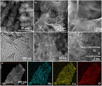 | ||
| Fig. 2 FE-SEM images of (a) CoMoO4 and (b and c) Co/MoO2, (d–f) TEM image of Co/MoO2, and (g) elemental maps of Co/MoO2. | ||
To determine the phase constituents, CoMoO4 and Co/MoO2 are analyzed by XRD. Fig. 3a exhibits diffraction peaks at 25.5°, 33.7°, 59.9°, 61.9°, and 63.1° corresponding to CoMoO4 (JCPDS No. 21-0868) (ref. 21) and new phases of MoO2 (JCPDS NO. 78-1070) (ref. 22) and metallic cobalt (JCPDS No. 15-0806) (ref. 23) are formed after reduction at 550 °C for 2 h in Ar/H2. The results demonstrate that the CoMoO4 precursor is reduced in Ar/H2 to generate Co and MoO2.
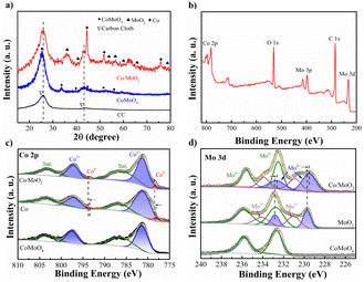 | ||
| Fig. 3 (a) XRD patterns of CC, CoMoO4 and Co/MoO2, (b) XPS spectrum of Co/MoO2, and high-resolution XPS spectra of (c) Co 2p and (d) Mo 3d of CoMoO4, Co/MoO2, MoO2 and Co. | ||
The change in the chemical states after phase separation is monitored by X-ray photoelectron spectroscopy (XPS). As shown in Fig. 3b, Co/MoO2 exhibits peaks of Co, Mo, O, and C. The fine spectrum of Co 2p of CoMoO4 in Fig. 3c can be fitted with peaks at 781.3 (Co2+ 2p3/2), 797.2 (Co2+ 2p1/2), 785.1, and 802.8 eV corresponding to the cobalt oxide Co(II) and satellite peaks,24 respectively. The metallic Co peaks of Co/MoO2 at 778.5 eV (Co0 2p3/2) and 793.5 eV (Co0 2p1/2)25 confirm that cobalt is formed in the phase separation process. It can be seen that the Co 2p spectra of Co/MoO2 varied to a higher binding energy than Co, manifesting the electrons depletion region on the sample of Co. Fig. 3d shows two peaks at 232.6 eV and 235.8 eV in the Mo 3d XPS spectrum associated with Mo 3d5/2 and Mo 3d3/2 of the Mo6+ state of CoMoO4.26 With regard to the reduced sample, the peaks at 229.5, 232.6, 230.8, 233.8, 232.5, and 235.5 eV are ascribed to the intermediate states of Mo4+, Mo5+ and Mo6+, further confirming the formation of MoO2.27–31 As shown in the graph, the Mo 3d spectra of Co/MoO2 transferred to a lower binding energy as contrasted with the sample of MoO2, which demonstrate the electrons accumulation on the MoO2. Thus, the electrons transfer from Co to MoO2.
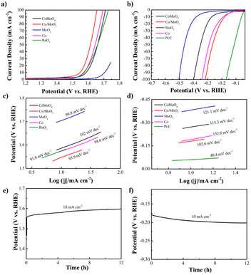
The electrocatalytic OER and HER characteristics are determined by LSV at a scan rate of 5 mV s−1 using a three-electrode configuration in N2-saturated 1 M KOH. A low overpotential (η) and small Tafel slope reflect high electrocatalytic activity in OER and HER at the desired large current density. For comparison Co, MoO2, RuO2 and Pt/C catalysts are also studied. Fig. 4a and c present the OER polarization and corresponding Tafel plots of the samples. The OER overpotential (η10) of Co/MoO2 is 318 mV, which is better than those of CoMoO4 (355 mV), RuO2 (345 mV), Co (343 mV) and MoO2 (470 mV). It is due to better electron transfer from Co to MoO2 at the Co/MoO2 interface consequently enriching the positive charges on the Co surface and simultaneously reducing the adsorption capacity of Co particles to oxygen species at the interface, resulting in enhanced oxygen evolution activity.32 Therefore, the Co/MoO2 composite is beneficial to the interfacial structure to enhance the intrinsic activity. Co and MoO2 promote oxygen evolution in alkaline solutions. Moreover, η10 of Co/MoO2 is better than those of previously reported catalysts such as MoO2/NF (350 mV),33 MoO2+OH− (435 mV),34 MoO2–Co (378 mV),35 MoO2–Co2Mo3O8@C (320 mV),36 Co2N0.67-BHPC (340 mV),37 Co/β-Mo2C@N-CNTs (356 mV)38 (Table S1†). The corresponding Tafel slope of Co/MoO2 is 93.9 mV dec−1, which is smaller than those of CoMoO4 (102 mV dec−1), Co (98.6 mV dec−1), and MoO2 (99.8 mV dec−1). Hence, Co/MoO2 has a smaller η10 and Tafel slope on account of the synergistic effects rendered by the individual heterostructures such as rapid desorption of gas and maintenance of active sites during gas generation.13 Electron transfer between Co and MoO2 enhances the electron donating ability and the bonding force between the transition metal Co and OH− increases to improve the OER performance.29 In addition, metallic cobalt enhances the oxygen evolution kinetics of Co/MoO2 by promoting the conductivity and accelerating transfer of electrons. Therefore, Co/MoO2 prepared by phase separation boosts the oxygen evolution capability.
The electrocatalytic HER properties are determined by LSV is shown in Fig. 4b and d. Co/MoO2 shows a smaller η10 of 178 mV compared to CoMoO4 (272 mV), Co (192 mV), and MoO2 (380 mV). For comparison, the Pt/C catalyst has a η10 of 59 mV in 1 M KOH. The HER properties of Co/MoO2 are better than of recently reported catalysts including MoO2 (200 mV),39 MoO2/NF (187 mV),33 Co@β-Mo2C-NC-0.115 (188 mV),40 MoO2–Co (422 mV),35 Co–CoO/BC (210 mV),41 Mo2C/MoO2 (204 mV)42 (Table S2†). The HER reaction involves two stages.43 The first steep is the Volmer reaction with a Tafel slope of about 118 mV dec−1 and the second one is the Heyrovsky reaction with a Tafel slope of approximately 39 mV dec−1 or Tafel reaction with a Tafel slope of 29 mV dec−1. The HER Tafel slope of Co/MoO2 is 102.6 mV dec−1 indicative of the Volmer–Heyrovsky mechanism. The hydrogen evolution reaction requires a large number of protons which in an alkaline solution originate from dissociation of water. Therefore, the hydrogen evolution rate of Co/MoO2 in the alkaline solution is governed by the Volmer reaction. The Tafel slope of Co/MoO2 is smaller than those of CoMoO4 (115.3 mV dec−1), Co (132.6 mV dec−1), and MoO2 (121.1 mV dec−1). Metallic cobalt provides the H* adsorption sites to promote water dissociation and improving the Co/MoO2 HER properties.44 Furthermore, Mo–H has a strong adsorption energy which inhibits desorption. The electronic structure of Mo is regulated by the transition metal Co, which diminishes the Mo–H binding energy and makes it easier to desorb. Consequently, hydrogen evolution from Co/MoO2 is further improved.13 When Co/MoO2 transfers electrons from Co to MoO2, the Co surface is enriched with positive charges and the Co particles near the interface decreases the ability to adsorb hydrogen to enhance hydrogen evolution.45 Therefore, the Co/MoO2 heterojunction improves the intrinsic activity of Co and MoO2 synergistically in the alkaline solution. Galvanostatic tests are performed on the Co/MoO2 catalyst for both OER and HER as shown in Fig. 4e and f further revealing the stability in the electrochemical reaction.
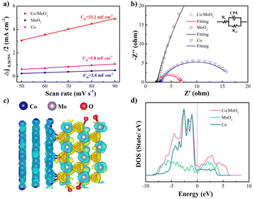
The electrochemical active surface area (ECSA) is another critical parameter for the catalytic activity and characterized by the electrochemical double layer capacitance (Cdl). Cyclic voltammetry (CV) is performed at different scanning rates in the non-Faraday current interval (Fig. S2†). The electric double layer capacitance is related to the number of active sites in the electrochemical reaction46 and CV is utilized to determine the number of active sites. As shown in Fig. 5a, the Cdl value of Co/MoO2 (23.2 mF cm−2) is bigger than those of MoO2 (3.4 mF cm−2) and Co (5.8 mF cm−2), implying that the Co/MoO2 catalyst has more active sites. Electrochemical impedance spectroscopy (EIS) is employed to study the interfacial dynamics and as shown in the equivalent series model composed of the solution resistance Rs (intersection between the high frequency region and X-axis), CPE (constant phase angle element), and parallel Rct, the faster charge transfer and transmission, the smaller is the diameter of the semi-circular Rct. Fig. 5b shows smaller Rct than others (Fig. S3†) because that in situ formation of Co/MoO2 reduces the interface resistance and raises the charge conduction rate thus exploiting the synergetic effects rendered by Co and MoO2. The calculated differential charge density in Fig. 5c illustrates that the charge density redistributes at the interface showing an electron accumulation region (yellow region) on the MoO2 side and electron loss region (blue region) on the Co side, indicating electron transfer from Co to MoO2. The density of states (DOS) in Fig. 5d reveals that the state of Co/MoO2 is located at the Fermi level higher than MoO2 and Co, thereby explaining why Co/MoO2 improves the electron activity as consistent with the Fig. 5b.
Co/MoO2 catalysts are prepared at different temperature and the HER and OER characteristics are evaluated by LSV to assess the influence of the catalyst configuration and composition on the electrochemical properties (Fig. S4†). Owing to the proper structure, Co/MoO2 prepared at 550 °C delivers better electrocatalytic performance than other samples. As shown in Fig. S5 and S6,† when the temperature is 450 °C, the nanosheets are still CoMoO4 and no particles are deposited on the nanosheets. However, at 650 °C, the morphology changes into a porous network because of the formation of the new phase of Co3Mo (JCPDS NO. 29-0488).13
The Co/MoO2 catalysts are assembled as the anode and cathode to conduct overall water splitting in 1 M KOH. The cell voltage is 1.72 V at a current density of 10 mA cm−2, which is competitive to the other non-noble metal bifunctional catalysts reported in the literature, including Co@β-Mo2C-NC-0.115 (1.72 V),40 Co2P/Mo2C/Mo3Co3C@C (1.74 V),47 Co–CoO/BC (1.77 V),41 P–MoO2 (1.83 V),48 NiO/NiFe2O4 (1.82 V)49 (Table S3†). The overall water splitting potential of the Co/MoO2-based electrolyzer rises slightly after continuous operation for 12 h in the alkaline solution (Fig. 6).
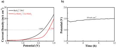 | ||
| Fig. 6 (a) Water splitting LSV curves of Co/MoO2 as both the cathode and anode and (b) Co/MoO2 water splitting electrolyzer galvanostatic test for 12 h at 10 mA cm−2. | ||
4 Conclusions
A Co/MoO2 catalyst is fabricated by a one-step phase separation process of CoMoO4 in the Ar/H2 atmosphere. The in situ generated metallic Co nanoparticles on the MoO2 nanosheets improve the HER characteristics of MoO2, whereas the MoO2 nanosheets impede agglomeration of nanosized Co in OER. The Co/MoO2 composite shows superior HER and OER properties compared to single-phase catalysts of Co and MoO2. In the alkaline solution, the η10 values of Co/MoO2 for HER and OER are 178 and 318 mV, respectively. The electrolytic cell assembled with the bifunctional Co/MoO2 electrocatalyst shows a low voltage of 1.72 V for a current density of 10 mA cm−2 in overall water splitting. The in situ separation strategy to form the transition metal and oxide heterojunction has large potential in designing non-noble metal catalysts for electrocatalytic water splitting and other applications.Author contributions
LX implemented the experiment, analyzed the data and wrote the article. YL, HS, XL, WG, XJ, MJ and XZ participated in the formulation of the experimental scheme. BG and PC revised the article.Conflicts of interest
There are no conflicts to declare.Acknowledgements
This work was financially supported by the College Student Innovation and Entrepreneurship Training Program of Hubei Province (S202110488013), Hubei Key Laboratory for Efficient Utilization and Agglomeration of Metallurgic Mineral Resources Open Project Fund (2019zy004), Foundation of Science Research Program from the Hubei Provincial Department of Education (No. Q20221101), Hubei Province Natural Science Foundation Innovation Group Project (2019CFA020), Young Top-notch Talent Cultivation Program of Hubei Province and Outstanding Youth Foundation of Natural Science Foundation of Hubei Province (2020CFA099), City University of Hong Kong Donation Research Grant (DON-RMG 9229021), City University of Hong Kong Donation Grant (9220061), Hong Kong ITC (Innovation and Technology Commission) ITF (Innovation and Technology Fund) (GHP/149/20SZ and CityU 9440296), as well as Shenzhen-Hong Kong Innovative Collaborative Research and Development Program (SGLH20181109110802117 and CityU 9240014). Thank the Analysis and Testing Center of Wuhan University of Science and Technology for analytical support.Notes and references
- W. J. Jiang, T. Tang, Y. Zhang and J. S. Hu, Acc. Chem. Res., 2020, 53, 1111–1123 CrossRef CAS PubMed.
- Z. Zheng, L. Yu, M. Gao, X. Chen, W. Zhou, C. Ma, L. Wu, J. Zhu, X. Meng, J. Hu, Y. Tu, S. Wu, J. Mao, Z. Tian and D. Deng, Nat. Commun., 2020, 11, 3315 CrossRef CAS PubMed.
- Y. Chen, Y. Wang, J. Yu, G. Xiong, H. Niu, Y. Li, D. Sun, X. Zhang, H. Liu and W. Zhou, Adv. Sci., 2022, 9, 2105869 CrossRef CAS.
- X. Zou and Y. Zhang, Chem. Soc. Rev., 2015, 44, 5148–5180 RSC.
- N. T. Suen, S. F. Hung, Q. Quan, N. Zhang, Y. J. Xu and H. M. Chen, Chem. Soc. Rev., 2017, 46, 337–365 RSC.
- B. Chang, J. Yang, Y. Shao, L. Zhang, W. Fan, B. Huang, Y. Wu and X. Hao, ChemSusChem, 2018, 11, 3198–3207 CrossRef CAS.
- X. Xie, L. Lin, R. Y. Liu, Y. F. Jiang, Q. Zhu and A. W. Xu, J. Mater. Chem. A, 2015, 3, 8055–8061 RSC.
- J. Guo, J. Wang, Z. Wu, W. Lei, J. Zhu, K. Xia and D. Wang, J. Mater. Chem. A, 2017, 5, 4879–4885 RSC.
- L. Wu, X. Wang, Y. Sun, Y. Liu and J. Li, Nanoscale, 2015, 7, 7040–7044 RSC.
- Y. Jin, H. Wang, J. Li, X. Yue, Y. Han, P. K. Shen and Y. Cui, Adv. Mater., 2016, 28, 3785–3790 CrossRef CAS.
- Y. Jin and P. K. Shen, J. Mater. Chem. A, 2015, 3, 20080–20085 RSC.
- X. Zhang, F. Zhou, W. Pan, Y. Liang and R. Wang, Adv. Funct. Mater., 2018, 28, 1804600 CrossRef.
- J. Chen, Y. Ge, Q. Feng, P. Zhuang, H. Chu, Y. Cao, W. R. Smith, P. Dong, M. Ye and J. Shen, ACS Appl. Mater. Interfaces, 2019, 11, 9002–9010 CrossRef CAS PubMed.
- Z. Chen, X. Duan, W. Wei, S. Wang and B. J. Ni, J. Mater. Chem. A, 2019, 7, 14971–15005 RSC.
- X. Yan, L. Tian, S. Atkins, Y. Liu, J. Murowchick and X. B. Chen, ACS Sustainable Chem. Eng., 2016, 7, 3743–3749 CrossRef.
- M. Gong, W. Zhou, M. C. Tsai, J. Zhou, M. Guan, M. C. Lin, B. Zhang, Y. Hu, D. Y. Wang, J. Yang, S. J. Pennycook, B. J. Hwang and H. Dai, Nat. Commun., 2014, 5, 4695 CrossRef CAS PubMed.
- G. Liu, H. Bai, Y. Ji, L. Wang, Y. Wen, H. Lin, L. Zheng, Y. Li, B. Zhang and H. Peng, J. Mater. Chem. A, 2019, 7, 12434–12439 RSC.
- X. Liu, K. Ni, C. Niu, R. Guo, W. Xi, Z. Wang, J. Meng, J. Li, Y. Zhu, P. Wu, Q. Li, J. Luo, X. Wu and L. Mai, ACS Catal., 2019, 9, 2275–2285 CrossRef CAS.
- H. Zhao, Z. Li, X. Dai, M. Cui, F. Nie, X. Zhang, Z. Ren, Z. Yang, Y. Gan, X. Yin, Y. Wang and W. Song, J. Mater. Chem. A, 2020, 8, 6732–6739 RSC.
- X. Yang, A. Y. Lu, Y. Zhu, M. N. Hedhili, S. Min, K. W. Huang, Y. Han and L. J. Li, Nano Energy, 2015, 15, 634–641 CrossRef CAS.
- K. Wu, J. Zhan, G. Xu, C. Zhang, D. Pan and M. Wu, Nanoscale, 2018, 10, 16040–16049 RSC.
- X. F. Lu, Y. Chen, S. Wang, S. Gao and X. W. Lou, Adv. Mater., 2019, 31, 1902339 CrossRef.
- L. X. Song, M. Wang, S. Z. Pan, J. Yang, J. Chen and J. Yang, J. Mater. Chem., 2011, 21, 7982–7989 RSC.
- J. Jiang, Q. Liu, C. Zeng and L. Ai, J. Mater. Chem. A, 2017, 5, 16929–16935 RSC.
- X. Lang, M. A. Qadeer, G. Shen, R. Zhang, S. Yang, J. An, L. Pan and J. J. Zou, J. Mater. Chem. A, 2019, 7, 20579–20583 RSC.
- H. Jiang, Z. Cui, C. Xu and W. Li, Chem. Commun., 2019, 55, 9432–9435 RSC.
- X. Shi, A. Wu, H. Yan, L. Zhang, C. Tian, L. Wang and H. Fu, J. Mater. Chem. A, 2018, 6, 20100–20109 RSC.
- Y. Lu, H. Ang, Q. Yan and E. Fong, Chem. Mater., 2016, 28, 5743–5752 CrossRef CAS.
- N. K. Oh, C. Kim, J. Lee, O. Kwon, Y. Choi, G. Y. Jung, H. Y. Lim, S. K. Kwak, G. Kim and H. Park, Nat. Commun., 2019, 10, 1723 CrossRef PubMed.
- C. Li, H. Jang, M. G. Kim, L. Hou, X. Liu and J. Cho, Appl. Catal., B, 2022, 307, 121204 CrossRef CAS.
- H. Guo, A. Wu, Y. Xie, H. Yan, D. Wang, L. Wang and C. Tian, J. Mater. Chem. A, 2021, 9, 8620–8629 RSC.
- C. Liu, K. Wang, X. Zheng, X. Liu, Q. Liang and Z. Chen, Carbon, 2018, 139, 1–9 CrossRef CAS.
- Y. Sun, Y. Zhou, Y. Zhu, Y. Shen and A. Xie, ACS Sustainable Chem. Eng., 2019, 7, 9153–9163 CrossRef CAS.
- P. Guha, B. Mohanty, R. Thapa, R. M. Kadam, P. V. Satyam and B. K. Jena, ACS Appl. Energy Mater., 2020, 3, 5208–5218 CrossRef CAS.
- Y. Li, C. Wang, M. Cui, J. Xiong, L. Mi and S. Chen, Appl. Surf. Sci., 2021, 543, 148804 CrossRef CAS.
- Y. Li, H. Xu, H. Huang, C. Wang, L. Gao and T. Ma, Chem. Commun., 2018, 54, 2739–2742 RSC.
- X. Lv, Z. Xiao, H. Wang, X. Wang, L. Shan, F. Wang, C. Wei, X. Tang and Y. Chen, J. Energy Chem., 2021, 54, 626–638 CrossRef CAS.
- T. Ouyang, Y.-Q. Ye, C.-Y. Wu, K. Xiao and Z.-Q. Liu, Angew. Chem., Int. Ed., 2019, 58, 4923–4928 CrossRef CAS PubMed.
- B. Wang, Z. Zhang, S. Zhang, Y. Cao, Y. Su, S. Liu, W. Tang, J. Yu, Y. Ou, S. Xie, J. Li and M. Ma, Electrochim. Acta, 2020, 359, 136929 CrossRef CAS.
- U. Ali, Y. Yu, J. Guo, Y. Liu, Z. Mu and S. Xing, J. Electrochem. Soc., 2020, 167, 044520 CrossRef CAS.
- M. Yang, D. Wu and D. Cheng, Int. J. Hydrogen Energy, 2019, 44, 6525–6534 CrossRef CAS.
- M. Liu, Y. Yang, X. Luan, X. Dai, X. Zhang, J. Yong, H. Qiao, H. Zhao, W. Song and X. Huang, ACS Sustainable Chem. Eng., 2018, 6, 14356–14364 CrossRef CAS.
- Y. Shi and B. Zhang, Chem. Soc. Rev., 2016, 45, 1529–1541 RSC.
- G. Cai, W. Zhang, L. Jiao, S. H. Yu and H. L. Jiang, Chem, 2017, 2, 791–802 CAS.
- X. Yan, L. Tian, M. He and X. Chen, Nano Lett., 2015, 15, 6015–6021 CrossRef CAS PubMed.
- Z. H. Deng, L. Li, W. Ding, K. Xiong and Z. D. Wei, Chem. Commun., 2015, 51, 1893–1896 RSC.
- X. Li, X. Wang, J. Zhou, L. Han, C. Sun, Q. Wang and Z. Su, J. Mater. Chem. A, 2018, 6, 5789–5796 RSC.
- Z. Cui, T. Feng, X. Wang, P. Guo, W. Wang, M. E. Yue and Z. Li, Fuel, 2023, 332, 126250 CrossRef CAS.
- H. Zhong, G. Gao, X. Wang, H. Wu, S. Shen, W. Zuo, G. Cai, G. Wei, Y. Shi, D. Fu, C. Jiang, L. W. Wang and F. Ren, Small, 2021, 17, 2103501 CrossRef CAS PubMed.
Footnote |
| † Electronic supplementary information (ESI) available. See DOI: https://doi.org/10.1039/d2ra06117a |
| This journal is © The Royal Society of Chemistry 2022 |


