
 Open Access Article
 This Open Access Article is licensed under a Creative Commons Attribution-Non Commercial 3.0 Unported Licence
Evidence of a reversible redox reaction in a liquid-electrolyte-type fluoride-ion battery†
Ritsuko Yaokawa *,
Tohru Shiga,
Shinya Moribe and
Kazuhiko Mukai
*,
Tohru Shiga,
Shinya Moribe and
Kazuhiko Mukai
Toyota Central Research & Development Laboratories, Inc., Yokomichi 41–1, Nagakute, Aichi 480–1192, Japan. E-mail: e4777@mosk.tytlabs.co.jp
First published on 7th November 2022
Abstract
Fluoride-ion batteries (FIBs) have received significant attention as promising alternatives to conventional lithium-ion batteries, but a reversible redox reaction has not been confirmed yet for liquid-electrolyte-type FIBs. We conducted ex situ X-ray diffraction and energy dispersive X-ray analyses for a conventional full-cell assembly of FIBs, in which BiF3, a Pb plate (or Pb powder), and tetraethylammonium fluoride dissolved in propylene carbonate were used as the positive electrode, negative electrode, and liquid electrolyte, respectively. A FIB using a Pb plate exhibited a flat operating voltage at ∼0.29 V during the discharge reaction with a discharge capacity of ∼105 mA h g−1. The reversible electrochemical reaction was, however, attained when the discharge and charge capacities were controlled to be less than 20 mA h g−1. In a such capacity-limited cycle test, Bi and PbF2 phases were formed during the discharge reaction, while BiF3 and Pb phases were generated during the charge reaction. Therefore, a reversible movement of F− ions between the BiF3 and Pb electrodes, i.e., reversible redox reaction was firstly confirmed for the liquid-electrolyte-type FIB. We also attempted to improve the reversibility at the first cycle by replacing the Pb plate with Pb powder electrodes, and consequently, the FIB using an annealed Pb powder indicated the best electrochemical performance.
Introduction
Lithium-ion batteries (LIBs) are based on a reversible reaction wherein Li+ ions move back and forth between positive and negative electrodes while maintaining each core structure, i.e., a topotactic reaction.1 This topotactic reaction enables LIBs to cycle more than several thousand times but restricts their maximum volumetric energy density (Wvol ≅ 1000 W h L−1), hindering their widespread application, particularly in devices requiring a high energy density, such as stationary energy storage systems.2 Recently, fluoride-ion batteries (FIBs) have received considerable attention for moving beyond LIBs because the Wvol of FIBs has been reported to reach ∼5000 W h L−1 owing to their wide operating voltage (>5 V) and multivalent redox reactions.3–7Despite these high expectations, many issues must be overcome to realize practical FIBs. Solid-state F− conductors are employed as the electrolyte rather than liquid solutions to avoid the difficulties involved in preparing liquid electrolytes and to stabilize the redox reactions.8–13 In recent years, solid electrolytes with high ionic conductivity have improved the room-temperature performance of solid-state FIBs,11–15 but all-solid-state FIBs usually require high operating temperatures above 150 °C,8–10 resulting in several drawbacks, e.g., high cost and limited use. Many researchers have thus endeavored to replace solid electrolytes with liquid ones.16–26 Most of these studies evaluated redox reactions in a half-cell with respect to a certain reference electrode.
To our best knowledge, only two studies on a beaker-type full-cell consisting of both positive and negative electrodes have been made by Abe and co-workers.16,17 The first study is based on a Bi|MPPF + TMPA-TFSA|PbF2-deposited Pb cell, where MPPF and TMPA-TFSA represent 1-methyl-1-propylpiperidinium fluoride and N,N,N-trimethyl-N-propylammonium bis(trifluoromethanesulfonyl)amide, respectively.16 Approximately 0.3 and 0.17 mA h of charge and discharge capacities (Qcha and Qdis) are obtained at 25 °C, but there is no information about gravimetric Qcha and Qdis.16 The gravimetric values of Qcha ≅ 190 mA h g−1 and Qdis ≅ 260 mA h g−1 are provided on the second study in a BiF3|KHF2/propylene carbonate (PC)|Pb cell, for which the discharge cut-off voltage is expanded to −0.1 V vs. Pb2+/Pb.17 Ex situ X-ray diffraction (XRD) and X-ray photoelectron spectroscopy were measured only for the positive electrode, to conclude the redox reactions between the two electrodes.16,17
The question then arises whether F− ions move back and forth between the BiF3 (positive) and Pb (negative) phases through the liquid-electrolytes. This is because a large amount of the liquid electrolytes in the beaker-type full-cell can supply F− ions to both electrodes. Furthermore, electrode materials in FIBs easily dissolve into liquid-electrolytes during the discharge and charge reactions,17,19,25,26 adding to Qcha and Qdis as an extra electric charge. In this sense, a reversible movement of F− ions between the two electrodes, i.e., reversible redox reaction as that for LIBs, has not been confirmed yet for liquid-electrolyte-type FIBs. Another drawback using the beaker-type full-cell is to diminish the Wvol of FIBs, which is one of motivations for pursuing FIBs.
Considering above situation, it is crucial to confirm that a reversible redox reaction occurs in FIBs in a conventional (full-) cell assembly as it does in LIBs.1,2 This task is essential for further developments and implementation of FIBs, although such a fundamental approach for establishing FIB chemistry seems to have been overlooked in previous FIB studies.16–26 Therefore, in this study, we fabricated an FIB using a hermetically sealed cell that has been utilized in LIB studies (Fig. S1†). We then examined structural and compositional variations in the electrodes for both positive and negative electrodes by ex situ XRD and energy dispersive X-ray (EDX) analyses. BiF3 and Pb, the most representative electrodes for which redox reactions have been confirmed in half-cells, were selected as positive and negative electrodes.18–26 We also chose 0.1 M tetraethylammonium fluoride (TEAF) dissolved in PC as a liquid electrolyte (TEAF/PC). TEAF is composed of tetraalkylammonium cations and has a molecular structure similar to those of other previously investigated fluoride salts, such as tetramethylammonium fluoride (TMAF).19 Consequently, we found that the movement of F− ions between the BF3 and Pb electrodes through the TEAF/PC electrolyte is reversible.
Experimental
The positive electrode consisted of 80 wt% BiF3 powder (Sigma-Aldrich), 10 wt% carbon black (CB, TB5500; Tokai Carbon), and 10 wt% polytetrafluoroethylene (PTFE, F-104; Daikin). For the negative electrode, we used three different types of Pb: Pb plate (Pb-plate, Nilaco), as-received Pb powder (rcv-Pb, Kojyundo Chemical Laboratory), and annealed Pb powder (a-Pb). To prepare a-Pb, rcv-Pb was heated at 150 °C for 1 h in a high-frequency induction heating furnace equipped with an Ar-filled glovebox. The Pb-plate was used by itself as a negative electrode. Two negative electrodes were also prepared from powders, and each consisted of a mixture of 80 wt% rcv-Pb (or a-Pb), 10 wt% CB, and 10 wt% PTFE. The diameters of the positive and negative electrodes were 14 and 16 mm, respectively, and all three electrodes were 200 μm thick. TMAF and TEAF were provided by Sigma-Aldrich; however, we used only TEAF because TMAF was difficult to dissolve into PC (Kishida Chemical). To clarify the voltage window of the TEAF/PC electrolyte (0.1 M), linear sweep voltammetry (LSV, IVIUMSTAT; Hokuto Denko) was conducted at a scan rate of 1 mV s−1 and 25 °C using Pt electrodes.Fig. S1† shows photographs and the schematic structure of the hermetically sealed cell. This two-electrode-type cell is typical for LIBs,27 but as far as we concerned, it has never been used for liquid-electrolyte-type FIBs. A porous polyethylene film with a thickness of 25 μm (E25MMS; Tonen Chemical) was inserted between the positive (60–100 mg) and negative (480 mg for the Pb plate and 80 mg for the rcv-Pb and a-Pb powders) electrodes, along with 200 μL of the electrolyte. The amount of the TEAF/PC electrolyte per milligram of electrode materials was calculated to be 0.34–1.4 μL mg−1, which is similar to that (= 0.5–1.0 μL mg−1) of commercial LIBs.28 After being assembled in the Ar-filled glovebox, the cells were operated with a current of 0.02 mA (∼13 μA cm−2) at 25 °C in the range of 0.1–1.2 (or 0.0–1.1 V). We also performed capacity (Q)-limited cycling tests up to a Q of 10, 20 and 30 mA h g−1.
Ex situ XRD was conducted with a Cu-Ka radiation in the range of 2θ = 10–70°. The lattice parameters were determined by the Cohen method29 using at least five diffraction lines. The morphologies and compositions were investigated by scanning electron microscopy (SEM; SU3500, Hitachi High-Technologies) and EDX analyses.
Results and discussion
According to the LSV curve shown in Fig. S2,† the voltage window of the TEAF/PC electrolyte was approximately −1 V to +1 V between the Pt electrodes, which is enough for examining electrochemical reactivities of FIBs. Fig. 1(a) shows the discharge and charge curves of the BiF3|TEAF/PC|Pb-plate cell. The specific Q in the horizontal axis was calculated based on the weight of the BiF3 sample. The open-circuit voltage was 1.07 V in the freshly fabricated state (= initial state, I). The cell voltage (E) rapidly dropped to ∼0.18 V at the beginning of the discharge reaction and then reached a voltage plateau at ∼0.29 V, which was higher and flatter than those in previous studies.16,17 This flat E is characteristic of a two-phase reaction in which E does not obey a simple Nernst equation.30 Specifically, the discharge reaction can be represented as| BiF3 + 3xe− → (1 − x)BiF3 + xBi + 3xF− | (1) |
| 3/2Pb + 3xF−→3/2(1 − x)Pb + 3x/2PbF2 + 3xe− | (2) |
 | ||
| Fig. 1 (a) Discharge and charge curves of the BiF3|TEAF/PC|Pb-plate cell. Ex situ XRD patterns recorded from the (b) BiF3 and (c) Pb-plate electrodes at various states in (a): initial (I), discharged to 0.1 V (D), and charged to 1.2 V (C). Cross-sectional (d) BSE image and EDX mappings showing (e) Pb and (f) F in the Pb-plate electrode at D. (g) BSE image of the surface of the Pb-plate electrode at D. EDX spectra from areas (h) A and (i) B in (g). | ||
Because a Qdis of ∼105 mA h g−1 was obtained at the first cycle, the value of x was calculated to be ∼0.35 based on the theoretical Q described in eqn (1) (= 302.3 mA h g−1). However, the subsequent Qcha was less than 10 mA h g−1 [Fig. 1(a)]. This extremely irreversible redox reaction can also be understood by the unchanged XRD pattern in the charge state at 1.2 V (C) [Fig. 1(c)]. The origins of this irreversibility are currently unclear, but SEM-EDX analyses at D reveal an inhomogeneous distribution of F− ions and the dissolution of Bi3+ ions into the TEAF/PC electrolyte [Fig. 1(d)–(i)]. According to the back-scattered electron (BSE) images and EDX spectra illustrated in Fig. 1(d)–(f), F atoms penetrate to a depth of ∼70 μm, but they are inhomogeneously distributed on the surface. Furthermore, Bi atoms appear in area B at a Pb/Bi ratio of 0.9/0.1, indicating the dissolution of Bi3+ ions and decomposition of the TEAF/PC electrolyte. Such an inhomogeneous distribution of F− ions and the existence of metallic Bi (and/or PbyBi1–y) unavoidably decrease the reversibility of the redox reaction. In contrast to that in a beaker-type cell, which contains an excess of electrolyte,16–26 the electrolyte decomposition in the hermetically sealed cell severely degrades the reversibility of the redox reaction. Fig. 1(c) presents the XRD patterns recorded at points D and C in Fig. 1(a), which confirm the existence of metallic Bi and PbyBi1−y in the Pb-plate electrode, although the y value is estimated to be 0.7 from the diffraction angle of ∼33.4°.33
To suppress the electrolyte decomposition and the formation of metallic Bi and PbyBi1−y, we performed Q-limited cycling tests, as shown in Fig. 2(a). One plateau at ∼0.27 V appeared during the discharge reaction, and two plateaus occurred at ∼0.37 and 0.96 V during the charge reaction. Steady cycling performance appeared at Q = 10 mA h g−1, except for the increase in E at the end of the charge reaction. This increase in E is originated from the distribution and thickness of the PbF2 phase, as discussed later. Fig. 2(b) shows the ex situ XRD patterns of the BiF3 electrode at Qdis = 10 mA h g−1 [D(10)] and Qcha = 10 mA h g−1 [C(10)], and Fig. S4(a)† shows their full-2θ range XRD patterns. Diffraction lines from the Bi phase are observed at ∼27.2°, 38.2°, and 39.8° at D(10), whereas these diffraction lines have almost disappeared at C(10), indicating the reversible reaction of eqn (1) [Fig. 2(b)]. The diffraction lines from the o-BiF3 phase are weakened at D(10), indicating the preferential reduction of the o-BiF3 phase above ∼0.2 V.
 | ||
| Fig. 2 (a) Q-limited discharge and charge curves of the BiF3|TEAF/PC|Pb-plate cell when Q = 10 mA h g−1. Ex situ XRD patterns recorded from the (b) BiF3 and (c) Pb-plate electrodes at various states in (a): initial (I), Qdis = 10 mA h g−1 [D(10)], and Qcha = 10 mA h g−1 [C(10)]. | ||
For the Q-limited cycle test, the reversible reaction of eqn (2) was verified by the ex situ XRD patterns of the Pb-plate electrode, as shown in Fig. 2(c) and S4(b).† The diffraction lines from metallic Bi and PbyBi1−y are barely observed at either D(10) or C(10), whereas those from the PbF2 phase appear at ∼26.0°, 30.1°, and 43.1°. Table S2† summarizes the lattice parameters of the BiF3, Bi, Pb, and PbF2 phases. Evidently, the Pb(111)/PbF2(111) ratio increases from 0.24 at D(10) to 0.39 at C(10), where diffraction lines for the Pb(111) and PbF2(111) planes occur at 31.3° and 26.0°, respectively (Fig. S5†). Moreover, BSE image at D(10) indicates a formation of PbF2 phase on the Pb plate, while SEM-EDX analyses at C(10) confirm the defluorination of PbF2 on the surface (Fig. S6 and S7†). These results indicate that Pb was oxidized to PbF2 during discharging and then PbF2 was reduced to Pb during charging. Hence, combining eqn (1) and (2), the overall redox reaction of the BiF3|TEAF/PC|Pb-plate cell can be described by
| BiF3 + 3/2Pb ↔ (1 − x)BiF3 + xBi + 3/2(1 − x)Pb + 3x/2PbF2 | (3) |
The Q values in the Q-limited cycle test were increased to 20 and 30 mA h g−1. As shown in Fig. S8(a),† steady cycling performance is also attained at Q = 20 mA h g−1, enlarging the reversible x value in eqn (3) by two times (≅ 0.066). However, at Q = 30 mA h g−1, E rapidly drops to ∼0.6 V from above 1 V during the charge reaction, indicating the presence of other side reactions [Fig. S8(b)†]. Besides the dissolution of electrodes17,19,25,26 and/or decomposition of liquid electrolytes that have been pointed out for FIBs, the distribution and thickness of the PbF2 phase are thought to affect the reduction to Pb at above 1 V. As understood by the BSE images, the PbF2 layer with a thickness of ∼70 μm covered with the Pb plate [Fig. 1(f)], while the non-uniformed PbF2 islands with a size of ∼30 μm partially locates on the Pb plate (Fig. S6†). The partial distribution and thin layer of the PbF2 phase maintain the electrical conduction between PbF2 and Pb (or current collector), offering reversible redox reactions.
Here, we wish to verify the redox reaction by comparing the magnitude of observed Q with the amount of the electrolyte used. Because 200 μL of the TEAF/PC electrolyte was injected into one full-cell, the amount of F− ions in the liquid electrolyte is calculated to be 2 × 10⁻⁵ mol, which can deliver to Q of ∼0.54 mA h if all the F− ions in eqn (2) are supplied by the liquid electrolyte. Because Q of 20 mA h g−1 corresponds to 1.56 mA h based on the weight of the BiF3 sample, the reversible movement of F− ions between the two electrodes, i.e., reversible redox reaction is confirmed.
As reported previously,7–26 the rechargeable Q values for liquid-electrolyte-type FIBs are somewhat lower than those for all-solid-state FIBs. In this study, Qcha at the first cycle was only ∼9 mA h g−1 when the discharge cut-off voltage was set to 0.1 V [Fig. 1(a)]. One strategy for raising Qcha is to increase the active surface area involved in the redox reaction. Konishi et al. demonstrated that compositing PbF2 and carbon via ball milling increased the specific Q of the resulting PbF2 electrodes.24 We thus replaced the Pb-plate with rcv-Pb or a-Pb as the negative electrode.
Fig. 3(a) shows the discharge and charge curves of the BiF3|TEAF/PC|rcv-Pb cell at the first cycle, where the average particle size of the rcv-Pb powder is ∼200 μm [Fig. S9(a)†]. The E during the discharge reaction is almost constant at ∼0.29 V until ∼100 mA h g−1, except for a drop to ∼0 V at Qdis < 10 mA h g−1. The Qdis and Qcha values reach 110 and 60 mA h g−1, respectively, yielding a high reversibility of ∼55% compared to that (≅ 0.09%) for the BiF3|TEAF/PC|Pb-plate cell. Note that it took approximately two (one) weeks to complete the discharge (charge) reaction, corresponding to C-rate of C/360 (C/180). This C-rate is significantly lower than those for previous FIB studies using solid-state electrolytes7 or liquid electrolytes,17 indicating that the cell was maintained under a severe condition for a long time. Fig. 3(b) and (c) show ex situ XRD patterns of the BiF3 and rcv-Pb electrodes, respectively, at I, discharged down to 0 V [D(rcv)] and charged up to 1.1 V [C(rcv)]. Bi and PbF2 phases are produced at D(rcv), but the diffraction lines from these phases are weakened at C(rcv). The o-BiF3 phase almost disappears at D(rcv) and never appear at C(rcv), as in the case for the BiF3|TEAF/PC|Pb-plate cell when E was discharged to 0.1 V. The Pb(111)/PbF2(111) ratio increases significantly from 0.06 at D(rcv) to 1.32 at C(rcv) (Fig. S10†), being consistent with the result that rcv-Pb indicates a higher reversibility than Pb plate. Additionally, the EDX mappings of Pb and F at C(rcv) reveal that the surface of the rcv-Pb powder is defluorinated during the charge reaction [Fig. S9(b) and (c)†].
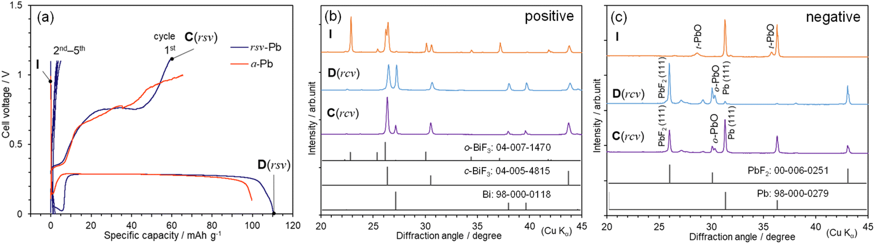 | ||
| Fig. 3 (a) Discharge and charge curves of the BiF3|TEAF/PC|rcv-Pb and BiF3|TEAF/PC|a-Pb cells. Ex situ XRD patterns recorded from the (b) BiF3 and (c) rcv-Pb electrodes in the BiF3|TEAF/PC|rcv-Pb cell at various states in (a): initial (I), discharged to 0 V [D(rcv)], and charged to 1.1 V [C(rcv)]. | ||
We performed an extended cycle test up to five cycles for the BiF3|TEAF/PC|rcv-Pb cell and illustrate corresponding discharge and charge curves in Fig. 3(a). The Qdis and Qcha values for the subsequent cycles rapidly decrease to ∼5 mA h g−1, indicating a similar cycle performance to the BiF3|TEAF/PC|Pb-plate cell, shown in Fig. 1(a). For the Bi|MPPF + TMPA-TFSA|PbF2-deposited Pb cell, Qdis decreases from 0.17 mA h to 0.01 mA h after five cycles.16 In contrast, FIBs using solid electrolytes exhibit a relatively stable cycle performance;7 for instance, Qdis of 50–60 mA h g−1 is maintained up to ten cycles for the BiF3|BaSnF4|Zn cell.34 These results indicate difficulties in the improvement of cycle performance of liquid-electrolyte-type FIBs. Further developments such as stabilization of liquid electrolytes are encouraged.
Finally, we attempted to diminish the drop in E at Qdis < 10 mA h g−1. As shown in Fig. 3(c), rcv-Pb contains a small amount of a tetragonal PbO (t-PbO) as an impurity at I, which transforms into an orthorhombic PbO (o-PbO) phase at D(rcv). Next, we prepared a cell using a-Pb, which was produced by annealing rcv-Pb under an Ar atmosphere, and we examined the discharge profile. As expected, the drop in E was mitigated for the BiF3|TEAF/PC|a-Pb cell, indicating the involvement of oxygen in the redox reaction [Fig. 3(a)]. The ex situ XRD pattern after the first cycle (Fig. S11†) also confirms the absence of the PbO phases.
Conclusions
We examined reaction mechanisms for three types of BiF3|TEAF/PC|Pb cell via ex situ XRD and EDX analyses. The BiF3|TEAF/PC|Pb-plate cell exhibited a flat operating voltage at ∼0.29 V during the discharge reaction with a Qdis of 105 mA h g−1. The electrochemical reaction was reversible in the Q-limited cycle test less than 20 mA h g−1. The Bi and PbF2 phases were formed at D(10), while the Pb(111)/PbF2(111) ratio increased to 0.39 at C(10). Combining the SEM-EDX results at D(10) and C(10), we confirmed the reversible movement of F− ions between the BiF3 and Pb electrodes, i.e., redox rection in the liquid-electrolyte-type FIB. We also successfully improved the reversibility of the redox reaction at the first cycle by replacing the Pb plate with rcv-Pb or a-Pb powder. Specifically, approximately ∼55% of the reversibility was attained for the BiF3|TEAF/PC|rcv-Pb cell, while the drop in E at Qdis < 10 mA h g−1 was mitigated for the BiF3|TEAF/PC|a-Pb cell. These improvements owed to the increase in the active surface area of the Pb electrode without the PbO impurity.Liquid-electrolyte-type FIBs are saddled with a mountain of issues such as low Qdis (or Qcha) and poor cycle performance, compared to those for LIBs. However, as far as we concerned, this is the first repot that confirms the reversible redox reaction in the liquid-electrolyte-type FIB using a conventional full-cell assembly. Because this type of cell assembly is essential for maximizing the advantages of FIBs, the obtained results shed light on the further development of FIBs.
Author contributions
RY: conceptualization, data curation, writing – original draft. TS: conceptualization. SM: data curation. KM: formal analysis, writing – review & editing, supervision.Conflicts of interest
There are no conflicts to declare.Acknowledgements
We are grateful to Dr Nobuko Ohba of TCRDL for the fruitful discussion on the open-circuit voltage of the freshly fabricated cells.Notes and references
- T. Ohzuku and A. Ueda, Solid State Ionics, 1994, 69, 201 CrossRef CAS.
- J. B. Goodenough and K. S. Park, J. Am. Chem. Soc., 2013, 135, 1167 CrossRef CAS PubMed.
- M. Anji Reddy and M. Fichtner, J. Mater. Chem., 2011, 21, 17059 RSC.
- F. Gschwind, G. Rodriguez-Garcia, D. J. S. Sandbeck, A. Gross, M. Weil, M. Fichtner and N. Hörmann, J. Fluorine Chem., 2016, 182, 76 CrossRef CAS.
- F. Gschwind, Z. Zao-Karger and M. Fichtner, J. Mater. Chem. A, 2014, 2, 1214 RSC.
- F. Gschwind and J. Bastien, J. Mater. Chem. A, 2015, 3, 5628 RSC.
- M. A. Nowroozi, I. Mohammad, P. Molaiyan, K. Wissel, A. R. Munnangi and O. Clemens, J. Mater. Chem. A, 2021, 9, 5980 RSC.
- C. Rongeat, M. Anji Reddy, T. Diemant, R. J. Behm and M. Fichtner, J. Mater. Chem. A, 2014, 2, 20861 RSC.
- D. T. Thieu, M. H. Fawey, H. Bhatia, T. Diemant, V. S. K. Chakravadhanula, R. J. Behm, C. Kübel and M. Fichtner, Adv. Funct. Mater., 2017, 27, 1701051 CrossRef.
- M. A. Nowroozi, K. Wissel, M. Donzelli, N. Hosseinpourkahvaz, S. Plana-Ruiz, U. Kolb, R. Schoch, M. Bauer, A. M. Malik, J. Rohrer, S. Ivlev, F. Kraus and O. Clemens, Commun. Mater., 2020, 1, 27 CrossRef.
- I. Mohammad, R. Witter, M. Fichtner and M. Anji Reddy, ACS Appl. Energy Mater., 2018, 1, 4766 CrossRef CAS.
- M. Murakami, Y. Morita, M. Yonemura, K. Shimoda, M. Mori, Y. Koyama, T. Kawaguchi, K. Fukuda, Y. Ishikawa, T. Kamiyama, Y. Uchimoto and Z. Ogumi, Chem. Mater., 2019, 31, 7704 CrossRef CAS.
- D. Zhang, T. Yoshinari, K. Yamamoto, Y. Kitaguchi, A. Ochi, K. Nakanishi, H. Miki, S. Nakanishi, H. Iba, T. Watanabe, T. Uchiyama, Y. Orikasa, K. Amezawa and Y. Uchimoto, ACS Appl. Energy Mater., 2021, 4, 3352 CrossRef CAS.
- M. Uno, M. Onitsuka, Y. Ito and S. Yoshikado, Solid State Ionics, 2005, 176, 2493 CrossRef CAS.
- L. Liu, L. Yang, M. Liu, X. Li, D. Shao, K. Luo, X. Wang and Z. Luo, J. Alloys Compd., 2020, 819, 152983 CrossRef CAS.
- K. Okazaki, Y. Uchimoto, T. Abe and Z. Ogumi, ACS Energy Lett., 2017, 2, 1460 CrossRef CAS.
- S. Kawauchi, H. Nakamoto, R. Takekawa, T. Kobayashi and T. Abe, ACS Appl. Energy Mater., 2022, 5, 2096 CrossRef CAS.
- H. Konishi, T. Minato, T. Abe and Z. Ogumi, J. Electrochem. Soc., 2017, 164, A3702 CrossRef CAS.
- V. K. Davis, C. M. Bates, K. Omichi, B. M. Savoie, N. Momčilović, Q. Xu, W. J. Wolf, M. A. Webb, K. J. Billings, N. H. Chou, S. Alayoglu, R. K. McKenney, I. M. Darolles, N. G. Nair, A. Hightower, D. Rosenberg, M. Ahmed, C. J. Brooks, T. F. Miller III, R. H. Grubbs and S. C. Jones, Science, 2018, 362, 1144 CrossRef CAS PubMed.
- T. Yamamoto, K. Matsumoto, R. Hagiwara and T. Nohira, J. Electrochem. Soc., 2021, 168, 040530 CrossRef CAS.
- H. Konishi, T. Minato, T. Abe and Z. Ogumi, Chem. Lett., 2018, 47, 1346 CrossRef CAS.
- H. Konishi, A. C. Kucuk, T. Minato, T. Abe and Z. Ogumi, J. Electroanal. Chem., 2019, 839, 173 CrossRef CAS.
- H. Konishi, T. Minato, T. Abe and Z. Ogumi, J. Phys. Chem. C, 2019, 123, 10246 CrossRef CAS.
- H. Konishi, T. Minato, T. Abe and Z. Ogumi, Mater. Chem. Phys., 2019, 226, 1 CrossRef CAS.
- H. Konishi, T. Minato, T. Abe and Z. Ogumi, J. Appl. Electrochem., 2018, 48, 1205 CrossRef CAS.
- T. Yamamoto, K. Matsumoto, R. Hagiwara and T. Nohira, ACS Appl. Energy Mater., 2019, 2, 6153 CrossRef CAS.
- Y.-C. Lu, A. N. Mansour, N. Yabuuchi and Y. Shao-Horn, Chem. Mater., 2009, 19, 4408 CrossRef.
- K. Mukai, T. Uyama and T. Nonaka, ACS Appl. Mater. Interfaces, 2021, 13, 42791 CrossRef CAS PubMed.
- M. U. Cohen, Rev. Sci. Instrum., 1935, 6, 68 CrossRef.
- T. Ohzuku and A. Ueda, J. Electrochem. Soc., 1997, 144, 2780 CrossRef CAS.
- M. Kawasaki, H. Kiuchi, K. Shimoda, G. Kano, H. Fujimoto, Z. Ogumi and T. Abe, J. Electrochem. Soc., 2020, 167, 120518 CrossRef CAS.
- T. Yamanaka, K. Okazaki, Z. Ogumi and T. Abe, ACS Appl. Energy Mater., 2019, 2, 8801 CrossRef CAS.
- M. Murakami, H.-C. W. Huang, J. Angilello and B. L. Gilbert, J. Appl. Phys., 1983, 54, 738 CrossRef CAS.
- I. Mohammad, R. Witter, M. Fichtner and M. A. Reddy, ACS Appl. Energy Mater., 2018, 1, 4766 CrossRef CAS.
Footnote |
| † Electronic supplementary information (ESI) available: photographs and schematic structure of the hermetically sealed cell, LSV curve of the Pt|TEAF/PC|Pt cell, full-2θ range XRD patterns at I, D, and C, lattice parameters at I, D, and C, full-2θ range XRD patterns at D(10) and C(10), lattice parameters at D(10) and C(10), Pb(111)/PbF2(111) ratios in Fig. 2(c), BSE image of the Pb at D(10), BSE image and EDX spectra at C(10), results of the Q-limited cycle tests, BSE image and EDX mappings at C(rcv), Pb(111)/PbF2(111) ratios in Fig. 3(c), and XRD pattern of a-Pb. See DOI: https://doi.org/10.1039/d2ra05753k |
| This journal is © The Royal Society of Chemistry 2022 |