
 Open Access Article
 This Open Access Article is licensed under a Creative Commons Attribution-Non Commercial 3.0 Unported Licence
Enhancement of emission and luminescent thermal stability of K2SiF6![[thin space (1/6-em)]](https://www.rsc.org/images/entities/h2_char_2009.gif) :Mn4+ by synergy of co-doping with Na+ and coating with GQDs†
:Mn4+ by synergy of co-doping with Na+ and coating with GQDs†
Daishu Denga,
Yan Yua,
Tianman Wanga,
Jun Leia,
Lin Wanga,
Yuelan Lia,
Sen Liao *a and
Yingheng Huang*b
*a and
Yingheng Huang*b
aSchool of Chemistry and Chemical Engineering, Guangxi University, Nanning, Guangxi 530004, China. E-mail: liaosen@gxu.edu.cn; huangyingheng@163.com; Fax: +86 771 3233718; Tel: +86 771 3233718
bSchool of Resources, Environment and Materials, Guangxi University, Nanning, Guangxi 530004, China
First published on 30th September 2022
Abstract
The luminescence properties and thermal stability of phosphors are key properties for practical applications. A series of K2SiF6: Mn4+, Na+ @ GQDs (KSF: Mn4+, Na+ @ GQDs, KSF = K2SiF6, GQDs = graphene quantum dots; here, Cl-contained graphene quantum dots are used) red light phosphors have been synthesized by using a combination of H2O2-free and hydrothermal coating methods. The fluorescence thermal stability and fluorescence intensity of the optimal phosphor are greatly improved by doping the matrix with Na+ and coating it with GQDs. The strong negative thermal quenching (NTQ) effect and the color stability of the phosphor at variable temperatures result in good thermal stability. The strong NTQ effect is attributed to the phonon-induced transition mechanism. The high thermal stability makes the optimal sample ideal for high-power light LEDs (WLEDs). The test results show that the prototype WLED with the optimal sample as the red light component produces warm white light. The light has high luminescent efficiency (101.6 lm W−1), low correlated color temperature (CCT = 3978 K), and high color rendering index (Ra = 92.2).
1. Introduction
White light emitting diodes (WLEDs) have become the new light source for displays and backlight fields in the 21st century because of their potential to reduce energy consumption and be environmentally friendly.1,2 Currently, commercial WLEDs mainly consist of a yellow YAG![[thin space (1/6-em)]](https://www.rsc.org/images/entities/char_2009.gif) :Ce3+ phosphor and blue LED chip. These WLEDs produce a cool white light that is not suitable for practical applications due to their high correlated color temperature and low color rendering index drawbacks. The main reason for this is the lack of red light components in the prepared WLEDs, so research for red-emitting phosphors with high efficiency is necessary.3,4 Eu2+-doped nitride phosphors with good thermal and chemical stability have been used in commercial phosphors. These phosphors, when mixed with green/yellow phosphors, are proven to reabsorb. In addition, their emission spectrum bands are too broad and the main emission peak exceeds the sensitive region of the human eye, affecting the radiation luminescent efficiency of WLED devices. Fortunately, Mn4+-doped fluoride phosphors have the advantage of narrow band emission, with high luminescence efficiency and color purity, which can be better suited for practical applications.5,6
:Ce3+ phosphor and blue LED chip. These WLEDs produce a cool white light that is not suitable for practical applications due to their high correlated color temperature and low color rendering index drawbacks. The main reason for this is the lack of red light components in the prepared WLEDs, so research for red-emitting phosphors with high efficiency is necessary.3,4 Eu2+-doped nitride phosphors with good thermal and chemical stability have been used in commercial phosphors. These phosphors, when mixed with green/yellow phosphors, are proven to reabsorb. In addition, their emission spectrum bands are too broad and the main emission peak exceeds the sensitive region of the human eye, affecting the radiation luminescent efficiency of WLED devices. Fortunately, Mn4+-doped fluoride phosphors have the advantage of narrow band emission, with high luminescence efficiency and color purity, which can be better suited for practical applications.5,6
Many studies of Mn4+ doped fluoride phosphors have been reported. For example, the properties of A2MF6:Mn4+ (A = Li, Na, K, Rb, Cs; M = Ti, Ge, Si) phosphors have been studied.7–18 However, poor fluorescence thermal stability is an inherent drawback of these phosphors, which may lead to a rapid decrease in their luminescence intensity due to thermal quenching at operating temperatures. To solve this problem, strategies such as surface coating, ion doping, and defect modification have been used.19–22 It has been reported that the luminescence intensity of rare earth compounds can be increased by coating with carbon nanomaterials, such as reduced graphene oxychloride (rGO), graphite oxide (GO), and GQDs.23–25 Among them, it is noteworthy that the long-range luminescence thermal stability of SrBaSi2O2N2:Eu2+ is enhanced by coating with rGO. As seen from the above studies, coating the samples with GQDs is also an effective strategy in order to improve the thermal stability of the Mn4+ doped phosphors.
In this paper, KSF: 0.06Mn4+, 0.10Na+ @ GQDs (10 mg mol−1) with a strong NTQ effect was synthesized. The color temperature and display index of packaged WLED can meet the needs of practical applications, and it is an important candidate for future backlight and display applications.
2. Experimental and methodology
The contents of the experimental, methodology, mathematical calculation methods, and properties (Fig. S1–S6†) of GQDs (Cl-contained graphene quantum dots) are depicted in the ESI.†3. Results and discussion
3.1. Structures, morphologies, and composition properties
It can be seen from Table 1 (ICP elemental analysis data) that possible molecular formulae of the three samples are as follows: (i) KSF: 0.06Mn4+, (ii) KSF: 0.06Mn4+, 0.10Na+, (iii) KSF: 0.06Mn4+, 0.10Na+ @ GQDs 10 mg mol−1. The results show that KMnO4 has been largely converted to K2MnF6 after 48 hours of reaction during the experiments and doped into the K2SiF6 matrix. The chemical reaction equations for synthesis the sample (i) are as follows:| 4KMnO4 + 4KF + 20HF = 4K2MnF6 + 10H2O + 3O2 | (1) |
|
yK2MnF6 + (1 − y)K2SiF6 = K2Si1−yF6:yMn4+
| (2) |
| No. | Na/% | K/% | Si/% | Mn/% | Atomic ratios of Na:K:Si:Mn |
Calculated possible molecular formula |
|---|---|---|---|---|---|---|
| a KSF: 0.06Mn4+.b KSF: 0.06Mn4+, 0.10Na+.c KSF: 0.06Mn4+, 0.10Na+ @ GQDs 10 mg mol−1. | ||||||
| (ia) | 0.00 | 35.20 | 11.90 | 1.49 | 0.000:1.9975:0.9401:0.0602 |
KSF: 0.06Mn4+ |
| (iib) | 0.92 | 29.72 | 10.59 | 1.33 | 0.1000:1.9000:0.9412:0.0600 |
KSF: 0.06Mn4+, 0.10Na+ |
| (iiic) | 0.92 | 29.73 | 10.58 | 1.32 | 0.1000:1.8993:0.9421:0.0605 |
KSF: 0.06Mn4+, 0.10Na+ @ GQDs 10 mg mol−1 |
Eqn (1) shows the redox reaction of KMnO4 in an acidic solution. Eqn (2) is the formation of KSF:yMn4+ via ion exchange reaction.
The XRD spectra of the samples (i)–(iii) are presented in Fig. 1a. The positions of diffraction peaks for the samples are consistent with the PDF#75-0694 standard data (the cubic K2SiF6 phase with a space group of Fm ![[3 with combining macron]](https://www.rsc.org/images/entities/char_0033_0304.gif) m), suggesting the samples have high crystallinity. The indexed results are listed in Table 2. There are no peaks of GQDs in the sample (iii) because the mass content of GQDs is too small (∼0.0045%) to be measured.
m), suggesting the samples have high crystallinity. The indexed results are listed in Table 2. There are no peaks of GQDs in the sample (iii) because the mass content of GQDs is too small (∼0.0045%) to be measured.
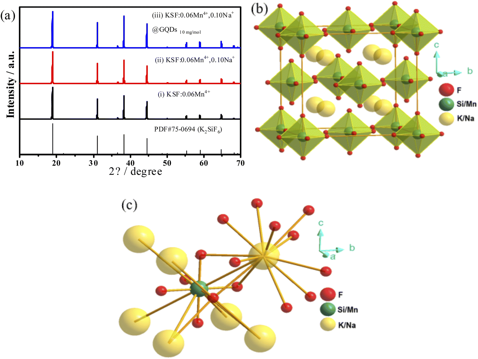 | ||
| Fig. 1 (a) XRD patterns of the three samples: (i) KSF: 0.06Mn4+, (ii) KSF: 0.06Mn4+, 0.10Na+, (iii) KSF: 0.06Mn4+, 0.10Na+ @ GQDs 10 mg mol−1, (b) The built unit cell structure of the sample (ii), (c) coordination environment surrounding Si/Mn. | ||
The results in Table 2 show that the lattice volumes of the samples are ranked as (i) > (iii) > (ii) > PDF#75-0694. The ionic radii (CN = 6) of Na+, K+, Si4+, Mn4+ are 1.18, 1.38,0.40, 0.53 Å, respectively.8,27,28 When Mn4+ is doped into the K2SiF6 matrix, some Si4+ in the lattice are replaced by Mn4+, resulting in the lattice volume (i) of the sample slightly larger than that of PDF#75-0694. Similarly, when the smaller radius Na+ replaces K+ in the matrix, the lattice volume of the sample (ii) is slightly reduced compared to that of the sample (i). Furthermore, the GQDs coated on the sample (iii) are coordinated to Mn4+ or Si4+, leading to an increase in its lattice volume compared to the sample (ii). Fig. 1b shows the crystal structure of the sample (ii), which belongs to the cubic crystal system and the Fm m (225) space group. In this structure, there is only one type of octahedral Si4+ ions (Fig. 1c).
Fig. 2 shows the XPS and FTIR spectra of the samples. In Fig. 2a, XPS depicts that the elements of the two samples (the samples (ii and iii)) are Na, K, Si, Mn, F, and C. The concentrations of Mn4+ and Na+ are very low, so the intensity of their peaks is not obvious. The FTIR spectra (Fig. 2b) shows that both the samples (ii and iii) have absorption peaks at 1640 cm−1, but the intensity of the two peaks differs considerably, with that of the sample (iii) being much stronger than that of the sample (ii). The absorption peaks at 1640 and 3500 cm−1 are probably from H2O, while the stronger absorption of the sample (iii) at 1640 cm−1 can be attributed to the overlapping peaks of the C![[double bond, length as m-dash]](https://www.rsc.org/images/entities/char_e001.gif) C vibrational peaks of the GQDs (Fig. S6†).29
C vibrational peaks of the GQDs (Fig. S6†).29
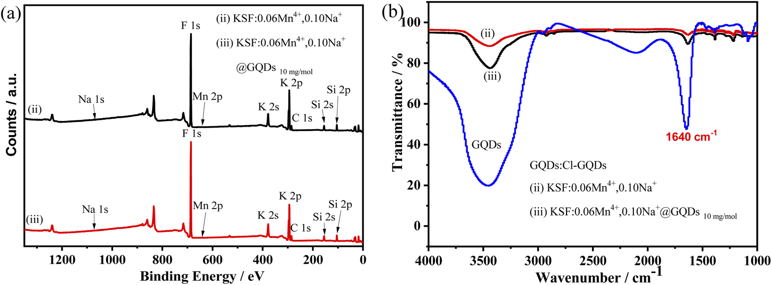 | ||
| Fig. 2 XPS and FTIR spectra of samples, (ii) KSF: 0.06Mn4+, 0.10Na+, and (iii) KSF: 0.06Mn4+, 0.10Na+ @ GQDs 10 mg mol−1 (a) XPS spectra, (b) FTIR spectra. | ||
Fig. 3 shows the EDS spectra and the SEM images of the samples (ii and iii). Fig. 3(a and b) show that the two samples consist of irregular lumpy particles of 2–5 μm in size, with the sample (iii) showing a clear agglomeration of particles. There are also some differences in the surfaces of the samples, with the sample (ii) having a smoother surface than that of the sample (iii). Fig. 3(c and d) illustrate that the sample (ii) consists of Na, K, Si, Mn, and F elements, and the elements Na, K, Si, Mn, F, and C appear in the sample (iii). The carbon peak (Fig. 3d) originates from the Cl-GQDs, however, no peak of Cl appears in the figure, probably because the chloride ions on the Cl-GQDs have been dissociated during the coating process. Based on the above results, it can be confirmed that the sample (iii) has been successfully coated with GQDs.
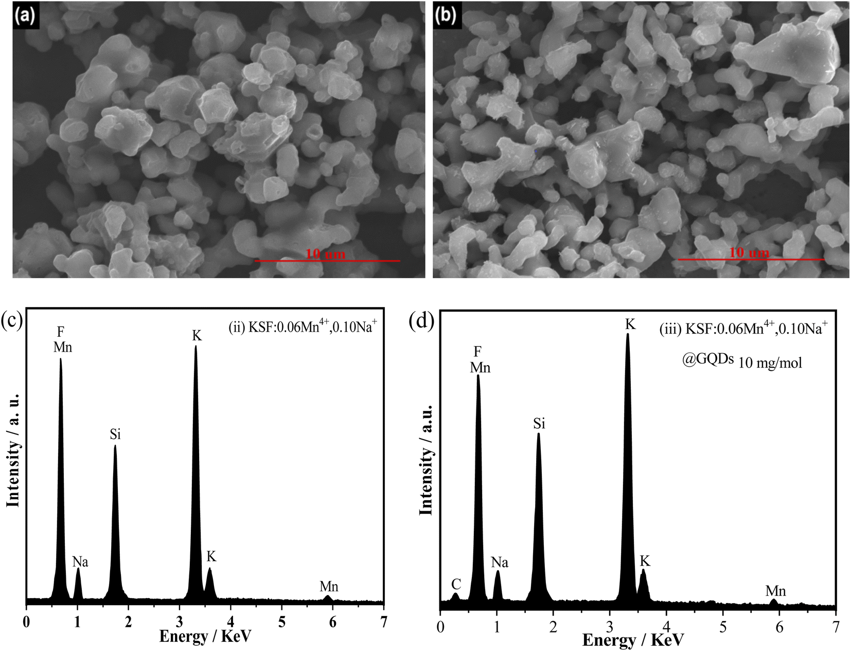 | ||
| Fig. 3 SEM images and EDS spectra of two samples, (ii) KSF: 0.06Mn4+, 0.10Na+ and (iii) KSF: 0.06Mn4+, 0.10Na+ @ GQDs 10 mg mol−1: (a and b) SEM images of sample (ii) and (iii) (c and d) EDS spectra. | ||
3.2. Luminescent properties at room temperature
The luminescent properties at room temperature of the samples ((0) KSF @ GQDs 10 mg mol−1, (i) KSF: 0.06Mn4+, (ii) KSF: 0.06Mn4+, 0.10Na+, (iii) KSF: 0.06Mn4+, 0.10Na+ @ GQDs 10 mg mol−1) are shown in Fig. 4(a and b).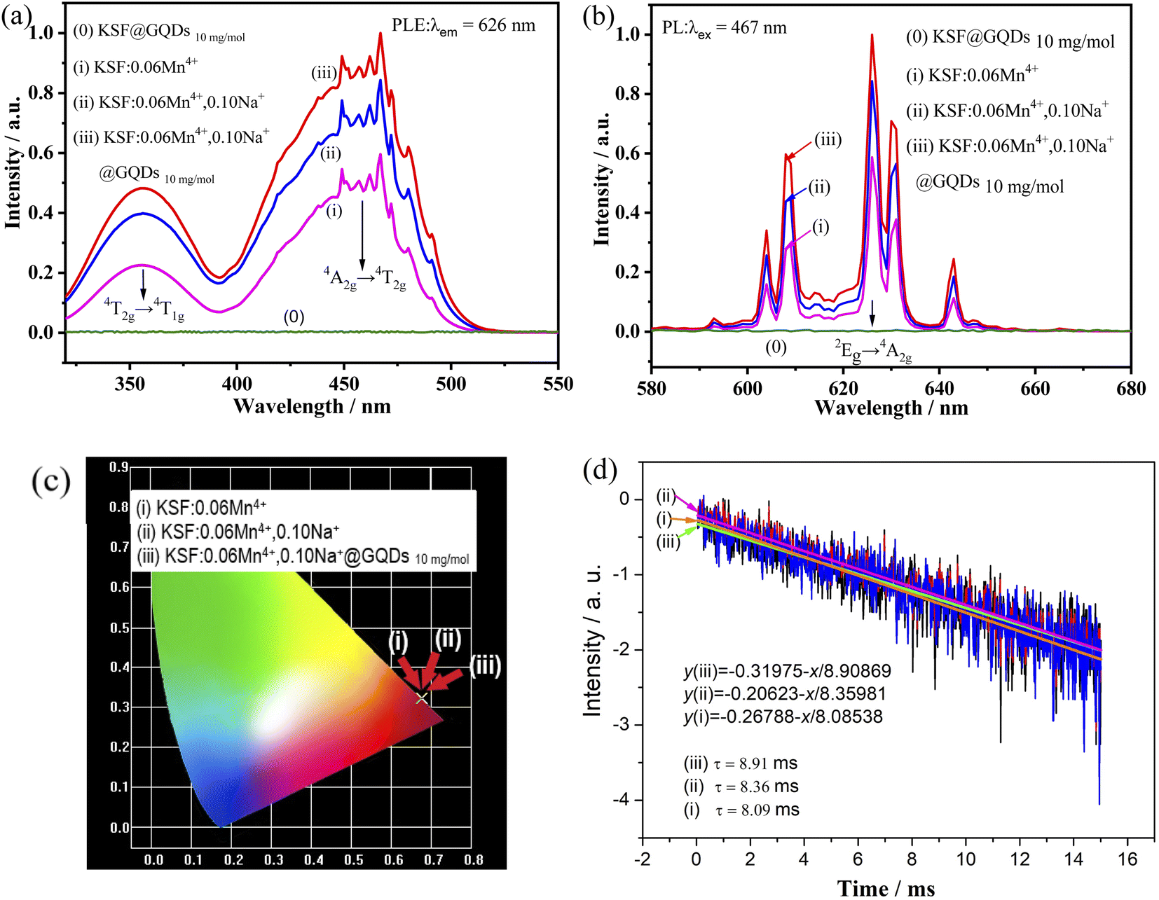 | ||
| Fig. 4 Luminescent properties of four samples, (0) KSF @ GQDs 10 mg mol−1, (i) KSF: 0.06Mn4+, (ii) KSF: 0.06Mn4+, 0.10Na+, (iii) KSF: 0.06Mn4+, 0.10Na+ @ GQDs 10 mg mol−1: (a) and (b) PLE and PL spectra, (c) CIE chromaticity diagram, (d) Lifetime curves of the samples (i–iii). | ||
Fig. 4(a and b) show that no excitation or emission peaks are present in the sample (0), indicating that KSF @ GQDs 10 mg mol−1 has no luminescence under blue light excitation, which is proven by Fig. 4b and S5.† The ratios of luminescence intensity of the samples (i)–(iii) in Fig. 4b are 1.00:1.44:1.70 respectively, indicating that fluorescence intensities of the samples are enhanced by doping with Na+ and further increased after coating with GQDs. The luminescent intensity of the sample (iii) is 1.18 times that of the sample (ii). The luminescence enhancements by doping with Na+ and coating with GQDs are also reported by Huang and Liu et al.22,30 respectively.
As shown in Fig. 4(a and b), the excitation and emission peaks of these samples are in essentially the same position. In PLE spectra, there are two strong broad excitation bands centered at ∼360 nm and ∼460 nm, which belong to the spin-allowed 4A2g → 4T1g and 4A2g → 4T2g transitions of Mn4+, respectively. The peaks in the PL spectrum occur in the 600–660 nm range, with the strongest peak at about 626 nm, which belongs to the 2Eg → 4A2g transition of Mn4+ (spin forbidden d–d transition),31,32 and it is activated by [MnF6]2− vibronic modes.33
Internal quantum yield (QYi) values of the samples (i)–(iii) are determined with the method described by some reports.34 The QYi of the samples (i)–(iii) are determined to be 83.36, 86.80, and 99.97%, respectively. It is clear that QYi (92%) of K2SiF6:Mn4+ reported by Xie et al.35 is smaller than that of the sample (iii).
It has been reported that QYi of K2TiF6:Mn4+ is larger than that of K2SiF6:Mn4+, and the former value is close to 100%.34 This shows that the QYi of the samples can be improved by coating with GQDs.36
The chromaticity coordinates of the samples are obtained by using the emission spectra data in Fig. 4b. The calculated results are shown in Fig. 4c ((i) (0.6776, 0.3222), (ii) (0.6771, 0.3227), (iii) (0.6762, 0.3236)). The formula (eqn (S1)†) is used for calculating color purity.37–39 The color purity of the samples (i–iii) are 99.70%, 99.84%, and 99.89% respectively, showing that the color purity of the sample coated with GQDs has been improved.
The luminescence decay curve of the sample can be well fitted by the linear equation (eqn (S3)†), which is transformed from eqn (S2):†40 Fluorescence lifetime curves for the samples (i–iii) fitted with the eqn (S3)† are shown in Fig. 4d, and the lifetimes obtained from the curves are τ (i) = 8.91 ms, τ (ii) = 8.36 ms, τ (iii) = 8.09 ms, respectively. The results show that the lifetime is enhanced by doping of Na+, then further improved by coating of GQDs. In contrast, the latter method has a greater enhancement effect than that of the former.
3.3. Luminescent properties of different samples
The influence of different molar ratios (atomic ratios) of Mn4+ on the fluorescent performances of KSF:yMn4+ is shown in Fig. 5a. The curve first shows an increasing trend, reaching a maximum at 6% mol Mn4+ doping concentration. Concentration quenching at higher concentrations leads to a decrease in fluorescence intensity.
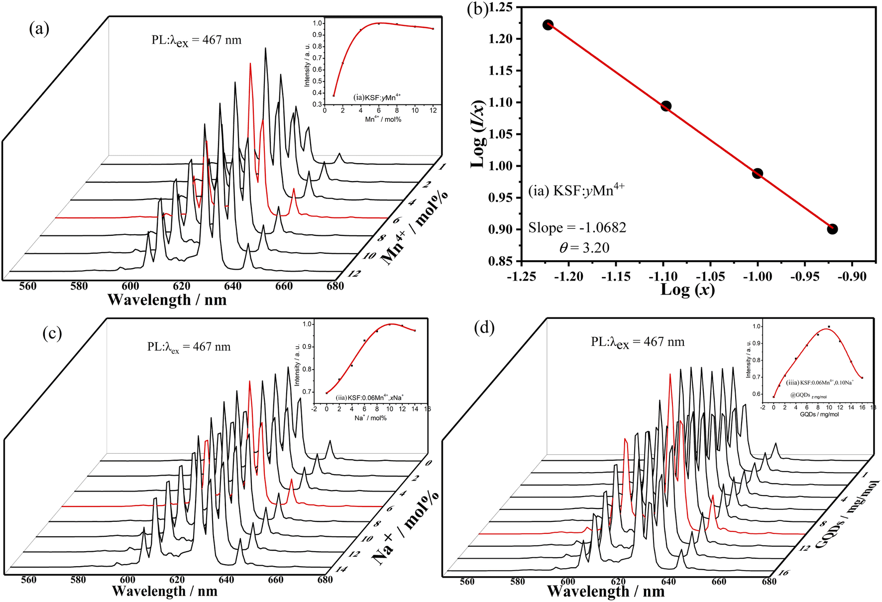 | ||
| Fig. 5 The luminescent properties of three samples, (i-a) KSF:yMn4+, (ii-a) KSF: 0.06Mn4+, xNa+, (iii-a) KSF: 0.06Mn4+, 0.10Na+ @ GQDs z mg mol−1: (a) and (c) and (d) PL spectra, (b) The related type line of multipolar interaction. | ||
The quenching mechanism of Mn4+ concentration in KSF:yMn4+ is explored by the critical distance (Rc) between Mn4+ ions. The Rc is calculated from eqn (S4).†39 For KSF: 0.06Mn4+, V = 538.22 Å3 and Rc is 23.42 Å. When Rc is much larger than 5 Å, the quenching mechanism of the Mn4+ concentration in KSF: 0.06Mn4+ may be due to multipolar interactions rather than interactions. Eqn (S5)†31,40 is used to estimate the multipolar interaction type for the sample. When θ are 6, 8, and 10, the corresponding mechanisms are the dipole–dipole, dipole–quadrupole, and quadrupole–quadrupole interactions, respectively. Fig. 5b shows that the slope of the KSF:yMn4+ straight line is −1.0682 and the value of θ is calculated as 3.20. Therefore, the quenching of the Mn4+ concentration in the KSF:yMn4+ sample corresponds to the mechanism of dipole–dipole interactions.
Based on KSF: 0.06Mn4+, the effect of doping with different Na+ concentrations on the fluorescence properties of KSF: 0.06Mn4+, xNa+ is shown in Fig. 5c. The influence curve is a parabola one with a maximum value. First, the curve goes up with the increase of x, and achieves a maximum value at x = 10%, then declines when y surpasses 10% due to the concentration quenching.
The influence of different coating concentrations of GQDs on the luminescent properties of KSF: 0.06Mn4+, 0.10Na+ @ GQDs z mg mol−1 was also investigated (Fig. 5d). The influence curve is nonlinear with a maximum value. First, the curve goes up with the increase of z, and achieves a maximum value at z = 10 mg mol−1, then it decreases when z exceeds 10 mg mol−1 due to concentration quenching.
3.4. Analyses of thermal performances
The fluorescence property changes with temperature is critical for WLEDs applications, due to the working temperature of WLEDs can reach about 150 °C. Fig. 6 shows the relationship between luminescence intensities of the samples (i–iii) and temperatures. Fig. 6a–c illustrate that the luminescence intensities of the three samples are strongly affected by temperature, but no emission shifts with increasing temperature.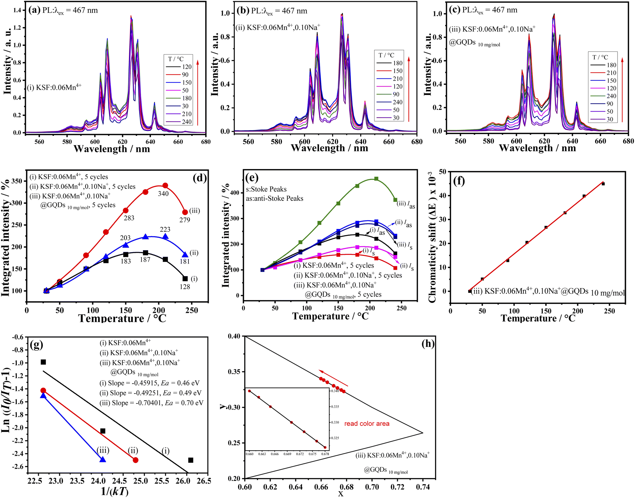 | ||
| Fig. 6 Temperature-dependent PL performances of three samples, (i) KSF: 0.06Mn4+, (ii) KSF: 0.06Mn4+, 0.10Na+, (iii) KSF: 0.06Mn4+, 0.10Na+ @ GQDs 10 mg mol−1: (a) and (b) and (c) PL spectra; (d) Integrated intensity curves; (e) Integrated intensity curves of Stoke and anti-Stoke peaks, (f) Chromaticity shift of sample (iii), (g) Ea curves, (h) CIE color coordinates of sample (iii). | ||
The relationship curves between integrated luminescence intensities of the samples and temperatures are parabola curves with their maximum values (Fig. 6d), which are analogous to that of K3AlF6:Mn4+ reported by Tang et al.20 First, with the increase of temperatures, the curves increase and achieve their maximum values at 180, 210, and 210 °C for the samples (i–iii), respectively. Meanwhile, Fig. 6d shows a NTQ effect for the three samples, and the luminescence intensity curves remain essentially constant after five cycles of testing (30–240 °C). The results of Fig. 6d indicate that the luminescent and chemical thermal stability of the sample are excellent. But the three curves of Fig. 6d have some differences. In contrast, the values of the three curves at 180, 210, and 240 °C are as follows: (a) 325, 340, and 279% for the sample (iii); (b) 222, 223, and 181% for the sample (ii); and (c) 187, 172, and 128% for the sample (i). So, the above results show that the three samples have high luminescence thermal stability. It can be seen that: (a) First, K2SiF6:yMn4+ obtained via the preparing method of this paper has the NTQ effect; (b) Second, after doping of Na+, the NTQ is obviously enhanced; (c) The NTQ is further enhanced by the coating of GQDs. As mentioned above, several Mn4+-doped phosphors prepared via various methods have the NTQ behavior.19–21 But, in most cases, they do not have the NTQ. The results of this paper and our previous work show that coating with GQDs is an effective method to synthesize red-emitting phosphors with the NTQ.22,26
Fig. 6e shows relationship curves between Wa, Ws of the samples (i–iii) and temperatures (here, Wa, and Ws are integrated intensities of anti-Stokes peaks and Stokes peaks, respectively). The curves are used to study the NTQ mechanism. Fig. 6e shows that curves of Wa and Ws are nonlinear curves with highest points, but the height of the former is greater than that of the latter, for every sample. When the temperatures are 180, 210, and 210 °C, the curves of the samples (i–iii) reach their maximum values, respectively. These NTQ behaviors of the anti-Stokes and the Stokes transitions can be expressed with eqn (S6a and S7).†36
Eqn (S6 and S7)† show that the Wa and Ws are increased with increasing temperatures. In addition, eqn (S6 and S7)† also indicate that the former can be enhanced faster than the latter with increasing temperature. The curve trend of Fig. 6e coincides with that of Fig. 6d.
Eqn (S6 and S7)† indicate that the increase in radiative transition probability induced by the phonon is greater than that of the non-radiative one, which may be used to explain the NTQ effect of the three samples. In conclusion, with the help of the phonon-induced transition, some of the heat energy is changed into luminous energy, resulting in the NTQ effect.
In addition, due to their large conjugated -bonds, GQDs can coordinate with Mn4+ as electron donors, resulting in a greater NTQ effect in the sample (iii) than in the samples (i) and (ii).
ΔE (chromaticity shift) at different temperatures is calculated with eqn (S8).†41,42 The smaller ΔE value means better color stability. Fig. 6f shows the ΔE values for the sample (iii) at different temperatures, and the curve is basically a straight line. According to the curve, ΔE is very small before 175 °C (ΔE = 31.98 × 10⁻³). By comparison, the ΔE of a commercial red-emitting phosphor (CaAlSiN3:Eu2+ (CSASNE)) at 175 °C is as high as 44 × 10−3,44 indicating the sample (iii) has good luminescence thermal stability for practical applications.
Ea (activation energy) of the phosphor is an important parameter in evaluation of thermal stability. The higher the activation energy is, the better the fluorescence thermal stability of the sample is. Eqn (S9)† is applied to calculate the Ea of the luminescent thermal quenching. Eqn (S10)† can be transformed from eqn (S9).†43,44
Calculated results of Ea values for the samples (i–iii) from eqn (S10)† are shown in Fig. 6g, which are 0.46, 0.49, and 0.70 eV, respectively. As a result, sample (iii) has the best fluorescence thermal stability.
Fig. 6h shows the trend of color coordinates of the sample (iii) at different temperatures, and it has a small shift in color coordinates, which may be due to the slight widening of emission peaks, suggesting it has good color stability.
TG curve of the sample (iii) is shown in Fig. 7. There is only 0.17% weight loss before 200 °C, which is attributed to volatilization of adsorbed water. Significant weight loss occurs at around 600 °C, indicating that it has good chemical thermal stability.
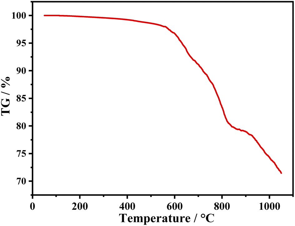 | ||
| Fig. 7 TG of sample, (iii) KSF: 0.06Mn4+, 0.10Na+ @ GQDs 10 mg mol−1. | ||
3.5. Performances of prototype WLED
In order to test practical application of the sample (iii), the sample (iii), YAG:Ce3+ and epoxy are mixed into a paste in proportion and coated on an InGaN chip to obtain an assembled prototype WLED. The electroluminescent properties of the WLED driven by a 20 mA current are shown in Fig. 8. Fig. 8a shows the electroluminescence spectrum of the WLED. The chromaticity coordinates of the WLED are (0.3694, 0.3304) (Fig. 8b), and the corresponding CCT is 3978 K. Besides, luminescent efficiency and Ra obtained from the performance test are 101.6 lm W−1 and 92.2, respectively. A luminescent photo of the WLED is illustrated in Fig. 8c, and it shows warm white light. Therefore, WLEDs with the sample (iii) as the red light component can meet the needs of practical applications.
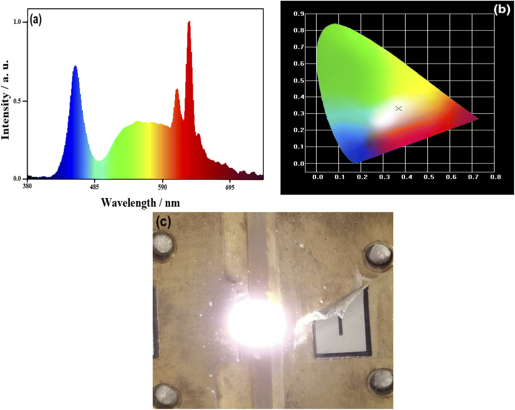 | ||
| Fig. 8 Performances of prototype WLEDs using the mixing phosphors of KSF: 0.06Mn4+, 0.10Na+ @ GQDs 10 mg mol−1 and YAG:Ce3+ based on InGaN chip under a 20 mA drive current: (a) Electroluminescence spectra, (b) CIE chromaticity diagram, (c) A photograph of the white emission spectrum of the driven LED. | ||
4. Conclusions
In summary, KSF:Mn4+, Na+ @ GQDs phosphors were synthesized by a combination of the H2O2-free method and hydrothermal coating method, where the best sample was KSF: 0.06Mn4+, 0.10Na+ @ GQDs 10mg mol−1. The fluorescence thermal stability and luminescence intensity of the phosphor were simultaneously enhanced by doping with Na+ and coating with GQDs: (a) The luminescent intensity ratios of the samples (i–iii) ((i)KSF: 0.06Mn4+, (ii) KSF: 0.06Mn4+, 0.10Na+, (iii) KSF: 0.06Mn4+, 0.10Na+ @ GQDs 10 mg mol−1) are 1.00:1.44:1.70; (b) the samples (i–iii) all have the NTQ effect, with the most pronounced effect in the sample (iii). The test results show that the sample (iii) has both fluorescence thermal stability and chemical thermal stability at the operating temperature (about 150 °C). A warm white light (luminescence efficiency = 101.6 lm W−1, CCT = 3978 K, and Ra = 92.2) was obtained for the assembled WLED prototype driven by a 20 mA current, indicating that the sample can be used as a high-power warm white light with good prospects applications in display and backlight filed.
Author contributions
Daishu Deng: methodology, formal analysis, investigation, writing – original draft. Yan Yu: investigation. Tianman Wang: investigation. Jun Lei: investigation. Lin Wang: investigation. Lin Wang: conceptualization, supervision. Yuelan Li: review & editing, visualization. Sen Liao: review & editing, visualization. Yingheng Huang: review & editing, visualization.Conflicts of interest
The authors declare no conflict of interest.Acknowledgements
This research is supported by the National Natural Science Foundation of China (Grant No. 21661006 and No. 21965004), the Natural Science Foundation of Guangxi Zhuang Autonomous Region, China (Grant No. 2019GXNSFDA245022, No. 2020GXNSFAA159036), the Scientific Research Foundation of Guangxi University (Grant No. XDZ140116), the innovation Project of Guangxi Graduate Education (Grant No. YCSW2020015), the Students Experimental Skills and Innovation Ability Training Fund Project of Guangxi University (No. S202210593143).References
- D. Q. Chen, W. D. Xiang, X. J. Liang, J. S. Zhong, H. Yu, M. Y. Ding, H. W. Lu and Z. G. Ji, J. Eur. Ceram. Soc., 2015, 35, 859–869 CrossRef CAS.
- J. H. Li, J. Yan, D. W. Wen, W. U. Khan, J. X. Shi, M. M. Wu, Q. Su and P. A. Tanner, J. Mater. Chem. C, 2016, 4, 8611–8623 RSC.
- Y. C. Lin, M. Karlsson and M. Bettinelli, Top. Curr. Chem., 2016, 37, 21 CrossRef PubMed.
- M. M. Shang, J. Fan, H. Z. Lian, Y. Zhang, D. L. Geng and J. Lin, Inorg. Chem., 2014, 53, 7748–7755 CrossRef CAS PubMed.
- D. Q. Chen, Y. Zhou and J. S. Zhong, RSC Adv., 2016, 6, 86285–86296 RSC.
- S. Ye, F. Xiao, Y. X. Pan, Y. Y. Ma and Q. Y. Zhang, Mater. Sci. Eng., R, 2010, 71, 1–34 CrossRef.
- L. Huang, Y. Liu, S. C. Si, M. G. Brik, C. X. Wang and J. Wang, Chem. Commun., 2018, 54, 11857–11860 RSC.
- L. Huang, Y. Liu, J. B. Yu, Y. W. Zhu, F. J. Pan, T. T. Xuan, M. G. Brik and C. X. Wang, ACS Appl. Mater. Interfaces, 2018, 10, 18082–18092 CrossRef CAS PubMed.
- H. Jia, L. Cao, Y. Wei, H. Q. Wang, H. Xiao, G. G. Li and J. Lin, J. Alloys Compd., 2018, 738, 307–316 CrossRef CAS.
- S. Sakurai, T. Nakamura and S. Adachi, Jpn. J. Appl. Phys., 2018, 57, 022601 CrossRef.
- T. Senden, R. J. A. van Dijk-Moes and A. Meijerink, Light: Sci. Appl., 2018, 7, 8 CrossRef PubMed.
- Y. W. Zhu, D. Q. Chen, L. Huang, Y. Liu, M. G. Brik, J. S. Zhong and J. Wang, J. Mater. Chem. C, 2018, 6, 3951–3960 RSC.
- Y. Jin, M. H. Fang, M. Grinberg, S. Mahlik, T. Lesniewski, M. G. Brik, G. Y. Luo, J. G. Lin and R. S. Liu, ACS Appl. Mater. Interfaces, 2016, 8, 11194–11203 CrossRef CAS PubMed.
- S. J. Qiu, H. W. Wei, M. M. Wang, S. Zhang, Y. Zhou, L. Xu, X. M. Wang and H. Jiao, RSC Adv., 2017, 7, 50396–50402 RSC.
- Z. L. Wang, Y. Liu, Y. Y. Zhou, Q. Zhou, H. Y. Tan, Q. H. Zhang and J. H. Peng, RSC Adv., 2015, 5, 58136–58140 RSC.
- Z. L. Wang, Y. Y. Zhou, Z. Y. Yang, Y. Liu, H. Yang, H. Y. Tan, Q. H. Zhang and Q. Zhou, Opt. Mater., 2015, 49, 235–240 CrossRef CAS.
- M. M. Zhu, Y. X. Pan, X. A. Chen, H. Z. Lian and J. Lin, J. Am. Ceram. Soc., 2018, 101, 4983–4993 CrossRef CAS.
- Y. W. Zhu, S. Yuan, L. Huang, Y. Liu, X. Y. Li, J. S. Zhong, Y. F. Chen, D. Q. Chen and J. Wang, Dalton Trans., 2019, 48, 711–717 RSC.
- H. D. Nguyen, C. C. Lin and R. S. Liu, Angew. Chem., Int. Ed., 2015, 54, 10862–10866 CrossRef CAS.
- X. Tang, X. D. Li, Z. H. Zou, Z. D. Ma, J. C. Zhang, Z. Z. Wang, Z. P. Ci, D. Y. Wang, S. L. Peng, H. H. Li and Y. H. Wang, J. Mater. Chem. C, 2017, 5, 10369–10374 RSC.
- Y. Y. Zhou, E. H. Song, T. T. Deng, Y. J. Wang, Z. G. Xia and Q. Y. Zhang, Adv. Mater. Interfaces, 2019, 6, 1802006 CrossRef.
- T. C. Lang, J. Y. Wang, T. Han, M. S. Cai, S. Q. Fang, Y. Zhong, L. L. Peng, S. X. Cao, B. T. Liu, E. Polisadova, V. Korepanov and A. Yakovlev, Inorg. Chem., 2021, 60, 1832–1838 CrossRef CAS PubMed.
- A. K. Srivastava, V. Gupta, C. S. Yerramalli and A. Singh, Composites, Part B, 2019, 179, 107539 CrossRef CAS.
- W. J. Zhang, X. F. Zou and J. F. Zhao, J. Mater. Chem. C, 2015, 3, 1294–1300 RSC.
- G. Anoop, J. R. Rani, J. Lim, M. S. Jang, D. W. Suh, S. Kang, S. C. Jun and J. S. Yoo, Sci. Rep., 2016, 6, 33993 CrossRef CAS PubMed.
- Y. L. Li, X. Zhong, Y. Yu, Y. M. Liu, S. Liao, Y. H. Huang and H. X. Zhang, Mater. Chem. Phys., 2021, 260, 124149 CrossRef CAS.
- Y. Gao, Q. W. Long, R. Nong, T. M. Wang, Y. H. Huang, S. Liao and H. X. Zhang, J. Electron. Mater., 2016, 46, 911 CrossRef.
- Y. M. Liu, T. M. Wang, Z. P. Chen, K. Y. Chen, M. M. Guan, Y. H. Huang, S. Liao and H. X. Zhang, J. Mater. Sci.: Mater. Electron., 2018, 29, 12536–12542 CrossRef CAS.
- Y. C. Zhao, L. J. Huang, Y. X. Wang, J. G. Tang, Y. Wang, J. X. Liu, L. A. Belfiore and M. J. Kipper, J. Alloys Compd., 2016, 687, 95–113 CrossRef CAS.
- S. Y. Wang, Q. Sun, B. Devakumar, J. Liang, L. L. Sun and X. Y. Huang, J. Lumin., 2019, 214, 116525 CrossRef CAS.
- M. G. Brik, S. J. Camardello and A. M. Srivastava, ECS J. Solid State Sci. Technol., 2014, 4, R39 CrossRef.
- Y. M. Liu, Y. L. Li, W. J. Huang, J. M. Meng, W. F. Liang, S. Liao, Y. H. Huang and H. X. Zhang, J. Mater. Sci.: Mater. Electron., 2019, 30, 14646–14656 CrossRef CAS.
- L. P. Dong, L. Zhang, Y. C. Jia, B. Q. Shao, W. Lü, S. Zhao and H. P. You, ACS Sustainable Chem. Eng., 2020, 8, 3357–3366 CrossRef CAS.
- J. C. D. Mello, H. F. Wittmann and R. H. Friend, Adv. Mater., 2010, 9, 230 CrossRef.
- Z. Y. Hou, X. Y. Tang, X. F. Luo, T. L. Zhou, L. Zhang and R. J. Xie, J. Mater. Chem. C, 2018, 6, 2741–2746 RSC.
- H. M. Zhu, C. C. Lin, C. W. Q. Luo, S. T. Shu, Z. G. Liu, Y. S. Liu, J. T. Kong, E. Ma, Y. G. Cao, R. S. Liu and X. Y. Chen, Nat. Commun., 2014, 5, 5312 CrossRef PubMed.
- L. Y. Wang, E. H. Song, Y. Y. Zhou, T. T. Deng, S. Ye and Q. Y. Zhang, J. Mater. Chem. C, 2017, 5, 7253–7261 RSC.
- W. T. Xu, Y. F. Zhou, D. C. Huang, M. Y. Su, K. Wang, M. Xiang and M. C. Hong, J. Mater. Chem. C, 2015, 3, 2003–2015 RSC.
- M. M. Zhu, Y. X. Pan, L. Q. Xi, H. Z. Lian and J. Lin, J. Mater. Chem. C, 2017, 5, 10241–10250 RSC.
- M. G. Brik, S. J. Camardello, A. M. Srivastava, N. M. Avram and A. Suchocki, ECS J. Solid State Sci. Technol., 2015, 5, R3067 CrossRef.
- X. J. Zhang, L. Huang, F. J. Pan, M. M. Wu, J. Wang, Y. Chen and Q. Su, ACS Appl. Mater. Interfaces, 2014, 6, 2709–2717 CrossRef CAS.
- X. J. Zhang, J. Wang, L. Huang, F. J. Pan, Y. Chen, B. F. Lei, M. Y. Peng and M. M. Wu, ACS Appl. Mater. Interfaces, 2015, 7, 10044–10054 CrossRef CAS PubMed.
- Y. W. Zhu, L. Huang, R. Zou, J. H. Zhang, J. B. Yu, M. M. Wu, J. Wang and Q. Su, J. Mater. Chem. C, 2016, 4, 5690–5695 RSC.
- Y. W. Zhu, L. Y. Cao, M. G. Brik, X. J. Zhang, L. Huang, T. T. Xuan and J. Wang, J. Mater. Chem. C, 2017, 5, 6420–6426 RSC.
Footnote |
| † Electronic supplementary information (ESI) available. See https://doi.org/10.1039/d2ra05527a |
| This journal is © The Royal Society of Chemistry 2022 |