
 Open Access Article
 This Open Access Article is licensed under a
 Creative Commons Attribution 3.0 Unported Licence
Water splitting by MnFe2O4/Na2CO3 reversible redox reactions†
Yimin Deng a,
Shuo Lib,
Raf Dewilac,
Lise Appelsa,
Miao Yangb,
Huili Zhangd and
Jan Baeyens*ab
a,
Shuo Lib,
Raf Dewilac,
Lise Appelsa,
Miao Yangb,
Huili Zhangd and
Jan Baeyens*ab
aKU Leuven, Department of Chemical Engineering, Process and Environmental Technology Lab, 2860, Sint-Katelijne-Waver, Belgium. E-mail: Jan.Baeyens@kuleuven.be
bBeijing University of Chemical Technology, Beijing Advanced Innovation Centre of Soft Matter Science and Engineering, 100029, Beijing, China
cUniversity of Oxford, Department of Engineering Science, Parks Road, Oxford, OX3 3PJ, UK
dBeijing University of Chemical Technology, School of Life Science and Technology, 100029, Beijing, China
First published on 2nd November 2022
Abstract
Future energy systems must call upon clean and renewable sources capable of reducing associated CO2 emissions. The present research opens new perspectives for renewable energy-based hydrogen production by water splitting using metal oxide oxidation/reduction reactants. An earlier multicriteria assessment defined top priorities, with MnFe2O4/Na2CO3/H2O and Mn3O4/MnO/NaMnO2/H2O multistep redox cycles having the highest potential. The latter redox system was previously assessed and proven difficult to be conducted. The former redox system was hence experimentally investigated in the present research at the 0.5 to 250 g scale in isothermal thermogravimetry, an electrically heated furnace, and a concentrated solar reactor. Over 30 successive oxidation/reduction cycles were assessed, and the H2 production efficiencies exceeded 98 % for the coprecipitated reactant after these multiple cycles. Tentative economics using a coprecipitated reactant revealed that 120 cycles are needed to achieve a 1 € per kg H2 cost. Improving the cheaper ball-milled reactant could reduce costs by approximately 30 %. The initial results confirm that future research is important.
1. Introduction
The future annual worldwide need for H2 was estimated by Liu et al.:1 reducing global CO2 emissions requires that at least 10% of hydrocarbons (currently 14 billion tons of oil equivalent2) be substituted by alternative renewable energy resources, including “green” H2. If only H2 is considered as a substitute energy carrier, approximately 1000 Mtons of nonfossil-based H2 are needed. Current H2 production is more than 10 times below the required 10% replacement target,3 but electrolysis using renewable energy is promoted. Neither hydropower3 nor nuclear energy are sufficient to meet this target.4 The nuclear energy production was only 25 exajoule (even less than 39 exajoule per year of hydropower). The negative public attitude towards nuclear energy and the limited reserves of uranium will probably not foster increased nuclear power.Currently, green electrolytic H2 can be produced using mostly wind or photovoltaic electricity. Its production requires an average electricity consumption of approximately 50 kW h kg−1 H2 at an overestimated efficiency of 80%.5 The 2019 global renewable energy production, without hydro-energy, was estimated at 2800 TW h. If these sources were devoted to solely produce H2, only 56 Mtons of electrolysis H2 could be generated, and this at a 2- to 4-fold production cost of the traditional petrochemical methods. Renewable technologies are therefore unable to meet the 1000 Mtons H2 goal.
It is therefore expected that fossil hydrocarbons will remain the important H2 sources in the near future, despite their environmental impact through CO2 emissions. Steam methane reforming yields approximately 10 kg of CO2 per kg H2, and is hence classified as “grey hydrogen” production method.3 The application of carbon capture and storage could make this technology “cleaner”, but involving significant costs to nearly double the price of the produced H2.6
Within the “green” H2 production methods,3 thermochemical water splitting by redox systems5 has a considerable potential, and is the subject of the present research. Alternative methods were, however, also investigated.7,8
1.1 H2 from multicycle thermal redox water splitting
Thermochemical redox water splitting reactions are candidates for H2 production. Water is abundant, inexpensive, and its decomposition or subsequent combustion is free from CO2 emissions. Thermochemically splitting water into H2 and O2 involves different reaction pathways, but the overall endothermic reaction (ΔH = 286 kJ mol−1) is H2O → H2 + ½O2.These thermochemical reactions to produce H2 offer major advantages in comparison with common alkaline water electrolysis, which has a low efficiency of approximately 20% (30% for electricity and 65% for electrolysis). The high-temperature thermochemical H2 production efficiency is much higher, provided cheap renewable or waste high-temperature heat is available.
These water splitting systems have been proposed since 1964. The initial vanadium–chlorine cycle was, however, abandoned for its low efficiency, high cost, and the formation of toxic and hazardous products. The cycles were however further developed, and approximately 25 thermochemical cycles are currently proposed. Deng et al. examined and ranked these proposed redox reactions by multiple criteria assessment, including quantified parameters of thermal, chemical, environmental and economic nature.5
Very high temperature reactions (≫ 1000 °C) of metal–metal oxides/hydroxides, doped ceria, or perovskites were not considered since such high temperatures would necessitate the application of high-cost alloys to construct redox reactors. Selected redox systems should operate at temperatures that would limit reactor wall temperatures below 1000 °C, thus operating the redox material bed at maximum 800 °C.5 Based on this important target, 4 out of 24 redox reactions were finally selected, and included MnFe2O4/Na2CO3, Mn3O4/MnO/NaMnO2, U3O8/UO2CO3 and ZnO/Fe3O4/ZnFe2O4. The U3O8 cycles were discarded due to nuclear hazards. The ZnO cycles scored significantly lower than both remaining redox systems, and were not further investigated. The Mn3O4/MnO/NaMnO2 four-step redox process was assessed, but required an operation temperature of approximately 800 °C and suffered from poor reversibility of the redox cycles.1 The MnFe2O4/Na2CO3 cycle remained the selected system under scrutiny.
1.2 Solar heat-induced redox systems
The use of solar energy in the redox cycles for H2 production was previously advocated.9,10 Metal oxide redox pairs are considered the simplest, and the most environmentally friendly. Solar heat supplies the sensible and reaction heats of the oxidation and reduction cycles. The ferrite system was shown to split water at low temperatures in the oxidation reaction and reduce CO2 in the reduction reaction.11–13 Solar-induced two-step water splitting by (Ni, Mn) ferrite and ZnO/MnFe2O4 was achieved at approximately 1000 K.14 The solar-based ZrO2-supported Co(II)-ferrite cycle was finally tested but the required temperatures of 1000 °C for the oxidation and 1400 °C for the reduction, and the attrition of the reactant during the reduction were prohibitive for its further application. Carbon-bearing systems failed in repeated cycles.12,131.3 Literature findings on MnFe2O4 and its applications
Spinel ferrites (MnFe2O4) are a significant class of magnetic materials, with excellent electrical properties. Their development is therefore mainly linked with electronic uses, for example shifters, frequency transformers, PCs, TV, cell phones, adsorbents, among other applications. Their use in water splitting was launched during the past decade.The manufacturing methods are diverse, with main objectives to produce MnFe2O4 particles of small size, high crystallinity, and large specific surface area. The comparison of the manufacturing methods and the relevant physicochemical properties is given in Table 1. The manufacturing methods used in the present research, i.e. by simple ball-milling and by co-precipitation, are included in the table.
| Synthesis method | Reaction T (°C) | Time (h) | Particle size (nm) | Surface area (m2 g−1) | Ref. |
|---|---|---|---|---|---|
| Polyol | 210 | 3 | 7 | 165.39 | 15 |
| Co-precipitation | 70 | 2 | 20–80 | 84.5 | 16 |
| 95 | 2 | 30 | — | 17 | |
| 50 | 3 | 24 | — | 18 | |
| 70 | 1 | 36 | — | 19 | |
| 75–80 | 6 | 14 | 0.293 (ref. 20) | 21 | |
| 80 | 6 | 80 | — | 22 | |
| Sol–gel | 70 | 2 | 45 | — | 19 |
| Ball milled | 900 | 1 | 6.78–8.06 | 23 | |
| Thermal decomposition | 295 | 1 | 7 | — | 24 |
| 270 | 1.5 | 18.9 | — | 25 | |
| Solution combustion | 300 | — | 30–35 | 33 | 26 |
| Hydrothermal | 200 | 12 | 30–50 | — | 27 |
| 220 | 10 | 14.5 | — | 28 | |
| 180 | 28 | 280 | 32.19 | 29 | |
| 180 | 16 | 16 | — | 19 | |
| Solvothermal | 200 | 24 | 8.6 | — | 30 |
| 180 | 12 | 60 | 70 | 31 | |
| 500–600 | 24 | 12–22 | — | 32 | |
| 200 | 8 | 250–260 | — | 33 | |
| Co-precipitation | 80 | 2 | 40 | 132 | This work |
| Ball milled | 20 | 1 | 100 | 4.92 | This work |
Whereas ball-milled reactant appears less performance due to its coarse particle size and low surface area, coprecipitated reactant seems to meet the main property targets. Our coprecipitation differs from other cited synthesis methods through its use of metal chlorides as precursors, rather than the previously favoured metal nitrates or sulphates.
The crystalline of both ball-milled and coprecipitated MnFe2O4, is determined from XRD analysis. The diffractograms of both reactants are shown in Fig. 1.
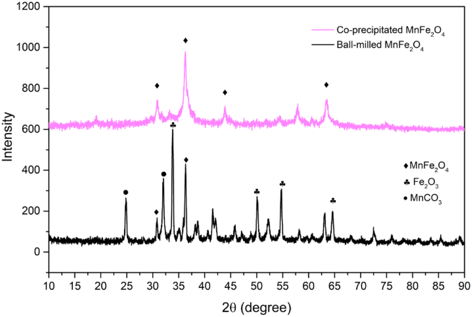 | ||
| Fig. 1 Diffractograms of the selected reactants. | ||
In both cases, diffraction peaks were matched with the respective references of the ICDD cards. The main peaks correspond to the space group Fd![[3 with combining macron]](https://www.rsc.org/images/entities/char_0033_0304.gif) m (spinel ferrite). The crystallite size for each phase was determined from the Sherrer's equation,34 accounting for the most intense XRD-peak. The crystal size, δ, is determined as:
m (spinel ferrite). The crystallite size for each phase was determined from the Sherrer's equation,34 accounting for the most intense XRD-peak. The crystal size, δ, is determined as:
The fairly novel application in water splitting relies on the thermochemical cycle of MnFe2O4/Na2CO3, as described by the following reactions:1
| 2MnFe2O4 (s) + 3Na2CO3 (s) + H2O (g) → 6Na(Mn1/3Fe2/3)O2 (s) + 3CO2 (g) + H2 (g) |
| 6Na(Mn1/3Fe2/3)O2 (s) + 3CO2 (g) → 2MnFe2O4 (s) + 3Na2CO3 (s) + 0.5O2 (g) |
The optimal operation temperature of both reactions is approximately 700 to 750 °C.35 H2 production at lower temperatures shows slower kinetics, and complete regeneration cannot be fully accomplished.36,37 The reduction step is problematic and less effective, although adding Fe2O3 could help to overcome the problem.38 The reduction step seems to pose a main problem for all the redox pairs that were reported,35,39 and the reaction kinetics are not fully defined. The problems in the oxygen-releasing step are amplified along with the increasing experimental scale.
Although literature is still scarce, earlier research was reported by Murmura et al.,39 and by Varsano et al.35 Both Murmura et al.39 and Varsano et al.35 used about 40 mg MnFe2O4/Na2CO3 at the lab-scale for temperatures between 700 and 800 °C, or 600 and 800 °C, respectively. The H2 yield obtained after 1 h of oxidation varied from 81% (700 °C) to 86% (800 °C).
Varsano et al.40 repeated the tests in a 1 kW concentrated solar facility at 750 and 800 °C and obtained H2 yields of approximately 20 to 37% at 750 °C, and ∼72% at 800 °C. The lower H2 efficiency in the solar-driven reactor was attributed to a nonuniform temperature within the solar reactor, and to a too coarse particle size (0.5–2 mm) used in the solar reactor.41 Such coarse particles have a very low active surface area. In general, the previous studies paid insufficient attention to the individual steps (oxidation and reduction), to the reaction kinetics, and to the long-duration and multicycle operation.
1.4 Objectives of the research
The art-to-date studies of redox systems were mostly limited to single steps of the cycles, with experiments performed on the milligram scale, and without considering long-duration cyclability and process economics. The present research will for the first time assess water splitting on a small and a larger scale, by thermogravimetric analysis (TGA), in an isothermal electric furnace, and in a concentrated solar rig. Realistic operating conditions and equipment scale will be accounted for. The study is limited to the priority-selected MnFe2O4/Na2CO3 cycles.1 It is expected that the results will provide better insight into thermochemical H2 production in equipment of different scales. Special attention will be given to the results obtained in multiple cycles, hence providing a better view of process economics, and scaling up.2. Materials and methods
2.1 Synthesis and main properties of redox reactants
The priority redox system under scrutiny involves a spinel MnFe2O4 and Na2CO3 according to the reaction of Section 1.3. The preparation of the MnFe2O4/Na2CO3 mixture involved either (i) a ball-mill method involving mostly MnCO3 and Fe2O3, or (ii) a coprecipitation method involving MnCl2·4H2O (manganese(II) chloride tetrahydrate) and anhydrous FeCl3 (iron(III) chloride, coprecipitated with sodium hydroxide (NaOH)). Na2CO3 (>99.9% purity) was purchased from Luchi Co., Ltd. Manganese(II) carbonate (>99.9% pure), iron(II) oxide (>96% pure), MnCl2 (>99% pure) and FeCl3 (>98% pure), were acquired from Sigma-Aldrich Chemie GmbH.In the ball-mill preparation,42 analytical grade MnCO3 and Fe2O3 were used without further treatment. They were mixed for 40 minutes at a molar ratio of 3![[thin space (1/6-em)]](https://www.rsc.org/images/entities/char_2009.gif) :2 in a 1000 rpm Simoloyer CM01 mixer/mill at ambient conditions and after the addition of ethanol (96%). 5 mm diameter stainless steel balls were used at a weight ratio of 6 with respect to the reactant's mix. Ethanol was evaporated at 378 K. The dried reactant was calcined in N2 atmosphere at 973 K for 1 hour, and re-milled in a Retsch mill. The calcination under N2 is needed to activate the reactants before their first use.
:2 in a 1000 rpm Simoloyer CM01 mixer/mill at ambient conditions and after the addition of ethanol (96%). 5 mm diameter stainless steel balls were used at a weight ratio of 6 with respect to the reactant's mix. Ethanol was evaporated at 378 K. The dried reactant was calcined in N2 atmosphere at 973 K for 1 hour, and re-milled in a Retsch mill. The calcination under N2 is needed to activate the reactants before their first use.
For the coprecipitated MnFe2O4, an aqueous solution of 0.5 mol MnCl2 and 1 mol FeCl3 were mixed at 60 °C with continuous stirring at 250 rpm. Subsequently, a 0.64 mol NaOH solution was added. The solution was maintained at 80 °C for 1 h. The precipitates were centrifuged and wasted 5 times with distilled water at 80 °C (to remove excess NaOH and formed NaCl). After drying at 105 °C and calcination at 450 °C during 2 h, the powder was milled in a Retsch mill into fine particles (<50 μm). The chemical reaction is presented as
| MnCl2 + 2FeCl3 + xNaOH + H2O → MnFe2O4 + (x − 8)NaOH + 8NaCl + 3H2O |
For the experiments in the vertical and solar furnaces, inert olivine was added to form a porous fixed bed, or to be able to operate the solar reactor in an isothermal fluidized mode by improving the heat transfer from the reactor wall to the fluidized bed of reactants. Malvern laser-diffraction and confirming SEM-imaging were used to determine the particle size distributions, which were mostly Gaussian with a narrow size distribution. This is illustrated in Table 2 for the feedstock particles. The near-spherical olivine particles (Mg, Fe-silicates) had a Waddell sphericity factor ψ of 0.8–0.9.41 The sphericity of all reactants was considered close to 0.84. These particles were further milled and processed into smaller particles. The pulverized mixtures had an ultrafine particle size, well below 2 μm, with smaller particles of approximately 150 nm.
| Chemicals | dv (μm) | dsv (μm) | σ (μm) |
|---|---|---|---|
| MnCO3 | 10.9 | 9.2 | 5 |
| Na2CO3 | 394.5 | 331.3 | 36.5 |
| MnCl2 | 6.4 | 5.9 | 0.5 |
| Fe2O3 | 5.6 | 5.3 | 0.3 |
| Olivine (100–150 mesh) | 167.9 | 142.7 | 18.9 |
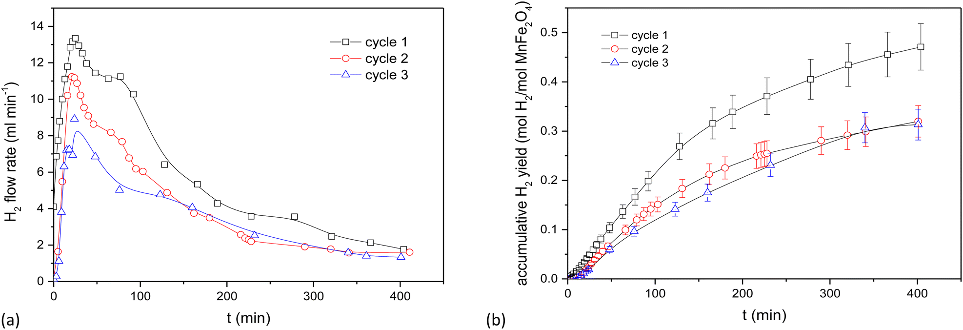
Particle size was measured by diffractometry, and the BET surface area (m2 g−1; Brunauer–Emmett–Teller) was determined in a Micromeritics instrument by low-temperature (−196 °C) nitrogen adsorption. SEM images are shown in Fig. 2 for the prepared MnFe2O4 compound reactants (ball-milled and coprecipitated). The ball-milled reactant particles have an agglomerated particle diameter of ∼60 μm (Fig. 2a) and are composed of smaller (∼0.1 μm) grains. Higher magnifications of coprecipitated reactant (Fig. 2b) show that smaller particles of 50 to 150 nm size are obtained. The coprecipitated reactants have a higher specific surface area (132 m2 g−1) than the ball-milled reactants (4.9 m2 g−1).
 | ||
| Fig. 2 SEM images of MnFe2O4, as-synthesized at 700 °C (a) ball-milled; (b) coprecipitated. | ||
2.2 Experimental setups and reactants
Three experimental setups were used, an electrically-heated vertical furnace for initial guidance tests, a TGA for long-duration experiments in multiple cycles, and a pilot-scale concentrated solar rig with ongoing experiments in the solar high season. Each of the experimental setups comprises the same elements.N2 (carrier gas) and CO2 feeds are set by mass flow meters. H2O is added by a syringe pump. The N2/H2O (oxidation cycle) or CO2 (reduction cycle) flows are preheated before being added into the water splitting reactor. The reactors are either vertical furnaces or TGA cells. After the reaction, the exhaust gas is cooled and dehumidified before being sent to a GC-MS for component monitoring. CO2 was removed from the gas by absorption in a 1.5 g L−1 Ca(OH)2 solution. The reactors contained appropriate quantities of reactant particles. A full description of the setups and the applied experimental procedures are given in ESI-3.† Olivine was sometimes added to increase the porosity and flowability of the reactants. The ball-milled reactant was prepared by milling 7.05 g ferrite and 4.87 g Na2CO3. For coprecipitation reactant, 53.94 g of MnFe2O4 was mixed with 37.18 g of Na2CO3. The bed heights in the electrically heated furnace were 15 cm, against 25 cm in the solar reactor.
The GC-MS continuously monitored and recorded the H2 concentration in the oxidation step, and the O2 concentration in the reduction step.
3. Results and discussion
3.1 The MnFe2O4 system in the electrically heated furnace
The use of the electrically heated setup is tedious and requires frequent dismantling to obtain reactant samples. Its results however provide data for a relatively deep bed and facilitate a kinetic analysis at a fair sample scale.The behaviour of the activated MnFe2O4 reactant was assessed for 3 subsequent oxidation–reduction steps each at 700 °C. The reverse step used pure CO2 for 3 h. Time-dependent H2 production values are illustrated in Fig. 3 for coprecipitated MnFe2O4, and in Fig. 4 for ball-milled MnFe2O4. The results were cumulated and expressed in mol H2 per mol MnFe2O4. The coprecipitated reactant significantly performs better than the reactant produced by ball milling.
 | ||
| Fig. 3 Results of the WS reaction cycle (700 °C) for co-precipitated MnFe2O4 at different oxidation time, but with a fixed reduction cycle of 3 h. (a) WS cycles of MnFe2O4 (coprecipitation). (b) Cumulative results for the WS cycles of MnFe2O4 (coprecipitation). | ||
 | ||
| Fig. 4 Results for ball-milled MnFe2O4 at different oxidation time, but with a fixed reduction cycle of 3 h. (a) WS cycles of MnFe2O4 (ball milling). (b) Cumulative results for the WS cycles of MnFe2O4 (ball milling). | ||
Since it was seen that the ball-milled reactant had a significantly lower H2-yield than its coprecipitated alternative, these tests were terminated after 60 min. It was moreover evident that reduction times longer than 3 h were needed. According to Chen et al.,43 the oxygen release (step 2 of the reaction cycle) between layered Na(Mn1/3Fe2/3)O2 and CO2 is fairly slow and requires >3 h to be completed.44,45 This was further investigated by TGA, where it was demonstrated that the reduction step preferably requires 4.5 to 6 h. Stoichiometrically, the yield should be 0.5 mol H2 per mol MnFe2O4, which is only closely achieved for the coprecipitated reactant. Regrinding of the reactants between the cycles slightly increased the H2 yield. It was hence tentatively presumed that agglomeration or sintering of the reactant took place between cycles during different days. The effect of agglomeration can be mitigated by grinding or reactivating the reactants.
For the ball-milled reactant, the poor performance can be explained by the incomplete reaction of Fe2O3, MnCO3 and Na2CO3. Although some MnFe2O4 can be recovered after one cycle, some iron is segregated and forms Fe2O3 phase. The Fe2O3 phase will react with Na2CO3 and form NaFeO2, thus causing a decrease in H2 productivity between the first and second cycle due to difficulties in regeneration step. The unreacted Fe2O3 when synthesizing the ball-milled catalysts also exacerbated the decrease in H2 yield between cycles compared to the coprecipitated ones.
The solid–solid contact and ions transportation are equally important for the regeneration step. According to Chen et al.,43 smaller particle size with moderate crystallinity is beneficial to maintain its structure stability and can lead to a better ionic transport within the crystals than through the grain boundaries in order to finish the whole cycle. This also counts for the difference in H2 yield between the first two cycles. The particles smaller than 30 nm are good for the contact with Na2CO3 to release H2 in the first step, but hamper removing Na+ from the lamellar Na(Mn1/3Fe2/3)O2 oxide considering the low layered structure stability.
The cyclic O2/H2 production was however achieved. Fig. 5 compares typical SEM images of the ball-milled and coprecipitation reactants after water splitting at 700 °C. The particles synthesized by ball-milling (Fig. 5a) formed agglomerates consisting of 0.1 μm dense grains. The co-precipitation reactant maintains a size in the order of 50–150 nm (Fig. 5b). The porous morphology of the MnFe2O4 reactants is maintained even after calcination and reaction at 700 °C.
 | ||
| Fig. 5 MnFe2O4 and olivine, after water splitting at 700 °C (a) ball milled; (b) coprecipitation. | ||
The time-dependent conversion allows the study of the reaction kinetics. To evaluate appropriate kinetic models,26 data were transformed in terms of reaction progress, α. These data were normalized against the conversion at α = 50%. All data transformations revealed similar fitting profiles, as illustrated in Fig. 6.
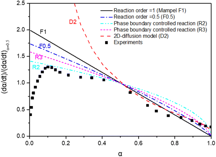 | ||
Fig. 6 Kinetic models applied to the experimental results: α is the reaction fraction  . . | ||
The MnFe2O4 water splitting is controlled by different reaction models. A 2D geometrical-contracting model (R2) seems appropriate when α < 0.5. For α > 0.5, a first-order (F1) or 2D diffusion model (D2) seems more appropriate. The morphology of Mn seems essential to the H2 generation reaction kinetics. This is also the case for MnOx-based water splitting reactions.43 An additional kinetics study was carried out based upon the TGA results, as reported below.
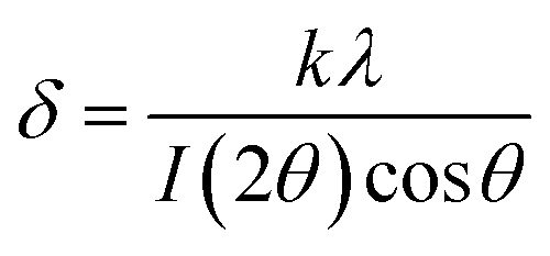
3.2 The MnFe2O4 system studied in multicycle TGA experiments
TGA experiments provide an easy follow-up of the reaction progress through the weight changes of the sample under scrutiny. With a stoichiometric weight loss during the oxidation step of 83.18% (including the added O from H2O), this theoretical limit forms the reference value for all the results. These results are illustrated in the following figures, obtained for a fixed oxidation duration of 3 h, but a variable reduction cycle of 3, 4.5 and 6 h.The experimental results of Fig. 7 clearly demonstrate that a 3 hour CO2-induced reduction cycle is insufficient to restore the initial activity of the reactant. The reaction was hence stopped after 7 cycles. This finding confirms the electrically heated furnace results.
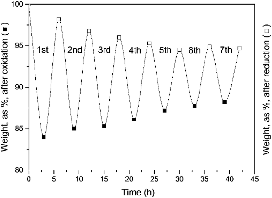 | ||
| Fig. 7 Weight evolution of the oxidation (3 h) and reduction cycles (3 h). Seven cycles were examined. | ||
Long-duration, multicycle experiments with reduction cycles of 4.5 and 6 h were performed, and the results (Fig. 8a and b) clearly demonstrated that a longer reduction cycle enhances the recyclability.
 | ||
| Fig. 8 Cyclic experiments at different reduction cycle times. (a) Weight evolution of, respectively the oxidation (3 h) and reduction cycles (4.5 h). (b) Weight evolution of, respectively the oxidation (3 h) and reduction cycles (6 h). (c) The first 7 cycles at a fixed oxidation time (3 h) but variable reduction time (3, 4.5, and 6 h, respectively). (d) H2 yield efficiency. | ||
All results for the first 7 cycles (with different total cycle times) are represented in Fig. 8c.
Finally, the system H2 efficiency is calculated as follows, and presented in Fig. 8d:
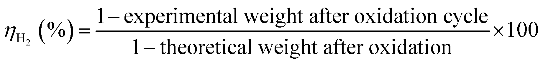
The efficiency of the combined (3 + 6) h cycles exceeded 98% after 33 cycles, again 95% only for the (3 + 4.5) h operation. It is hence recommended to combine a 3 h oxidation (H2 release) with 6 h of reduction (O2 release).
The TGA results enable the calculation of the apparent reaction rate constant (k). Since α ≫ 0.5, first-order kinetics can be applied. Table 3 summarizes the results for the given numbers of cycles and a specific reduction time (3, 4.5, and 6 h).
| Reaction rate constant (min−1) | Reduction time | ||
|---|---|---|---|
| 3 h | 4.5 h | 6 h | |
| Cycle 1 | 2.23 × 10⁻² | 3.17 × 10⁻² | 3.54 × 10⁻² |
| Cycle 6 | 1.68 × 10⁻² | 2.72 × 10⁻² | 3.07 × 10⁻² |
| Cycle 30 | — | 1.77 × 10⁻² | 2.22 × 10⁻² |
The reaction rate decreases with the number of cycles for a given duration of the reduction, corresponding to a progressive but limited loss of activity of the solid reactant. The rate constant however increases when the reduction time is increased. It is hence important to either extend the oxidation cycle beyond 3 h as cycling proceeds, or to re-activate the reactants more frequently by calcination and/or re-milling after a certain number of cycles.
The reaction mechanism of the water splitting has been investigated by several researchers, both in electrocatalytic and thermochemical routes. Zhou et al.46,47 studied the electrocatalytic reduction reaction (ORR), also called the hydrogen evolution reaction (HER), and oxygen evolution reaction (OER). Four elementary reaction steps are proposed, including OOH and OH species. Spin-polarized DFT simulations demonstrate that the reaction step are reported to be slow.48 These 4 steps were confirmed by computational screenings.49 The thermochemical mechanism was assessed by Chen et al.43 and Angotzi et al.50 with special emphasis on the slow oxygen release (over 3 h) of the Na(Mn1/3Fe2/3)O2 intermediate. In the hydrogen release step, lamellar Na(Mn1/3Fe2/3)O2 oxide is formed by intercalating a Na+ layer into two adjacent oxygen interspaces.51 Both intercalation of Na+ into adjacent oxygen interspaces and the Jahn–Teller effect lead to a more stable Na(Mn1/3Fe2/3)O2 oxide. The full mechanism is presented in Chen et al.43
3.3 Preliminary results of the MnFe2O4 system in the solar reactor
Preliminary tests were performed with a solar reactor, during the first oxidation cycle. The temperature of the front reactor wall in the cavity was kept below 900 °C (thermal strength limits of the Ni/Cr construction alloy). The slow reaction of the heliostat focusing leads to temperature variations in the bed between 700 and 750 °C. Average values of 710 °C and 735 °C were maintained over a period of 5 h. The solar H2 production was very good and the theoretical H2 yield of 0.5 mol mol−1 was nearly achieved at 735 °C, as shown in Fig. 9. | ||
| Fig. 9 Solar H2 production using the MnFe2O4/Na2CO3 cycle. | ||
Further to the TGA observations and prior to conducting additional cycling experiments that are now taking place in the season of high direct normal irradiance (DNI), the rig was adapted to conduct oxidation and reduction steps in parallel in the single cavity, as illustrated in Fig. 10.
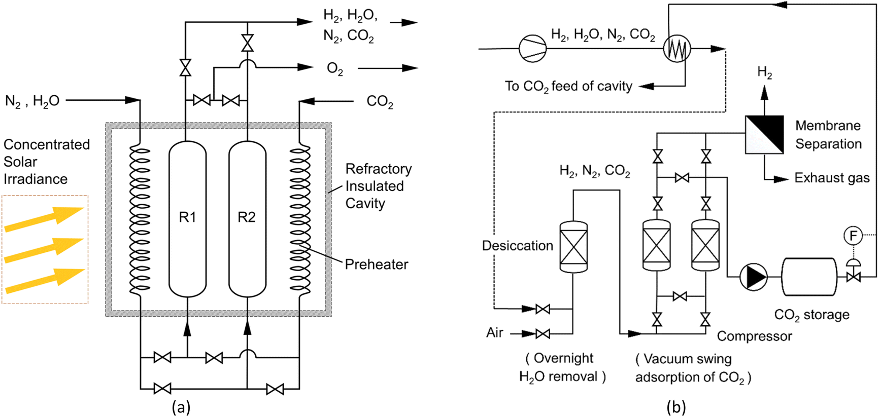 | ||
| Fig. 10 (a) Installing redox-reactors in the cavity; (b) purification cycles of H2. Cycle 1 oxidation (R1) progresses in parallel with the reduction cycle (R2) by appropriate value settings. The next solar day, the functions of (R1) and (R2) are reversed. | ||
The H2 upgrading will apply a sequence of steps, involving the removal of excess H2O vapour; the removal of CO2 by vacuum swing adsorption6 on appropriate adsorbents, e.g. zeolite, activated carbon, or others;52,53 a membrane permeation of H2, e.g. using a Matrimid 521854 or P84 membranes55 with over 95% H2 purity and 96% recovery. The use of sintered metal fibre filters at the reactor exhausts limits the loss of reactant.56
4. Recyclability
Results confirmed that the H2 production efficiency can be ≫95% provided oxidation and reduction cycles are properly performed. A conservative 95% efficiency can be accepted, as obtained both in TGA and in the solar receiver. For 0.5 mol of H2 per mol reactant, a maximum of ∼0.41 wt% H2 can be generated. Coprecipitated MnFe2O4 is purchased at approximately 500 € per ton. The ball-milled reactant can be approximately 30% cheaper.The heating costs are not considered since the system is supposed to use excess photovoltaic or wind turbine electricity, or to operate on concentrated solar heat. Heat recovery will be maximized by good heat management. The number of required cycles (Nc), to break even can be calculated for a proposed selling cost of H2, since:

CO2 should be separated, stored, and used in the reverse reaction. It is also proposed to use membrane modules to produce very pure H2.54,55
The solar energy balance is currently being assessed. At 4 € per kg H2 and 500 € per ton of reactants, 30 cycles should be realized to break even. To reach 1 € per kg H2, 120 cycles should be achieved, and this is presumed possible in view of the obtained cycling results. If the cheaper ball-milled reactant could be improved, the number of required cycles to break even will be reduced.
5. Conclusions
This research demonstrated the high potential of water splitting by the MnFe2O4/Na2CO3 redox pair. Coprecipitated MnFe2O4 offers approximately 30% higher H2 productivity than its cheaper ball-milled equivalent. Experiments in an electrically-heated reactor were used to study the fundamentals, possible shortcomings, and kinetics. TGA experiments demonstrated the long-duration and multicycle (up to 37 cycles) potential. Preliminary solar reactor experiments confirm the >95% H2 efficiency: these solar experiments are ongoing in a joint oxidation/reduction parallel reactor, installed in the solar cavity. The CO2 reaction time should be approximately 6 h to achieve a good reduction. Tentative cost calculations showed a break-even operation for 30 consecutive cycles at H2 prices of 4 € per kg H2. At least 120 cycles before reactant regeneration will reduce the H2 production cost to ∼1 € per kg H2. This implies the use of a cheap energy supply, and the complete reuse of CO2 in the reduction reaction. The results certainly foster a further improvement of the system.Author contributions
R. Dewil and J. Baeyens supervised the research. Y. Deng, S. Li, and M. Yang designed and performed the experiments. L. Appels and H. Zhang participated in the data analyses and discussions. Y. Deng, R. Dewil, and J. Baeyens wrote the paper. All authors discussed the results and commented on the manuscript.Conflicts of interest
There are no conflicts to declare.Acknowledgements
We gratefully acknowledge the support of the Fundamental Research Fund for the Central Universities (JD2220), and from the Beijing Advanced Innovation Center for Soft Matter Science and Engineering of Beijing University of Chemical Technology.Notes and references
- J. Liu, S. Li, R. Dewil, M. Vanierschot, J. Baeyens and Y. Deng, Sustainability, 2022, 14, 7597 CrossRef CAS.
- W. Antweiler, What role does hydrogen have in the future of electric mobility?, https://wernerantweiler.ca/blog.php?item=2020-09-28 Search PubMed.
- S. Li, Q. Kang, J. Baeyens, H. L. Zhang and Y. M. Deng, IOP Conf. Ser.: Earth Environ. Sci., 2020, 544, 012011 CrossRef.
- BP p.l.c, Hydroelectricity, https://www.bp.com/en/global/corporate/energy-economics/statistical-review-of-world-energy/hydroelectricity.html Search PubMed.
- Y. Deng, R. Dewil, L. Appels, S. Li, J. Baeyens, J. Degrève and G. Wang, Renewable Energy, 2021, 170, 800–810 CrossRef CAS.
- C. Chao, Y. Deng, R. Dewil, J. Baeyens and X. Fan, Renewable Sustainable Energy Rev., 2021, 138, 110490 CrossRef CAS.
- Z. Li, H. Zhang, R. Dewil, Y. Deng and S. Li, IOP Conf. Ser.: Earth Environ. Sci., 2022, 952, 012007 CrossRef.
- C.-J. Winter and J. Nitsch, Hydrogen as an energy carrier: technologies, systems, economy, Springer Science & Business Media, 2012 Search PubMed.
- S. Baykara, Int. J. Hydrogen Energy, 2004, 29, 1451–1458 CrossRef CAS.
- J. E. Funk, Int. J. Hydrogen Energy, 2001, 26, 185–190 CrossRef CAS.
- Y. Tamaura and M. Tahata, Nature, 1990, 346, 255–256 CrossRef CAS.
- T. Sano, N. Hasegawa, M. Tsuji and Y. Tamaura, J. Mater. Chem., 1996, 6, 605–609 RSC.
- T. Sano, T. Togawa, M. Kojima, M. Tsuji and Y. Tamaura, Energy, 1996, 21, 377–384 CrossRef CAS.
- M. Inoue, N. Hasegawa, R. Uehara, N. Gokon, H. Kaneko and Y. Tamaura, Sol. Energy, 2004, 76, 309–315 CrossRef CAS.
- S. R. Sabale, Mater. Today: Proc., 2020, 23, 139–146 CAS.
- R. Asadi, H. Abdollahi, M. Gharabaghi and Z. Boroumand, Adv. Powder Technol., 2020, 31, 1480–1489 CrossRef CAS.
- N. Akhlaghi, G. Najafpour-Darzi, A. Barras, M. Mohammadi, R. Boukherroub and S. Szunerits, Chem. Pap., 2021, 75, 377–387 CrossRef CAS.
- I. Elahi, R. Zahira, K. Mehmood, A. Jamil and N. Amin, Afr. J. Pure Appl. Chem., 2012, 6, 1–5 CAS.
- L. A. Kafshgari, M. Ghorbani and A. Azizi, Part. Sci. Technol., 2019, 37, 904–910 CrossRef.
- G. Wang, Y. Zeng, F. Zhou, X. Chen, Y. Ma, L. Zheng, M. Li, Y. Sun, X. Liu, H. Liu and R. Yu, J. Alloys Compd., 2020, 819, 153044 CrossRef CAS.
- A. A. Ati, A. H. Abdalsalam and A. S. Hasan, J. Mater. Sci.: Mater. Electron., 2021, 32, 3019–3037 CrossRef CAS.
- J. Amighian, M. Mozaffari and B. Nasr, Phys. Status Solidi C, 2006, 3, 3188–3192 CrossRef CAS.
- A. Hassan, W. Ding, M. A. Aslam, Y. Bian, Q. Liu and Z. Sheng, J. Mater. Res. Technol., 2020, 9, 12869–12879 CrossRef CAS.
- H. Yang, C. Zhang, X. Shi, H. Hu, X. Du, Y. Fang, Y. Ma, H. Wu and S. Yang, Biomaterials, 2010, 31, 3667–3673 CrossRef CAS PubMed.
- G. Singh and S. Chandra, Int. J. Hydrogen Energy, 2018, 43, 4058–4066 CrossRef CAS.
- R. H. Vignesh, K. V. Sankar, S. Amaresh, Y. S. Lee and R. K. Selvan, Sens. Actuators, B, 2015, 220, 50–58 CrossRef CAS.
- J. Kwon, J.-H. Kim, S.-H. Kang, C.-J. Choi, J. A. Rajesh and K.-S. Ahn, Appl. Surf. Sci., 2017, 413, 83–91 CrossRef CAS.
- H. Tombuloglu, G. Tombuloglu, Y. Slimani, I. Ercan, H. Sozeri and A. Baykal, Environ. Pollut., 2018, 243, 872–881 CrossRef CAS PubMed.
- W. Zhang, X. Hou, Z. Lin, L. Yao, X. Wang, Y. Gao and S. Hu, J. Mater. Sci.: Mater. Electron., 2015, 26, 9535–9545 CrossRef CAS.
- K. Vamvakidis, M. Katsikini, D. Sakellari, E. C. Paloura, O. Kalogirou and C. Dendrinou-Samara, Dalton Trans., 2014, 43, 12754–12765 RSC.
- Z. Liu, G. Chen, X. Li and X. Lu, J. Alloys Compd., 2021, 856, 158185 CrossRef CAS.
- M. Goodarz Naseri, E. Bin Saion, H. A. Ahangar, M. Hashim and A. H. Shaari, J. Magn. Magn. Mater., 2011, 323, 1745–1749 CrossRef CAS.
- X.-Y. Long, J.-Y. Li, D. Sheng and H.-Z. Lian, Talanta, 2017, 166, 36–45 CrossRef CAS PubMed.
- F. T. L. Muniz, M. A. R. Miranda, C. Morilla dos Santos and J. M. Sasaki, Acta Crystallogr., Sect. A: Found. Adv., 2016, 72, 385–390 CrossRef CAS PubMed.
- F. Varsano, M. A. Murmura, B. Brunetti, F. Padella, A. La Barbera, C. Alvani and M. C. Annesini, Int. J. Hydrogen Energy, 2014, 39, 20920–20929 CrossRef CAS.
- F. Padella, C. Alvani, A. La Barbera, G. Ennas, R. Liberatore and F. Varsano, Mater. Chem. Phys., 2005, 90, 172–177 CrossRef CAS.
- H. Kaneko, Y. Hosokawa, N. Gokon, N. Kojima, N. Hasegawa, M. Kitamura and Y. Tamaura, J. Phys. Chem. Solids, 2001, 62, 1341–1347 CrossRef CAS.
- L. Seralessandri, M. Bellusci, F. Padella, A. Santini and F. Varsano, Int. J. Hydrogen Energy, 2009, 34, 4546–4550 CrossRef CAS.
- M. A. Murmura, F. Varsano, F. Padella, A. La Barbera, C. Alvani and M. C. Annesini, Ind. Eng. Chem. Res., 2014, 53, 10310–10317 CrossRef CAS.
- F. Varsano, F. Padella, C. Alvani, M. Bellusci and A. La Barbera, Int. J. Hydrogen Energy, 2012, 37, 11595–11601 CrossRef CAS.
- A. Mottana, R. Crespi and G. Liborio, Simon & Schuster's guide to Rocks and Minerals, Simon and Schuster, New York, 1991 Search PubMed.
- L. Y. Dolgikh, I. L. Stolyarchuk, L. A. Staraya, I. V. Vasylenko, Y. I. Pyatnitsky and P. E. Strizhak, Catal. Petrochem., 2020, 1–10 Search PubMed.
- Z. Chen, Q. Jiang, J. Tong, M. Yang, Z. Jiang and C. Li, Sol. Energy, 2016, 129, 236–243 CrossRef CAS.
- S. Li, H. Zhang, J. Nie, R. Dewil, J. Baeyens and Y. Deng, Sustainability, 2021, 13, 8866 CrossRef CAS.
- C. C. Agrafiotis, C. Pagkoura, A. Zygogianni, G. Karagiannakis, M. Kostoglou and A. G. Konstandopoulos, Int. J. Hydrogen Energy, 2012, 37, 8964–8980 CrossRef CAS.
- Y. Zhou, Y. Du, S. Xi and Z. J. Xu, Electrocatalysis, 2018, 9, 287–292 CrossRef CAS.
- Y. Zhou, G. Gao, J. Kang, W. Chu and L.-W. Wang, Nanoscale, 2019, 11, 18169–18175 RSC.
- Y. Singh, S. Back and Y. Jung, Phys. Chem. Chem. Phys., 2018, 20, 21095–21104 RSC.
- Y. Yang, J. Liu, F. Liu, Z. Wang and D. Wu, J. Mater. Chem. A, 2021, 9, 2438–2447 RSC.
- M. Sanna Angotzi, V. Mameli, C. Cara, D. Peddis, H. L. Xin, C. Sangregorio, M. L. Mercuri and C. Cannas, Nanoscale Adv., 2021, 3, 1612–1623 RSC.
- C. Alvani, G. Ennas, A. Labarbera, G. Marongiu, F. Padella and F. Varsano, Int. J. Hydrogen Energy, 2005, 30, 1407–1411 CrossRef CAS.
- Y. Deng, J. P. K. Seville, S. D. Bell, A. Ingram, H. Zhang, N. Sweygers, R. Dewil, J. Baeyens and L. Appels, Sep. Purif. Rev., 2021, 1–12 Search PubMed.
- J. P. K. Seville, Y. Deng, S. Dawn Bell, R. Dewil, L. Appels, R. Ansart, T. Leadbeater, D. Parker, H. Zhang, A. Ingram and J. Baeyens, Chem. Eng. J., 2021, 404, 126507 CrossRef CAS.
- R. Castro-Muñoz, V. Martin-Gil, M. Z. Ahmad and V. Fíla, Chem. Eng. Commun., 2018, 205, 161–196 CrossRef.
- G. Li, Z. Si, S. Yang, T. Xue, J. Baeyens and P. Qin, Chem. Eng. Sci., 2022, 253, 117588 CrossRef CAS.
- S. Li, J. Baeyens, R. Dewil, L. Appels, H. Zhang and Y. Deng, Renewable Sustainable Energy Rev., 2021, 139, 110713 CrossRef CAS.
Footnote |
| † Electronic supplementary information (ESI) available. See DOI: https://doi.org/10.1039/d2ra05319e |
| This journal is © The Royal Society of Chemistry 2022 |