 Open Access Article
Creative Commons Attribution 3.0 Unported Licence
A novel choline chloride/graphene composite as a shale inhibitor for drilling fluid and the interaction mechanism
Heming Zhua,
Daqi Lia,
Xiangyang Zhaoa,
Shaocong Pangbc and
Yuxiu An *bc
*bc
aKey Laboratory of Shale Oil and Gas Enrichment Mechanism and Development, Sinopec Research Institute of Petroleum Engineering, Changping District, Beijing 100101, China. E-mail: zhuhm.sripe@sinopec.com; lidq.sripe@sinopec.com; zhaoxy.sripe@sinopec.com
bSchool of Engineering and Technology, China University of Geosciences (Beijing), Haidian District, Beijing 100083, China. E-mail: P7426cong@163.com; anyx@cugb.edu.cn
cKey Laboratory of Deep Geo Drilling Technology, Ministry of Land and Resources, Beijing 100083, China
First published on 24th October 2022
Abstract
For wellbore stability in shale formations, the development of environmentally friendly and efficient shale inhibitors is urgently needed. Herein, we report the preparation of choline chloride-modified graphene (Ch-G). The inhibition and interaction mechanisms of choline chloride-modified graphene on montmorillonite were also investigated. We evaluated the inhibition of Ch-G via linear swelling and rolling recovery and selected the inorganic salt inhibitor KCl as the control group. The lowest swelling height of 2.10 mm and the highest rolling recovery of 78.87% were achieved, indicating the excellent inhibition performance of Ch-G. The mechanism of inhibition of Ch-G was determined by Fourier transform infrared spectroscopy, X-ray diffraction, X-ray photoelectron spectroscopy, transmission electron microscopy, scanning electron microscopy, and atomic force microscopy. The Ch-G formed hydrogen bonds, coordination, and electrostatic interactions with the surface of montmorillonite and entered the montmorillonite via intercalation to achieve the inhibition. The increase in the nitrogen atom content in Ch-G led to the production of more positive ions and the formation of more ion bands, which enhanced the ability to inhibit shale hydration. The addition of Ch-G produced larger montmorillonite sheets, demonstrating its effective inhibition ability, which is needed to enable drilling fluids to stably drill into shale formations.
1. Introduction
Oil and gas resources are an indispensable part, and there is an urgent need for efficient drilling to extract oil and gas resources.1 Shale is used as source and reservoir rock, and 75% of drilling formations for oil and gas resources are in shale formation.2 As the main component of shale, clay minerals, mainly composed of montmorillonite, will expand when they encounter water, causing wellbore safety problems.3,4 Although clay minerals in shale are not hydrated in oil-based drilling fluids (OBDFs), OBDFs have problems such as high cost, non-biodegradability, and being harmful to environmental health.5 Nowadays, relevant environmental protection agencies are becoming more and more strict with treatments that are harmful to the environment, and finally water-based drilling fluids (WBDFs) have been selected for drilling. However, drilling with WBDFs in shale formations to exploit resources faces a major problem, that is, the shale is extremely easy to swelling. This means that it will bring wellbore stability problems such as hole collapse and economic losses and will seriously affect the progress of the project.6 Therefore, inhibiting the hydration of shale is the key for WBDFs to be used for drilling in shale formations.An inhibitor is a treatment agent that inhibits the hydration of shale and is added to form an inhibitory drilling fluid.7 Much research has been done on shale inhibitors; the earliest used was the inorganic salt KCl, which switched weakly hydrated potassium ions (K+) for sodium ions (Na+).8 Other inhibitors include CaCl2, NH4Cl, modified hard bitumen, and bitumen.9,10 KCl/sodium silicate drilling fluid can inhibit shale hydration in the formation with strong sensitivity.11 However, high concentrations of K+ have not been allowed to exist in the formation due to consideration of environmental protection.12–15 In addition, functional cationic polyquaternary amine polymers, amphoteric poly amino acids, nonionic polymers, and cationic polymers have also been studied.16–18 Quaternary ammonium groups were introduced to synthesize inhibitors together with gelatin, which showed better inhibition at high temperatures.19 Xu et al. synthesized polymer microsphere emulsions, which could block shale nanopores and reduce shale hydration capacity due to their tiny particle size.20 Most of the inhibitors played the role of inhibiting shale hydration by entering the montmorillonite intercalation, charge neutralization, and plugging shale pores. Changes in the wettability of shale surfaces by inhibitors were also investigated.21 Organosilicon quaternary ammonium salts were prepared to act as shale inhibitors, which could form hydrophobic films on shale surfaces through chemical reactions. Therefore, the wettability of the shale surface changed, resulting in a greatly reduced water adsorption capacity. In strengthening the hydrophobic shielding of clay, imidazolyl-based ionic liquids for shale inhibitors have also been studied.22,23 However, some shale inhibitors still have low toxicity and poor inhibitory performance at high temperatures, even having a bad impact on drilling fluid rheology.24 It is particularly urgent to research an environmentally friendly and effective shale inhibitor.19,25,26
As a research hotspot in this century, graphene materials have attracted the interest of researchers because of their good physical and electronic properties.27–29 In the field of drilling engineering, graphene has been studied as a filter loss agent, and it has been found to cause a good filter loss reduction.30 In view of the lubricating properties of graphene materials, lubricants based on graphene materials were used in water-based drilling fluids.31 They relied on adsorption to form a layer of film on the surface of the filter cake, which reduced the wear of drilling tools and slightly reduced the filtration of drilling fluid. Recently, there have been studies on graphene materials for shale inhibitors.32 Lv et al. obtained a shale inhibitor with better performance by modifying dodecylamine and graphene oxide.33 Since graphene is a nanosheet with an atom-thick 2-position conjugated structure, it can form a dense film on shale and it can also block the nanopores of shale. Choline chloride could also be used in shale inhibitors due to its stable anti-swelling properties and high efficiency, as well as its non-toxic and biodegradable advantages.34 It is well known that there are many nanopores in shale. Graphene is a flexible nanosheet that can block the nanopores of shale formations, preventing clay swelling caused by water intrusion.35 Therefore, graphene materials and choline chloride materials are considered to have great potential for environmentally friendly shale inhibitors.
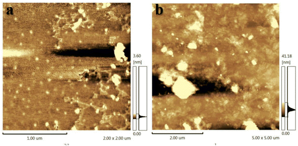
In this paper, choline chloride-modified graphene (Ch-G) was obtained by blending graphene and choline chloride. The linear swelling height and rolling recovery rate were tested to evaluate the performance of Ch-G in inhibiting hydration swelling of shale in water-based drilling fluids. The inhibition mechanism of Ch-G was also investigated by Fourier transform infrared spectroscopy, X-ray diffraction, X-ray photoelectron spectroscopy, scanning electron microscopy, transmission electron microscopy, and atomic force microscopy.
2. Experimental section
2.1 Materials
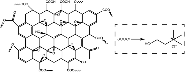
Montmorillonite (MMT) was provided by HuaWei Company. Choline chloride was obtained from Alfa Reagent Company. Graphene oxide (GO) was provided by XianfenNano Company. The other materials such as KCl, xanthan gum (XC) were all provided by a domestic reagent company. All materials were used as obtained without further purification. The chemical structure of the choline chloride/graphene oxide composite is shown in Fig. 1.2.2 Methods
![[thin space (1/6-em)]](https://www.rsc.org/images/entities/char_2009.gif) :
:![[thin space (1/6-em)]](https://www.rsc.org/images/entities/char_2009.gif) 200 and dissolved to uniformity via mild sonication. Then, 40 ml of choline chloride was added to the solution and refluxed at 80 °C for 8 hours.
200 and dissolved to uniformity via mild sonication. Then, 40 ml of choline chloride was added to the solution and refluxed at 80 °C for 8 hours.2.3 Characterization techniques
![[thin space (1/6-em)]](https://www.rsc.org/images/entities/char_2009.gif) sin
sin![[thin space (1/6-em)]](https://www.rsc.org/images/entities/char_2009.gif) θ = nλ (λ = 0.15406 nm, n = 1).
θ = nλ (λ = 0.15406 nm, n = 1).3. Results and discussion
3.1 FT-IR
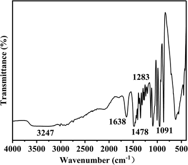
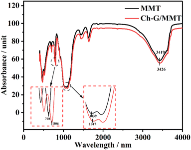
The structure of Ch-G was characterized by FT-IR and the spectrum is shown in Fig. 2. Peaks at 1091 cm−1 and 1283 cm−1 were attributed to the bending vibration absorption peaks of C–O and C–O–C, respectively. The peak at 1638 cm−1 was due to the C=C skeleton vibration of the benzene-like ring on graphene oxide. The curved vibration peak of –CH2 on the chlorine chloride appeared at 1478 cm−1. The peak at 3247 cm−1 was due to the stretching vibration of –OH. All these proved the successful preparation of Ch-G.3.2 Linear swelling tests
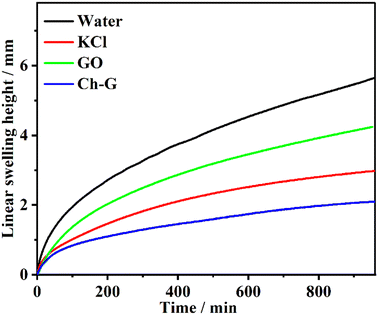
The inhibition effect of the shale inhibitor is reflected in the inhibition of clay hydration and swelling, resulting in a low swelling height. The swelling height curves of compacted bentonite in different inhibitor solutions were obtained by linear swelling tests and can be seen in Fig. 3. The inhibitor solution was divided into a water solution, 4 wt% KCl solution, 4 wt% Ch-G solution and 0.2 wt% GO solutions. The swelling heights of bentonite in these four solutions showed the same trend, increasing rapidly and then slowly. After 400 min, the growth rate of the Ch-G curve gradually stabilized, while the curve of the water solution was in a growing state. The swelling height of bentonite in the Ch-G solution was the lowest, which was 2.10 mm. The swelling height of bentonite in water solution was the highest, and the swelling height reached 5.64 mm after 16 h. The most common inorganic salt KCl inhibitor was selected as the control group. The final swelling height of bentonite in KCl solution reached 2.98 mm; compared with the water solution, the swelling height decreased, and KCl showed an inhibition. Compared with GO, Ch-G reached the reduction rate of the swelling height with 50.47%. This indicated that the introduction of choline chloride played a great role in the inhibitory effect of Ch-G. The results showed that the prepared Ch-G exhibited a good ability to inhibit the hydration and swelling of MMT.3.3 Rolling recovery tests
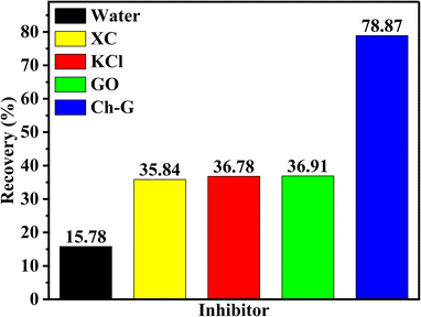
Shale cuttings are rich in clay and are easily hydrated and dispersed in water. After the inhibition of shale inhibitors, more unhydrated shale debris is recycled in the rolling recovery test. Therefore, rolling recovery tests were performed to evaluate the inhibitory performance of shale cuttings containing unhydrated dispersed clays. Fig. 4 shows the rolling recoveries of shale cuttings in water, XC solution, KCl solution, GO solution, and Ch-G solution at 120 °C. The shale rolling recovery in water was the lowest. Compared with the GO solution, the rolling recovery in the Ch-G solution increased from 36.91% to 78.87%. This indicated that the introduction of choline chloride enabled Ch-G to inhibit the hydration and dispersion of shale cuttings and increase the amount of recoverable shale cuttings. Ch-G could still maintain a high recovery rate after high temperature hot rolling because of the hydrogen bonds and ionic bonds formed between choline chloride and graphene oxide. In actual drilling engineering, a high rolling recovery rate is more conducive to solid-phase separation operations. The high shale rolling recovery rate of Ch-G solution indicated that there was the potential for the application of Ch-G as an effective shale inhibitor.3.4 Inhibition mechanism analysis
| Sample | O | C | Si | Al | N |
|---|---|---|---|---|---|
| Ch-G/MMT | 47.65 | 27.82 | 13.74 | 5.88 | 4.89 |
| GO/MMT | 54.34 | 28.09 | 11.52 | 5.58 | 0.44 |
3.5 Probable inhibition mechanism
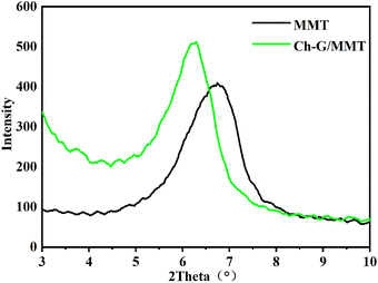
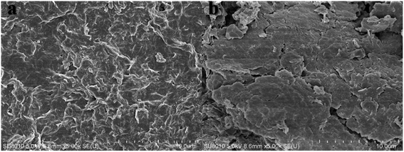
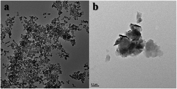
Ch-G inhibition was investigated and it was found that Ch-G was better than the traditional inhibitor KCl at inhibiting the hydration swelling of clay particles in shale. The sodium ions between the MMT layers acted as easily hydrated cations to form an electric double layer, so that the MMT could form a thick hydration film for hydration and dispersion. However, Ch-G was adsorbed on the MMT surface through electrostatic attraction and hydrogen bonding, neutralized the negative charge on the MMT surface, and compressed the electric double layer. At the same time, due to the intercalation of Ch-G, water molecules were prevented from entering the interlayer of MMT. Therefore, the MMT clay particles agglomerated into large particles, and hydration dispersion was inhibited. The inhibition of Ch-G was beneficial to the stability of the wellbore.4. Conclusions
In this work, we prepared choline chloride-modified graphene (Ch-G) as a shale inhibitor and its inhibition mechanism was investigated. The inhibition of Ch-G was better than that of the traditional inhibitor KCl. Compared with MMT in aqueous solution and KCl solution, the addition of Ch-G achieved the lowest swelling height of 2.10 mm. Rolling recovery tests showed that Ch-G maintained the highest recovery rate of 78.87% after rolling at 120 °C. The inhibition mechanism was discussed further. Hydrogen bonds and ion bands were formed between Ch-G and the MMT surface. With the increase in the nitrogen atom content, the positive ions in the solution increased, which neutralized the negative charge on the surface of MMT and inhibited the expansion of the diffused electric double layer. The intercalation of Ch-G in MMT further prevented water intrusion and optimized the inhibition effect. The results showed that Ch-G could effectively inhibit shale expansion as an environmentally friendly shale inhibitor. On the other hand, the compatibility of Ch-G with other reagents commonly used in drilling fluids needs to be further studied. The next step is in progress.Conflicts of interest
There are no conflicts to declare.Acknowledgements
We would like to thank the financial support from Basic Research Program on Deep Petroleum Resource Accumulation and Key Engineering Technologies (U19B6003) for support.References
- E. S. Kazak and A. V. Kazak, J. Pet. Sci. Eng., 2019, 183, 106301 CrossRef CAS.
- M. Hammad Rasool, M. Ahmad, M. Ayoub, A. Zamir and M. Adeem Abbas, J. Mol. Liq., 2022, 361, 119673 CrossRef CAS.
- M. A. Abbas, A. Zamir, K. A. Elraies, S. M. Mahmood and M. H. Rasool, J. Pet. Sci. Eng., 2021, 204, 108745 CrossRef CAS.
- Y. An and P. Yu, J. Pet. Sci. Eng., 2018, 161, 1–8 CrossRef CAS.
- T. A. Saleh, A. Rana and M. K. Arfaj, Environ. Nanotechnol., Monit. Manage., 2020, 14, 100348 Search PubMed.
- K. Wang, G. Jiang, X. Li and P. F. Luckham, Colloids Surf., A, 2020, 606, 125457 CrossRef CAS.
- F. Huadi, C. Aldea, B. Mackereth and T. Mukhlis, presented in part at the IADC/SPE Asia Pacific Drilling Technology Conference and Exhibition, 2010 Search PubMed.
- J. L. Suter, P. V. Coveney, R. L. Anderson, H. C. Greenwell and S. Cliffe, Energy Environ. Sci., 2011, 4, 4572–4586 RSC.
- N. Davis II and C. E. Tooman, SPE Drill. Completion, 1989, 4, 47–56 CrossRef.
- N. Gholizadeh-Doonechaly, K. Tahmasbi and E. Davani, presented in part at the SPE International Symposium on Oilfield Chemistry, 2009 Search PubMed.
- J. Guo, J. Yan, W. Fan and H. Zhang, J. Pet. Sci. Eng., 2006, 50, 195–203 CrossRef CAS.
- A. Aftab, A. R. Ismail and Z. H. Ibupoto, SPE Drill. Completion, 2017, 26, 291–299 Search PubMed.
- Z. Luo, L. Wang, P. Yu and Z. Chen, Appl. Clay Sci., 2017, 150, 267–274 CrossRef CAS.
- X. Zhao, Z. Qiu, B. Sun, S. Liu, X. Xing and M. Wang, J. Pet. Sci. Eng., 2019, 173, 112–121 CrossRef CAS.
- G. Chen, J. Yan, L. Lili, J. Zhang, X. Gu and H. Song, Appl. Clay Sci., 2017, 138, 12–16 CrossRef CAS.
- A. D. Patel, presented in part at the SPE International Symposium on Oilfield Chemistry, 2009 Search PubMed.
- K. Xiong, P. Ma, F. Yong, F. Qian, R. Yang and Y. Meng, presented in part at the IADC/SPE Asia Pacific Drilling Technology Conference and Exhibition, 2012 Search PubMed.
- F. Ma, X. Pu, B. Wang, J. Li and C. Cao, RSC Adv., 2017, 7, 49320–49328 RSC.
- X. Li, G. Jiang, L. Yang, K. Wang, H. Shi, G. Li and X. Wu, Energy Fuels, 2019, 33, 9342–9350 CrossRef CAS.
- J.-g. Xu, Z. Qiu, X. Zhao, T. Mou, H. Zhong and W. Huang, RSC Adv., 2018, 8, 20852–20861 RSC.
- X. Huang, J. Sun, J. Jin, K. Lv, H. Li, K. Rong, C. Zhang and X. Meng, J. Mol. Liq., 2021, 341, 117369 CrossRef CAS.
- H. Jia, P. Huang, Q. Wang, Y. Han, S. Wang, J. Dai, J. Song, F. Zhang, H. Yan and K. Lv, J. Mol. Liq., 2020, 301, 112401 CrossRef CAS.
- Y. Ren, H. Wang, Z. Ren, Y. Zhang, Y. Geng, L. Wu and X. Pu, Appl. Clay Sci., 2019, 182, 105248 CrossRef CAS.
- J. Ma, P. Yu, B. Xia, Y. An and Z. Wang, ACS Appl. Bio Mater., 2019, 2, 4303–4315 CrossRef CAS PubMed.
- Y. Xuan, G. Jiang, Y. Li, L. Yang and X. Zhang, RSC Adv., 2015, 5, 84947–84958 RSC.
- S. Gou, T. Yin, Q. Xia and Q. Guo, RSC Adv., 2015, 5, 32064–32071 RSC.
- A. K. Geim and K. S. Novoselov, Nat. Mater., 2007, 6, 183–191 CrossRef CAS PubMed.
- Q. Wu, Y. Xu, Z. Yao, A. Liu and G. Shi, ACS Nano, 2010, 4, 1963–1970 CrossRef CAS.
- G. Paul, H. Hirani, T. Kuila and N. C. Murmu, Nanoscale, 2019, 11, 3458–3483 RSC.
- D. V. Kosynkin, G. Ceriotti, K. C. Wilson, J. R. Lomeda, J. T. Scorsone, A. D. Patel, J. E. Friedheim and J. M. Tour, ACS Appl. Mater. Interfaces, 2012, 4, 222–227 CrossRef CAS.
- J. Ma, J. Xu, S. Pang, W. Zhou, B. Xia and A. Yuxiu, Energy Fuels, 2021, 35 CAS.
- M. Jingyuan, X. Boru and A. Yuxiu, J. Pet. Sci. Eng., 2022, 208, 109578 CrossRef.
- K. Lv, P. Huang, Z. Zhou, X. Wei, Q. Luo, Z. Huang, H. Yan and H. Jia, Front. Chem., 2020, 8, 201 CrossRef CAS.
- M. Francisco, A. van den Bruinhorst and M. C. Kroon, Green Chem., 2012, 14, 2153–2157 RSC.
- A. Yuxiu, J. Guancheng, Q. Yourong, H. Xianbin and S. He, J. Nat. Gas Sci. Eng., 2016, 32, 347–355 CrossRef.
- J. Che, L. Shen and Y. Xiao, J. Mater. Chem., 2010, 20, 1722–1727 RSC.
- W. Yuan, A. Liu, L. Huang, C. Li and G. Shi, Adv. Mater., 2013, 25, 766–771 CrossRef CAS.
- T. A. Saleh, Environ. Sci. Pollut. Res., 2015, 22, 16721–16731 CrossRef CAS PubMed.
- T. A. Saleh, Desalin. Water Treat., 2016, 57, 10730–10744 CrossRef CAS.
- T. A. Saleh, J. Water Supply: Res. Technol.--AQUA, 2015, 64, 892–903 CrossRef.
| This journal is © The Royal Society of Chemistry 2022 |

