DOI:
10.1039/D2RA04446C
(Paper)
RSC Adv., 2022,
12, 24288-24300
A novel resin cement to improve bonding interface durability†
Received
19th July 2022
, Accepted 18th August 2022
First published on 26th August 2022
Abstract
Bonding failure is one of the main causes of failure of dental restorations. The bonding strength, aging resistance, and polymerization shrinkage of cement can affect the stability of the bonding interface and lead to marginal microleakage. To reduce the bonding failure rate of restorations, a novel polyurethane (PU) cement was designed to improve the mechanical properties, hydrophobicity, degree of conversion (DC), polymerization shrinkage, bond strength and aging resistance of cement by introducing isophorone diisocyanate (IPDI) and hydroxyethyl methacrylate (HEMA) and adjusting the polyester![[thin space (1/6-em)]](https://www.rsc.org/images/entities/char_2009.gif) :polyether ratio to increase the degree of cross-linking. Experimental results verified that the novel PU could increase the mechanical properties and thermal stability of the cement, reduce polymerization shrinkage during the curing reaction, improve the bonding performance and DC, endow the cement with hydrophobic properties, and improve its ability to resist aging in the salivary environment to maintain the long-term stability of interfacial bonding under the influence of comprehensive factors. The results of this study provide a new direction and insights to reduce microleakage and improve the success rate of restorations.
:polyether ratio to increase the degree of cross-linking. Experimental results verified that the novel PU could increase the mechanical properties and thermal stability of the cement, reduce polymerization shrinkage during the curing reaction, improve the bonding performance and DC, endow the cement with hydrophobic properties, and improve its ability to resist aging in the salivary environment to maintain the long-term stability of interfacial bonding under the influence of comprehensive factors. The results of this study provide a new direction and insights to reduce microleakage and improve the success rate of restorations.
Introduction
Bonding failure is one of the main causes of failure of dental restorations. In 2005, 166 million dental restorations took place in the United States.1 Failed prostheses that need to be replaced within ten years account for nearly 50% of all restorative dentistry,2 which increases the workload of clinicians.
Restorations fall off is mainly because chemical reactions lead to polymerization shrinkage, which produces residual stress, and the cement bonding interface dissolves and becomes damaged. When the bonding force and residual stress are unbalanced, tiny cracks form, and bacterial adhesion and proliferation lead to secondary caries, eventually resulting in bonding failure.3 This process is greatly accelerated by changes in the oral environment and continuous masticatory stress.
With the development of modern prosthodontic bonding technology, resin-based cement has become widely used. Self-adhesive resin cement has become a research hotspot because of its simple clinical procedure and great bonding performance. Traditional etch-and-rinse bonding and self-etch bonding systems can use a pretreatment agent primer to obtain satisfactory bonding properties by removing and modifying the hybrid layer. However, this complex procedure is likely to reduce bonding strength due to the humid environment in the narrow oral cavity. Self-adhesive resin cements contain acidic monomers that can directly bond with the hard tissue of the tooth without pretreatment. The bonding efficiency is similar to that of traditional resin cement, and the postoperative sensitivity is less, thus gaining the attention and favor of clinicians.
Although resin-based materials are superior to traditional cements in terms of solubility and bonding properties, they inevitably suffer from volume shrinkage and residual stresses due to the change in spatial configuration from chain-like to cross-linked networks during the polymerization reaction and the simultaneous double-bond polymerization reaction, which reduces the molecular spacing. A high molecular weight matrix and more filler can be introduced to reduce the relative concentration of double-bond groups (C![[double bond, length as m-dash]](https://www.rsc.org/images/entities/char_e001.gif) C) and polymerization shrinkage.4,5 Great results were also achieved by introducing low-shrinkage monomers or new spiro orthocarbonate (SOC) monomers to decrease polymerization shrinkage by reducing changes due to chain polymerization.6,7
C) and polymerization shrinkage.4,5 Great results were also achieved by introducing low-shrinkage monomers or new spiro orthocarbonate (SOC) monomers to decrease polymerization shrinkage by reducing changes due to chain polymerization.6,7
Polyurethane (PU) system is mature elastic system that are widely used in various applications in daily life. PU system act as elastic buffers due to the combination of soft and hard chains, which can effectively offset the stress caused by polymerization shrinkage and volume change. Hydrogen bonds are formed between the adhesive and the substrate, and stable chemical bonding is maintained by enhancing the cohesion of the molecules. Additionally, PU system contain many hydrophobic segments that can reduce adsorption and damage from dissolution by water. Therefore, the properties of strong adhesion, high elasticity and resistance to hydrolysis enhance the value of PU materials in the dental field.8
Current related research mainly focuses on regulating the elastic cushioning effect by adjusting the different components of PUs and soft and hard segment collocation. Some researchers prepared elastic layers adhesives that partially buffer shrinkage stress and obtained satisfactory aging and bonding properties.9,10 However, cement-bonded prostheses require adhesives with even better mechanical properties to perform their functions. This research group developed a new PU system by introducing a phenyl ring to increase the rigidity of the PU system, adjusted the elasticity of the system by adjusting the proportions of polyester and polyether, and finally synthesized a novel resin cement. The null hypotheses were that (1) the novel PU resin cement system cannot reduce the polymerization shrinkage of cement; (2) the bonding performance of the new cement is worse than that of commercial cement; and (3) the novel cement cannot resist thermocycle aging or reduce marginal microleakage.
Materials and method
Materials
Polyester polyol (PDGPA, Mn = 2000 g mol−1) was purchased from Jinling Chemical Co. Ltd (Nanjing, China), and polyether polyol (PPO, Mn = 3000 g mol−1) was obtained from Bluestar Dongda Co. Ltd (Zibo, China). Camphorquinone (CQ), ethyl-4-dimethylaminobenzoate (4-EDMAB), benzoyl peroxide (BPO), N,N-dihydroxyethyl-p-toluidine (DHEPT), isophorone diisocyanatea (IPDI), dibutyltin dilaurate (DBTDL), 2-hydroxyethyl methacrylate (HEMA), tetrahydrofuran (THF), and methylene blue were purchased from Aladdin. Commercial cement (Multilink Speed (MS), Ivoclar Vivadent, Liechtenstein) was purchased. Inorganic filler (1 μm) was obtained from Dentex (Changchun, China). L929 cells were obtained from the School of Life Science, Jilin University.
Synthesis and characterization
The selected PDGPA and PPO were dehydrated and dried at 120 °C for 3 h. A 4 Å molecular sieve was prepared at high temperature, THF was added, and the material was dried for 1 week. Then, water was removed from HEMA by anhydrous MgSO4 sulfate for 1 week. IPDI as the reactant and DBTDL as the catalyst were placed into two three-neck, round-bottom flasks. PDGPA and PPO were dissolved in anhydrous THF in different constant pressure dropping funnels and added dropwise to IPDI. The mixture was then stirred and heated at 68 °C for 3 h until no OH groups were observed in the infrared spectrum to prepare the NCO-terminated PU prepolymer. HEMA was added under stirring and heating for 3 h until there were no NCO groups. The PU was centrifuged at 35 °C to remove excess solvent and dried under vacuum. The proportions of the four PU types are presented in the following figures (Table 1). The main reaction process described above is shown in Appendix Fig. 1.
Table 1 Synthetic scheme for four PUs with different ratios of PDGPA and PPO
| Group |
PDGPA |
PPO |
IPDI |
HEMA |
DBTDL |
| PU1 |
32 g |
12 g |
14.68 g |
12.87 g |
0.176 g |
| PU2 |
24 g |
24 g |
16 g |
12.49 g |
0.192 g |
| PU3 |
16 g |
36 g |
17.34 g |
15.22 g |
0.208 g |
| PU4 |
8 g |
48 g |
18.66 g |
16.04 g |
0.224 g |
 |
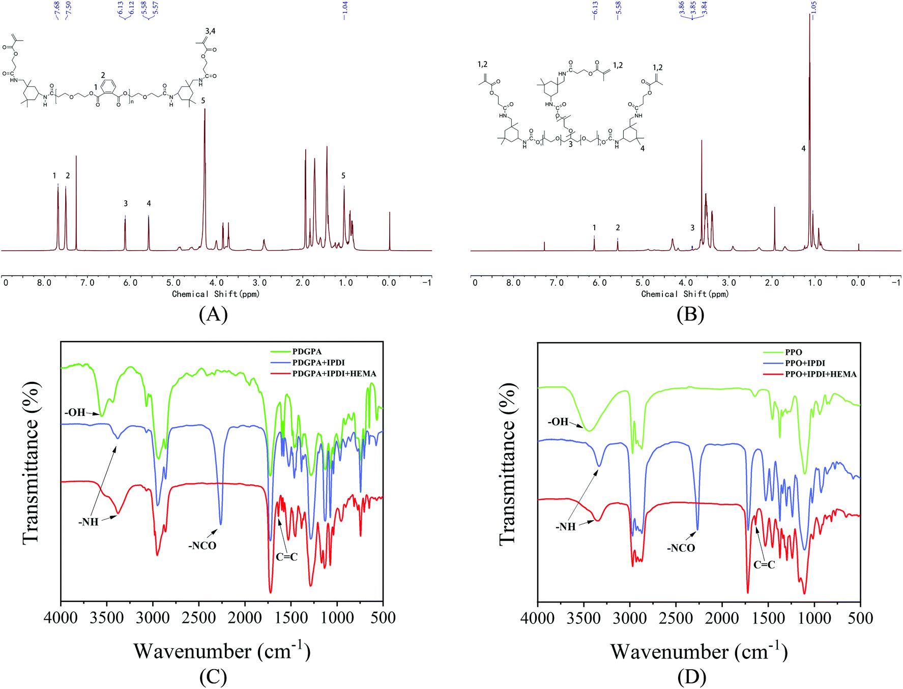
| | Fig. 1 (A) 1H NMR spectra of PU based on polyester polyol. (B) 1H NMR spectra of PU based on the polyether polyol. (C) FT-IR spectra of PU based on polyester polyol. (D) FT-IR spectra of PU based on the polyether polyol. | |
Fourier transform infrared spectroscopy (FT-IR) was used to determine the characteristic absorption peaks with wavenumbers in the range of 4000–500 cm−1. The hydrogen spectrum of nuclear magnetic resonance spectrometry (1H NMR) was measured by a Bruker AVANCE 500 MHz III nuclear magnetic resonance instrument.
Tensile strength and elongation at break
PU/TEGDMA (1:1) was prepared from a PU system composed of synthetic polyester polyurethane and polyether polyurethane with different molar ratios (8:2, 6:4, 4:6, 2:8) and the initiator and redox agent of 1% CQ/EDMAB (3:7) + 1% BPO/DHEPT (1:1), which were mixed evenly under dark conditions. The mixture was divided into samples with equal proportions of the two components, A (containing photosensitizer, oxidant) and B (containing reductant).
The prepared PU matrix was filled into a dumbbell mold, covered with polyethylene film, and cured by LED light to prepare specimens for tensile tests. The specimen size was selected according to the standard GB/T 1040-92 test method for the tensile properties of plastics. A universal testing machine (AG-X plus, Japan) with a crosshead speed of 10 mm min−1 was used for the tensile test. After fracture, each sample was measured after 3 min of stabilization. The formulas for calculating the tensile strength (MPa) and elongation at break (%) were as follows:
| Tensile strength (MPa) = Fmax/DH |
| Elongation at break (%) = (C1 − C)/C |
where
Fmax is the maximum load at the breaking point (N);
D is the width of the breaking point (mm);
H is the thickness of the fracture point (mm);
C1 is the length after break (mm); and
C is the original length of the gauge (mm).
General properties
Water sorption and solution. The test pieces for determining water sorption and solution were prepared as above. The standard test pieces (n = 5) were placed in a sealed desiccator with silica gel and stored at 37 °C for 24 h. They were weighed to the nearest 0.1 mg, and the spent desiccant was replaced with new silica gel desiccant. The above steps were repeated until the mass reduction of each sample was no more than 0.1 mg, and the obtained mass was recorded as M1. The volume of the test piece was calculated and recorded as V. The test piece was immersed in deionized water for 7 d. The water was removed and wiped, and the mass was recorded as M2. The above steps were repeated to dry the test piece until the mass was constant, which was recorded as M3. The water sorption (WSP) and water solution (WSL) were calculated by the following formulas:
Contact angle. PU and commercial resin cement were placed in a hollow Teflon mold with a diameter of 15 mm and a thickness of 1 mm according to ISO 4049. Two glass plates were placed on either side after covering the top and bottom with polyethylene film. The specimens were cured for 20 seconds each time. 6 μL of water was added dropwise, and the results were recorded with DataPhysics (OCA 20, Germany). The water contact angle (CA) was measured at room temperature according to the obtained photos (n = 5).
Degree of conversion. A KBr sheet was pressed, and the newly made PU cement and commercial cement were evenly applied in a thin layer on the surface of the KBr sheet with a small brush, after which they were observed and scanned with an FTIR spectrometer with an attenuated total reflection device before and after curing for 20 seconds (n = 5). The internal parameter was the 1608 cm−1 band (phenyl CC bond), and the relative change in the 1637 cm−1 band (CC bond) before and after curing was calculated to determine the degree of conversion (DC). The DC formula is as follows:
| DC (%) = [1 − (A1637/A1608) cured/(A1637/A1608) uncured] × 100% |
where A1637 is the peak area of the methacrylate CC bond at 1637 cm−1 and A1608 is the peak area of the phenyl CC bond at 1608 cm−1.
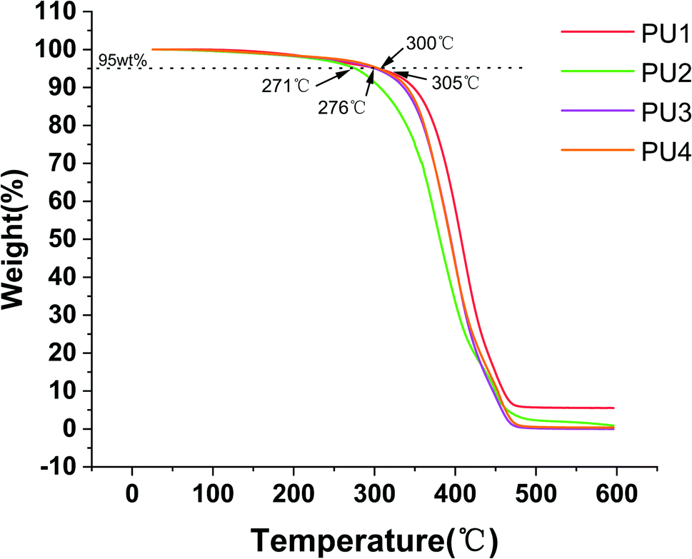
Thermal characterization. The PU matrix was cured for 20 seconds to prepare approximately 5 mg of sample, and the different cements were heated from 0 to 600 °C with a thermal hydrometer to obtain the thermogravimetric curves by a TGA Q500 thermal analyzer. The thermal stability was analyzed at the temperature when the weight loss was 5 wt%.
Mechanical properties
Flexural strength and modulus of elasticity. Commercial cement and PU cement specimens were filled into 2 mm × 2 mm × 25 mm metal molds and cured for 20 seconds according to the ISO 4049 standard. Then, the test pieces were stored in distilled water at 37 °C away from light for 24 h. The flexural strength and elastic modulus of the specimens were evaluated by a universal testing machine with a loading speed of 1 mm min−1 until the specimen broke. The maximum load and slope were recorded, and the flexural strength (FS) and elastic modulus (EM) of the specimen were calculated. The formulas are as follows:
F—maximum load (N); l—distance between supports (mm); b—width of test piece (mm); h—height of test piece (mm); d—the deflection corresponding to F.
Compressive strength. The resin cement was put into a metal mold with a diameter of 4 mm and a height of 6 mm to make the test pieces according to the ISO 9917 standard. The surface and bottom of each test piece were cured for 20 seconds each, stored in distilled water at 37 °C and kept away from light for 24 h. A universal testing machine was used to test the compressive strength by applying a loading speed of 1 mm min−1 until the specimen broke. The maximum load during the fracture process was recorded. The compressive strength (CS) was calculated by the following formula:
F—maximum load; d—diameter of test piece.
Surface hardness. The resin cement was put into a metal mold with a diameter of 6 mm and a height of 2 mm, cured for 20 seconds to prepare a round specimen, and stored in distilled water at 37 °C for 24 h.11 A Vickers hardness indenter was vertically loaded on the surface of the specimen to test the surface hardness of the experimental materials.12 The loading force was 980 mN, and the loading lasted for 10 seconds. The digital display of the hardness value was directly recorded. Each test piece was tested 3 times, and the average value was taken.
Thermal cycling test. Samples for the analysis of flexural strength, compressive strength, tensile strength and surface hardness were alternately placed into 5 and 55 °C water baths and held for 30 seconds each time; this process was repeated 10000 times. The mechanical properties after thermal cycling were calculated according to the corresponding formulas.
Polymerization shrinkage kinetics
A real-time laser ranging system was used to detect the axial shrinkage of the resin cement, and the polymerization shrinkage kinetics were analyzed. Isolated aluminum sheets were placed at the ends on both sides and filled with the resin cement. The laser beam faced the center of the test end after the baffle was carefully removed. The displacement sensor was turned on, and the sample was exposed to light curing for 20 seconds after the cement was stable for 5 min. Data were collected for another 5 min. The shrinkage strain time curve and shrinkage rate time curve were drawn, and the volume shrinkage was calculated according to the following formula, where lin% is the linear shrinkage and vol% is the volume shrinkage:
| vol% = 3lin% − 0.03(lin%)2 + 0.0001(lin%)3 |
Micro-tensile bond strength and fracture mode
Fifty complete fresh isolated molars were provided by the Stomatology Hospital of Jilin University. Each patient signed an informed consent form. The isolated teeth were immersed in 0.5% ammonium chloride solution at 4 °C for storage. First, part of the enamel of the isolated molar crown was cut off with a slow speed saw to expose the dentin. Then, 180, 360 and 600 mesh sandpapers were used to polish an E. max glass–ceramic block under running water for 15 seconds. According to the instructions, HF acid was used to treat the E. max glass–ceramic block for 1 min, and silane coupling agent was lightly applied for 1 min. The isolated teeth and ceramic block were bonded with commercial MS and experimental PU cement, respectively, compressed with 10 N force and cured for 20 seconds. The samples were embedded in epoxy resin and cured. Then, the samples were cut into 1 mm × 1 mm × 8 mm sections along the long axis of the tooth perpendicular to the bonding surface with a slow speed saw. The specimens were randomly divided into two groups according to the different cement bonding groups. One group was immediately tested with a universal testing machine. The other group was subjected to a thermal cycling aging test, and the micro-tensile bond strength was evaluated. The tensile strength (MPA) was calculated as follows:
| micro-tensile strength (MPa) = Fmax/S |
where Fmax is the maximum load at the breaking point (N) and S is the cross-sectional area of the breaking point (mm2).
The fracture surface was observed with a stereomicroscope (×40 magnification) and classified according to the following three fracture modes: (1) bonding interfacial fracture, (2) cohesive fracture (containing glass ceramics, resin cement or dentin), and (3) mixed fracture, i.e., partial interfacial fracture and partial cohesive fracture.
Some immediate and aged specimens were dehydrated with an ethanol gradient, dried thoroughly and sprayed with gold. The morphology of the bonding surface was observed under scanning electron microscopy (SEM). Rhodamine B (RB, 0.1 wt%) was evenly mixed into the resin cement, and the bonding specimen was made according to the previous method for specimens for micro-tensile bond strength tests. The bonding interfacial morphology was observed directly under confocal laser scanning microscopy (CLSM).
Margin microleakage
The isolated molars were collected as described above and prepared to MOD type, with a depth of 3 mm and a width of 4 mm at the isthmus. E. max glass–ceramic inlays were prepared and treated with HF and silane coupling agent. Then, the inlays were bonded to dentin with resin cement after curing for 20 seconds. The test pieces were stored in deionized water at 37 °C for 24 h. The specimens were subjected to cold and hot circulation (5 °C water bath for 30 seconds, 55 °C water bath for 30 seconds) 10000 times. After that, the apical holes were closed with self-curing plastic, and quick-drying nail polish was applied on the detached teeth 1 mm away from the inlay bonding line. The dried teeth were immersed in 1% methylene blue solution for 24 h. The specimens were washed with running water for 15 min to remove the excess dye and cut into 1 mm thin slices along the long axis of the tooth with a slow speed saw. Photos were taken using a stereomicroscope, the dye along the cavity wall was measured using image analysis software (KS 400 image for Windows; Carl Zeiss Ag), and the dye penetration depth was calculated.
Cytotoxicity test
CCK-8 assay. L929 cells in the logarithmic growth stage were inoculated into 96-well plates and co-cultured with matrix extracts for 24 h, 48 h and 72 h. Then, 10 μL of cell counting kit-8 (CCK-8) solution was added to each well and incubated at 37 °C 37 and 5% CO2 in an incubator for 1.5–2 h. The absorbance value of each well plate at a wavelength of 450 nm was measured by a microplate reader, and the relative growth rate (RGR) was calculated. The formula was as follows:
where As is the absorbance of the experimental well and Ac is the absorbance of the control well.
Live/dead cell staining. The above logarithmic L929 cells were inoculated into 6-well plates. The extraction solution was changed after culturing for 24–48 h. The blank control group was replaced with fresh culture medium for 24 h. The live/dead cells were stained with calcein acetoxymethyl ester (calcein AM) and propidium iodide (PI) under dark conditions. After 15 min, the cell morphology was observed under an inverted fluorescence microscope and photographed. Finally, ImageJ software was used to analyze the proportion of living cells, which was consistent with the experimental results of the CCK-8 assay.
Statistics
The normal distribution and variance were assessed by the Kolmogorov–Smirnov test and Bartlett test, respectively. SPSS 19.0 software was used for statistical analysis of the experimental results. The data were analyzed with one-way ANOVA by SPSS 19.0 software, and multiple comparisons were performed using Tukey's test and Dunnett's T3 test. The significance level was set at p = 0.05.
Results and discussion
PU characterization
The main reaction processes of PU are based on polyester polyols and polyether polyols (Appendix Fig. 1). The 1H NMR and FT-IR (Fig. 1) results proved that PU was successfully synthesized. Fig. 1(A) and (B) showed that polyester and polyether polyols reacted with isophorone diisocyanate in turn to form NCO-terminated prepolymers, and then HEMA was added to obtain acrylate-modified polyester PU. After the addition of isophorone diisocyanate, the NCO vibration peak was observed at 2260 cm−1. The NCO group reacted with the hydroxyl group to form the N–H peak in the carbamate bond (–NHCOO–) at 3340 cm−1. When the HEMA reaction was complete, the CC absorption peak was observed at 1638 cm−1, and the 2260 cm−1 NCO vibration peak decreased and disappeared, which confirmed the end of the reaction.
Fig. 1(C) and (D) show the 1H NMR spectra of the polyester and polyether PU products, respectively. The proton peak of IPDI was at 1.04 ppm. The free terminal double-bond proton peaks of HEMA were at 5.57–5.58 ppm and 6.12–6.13 ppm, and the benzene ring proton peak was at 7.50–7.68 ppm. Therefore, FT-IR and 1H NMR analyses proved that the polyester polyether PU was successfully synthesized.
Tensile strength and fracture toughness
As mature technology for elastic buffer materials, PU is widely used in various fields, but unmodified PU has limited performance in applications where they undergo dental maxillary force and aging in the presence of saliva. In contrast, mixtures of polyester and polyether components enables the realization of complementary advantages to enhance the comprehensive performance of PU.13 Because polyester is more rigid and polyether is more flexible, these components can be mixed in different ratios to obtain suitable tensile strength and elongation at break, which can buffer the residual stress caused by polymerization shrinkage.14 Fig. 2 showed the effect of different polyester:polyether ratios on the tensile and elongation properties of PUs. With a decrease in the ester–ether ratio, the tensile strength decreased (28.37–21.85 MPa) (p < 0.05), while the elongation at break increased (24.75–58.38%) (p < 0.05). These opposite trends made it difficult to simultaneously optimize both characteristics.
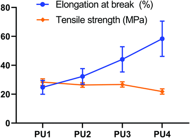 |
| | Fig. 2 Tensile testing. Tensile strength and elongation at break for PUs with different molar ratios of PDGPA to PPO that could be suitable for application in dental cements. | |
Upon increasing the polyether content, the polyester and polyether mixed and dissolved more completely, which reduced phase separation and enhanced the density of the network structure. An increased polyether content not only can achieve toughening but also not reduce the cross-linking density of PU too much. Polyester polyurethanes had great cohesive energy and strong rigidity, and the addition of a benzene ring improves its mechanical properties. When the ratio of ester to ether was higher, the soft segments of polyester gradually dispersed among the soft segments of polyether, and strong polar ester bonds penetrated the lattice of molecular chain segments, resulting in enhanced hydrogen bonding between molecules. Thus, the tensile strength of the PU system was improved. The elongation at break of polyether was better than that of polyester. When the ester:ether ratio was relatively low, polyether could obtain good elongation at break due to the large number of soft segments in the system and the deformation of ether bonds that easily rotated, which cushion the residual tensile stress generated during the reduction in polymerization shrinkage and mitigate unbalanced damage of the interface under the effect of integrated stress.15
General properties
Resin materials are prone to water absorption and dissolution in the oral environment, resulting in the degradation of material properties. Therefore, it is important to maintain the hydrophobicity of the materials to ensure that they do not easily dissolve and keep the bonding interface stable.16,17 A preliminary study by this group found that among the self-adhesive resin cements Clearfil SA, MS and Rely X Unicem, MS had good physical and chemical properties and the best bonding and aging performance. Furthermore, a large amount of 10-MDP can enhance the interfacial bonding performance of MS to levels close to the experimental group.18 Therefore, MS was selected as the commercial control group to evaluate the performance of the new cement in this study. For the newly synthesized PU cement, ester bonds were easily hydrolyzed and had poor stability in liquid environments. The polyether component, however, resisted hydrolysis and could improve the resistance to aging of the system. As shown in Fig. 3(A) and (B), the water absorption value of the new PU cement mixed with polyester and polyether increased with increasing proportion of polyether in the composition; PU4 had the highest value (p < 0.05). No significant difference in the dissolution value was observed among the PU groups (p > 0.05). The values of these parameters were significantly lower than those of the commercial group (p < 0.05), indicating that the new PU cement had good hydrolytic stability. Fig. 3(C) showed that the water contact angles of the experimental groups after curing gradually decreased with increasing polyether content, but all the values were greater than 90°, which showed hydrophobicity and verified that the water absorption capacity of the polyester components was weaker than that of polyether components.19 Furthermore, compared with hydrophilic commercial cement (71.40° ± 3.54°), the experimental materials were more conducive to resisting the invasion of water from the environment.
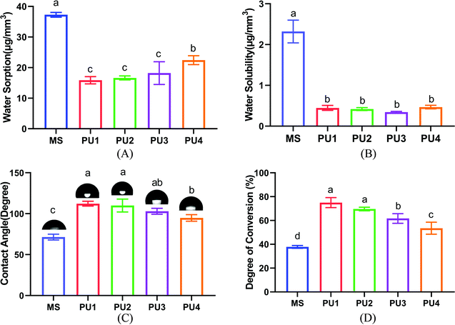 |
| | Fig. 3 Characterization of the PU and MS cements. (A) Water sorption. (B) Water solubility. (C) Contact angle of five different cements and representative images of the cement surface. (D) Influence of different PUs on the degree of conversion of the experimental and commercial cements (mean ± SD, n = 5). | |
DC is an important index used to evaluate the polymerization ability of polymer materials.20 Fig. 3(D) showed that the DC of PU decreased with increasing polyether composition. Moreover, the average DC values of the experimental group (74.99%, 69.61%, 61.7%, 53.47%) were much greater than those of the commercial group (37.82%). This showed that with an increase in polyether components, polyether with three functional groups formed a dense cross-linked network, which increased constraints on chain segments and thus slowed the progress of the reaction and ultimately decreased the DC level of the PU4 group with more polyether components. With the higher DC, more molecules cross-linked into a dense network structure, which not only enhanced mechanical properties such as strength and hardness but also reduced water absorption, swelling and dissolution.21,22 Additionally, the polymerization reaction proceeded more completely, and the residual unreacted monomers greatly decreased, which prevented dissolution of material and damage due to monomer precipitation as well as cytotoxicity to organisms; this increased the biosafety of the material and enhanced the stability of the interfacial bonding.23
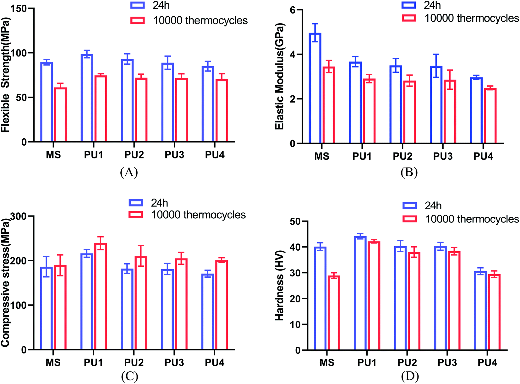
Modifying the ratio of polyester to polyether not only affected water absorption and solubility but also had a great impact on the crystallinity, thermal stability and mechanical strength of the material.24–26 The mechanical strength and thermal stability could be improved by hard segments. The temperature corresponding to 5% mass loss in the experimental group was more than 271 °C, which indicated that the materials could remain stable in the oral environment (5–55 °C) (Fig. 4A). The thermal stability, flexural strength, elastic modulus, compressive strength and surface hardness of the cement gradually increased (Fig. 4, 5 and Table 2) with increasing polyester content.27 The values were close to or better than those of the commercial group, which confirmed that the new PU resin cement could resist the effect of oral masticatory stress, was less prone to internal damage and fracture than the commercial material, and improved the durability of the cement.
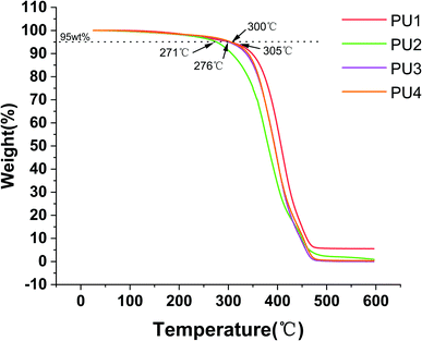 |
| | Fig. 4 Thermal characterization of four kinds of PUs. | |
 |
| | Fig. 5 Mechanical properties of the cements after 24 h and 10000 thermocycles. (A) Flexible strength (B) elastic modulus (C) compressive strength (D) hardness (mean ± SD, n = 8). | |
Table 2 Mechanical properties of the cements after 24 h and 10000 thermocyclesa
| Mechanical property |
|
MS |
PU1 |
PU2 |
PU3 |
PU4 |
| Capital letters represent statistically significant differences within each cement group (p < 0.05; horizontal comparisons). Lowercase letters represent statistically significant differences within each cement group before and after 10000 thermocycles (p < 0.05; vertical comparisons). 24 h, 24 hours group. 10000, 10000 thermocycle group. Data are expressed as the mean (standard deviation, SD). |
| Flexible strength (MPa) |
24 h |
89.41 (3.00)Aa |
98.66 (4.18)Ba |
93.12 (5.84)ABa |
88.97 (7.39)Aa |
85.04 (5.43)Aa |
| 10000 |
31.14 (4.72)Ab |
74.64 (1.91)Bb |
72.05 (4.06)Bb |
71.68 (4.80)Bb |
70.25 (6.36)Bb |
| Elastic modulus (GPa) |
24 h |
4.97 (0.40)Aa |
3.67 (0.23)Ba |
3.50 (0.31)BCa |
3.48 (0.52)BCa |
2.97 (0.09)Ca |
| 10000 |
3.45 (0.27)Ab |
2.91 (0.18)Bb |
2.82 (0.25)Bb |
2.86 (0.43)Bb |
2.49 (0.09)Ba |
| Compressive strength (MPa) |
24 h |
186.46 (22.8)Aa |
216.29 (8.58)Ba |
182.15 (10.72)Aa |
181.19 (12.43)Aa |
170.84 (7.65)Aa |
| 10000 |
189.56 (23.43)Aa |
239.13 (14.53) Ba |
210.79 (23.22)ABa |
205.16 (13.39) Aa |
201.45 (5.09)Ab |
| Hardness (HV) |
24 h |
40.16 (1.50)Aa |
44.21 (1.05)Ba |
40.35 (2.13)Aa |
40.27 (1.50)Aa |
30.62 (1.32)Ca |
| 10000 |
28.93 (1.08)Ab |
42.20 (0.65)Ba |
38.06 (2.01)Ca |
38.38 (1.45)Ca |
29.47 (1.27)Aa |
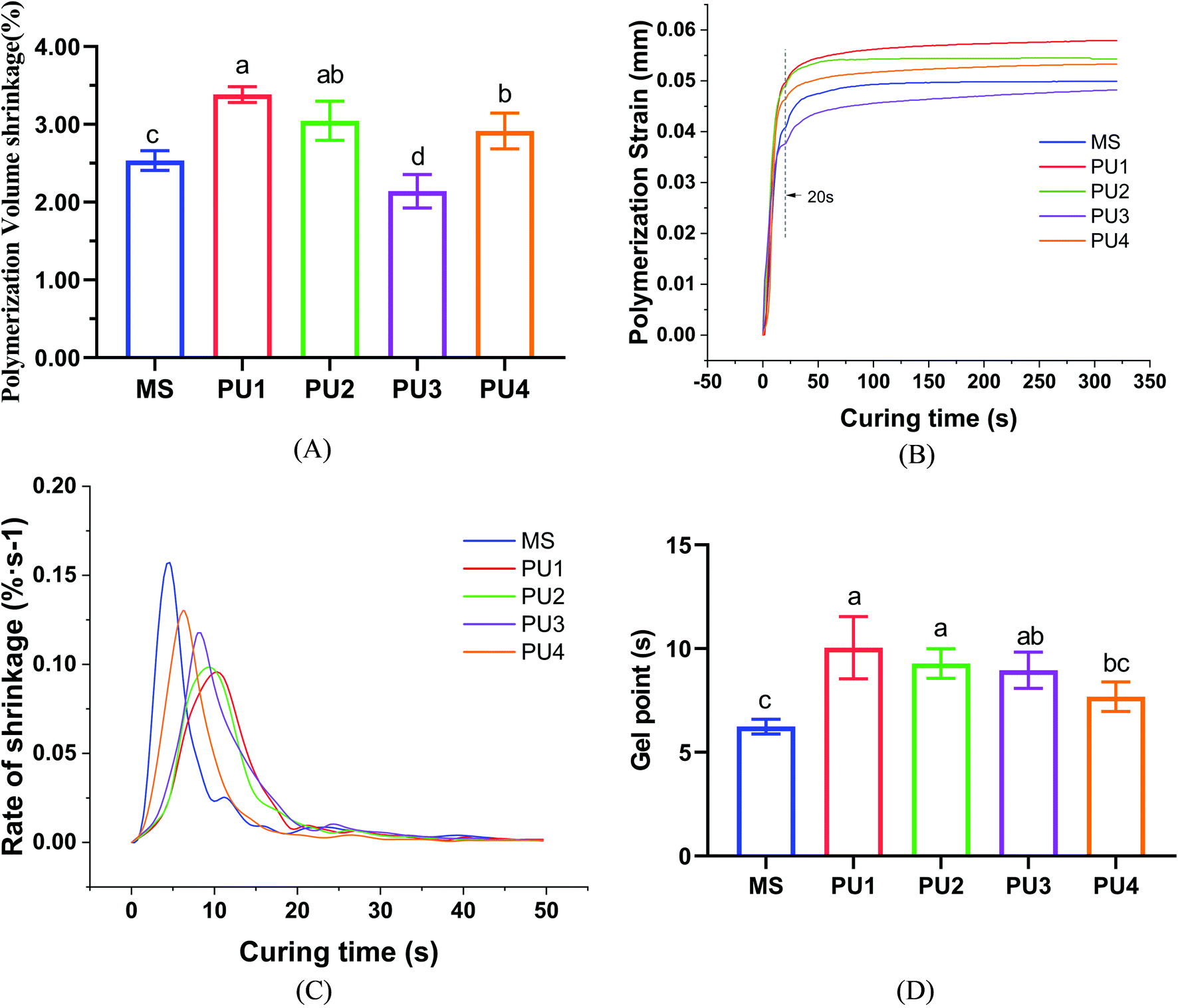
Polymerization shrinkage
In addition to the properties of the material, the durability of the bonding interface is affected by polymerization shrinkage, bond strength and interface aging.28 To reduce the adverse effects of polymerization shrinkage, high molecular weight PU materials were chosen to reduce the concentration of double bonds and the number of double-bond reactions, while the volume polymerization shrinkage was compensated for by intermolecular and intramolecular elastic feedback with different proportions of soft and hard segment molecular chains.
At the beginning of polymerization, the viscosity of the system is low, and the cement can flow freely to compensate for the polymerization shrinkage stress. When approaching the gel point, the viscosity of the system increases, and a “gel phenomenon” appears. At this time, the elastic modulus and the shrinkage stress are low, and the molecular chains could move and deform to release stress. It has been speculated that delaying the gel stage and increasing the buffer time can better reduce the strain caused by polymerization shrinkage.29–31 With the progression of the reaction, the DC and viscosity increase. When molecular movement and diffusion are restricted by the viscosity of the system, the reaction slows automatically until it stops, and polymerization stress is generated rapidly. According to previous studies, polymerization shrinkage was directly related to DC.32 The higher DC was, the more molecules underwent bonding reactions, which led to more shrinkage of molecular spacing and larger volume shrinkage of the polymer. According to the DC (Fig. 4D) and polymerization shrinkage results (Fig. 6A), the MS group reacted fastest and ended soonest, with the lowest DC (37.82% ± 1.17%); thus, less polymerization shrinkage occurred (2.54% ± 0.11%). The PU1 group showed the slowest reaction speed (Fig. 6C) and the most delayed gel point (Fig. 6 D), leading to the corresponding largest DC value (74.99% ± 4.19%). Although the time and degree of polymerization shrinkage were improved by molecular chain buffering, it was still difficult to compensate for the volume shrinkage due to the large number of double-bond reactions. In the end, the polymerization shrinkage was also greatest (3.38% ± 0.09%). There was still a certain potential for sliding between chain polyester and network polyether molecules due to the moderate ester:ether ratio of the PU3 group, which could reduce the polymerization shrinkage. The delayed gel point gave PU3 more time than PU4 to cushion shrinkage deformation. Therefore, the polymerization shrinkage rate (2.14% ± 0.19%) was the smallest (p < 0.05), which resulted in good elastic buffer properties. The first null hypothesis was rejected.
 |
| | Fig. 6 Polymerization shrinkage and kinetics of the resin cements: (A) polymerization volume shrinkage, (B) polymerization strain, (C) rate of shrinkage, and (D) gel point (mean ± SD, n = 5). | |
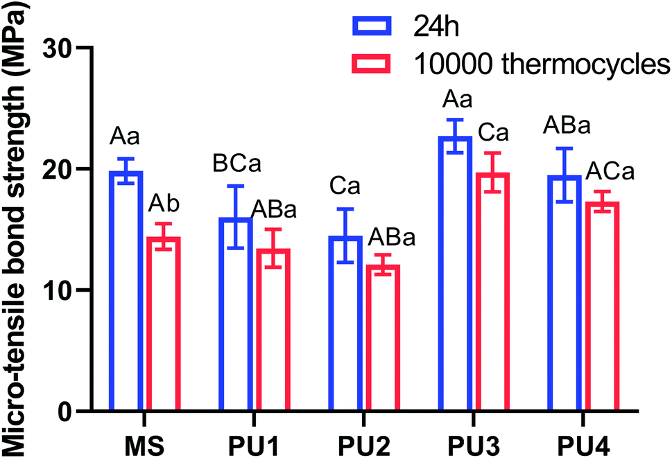
Bond strength
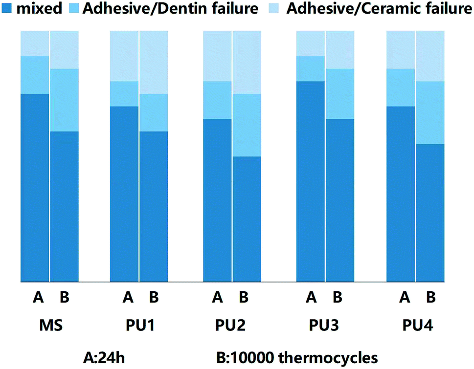
Great bonding ability is a prerequisite for maintaining stable interfacial bonding. Fig. 7 shows that the bonding interface had a uniform texture and good continuity, according to the SEM and CLSM results. Only a few short resin tags were observed at the fracture interface, indicating that the bonding of self-adhesive resin cement did not rely on the mechanical chimerism of the resin tag. PU has high viscosity, and urethane bonds that enhance the bond strength and cohesion of the cement.33,34 Ester groups were polar groups that easily form many hydrogen bonds with the bonding interface, which enhanced the bond between PU cement and the interface.35,36 In addition, 10-MDP (acid monomer) was added to modify the hybrid layer through phosphoric acid etching and slight demineralization. Phosphoric acid groups can chelate with Ca+ to form a stable chemical connection and enhance the bonding efficiency.37,38 Fig. 8 demonstrated that the bond strength of resin cement was enhanced in segments with increased polyester content, but the bond strength of the PU3 group was the greatest and close to that of the MS commercial group (p > 0.05). The ester and ether components of the PU3 group were well mixed, the dissolution and distribution of soft and hard segments were uniform, and microphase separation was not significant. PU3 not only had sufficient fluidity to infiltrate the bonding surface (compared to PU1 and PU2) but also enabled urethane bond formation. Moreover, the polyether network was moderately cross-linked (compared to PU4) and did not excessively restrict the flow of 10-MDP, which resulted in bonding and cross-linking and thus showed the best bonding performance. The fracture modes of the interfaces in Fig. 9 showed that the mixed fractures in both the commercial group and the experimental group mainly involved interfacial fracture, which indicated that the interfacial bond strength was equivalent to the cohesive strength and that the bonding interface was relatively balanced and stable. Therefore, the second null hypothesis was rejected.
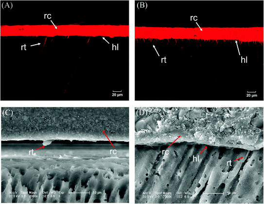 |
| | Fig. 7 Representative images of (A), (B) CLSM and (C), (D) SEM showing the interfacial characteristics; comparatively few short resin tags (rt) underneath the hybrid layer (hl) are well defined. rc, resin cement; rt, resin tag; hl, hybrid layer. | |
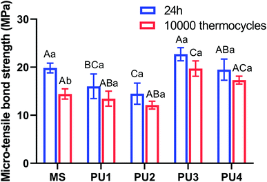 |
| | Fig. 8 Microtensile strength of PUs and MS after 24 h and 10000 thermocycles. Different capital letters represent statistically significant differences within each cement group (p < 0.05; horizontal comparisons). Lowercase letters represent statistically significant differences within each cement group before and after 10000 thermocycles (p < 0.05; vertical comparisons) (mean ± SD, n = 20). | |
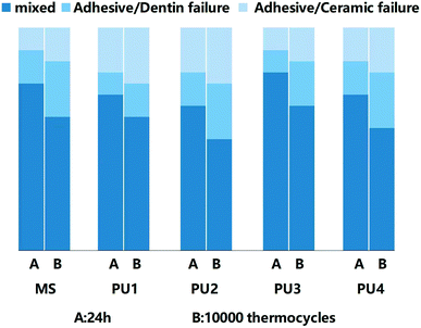 |
| | Fig. 9 Distribution of three fracture modes after 24 h and 10000 thermocycles. | |
Aging and microleakage
Dental materials exposed to saliva for a long time are prone to fatigue damage owing to the changing temperature of the environment and the cyclic loading of masticatory forces.39,40 Due to the inconsistency of the thermal expansion coefficient, a micro gap gradually appears between the cement and dentin, which eventually leads to bonding failure. In this experimental group, all the cements showed hydrophobic characteristics, and the hydrolysis resistance of the cements was gradually enhanced with increasing polyether content.
Thus, according to Fig. 6, the flexural strength properties of the experimental group decreased by approximately 17.39–24.34%, the elastic modulus decreased by approximately 15.98–20.75%, the compressive strength increased by approximately 10.56–17.91%, and the surface hardness decreased by 3.75–5.67%. These values were much lower than those of the commercial control group after aging (31.62%, 30.51%, 1.66%, and 27.98%, respectively), which were equivalent to those before aging; this indicated that the cement in the experimental group maintained great mechanical properties after aging. The excellent tensile properties of the experimental group, especially the PU3 group (Fig. 2), could compensate for the stress caused by differences in thermal expansion of the interface and maintain the stability of the bonding interface. The immediate bond performance of the experimental group was close to that of the commercial control group (Fig. 8) and better than that of the other PU groups. The decline in bond strength after aging was smaller in the experimental group than the commercial group; therefore, the bond strength after aging was much higher than that of the commercial group.
The bond strength of the cement decreased to less than 20 MPa after the thermal cycling test.41 Due to the obvious aging of the dentin interface, the 10-MDP, silane coupling agent and other components that increased the interfacial adhesion appeared hydrolyzed. Therefore, many interfacial bonding failures occurred, and the proportion of mixed fractures decreased.
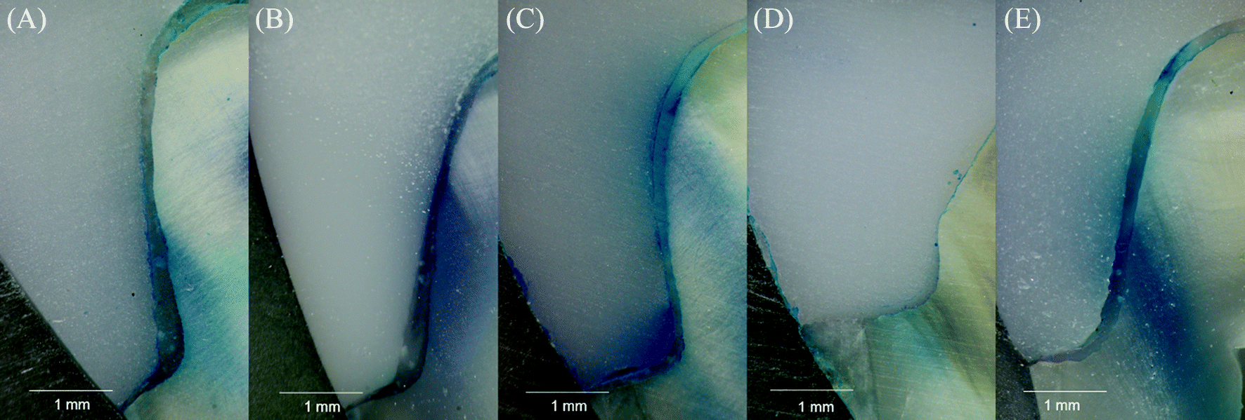
In conclusion, the experimental group resisted aging erosion and maintained the stability of the bonding interface. Fig. 10 showed the marginal microleakage after aging in each group. The microleakage after aging was more obvious in the PU2 group and reached the essential deep layer (3.48 ± 0.40 mm), while less microleakage occurred in the PU3 group and ended only at the gingival wall (1.39 ± 0.35 mm). It may have been that the adhesive force of PU2 was relatively weak, the polymerization shrinkage was large, and the bonding interface was more easily damaged after aging, which resulted in more marginal microleakage. The polymerization shrinkage, micro-tensile strength and aging resistance of the PU3 group were close to or better than those of the commercial MS group, so the microleakage was the least. The above results proved that PU3 cement reduced the degree of microleakage at the margin and improved the durability and stability of the prosthesis. In conclusion, the third null hypothesis was rejected (Table 3).
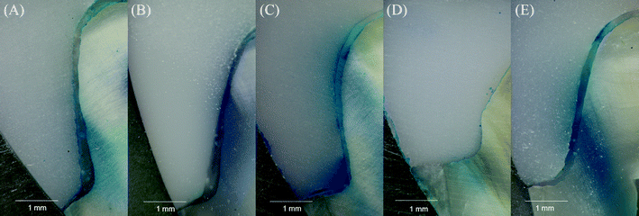 |
| | Fig. 10 Representative microleakage images between the tooth and ceramic inlay after 10000 thermocycles. (A) MS; (B) PU1; (C) PU2; (D) PU3; (E) PU4. | |
Table 3 Microleakage depths (mm) at the margins measured using microscopya
| Cement |
MS |
PU1 |
PU2 |
PU3 |
PU4 |
| Depths (mm) of microleakage between the tooth and ceramic inlay after 10000 thermocycles were obtained from images. (A) MS; (B) PU1; (C) PU2; (D) PU3; (E) PU4. Data are expressed as the mean (SD). Dissimilar letters indicate values that are significantly different from each other (p < 0.05). |
| Depth (mm) |
2.03 (0.16)bc |
2.59 (0.43)b |
3.48 (0.40)a |
1.39 (0.35)c |
2.39 (0.37)b |
Cytotoxic and live/dead staining
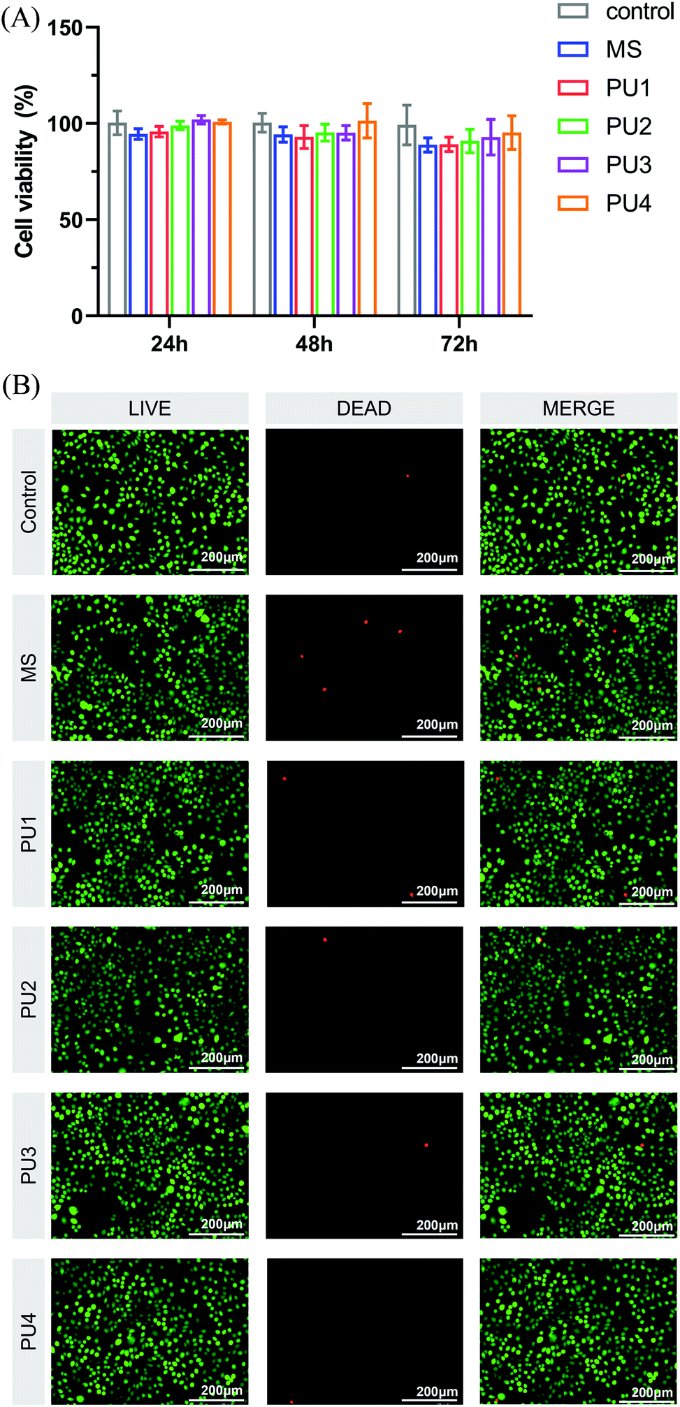
As a dental material, the new cement must have good biocompatibility in addition to ensuring good bonding properties and interfacial stability.42 The cytotoxicity of the new cement was evaluated by the changes in L929 cell activity and morphology. As shown in Fig. 11(A), there was no significant difference in cell proliferation activity between the experimental group and the blank control and no significant difference between the PU and MS groups. The relative survival rate of cells corresponding to each group of cement was greater than 75%, which can be considered nontoxic.43 The results of live/dead cell staining were shown in Fig. 11(B). The morphology of L929 cells became longer and slightly shuttle-shaped, which was similar to the morphology of fibroblasts in the blank control group, with more uniform cell distribution. ImageJ software was used to count the proportions of living and dead cells, and the results were basically consistent with those of the CCK-8 assay. These results showed that the experimental group exhibited great biocompatibility, which established a safe foundation for application in the oral environment.
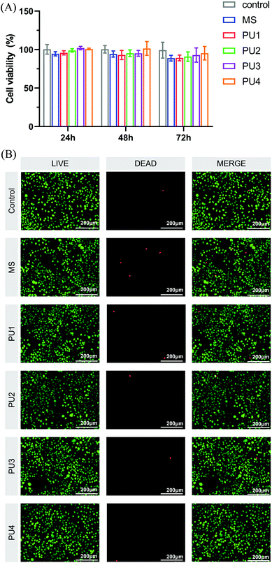 |
| | Fig. 11 (A) Cytotoxicity of the control, MS and PU cements in different dilutions with culture medium at 24 h, 48 h, and 72 h determined by CCK-8 assay. The RGR was calculated. (B) Live/dead fluorescence cell staining after L929 cells were cultured for 24 h in culture medium with the control, MS and PUs. Living cells were stained with calcium-AM (green), and dead cells were stained with PI (red). | |
Conclusions
In summary, this research group prepared a new generation of cement with a light-curing functionality, combinations of soft and hard segments and the ability to buffer polymerization shrinkage stress by using the characteristics of polyester and polyether polyurethane. The developed cement possessed good bonding performance, small polymerization shrinkage, hydrophobicity, low solubility, and great aging resistance, which ensured the permanent stability of the bonding interface and laid the foundation for the application of PU cement in dentistry.
Author contributions
Xi He, contributed to conception, design, data acquisition, and interpretation, drafted and critically revised the manuscript; Shiyang Yu, contributed to data interpretation, drafted and critically revised the manuscript; Huimin Wang, Zilu Tian, Haihuan Gong, Ying Zhao, contributed to data analysis and critically revised the manuscript; Jiahui Zhang, contributed to drafted, data acquisition and critically revised the manuscript; Song Zhu, Zuosen Shi, Zhanchen Cui, contributed to data conception and design, drafted and critically revised the manuscript. All authors gave final approval and agreed to be accountable for all aspects of the study.
Conflicts of interest
There are no conflicts to declare.
Acknowledgements
This research was financially supported by the Science and Technology Project of Jilin Provincial Department of Finance (jcsz2020304-17), the Science and Technology Project of Jilin Provincial Department of Education (JJKH20221094KJ), and the National Natural Science Foundation of China (NSFC, Grant No. 82071163).
Notes and references
- T. Beazoglou, S. Eklund, D. Heffley, J. Meiers, L. J. Brown and H. Bailit, Public Health Rep., 2007, 122, 657–663 CrossRef PubMed.
- C. Signori, T. Gimenez, F. M. Mendes, M. Huysmans, N. J. M. Opdam and M. S. Cenci, J. Dent, 2018, 75, 22–33 CrossRef PubMed.
- R. L. Sakaguchi, Dent. Mater., 2005, 21, 3–6 CrossRef PubMed.
- A. R. Curtis, W. M. Palin, G. J. Fleming, A. C. Shortall and P. M. Marquis, Dent. Mater., 2009, 25, 188–197 CrossRef CAS PubMed.
- L. D. Randolph, W. M. Palin, G. Leloup and J. G. Leprince, Dent. Mater., 2016, 32, 1586 CrossRef CAS PubMed.
- A. Bacchi, M. Nelson and C. S. Pfeifer, Dent. Mater., 2016, 32, 233–239 CrossRef CAS PubMed.
- A. Bacchi and C. S. Pfeifer, Dent. Mater., 2016, 32, 978–986 CrossRef CAS PubMed.
- J. D. Galligan, A. M. Schwartz and F. W. Minor, J. Dent. Res., 1968, 47, 629–632 CrossRef CAS PubMed.
- H. Gong, X. Guo, D. Cao, P. Gao, D. Feng, X. Zhang, Z. Shi, Y. Zhang, S. Zhu and Z. Cui, J. Mater. Chem. B, 2019, 7, 744–754 RSC.
- X. Guo, Q. Cheng, H. Wang, G. Yu, Z. Tian, Z. Shi, Z. Cui and S. Zhu, Eur. J. Oral Sci., 2020, 128, 89–99 CrossRef CAS PubMed.
- S. A. Shahdad, J. F. McCabe, S. Bull, S. Rusby and R. W. Wassell, Dent. Mater., 2007, 23, 1079–1085 CrossRef CAS PubMed.
- S. Saber-Samandari and K. A. Gross, J. Eur. Ceram. Soc., 2009, 29, 2461–2467 CrossRef CAS.
- M. Charlon, B. Heinrich, Y. Matter, E. Couzigné, B. Donnio and L. Avérous, Eur. Ploym. J., 2014, 61, 197–205 CrossRef CAS.
- A. Domanska and A. Boczkowska, Polym. Degrad. Stab., 2014, 108, 175–181 CrossRef CAS.
- J. O. Akindoyo, M. Beg, S. Ghazali, M. Islam, N. Jeyaratnam and A. J. Yuvaraj, RSC Adv., 2016, 6, 114453–114482 RSC.
- V. Mucci, G. Arenas, R. Duchowicz, W. D. Cook and C. Vallo, Dent. Mater., 2009, 25, 103–114 CrossRef CAS PubMed.
- B. Howard, N. D. Wilson, S. M. Newman, C. S. Pfeifer and J. W. Stansbury, Acta Biomater., 2010, 6, 2053–2059 CrossRef CAS PubMed.
- X. Liu, H. Wang, S. Yu, Q. Zhao, Z. Shi, Z. Cui and S. Zhu, RSC Adv., 2020, 10, 32476–32484 RSC.
- Z. M. Wright, B. D. Holt and S. A. Sydlik, J. Mater. Chem. B, 2017, 5, 7743–7755 RSC.
- J. G. Leprince, W. M. Palin, M. A. Hadis, J. Devaux and G. Leloup, Dent. Mater., 2013, 29, 139–156 CrossRef CAS PubMed.
- C. N. Carvalho, M. D. S. Lanza, L. G. Dourado, E. M. Carvalho and J. Bauer, Int. J. Dent., 2019, 2019, 5496784 Search PubMed.
- A. D. Loguercio, I. Luque-Martinez, M. A. Muñoz, A. L. Szesz, J. Cuadros-Sánchez and A. Reis, Oper. Dent, 2014, 39, 652–662 CrossRef CAS PubMed.
- J. Ge, M. Trujillo and J. Stansbury, Dent. Mater., 2005, 21, 1163–1169 CrossRef CAS PubMed.
- E. N. Guseva, A. S. Sakhatskii and V. V. Zuev, Fuller. Nanotub. Car. N., 2018, 1–28 Search PubMed.
- I. Yilgor, W. Yilgor and G. L. Wilkes, Polymers, 2015, 58, A1–A36 CrossRef CAS.
- P. Pissis, A. Kanapitsas, Y. V. Savelyev, E. R. Akhranovich, E. G. Privalko, V. P. Privalko, P. Pissis, A. Kanapitsas and E. R. Akhranovich, Polymers, 1998, 39, 3431–3435 CrossRef CAS.
- A. Alkhtib, D. J. Manton, M. F. Burrow, S. Saber-Samandari, J. E. Palamara, K. A. Gross and E. C. Reynolds, J. Investig. Clin. Dent., 2013, 4, 94–100 CrossRef PubMed.
- L. Boaro, W. C. Brandt, J. Meira, F. P. Rodrigues, W. M. Palin and R. R. Braga, J. Dent., 2014, 42, 140–148 CrossRef CAS PubMed.
- M. Atai, D. C. Watts and Z. Atai, Biomaterials, 2005, 26, 5015–5020 CrossRef CAS PubMed.
- D. A. Abu-elenain, S. H. Lewis and J. W. Stansbury, Dent. Mater., 2013, 29, 1173–1181 CrossRef CAS PubMed.
- L. C. Boaro, F. Gonçalves, T. C. Guimarães, J. L. Ferracane, C. S. Pfeifer and R. R. Braga, Dent. Mater., 2013, 29, 398–404 CrossRef CAS PubMed.
- C. S. Pfeifer, J. L. Ferracane, R. L. Sakaguchi and R. R. Braga, J. Dent. Res., 2008, 87, 1043–1047 CrossRef CAS PubMed.
- X. H. Kong, G. G. Liu and J. M. Curtis, Eur. Polym. J., 2012, 48, 2097–2106 CrossRef CAS.
- I. Mihail, Rapra Technology, 2005.
- L. S. Nair and C. T. Laurencin, Prog. Polym. Sci., 2007, 32, 762–798 CrossRef CAS.
- M. Araujo, S. V. Vlierberghe, J. Feiteira, G. J. Graulus, K. V. Tittelboom, J. C. Martins, P. Dubruel and N. D. Belie, Mater. Des., 2016, 98, 215–222 CrossRef CAS.
- L. Mair and P. Padipatvuthikul, Dent. Mater., 2010, 26, e17–23 CrossRef PubMed.
- E. Papia, C. Larsson, M. du Toit and P. Vult von Steyern, J. Biomed. Mater. Res., Part B, 2014, 102, 395–413 CrossRef PubMed.
- S. Al-Saleh, T. W. Aboghosh, M. S. Hazazi, K. A. Binsaeed, A. M. Almuhaisen, H. I. Tulbah, A. S. Al-Qahtani, S. Shabib, M. Binhasan, F. Vohra and T. Abduljabbar, Polymers, 2021, 13, 4227 CrossRef CAS PubMed.
- M. Schmid-Schwap, A. Graf, A. Preinerstorfer, D. C. Watts, E. Piehslinger and A. Schedle, Dent. Mater., 2011, 27, 855–869 CrossRef CAS PubMed.
- S. S. Scherrer, P. F. Cesar and M. V. Swain, Dent. Mater., 2010, 26, e78–93 CrossRef PubMed.
- K. Landuyt, T. Nawrot, B. Geebelen, J. D. Munck, J. Snauwaert, K. Yoshihara, H. Scheers, L. Godderis, P. Hoet and B. V. Meerbeek, Dent. Mater., 2011, 27, 723–747 CrossRef PubMed.
- D. Cao, Y. Zhang, Y. Li, X. Shi, H. Gong, D. Feng, X. Guo, Z. Shi, S. Zhu and Z. Cui, Mater. Sci. Eng., C, 2017, 78, 333–340 CrossRef CAS PubMed.
|
| This journal is © The Royal Society of Chemistry 2022 |
Click here to see how this site uses Cookies. View our privacy policy here. 
 Open Access Article
 This Open Access Article is licensed under a Creative Commons Attribution-Non Commercial 3.0 Unported Licence
 a,
Shiyang Yua,
Huimin Wanga,
Zilu Tiana,
Jiahui Zhang
a,
Shiyang Yua,
Huimin Wanga,
Zilu Tiana,
Jiahui Zhang