
 Open Access Article
 This Open Access Article is licensed under a Creative Commons Attribution-Non Commercial 3.0 Unported Licence
Chemical looping steam reforming of glycerol for hydrogen production over NiO–Fe2O3/Al2O3 oxygen carriers†
Hetong Li ,
Yuchun Zhang*,
Peng Fu*,
Ranran Wei,
Zhiyu Li,
Lei Dai and
Andong Zhang
,
Yuchun Zhang*,
Peng Fu*,
Ranran Wei,
Zhiyu Li,
Lei Dai and
Andong Zhang
School of Agricultural Engineering and Food Science, Shandong University of Technology, Zibo, 255000, China. E-mail: zhangyc@sdut.edu.cn; fupengsdut@163.com; 17864386052@163.com; 1491696847@qq.com; lizhy@sdut.edu.cn; daileixz@163.com; 936085286@qq.com
First published on 24th August 2022
Abstract
Fe-based oxygen carriers (OCs) are widely used in chemical looping steam reforming (CLSR) due to excellent resistance to carbon buildup, low toxicity, and high activity. In this study, a type of nano NiO–Fe2O3/Al2O3 Fe-based OC that can easily be reduced by fuels and re-oxidized by air was developed for use in glycerol CLSR. It was synthesized by co-precipitation and impregnation. Based on the quadratic regression orthogonal model, a quadratic polynomial function was established to investigate the effects of temperature (T), water/carbon ratio (S/C), and loading (M) on hydrogen content (HL) and hydrogen selectivity (S). The OCs were characterized by XRD, XPS, SEM/EDX-mapping, TEM, and H2-TPR to determine their physicochemical properties. XPS shows the Fe phase highly interacted with the Al2O3 supporting matrix by forming Fe aluminates in NiO–Fe2O3/Al2O3. The S (85.33%) and HL (78.41%) were obtained under the optimal conditions T = 600 °C, S/C = 1.0 mol mol−1 and M = 0. A hydrogen content fluctuation within 4% was obtained under T = 700 °C, S/C = 1.0 mol mol−1, and M = 2.5%, which means the cycle stability is perfect because of the addition of Ni. This study provides a basis for the development of efficient oxygen carriers in the CLSR system.
1. Introduction
Biodiesel is a new renewable energy source that can replace traditional fossil energy sources. Biodiesel is mainly made from fatty acids in oil or acidified oil through a catalytic transesterification step.1,2 The by-product crude glycerol is produced in the biodiesel production process and the percentage of crude glycerol reaches 10%. The impurities in crude glycerin are water, organic residues, and ash. It is an oil fuel with poor quality that is difficult to use and handle. Therefore, it is urgent to find an efficient way to utilize crude glycerin. Currently, crude glycerol is utilized in the following ways: purification of crude glycerol to produce pure glycerol,3 microbial fermentation using crude glycerol as a carbon source,4,5 production of high-value chemicals by chemical conversion methods, etc. Some scholars have also studied the aqueous phase reforming of crude glycerol for hydrogen production.6,7 Crude glycerol contains methanol, water, inorganic salts, ash, and other substances. But the purification cost of crude glycerol is high. It is considered that direct chemical conversion of crude glycerol into high-value products has broad application prospects. Among them, chemical looping steam reforming (CLSR) for hydrogen production has received a lot of attention from researchers in recent years due to its low energy consumption, high efficiency, and simple steps.8–10 CLSR is carried out at atmospheric pressure, and it is easier to operate than aqueous phase reforming (APR). The CLSR hydrogen production process differs from the conventional steam reforming (SR) process. It is fed by fuel steam and oxidized by air instead of oxygen. And it cycles between these two steps. Meanwhile, CLSR has lower energy consumption, because it can achieve auto-thermal conditions. The heat released in the oxidation reaction compensates for the heat load on the rest of the reactor. It is suitable for different reactor configurations, among which fixed-bed reactors are widely used for CLSR hydrogen production processes due to their simple structure and high heat transfer efficiency between fluid and particles.11,12 CLSR is a two-step process in fixed-bed reactors, including alternating fuel and oxygen sources supplied to the reactor. In the case of using Fe-based oxygen carriers, the oxygen carriers can perform well the dual functions of transferring oxygen and reducing the fuel.OCs play a crucial role in the CLSR to the hydrogen production process. The physical and chemical properties of the oxygen carrier affect the performance and stability of the overall CLSR hydrogen production reaction.13,14 Fe-based OCs have good resistance to carbon buildup, excellent sintering resistance, and sulfide resistance.15,16 Meanwhile, iron ore has the advantages of high utilization, large storage capacity, low toxicity, low price, high activity, and good environmental friendliness.17,18 Therefore, Fe-based OCs are widely used in CLSR to hydrogen production. Based on chemical looping, Karimi et al.19 proposed a two-step chemical cycle based on CO reduction for hydrogen production and Fe metal–Fe metal decomposition of water for hydrogen production and regeneration of Fe2O3 to achieve CO being converted and hydrogen being prepared. CLSR experiments were carried out with fixed-bed reactors for OCs loaded with different metals (Fe, Co, Mn, Cu). It was shown that Fe-based OCs with 60% loading had the highest hydrogen production rate at 900 °C while using Al2O3 as a carrier was superior to TiO2.19 Zhu M., Karimi, Hu J. et al.8,9,19 researchers found that pure Fe2O3 exhibited significant deactivation in CLSR to hydrogen production reactions.20,21 Therefore, Fe-based OCs are applied with the need to load other metal oxides to form composite OCs.
Bhavsar et al.22 found that the use of Ni showed a significant improvement in the Fe-based carriers. The catalytic activity was significantly increased by the addition of Ni and the selectivity of total oxidation was increased. De Vos et al.23 synthesized wear-resistant Fe-based OCs using spray drying. CLSR experiments were carried out in a small fluidized bed reactor and trace accumulation of Fe–Al spinel was found. Zhao Y. et al.24 analyzed the chemical looping reforming of Fe-based OCs Fe2O3–CaO based on experimental data from a fixed-bed reactor and thermogravimetric analyzer (TGA), revealing the interaction of CaO with Fe2O3. Hu J. et al.25 studied the interaction of Ni, Co, and Cu interactions and the feasibility of micro doping with Fe. It was found that Ni could increase its hydrogen production rate to achieve the optimal effect. Jijiang Huang et al.26 conducted redox experiments using Ni–Fe–Al three elements synthesized OCs and investigated a novel chemical looping gasification process to separate H2 and synthesis gas from plastic-derived pyrolysis gas and evaluated the OCs, and found that the metal-to-metal interaction (MSI) can affect the mobility of Ni and Fe leading to altered activity. The OCs prepared in the experiments have a dual redox function, which can be easily reduced by the fuel at high temperatures and can easily remove the deposited carbon during the air oxidation phase and be oxidized by air more smoothly. There is not enough research for such studies and more in-depth studies are needed due to the complexity of CLSR. The continuous exposure of OCs to redox reactions at high temperatures during use results in carbon deposition and deactivation, and eventually the deposited carbon blocks the oxygen vacancies. The addition of metallic Ni can improve this situation due to the good bond-breaking effect of Ni.27 In most of these studies, only the effect of single factors on the CLSR of glycerol for hydrogen production experiments was examined, which does not help to reveal the interactions between the factors.
In this study, a nano NiO–Fe2O3/Al2O3 oxygen carrier was developed. Ni, Fe, and Al were the promoter, active metal, and carrier, respectively. Based on the quadratic regression orthogonal model, a quadratic polynomial functions were developed to investigate the effects of temperature (T = 600, 700, 800 °C), water/carbon ratio (S/C = 1.0, 1.5, 2.0 mol mol−1), and loading (M = 0, 2.5%, 5%) on H2 content (HL) and H2 selectivity (S). The phase analysis of the oxygen carrier was carried out by XRD. The causes of the cycle stabilization of NiO–Fe2O3/Al2O3 OCs with glycerol as fuel were investigated. Finally, the reaction mechanism of the OCs during the glycerol CLSR was discussed.
2. Materials and methods
2.1 Preparation of material and OCs
The Fe-based OCs used in this study were prepared by a two-step method as shown in Fig. 1. Firstly, the Fe2O3/Al2O3 was prepared by the co-precipitation method. The weighted iron(III) nitrate nonahydrate (Fe(NO3)3·9H2O, analytical reagent Tianjin Aopu Chemical Industry) and aluminum nitrate nonahydrate (Al(NO3)3·9H2O, analytical reagent Tianjin Aopu Chemical Industry) were poured into the beaker with the appropriate amount of distilled water to mix. A certain amount of precipitant ammonia was injected at an appropriate pump speed. The solution was heated at a temperature of 50 °C accompanied by vigorous stirring. Brown precipitate gradually appeared in the solution. When the pH value reached 8.5 to 9.5, the ammonia water was stopped dropwise in an aqueous solution. The obtained sediments in all the experimental processes were filtered, washed with ultrapure water, and dried for 15 h at 105 °C. The nitrate and ammonium were removed by calcination at 700 °C for 3 h in an air flow to obtain the fresh Fe2O3/Al2O3 OCs.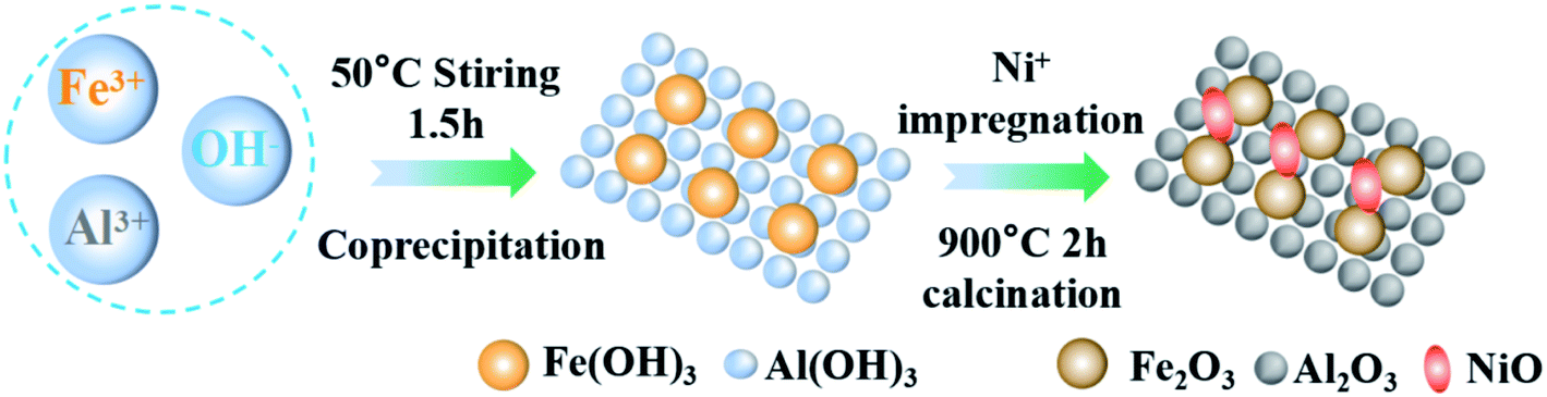 | ||
| Fig. 1 Preparation process of OCs. | ||
Secondly, OCs modified with nickel(II) nitrate hexahydrate (Ni(NO3)2·6H2O), (Sinopharm Chemical Reagent Co., Ltd) were prepared by the impregnation synthesis method. The solution concentration for the impregnation was set as 0, 2.5%, and 5% respectively. The weighed Fe2O3/Al2O3 OCs made from the first step were added to the solution separately. Then placed on a magnetic stirrer for 6 h with agitating intensely. After repeating the steps in the first phase, the NiO–Fe2O3/Al2O3 OCs were obtained. The Fe-based OCs used in this study were smashed by porcelain mortar and sieved by sample points screen to particles within the scope of 0.15 and 0.25 mm.
2.2 Characterization of OCs
The crystalline structure of the OCs was analyzed by using a Rigaku Corporation smartlab X-ray diffraction (XRD) over a 2θ range of 10° to 90°. The metal distribution and surface morphology of the OCs were analyzed at 200 KV by using a Tecnai G2F 20 field emission high-resolution transmission electron microscope (TEM). The micro surface structure of the OCs was analyzed by using a quanta 250 scanning electron microscope (SEM). In a hydrogen atmosphere of 10%, the reducibility of OCs determined by using a hydrogen temperature-programmed (H2-TPR) 20EGA from HIDEN, USA. The temperature and heating rate used for the measurement was 900 °C and 10°C min−1, respectively.2.3 Experimental procedures
The CLSR test system is shown in Fig. 2. The system consists of a feed part, gasification device, hydrogen production reactor, condensation system, and gas analysis part. Before the start of the reaction, 2 g of OCs were placed in the tube in the middle of the fixed bed reactor. When heated, N2 gas was filled as the reaction carrier gas so that the reaction could be carried out under anaerobic conditions.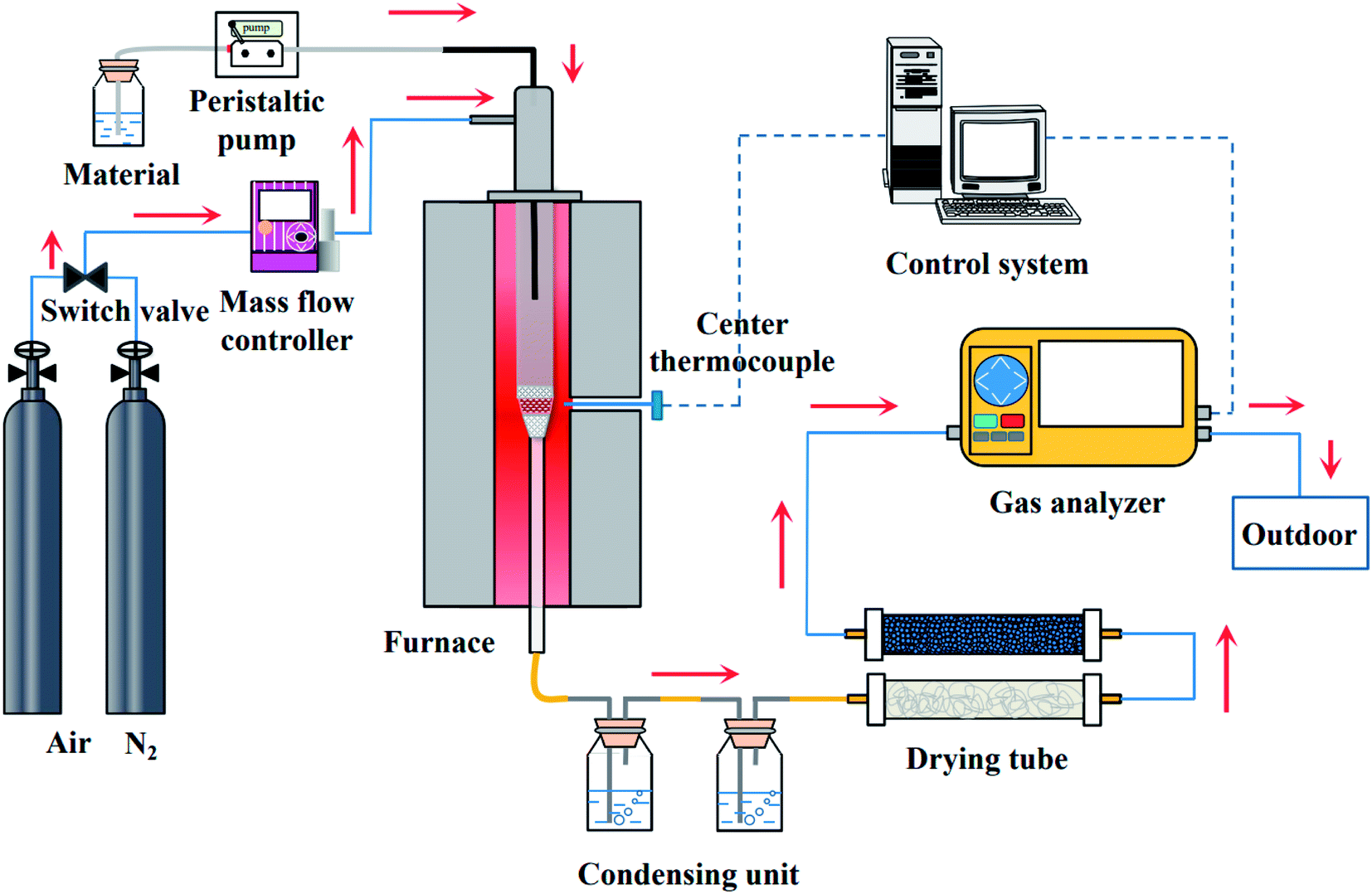 | ||
| Fig. 2 CLSR to hydrogen production system. | ||
At the beginning of the reaction, the aqueous solution of glycerol was pumped into the fixed bed reaction device through a peristaltic pump (BT100-2J, Baoding Longer Pump Co., Ltd). The flow rate of glycerol solution is 0.5 mL min−1. The main component of crude glycerol is propanetriol. We used glycerol for the test to avoid the interference of impurities. It was obtained from Sinopharm Chemical Reagent Co., Ltd The gas flow rate of the N2 remained 300 mL min−1 to ensure the consistency and reliability of the experiment. The time of one cycle is 40 min. The oxidation process and the reduction process are 20 min respectively. After the reaction, N2 is introduced for 20 min to ensure the experiment safely. The reacted gas products were condensed by a condensation device. Meanwhile, the device collected the unreacted glycerol solution and the side products. Non-condensable gas was treated with water absorbent cotton and discolored silicone first. And then passed into the portable infrared flue gas analysis device (Gasboard-3100, Wuhan Cube Optoelectronics Co., Ltd) for real-time detection of the contents of the gases, such as H2, CO, CO2, and CH4, were detected. After the reaction, it was cooled to room temperature in an N2 atmosphere, and the OCs were removed for subsequent characterization.
2.4 Establishment of the orthogonal model
Regression orthogonal test is a method of regression design and analysis by unifying the advantages of orthogonal test design, regression data processing, and regression accuracy.28 In regression orthogonality, experimental sites can be selected appropriately within the range of factors using fewer tests.29,30 A highly accurate and statistically sound regression equation is established and the problem of test optimization can be solved. In this study, a three-factor three-level orthogonal experiment was conducted. A quadratic regression orthogonal model was used and an optimization experimental study was carried out. Three factors affecting H2 production are optimized, namely T, S/C and M. First, the factor level and process parameters in the process of CLSR to hydrogen production are set. The table corresponding to the level of test factors is shown in Table 1S,† and the orthogonal experimental protocol L9(34) is shown in Table 2S.†2.5 Data analysis
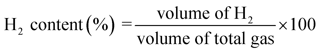
The main products of the CLSR process are H2, CO, and CH4. The H2 content is represented by formula (2.1). In actual operation, part of the CO in the generated gas can be converted into CO2 through a water gas shift (WGS) process31 to increase the H2 yield and H2 concentration. In addition, H2 selectivity is represented by formula (2.2), and CO selectivity is expressed by formula (2.3).
 | (2.1) |
 | (2.2) |
 | (2.3) |
An orthogonal test is a design method for studying multiple factors and multiple levels. It is based on orthogonality to select some representative points from the full-scale test.29 The extreme difference analysis is a kind of analysis method in orthogonal test, which is the difference between the maximum and minimum sign values among the sign values of the overall units, representing the maximum range of sign value variation. The strength of the factors or the specific level between the factors and the dispersion of the data is analyzed by the extreme difference.
Where Ri can be expressed as:
| Ri = Xmax − Xmin | (2.4) |
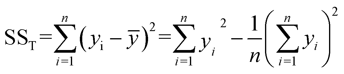
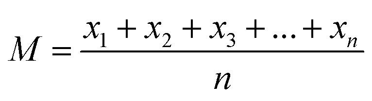
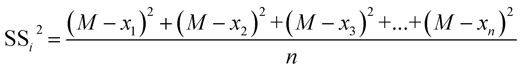
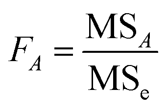
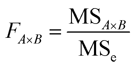
Analysis of variance (ANOVA) is used to test the significance of the difference between the means of two and more samples. It is the average of the squared values of the difference between each sample value and the mean of the whole sample values. It is important for exploring the interaction between the three variables and studying the variance. In particular, the sum of squared total deviations is expressed as SST (eqn (2.5)), which reflects the total variance of the experimental results. The larger the sum of squared total deviations, the greater the variation among experimental results. Variation in the level of factors and experimental error are the causes of the differences between experimental results.
 | (2.5) |
The sum of squares of deviations from the mean of each group of variables from the total mean is expressed in eqn (2.6) and (2.7).
 | (2.6) |
 | (2.7) |
 | (2.8) |
 | (2.9) |
3. Results and discussion
3.1 OCs characterization
The crystal structures of three fresh Fe-based OCs were detected by using X-ray diffraction (XRD) methods. Then the JCPDS database was used to identify the typical peaks of Al2O3, Fe2O3, NiAl2O4, NiFe2O4, AlFeO3, and Al3Fe5O12. The peaks at 2θ = 35.69°,37.31°,53.80°,57.36°, and 62.92° can match the characteristic peaks of the NiFe2O4, overlapping between (114) plane of Al2O3 and (222) plane of NiFe2O4 and overlapping between (116) plane of Fe2O3 and (422) plane of NiFe2O4, respectively.The three OCs were mainly composed of Fe2O3 and Al2O3. Diffraction peaks of Fe2O3 and Al2O3 are seen in Fig. 3. Besides, NiFe2O4, NiAl2O4, and AlFeO3 are observed in the two XRD modes consisting of Ni–Al–Fe. These were due to the reaction in Ni–Al–Fe at a high calcination temperature to form a Fe–Ni and Al–Ni solid solution, respectively. From the position of the diffraction peak, a sample is a cubic form of nickel oxide (NiO).32 The addition of nickel is capable to form a NiFe2O4, NiAl2O4 (ref. 33–35) material with a spinel structure. The previous studies have confirmed that these two structures are more conducive to the CLSR to hydrogen production reaction.13 Two solid solute substances AlFeO3 and Al3Fe5O12 with spinel structures were generated during the calcination of Al2O3 and Fe2O3. The corresponding JCPDS cards are 30-0024 and 49-1657, respectively.36,37
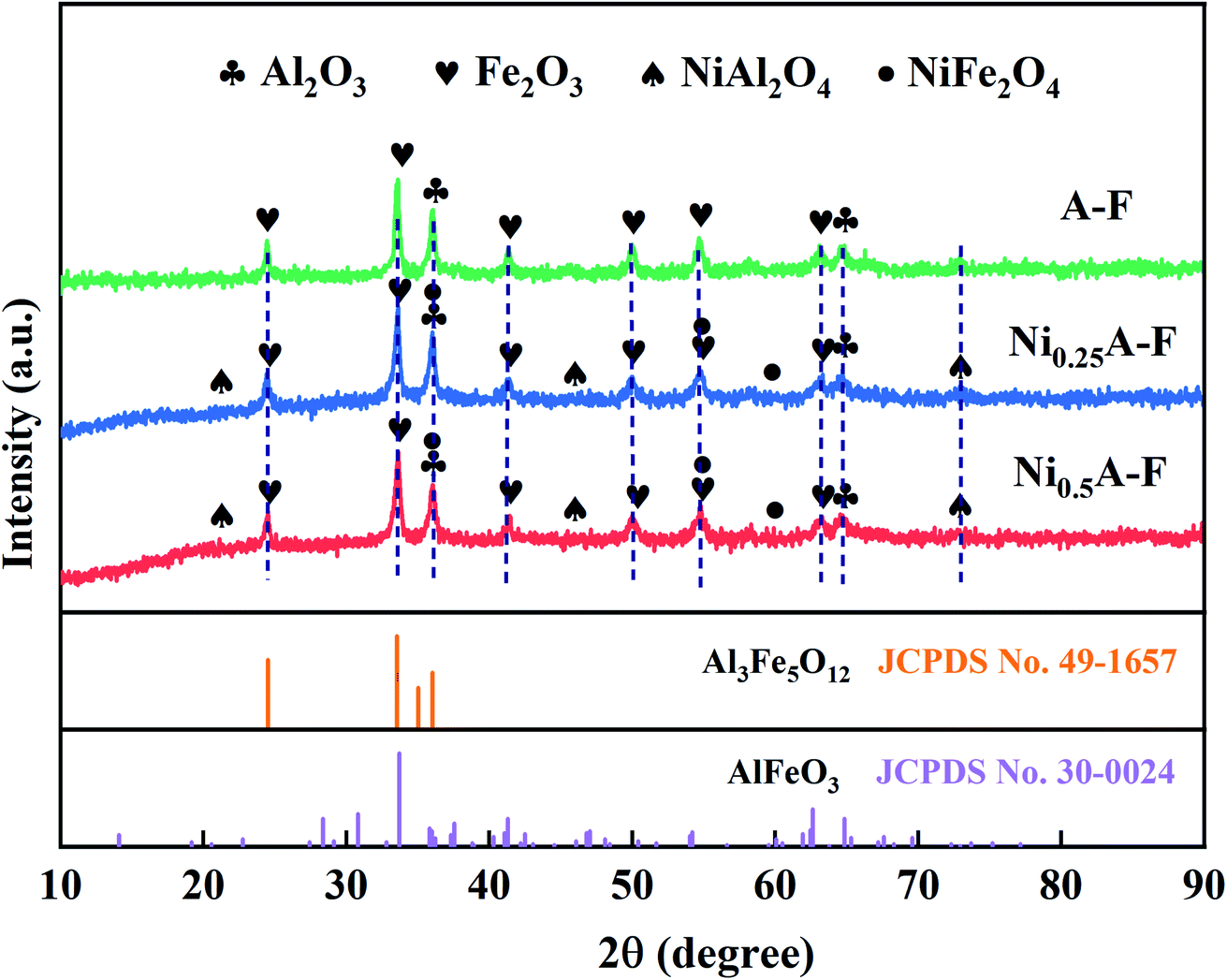 | ||
| Fig. 3 XRD patterns of the samples with different loaded Ni content. | ||
The SEM results of fresh Fe–Al OCs are shown in Fig. 1S† which was prepared by the coprecipitation method. The SEM results do not explicitly reveal the nanoscale features of the condensed metallic phases. The morphology of the sample can be small circular particles lying on large-sized square flat strata.
The distribution of various elements is shown in Fig. 2S.† It can be seen that the active metals are evenly distributed on the OCs surface. A high positive correlation occurred between OCs activity and the dispersion of the surfactant site. The higher dispersion of the active site the higher OCs activity.20 And it effectively suppresses the catalyst inactivation caused by carbon deposition and extends the service life. It is shown in Fig. 2S† that the EDS results of the samples Fe–Al OCs. The proportion of Fe2O3 and Al2O3 is basically following the designed ratio. According to previous studies, the Fe-based the OCs show relatively superior performance when the Fe2O3 content is 60%.32,38
Fig. 4 is XPS spectra of three unreacted OCs detected to characterize surface chemical status. Fig. 4(a) shows the full spectrum of the various elements. The spectra of C 1s (correction spectrum), O 1s, Ni 2p, Al 2p, and Fe 2p are detected on the surface of the particles in the range of binding energy of 0–1400 eV, indicating that Fe, Ni, O, and Al elements exist on the surface of the OCs particle. In Fig. 4(b), the XPS spectrum of metallic Fe appears in the form of bimodal peaks, accompanied by satellite peaks. The surface Fe element of fresh OCs have two Fe3+ peaks located at the binding energy of about 713 eV and 726 eV on the Fe 2p3/2 orbit and a satellite peak is located at 719 eV.
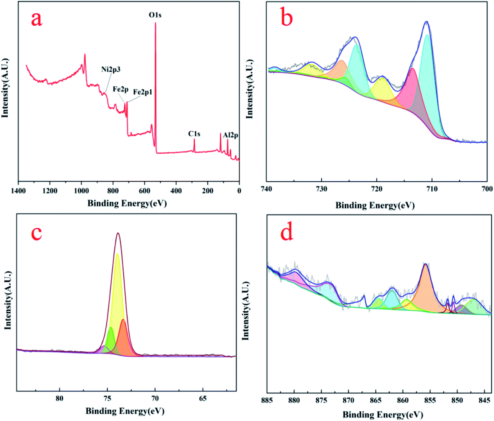 | ||
| Fig. 4 5% OCs XPS patterns of (a) survey (b) Fe element (c) Al element (d) Ni element. | ||
The Fe2+ are found at 711 eV and 723 eV, respectively, and there is also a satellite peak at 733 eV. Compared to the standard oxides (FeO/Fe2O3), the binding energy of Fe2+/Fe3+ of the OCs shows a certain deviation due to the influence of Ni atoms on Fe atoms.18 Fig. 4(c) shows the XPS map of the Al elements, where the peaks of Al are smoother and fitted with four peaks. The highest peak occurs at the position of 74 eV, which represents the Al3+. As shown in Fig. 4(d), three main peaks occurred in Ni 2p3/2 spectra at around 857 eV, 870 eV, and 847.5 eV, reckoned as Ni2+ and shake-up satellite related to Ni2+. It was concluded that the Fe phase highly interacted with the Al2O3 supporting matrix by forming Fe aluminates in NiO–Fe2O3/Al2O3 from these binding energies of the Fe 2p and Al 2p. These XPS results agree well with the XRD results shown in Fig. 3.
The TEM images of three different Ni-loaded fresh OCs are shown in Fig. 5. From a TEM perspective, the unambiguous morphology and crystal symmetry provide a suitable framework that would be beneficial for our next studies. A representational particle is magnified and inserted as a picture in the lower right corner of Fig. 5(a) (scale bar represents 2 nm). As can be seen from Fig. 5(a), the Fe–Al OCs composite is well dispersed. The lattice fringes of the particle different, and the lattice spacing on the left side is 0.143 nm on the right side and 0.258 nm in the picture are corresponding to AlFeO3 [3 0 3] and FeAl2O4 [3 1 1] respectively. And the other size is 0.2770 nm corresponds to Fe2O3 [1 0 4]. The Fast Fourier Transform (FFT) was performed to handle the box-selected parts in the picture.39 The processing picture is shown in the upper right corner in Fig. 5(a). The lattice stripes in the processed pictures are very clear and easy to measure.
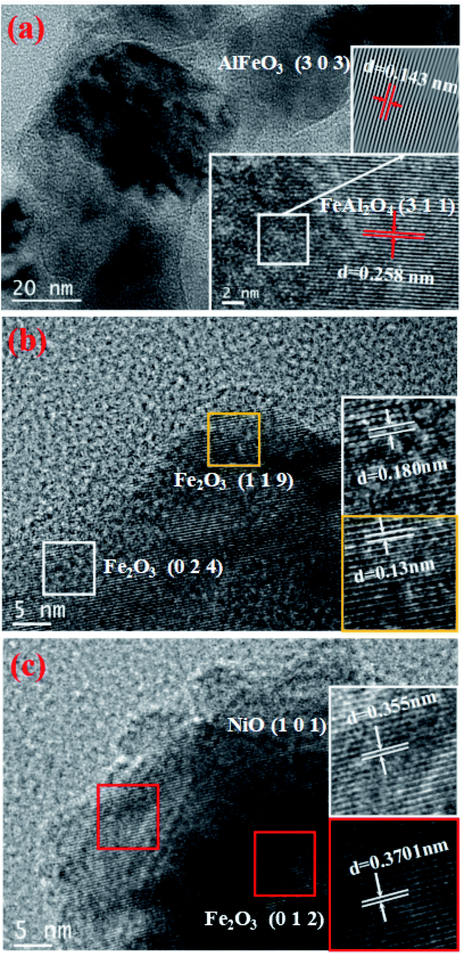 | ||
| Fig. 5 TEM patterns of (a) Fe–Al (b) 2.5% Ni loaded (c) 5% Ni loaded. | ||
Fig. 5(b) shows that the measured lattice spacing d1 = 0.18 nm and d2 = 0.13 nm respectively corresponding to Fe2O3 [0 2 4] and Fe2O3 [1 1 9]. As can be seen from Fig. 5(c), the measured lattice spacing d3 = 0.355 nm d4 = 0.3701 nm respectively correspond to NiO [1 0 1] and Fe2O3 [0 1 2]. These TEM results agree well with the XRD results shown in Fig. 3. From the TEM images, the Fe, Ni, and Al2O3 crystalline phases coexist in the studied NiO–Fe2O3/Al2O3 OCs, which indicates that the Fe and Ni species existing on the prepared NiO–Fe2O3/Al2O3 catalysts can be effectively reduced to low valence metallic Fe and Ni species by glycerol.
The results of H2-TPR of three fresh OCs are shown in Fig. 3S(a).† The peak at around 400 °C is due to a partial reduction of Fe3+ → Fe2+ in the oxide, or Fe2O3 → Fe3O4. The curves corresponding to 2.5% and 5% in Fig. 3S(b)† are Fe-based oxygen loaded with different contents of Ni, with the characteristic peak of hydrogen consumption around 550 °C attributed to Fe3O4 → FeO. Compared with the Fe-based OCs loaded without Ni, the addition of Ni promoter reduced the reduction temperature (the positions of the two hydrogen consumption peaks after 450 °C shift from 630, 850 to 550, 830 °C), indicating that the addition of Ni facilitates the reduction of metal oxides on the catalyst and makes the reaction easier.40
After five cycles of OCs Ni loaded of 2.5% and 5% under different reaction conditions are as shown in Fig. 3S(c) and (d),† respectively. Three reduction peaks were located at 360, 455, and 690 °C. In Fig. 3S(c),† the peak at 360 °C is very weak and corresponds to the reduction of iron oxide from high price to low valence. The peak is very strong at 690 °C attributed to the formation of metallic iron. Accordingly, the peaks were shifted to higher temperatures at the condition 800 °C and S/C of 1.5. There is a distinct peak at 510 °C and another peak at 700 °C. The initial reduction peak due to significant oxygen loss was at 300 °C but the CM was at 650 °C. There was a significant negative offset of 350 °C as compared to the CM. There is a markedly negative shift of 218 °C, as compared to the CM. Therefore, in order to maximize the degree of hypoxia without damaging its spinel structure, the H2 reduction temperature should be chosen at 600 °C.41
3.2 Experimental results and parameter optimization
During the CLSR experiments, T, S/C, and M play an important role. Inappropriate T can produce OCs sintering and poor agglomeration cycle performance.42 Too high S/C can lead to difficulties in feeding and are not conducive to adequate fuel reaction.33 Different metal M can also affect the experimental results.7 Therefore, in this study, the effects of three factors, T (A), S/C (B), and M (C), on hydrogen selectivity and hydrogen content were chosen. Table 1 shows the experimental results after testing and calculation. From the experimental results, it can be seen that the hydrogen selectivity in the glycerol steam reforming hydrogen production experiments ranged from 74.67% to 83.01%, and the H2 content ranged from 62.73% to 78.41%. Sequential analysis of the effect of each factor on hydrogen selectivity and hydrogen content was carried out through extreme difference and variance analysis. A quadratic orthogonal regression model was used for regression analysis of the obtained results and quadratic regression equations were developed to analyze the significance of the effects of the factors.| Test number | Column number | Experimental result | |||||
|---|---|---|---|---|---|---|---|
| 1(A) | 2(B) | 3(C) | 4 | H2 selectivity | H2 content | ||
| 1 | 1 | 1 | 1 | 1 | 85.33 | 78.41 | |
| 2 | 1 | 2 | 3 | 2 | 79.24 | 59.88 | |
| 3 | 1 | 3 | 2 | 3 | 83.01 | 74.51 | |
| 4 | 2 | 1 | 2 | 3 | 78.28 | 64.96 | |
| 5 | 2 | 2 | 1 | 1 | 82.30 | 66.62 | |
| 6 | 2 | 3 | 3 | 2 | 77.02 | 62.73 | |
| 7 | 3 | 1 | 3 | 2 | 78.27 | 56.35 | |
| 8 | 3 | 2 | 2 | 3 | 74.67 | 63.06 | |
| 9 | 3 | 3 | 1 | 1 | 79.32 | 67.17 | |
Table 2 shows the significant effects of each factor at different levels for different factors. ANOVA and significance tests were used to obtain the most influential factor. The major and minor factors affecting the hydrogen selectivity were A > C > B. That is the T had the greatest effect on the hydrogen content. The major and minor factors affecting the hydrogen content were C > A > B. That is the M had the greatest effect on the hydrogen content. The least effect was produced by S/C.
| Analytic target | Analyze parameters | A (T) | B (S/C) | C (M) | Best collocation | Effect of priorities |
|---|---|---|---|---|---|---|
| H2 selectivity | Ri | 5.11 | 1.89 | 4.14 | A1B1C1 | A > C > B |
| SSi | 40.312 | 5.391 | 30.769 | |||
| Significance test | * | — | * | |||
![[thin space (1/6-em)]](https://www.rsc.org/images/entities/char_2009.gif) |
||||||
| H2 content | Ri | 8.74 | 4.95 | 11.08 | A1B3C1 | C > A > B |
| SSi | 120.971 | 38.374 | 194.729 | |||
| Significance test | * | — | * | |||
Using hydrogen selectivity as an indicator, the regression equation is as follows:
 | (3.2.1) |
The significance of the established hydrogen selectivity model was 0.009 < 0.05 therefore the selected model is reliable.
Using the hydrogen content as an indicator, the regression equation is as follows:
 | (3.2.2) |
The effects of T2 and M2 on yHL were highly significant and the other terms did not have significant effects on y. The model developed for hydrogen content was significant 0.005 < 0.05 therefore the chosen model is reliable.
3.3 OCs performance and cycle stability analysis
Fig. 6 is a summary graph of the hydrogen content for three different temperatures and different Ni loaded of the OCs cycled 1–5 times at S/C of 1.0. From the graph, it can be seen that the hydrogen content shows a rising and then gradually leveling off. The red histogram is the unloaded OCs. Its hydrogen content fluctuates more, from 74% to 59% with a 15% fluctuation. The blue and yellow bar graphs are the OCs with Ni loading of 2.5% and 5%, respectively. The OCs after Ni loading change from 62% to 58% and 55% to 48%, respectively. They fluctuate by 4% and 7%, respectively. The results show that the addition of Ni can improve the stability of the OCs. This may be due to the good bond-breaking effect of Ni, which is able to break the bond when the glycerol vapor is involved in the reaction. Therefore, it makes the reaction proceed more smoothly and avoids the occurrence of carbon deposition.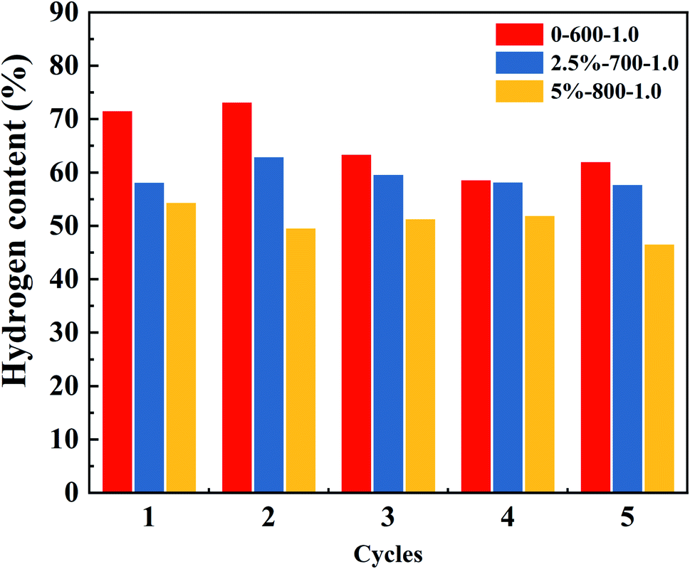 | ||
| Fig. 6 Summary of the hydrogen content in 5 cycles at 0%-600-1.0, 2.5%-700-1.0, 5%-800-1.0. | ||
Fig. 5S† shows the percentage of the components in the 5 cycles under the first operating condition. In each cycle, the hydrogen content ranks first with a steady-state range of 73–62%. The H2 content decreased sharply at the beginning of the reaction as can be seen from the hydrogen content map in Fig. 5S.† This is because the oxygen vacancy on the OCs can then react completely with the incoming glycerol solution vapor to maximize the hydrogen content at an instant at the beginning of the reaction.43 As the reaction proceeds, the oxygen vacancy contacted by the glycerol solution vapor gradually decreases, and the hydrogen content decreases rapidly because the oxygen vacancy is occupied by the deposited carbon. The hydrogen content was eventually stabilized within a certain range. This process occurs within one minute after the reaction begins. The overall content of hydrogen is higher than the other gas components, and the content of CO, CO2, and CH4 is lower.
Fig. 7 shows the 1st, 3rd, and 5th cycle content of hydrogen and methane under different working conditions. It can be clearly seen that the gas content varies greatly within 5 min. The fluctuation of hydrogen content tends to decrease and then increase with the increase of Ni loading. The Ni loading at 2.5% possesses better cycling stability, which is the same as the above conclusion. The changing characteristics of the pore structure and composition distribution of OCs particles in the redox cycle may occur mainly in the first two cycles. As the reaction proceeds, the activity of the OCs gradually decreased. This is due to the fact that the oxygen vacancies are partially covered by carbon accumulation during the reaction process, which prevents the reaction of the active component with the fuel and thus leads to the deactivation of the OCs.
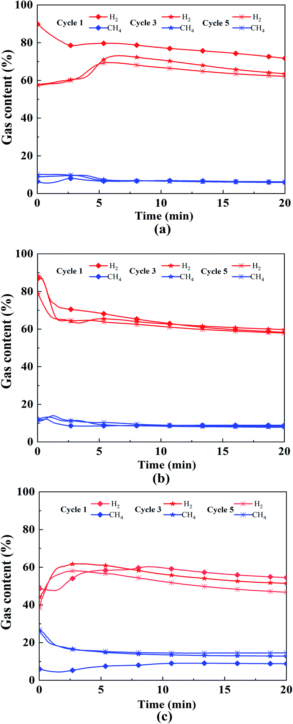 | ||
| Fig. 7 1st, 3rd and 5th cycle content of hydrogen and methane: (a) 0% 600 °C 1.0, (b) 2.5% 700 °C 1.0, (c) 5% 800 °C 1.0. | ||
3.4 Understanding of the CLSR mechanism
Eqn (3.1)–(3.5) represent the mechanism of CLSR. The fuel vapor first reduces the oxygen carrier by water vapor shift (WGS) and water vapor reforming reactions to produce CO2, H2O, and metal monomers44 (eqn (3.1) and (3.2)). The metal monomers attached to the surface of the carrier and the water vapor then react to partially oxidize the metal monomers while producing H2 (eqn (3.3)). Finally, the OCs are burned in an air atmosphere to remove the carbon deposits produced by the reaction while allowing the oxygen carrier to be completely oxidized.45 The OCs are restored to the initial state before the reaction in the ideal state providing the prerequisite for the next cycle to proceed.| 2CxHyOz + (4x + y − 2z)MeO → 2xCO2 + yH2O + (4x + y − 2z)Me | (3.1) |
| 2CxHyOz + 2(x − z)MeO → 2xCO + yH2 + 2(x − z)Me | (3.2) |
| Me + (1 − ζ)H2O → MeO1−ζ + (1 − ζ)H2 | (3.3) |
| 2Me + O2 → 2MeO | (3.4) |
| 2MeO(1−ζ) + ζO2 → 2MeO | (3.5) |
Fig. 8 and 6S† show the glycerol steam reforming to the hydrogen pathway. The first stage is glycerol dehydration. 1 mol of glycerol is removed from 2 mol of H2O and the product is acrolein.46 Acrolein is decomposed by heating to produce H2, CH4, C2H4, C3H6, and other gases. The final stage produced the CO. On the other hand, the breakage of the C–C bond leads to the removal of 1 mol of water from glycerol through the broken bond producing CH2O, CH4, and CO.47,48 CO and H2O undergo water vapor conversion, while co reacts with 3 mol H2. The side reaction is the CO methanation reaction to produce CH4. The CO2 produced during the water vapor conversion process reacts with H2 to form H2O and CH4. The heat released during this process can be used to compensate for the heat lost in the reactor to achieve energy savings.
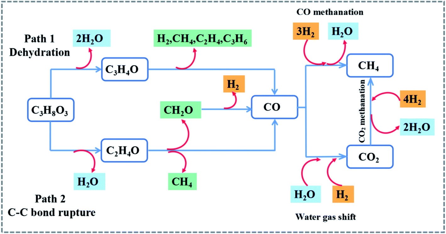 | ||
| Fig. 8 Glycerol steam reforming to hydrogen pathway. | ||
Ni particles were uniformly distributed on the OCs surface, which was combined with SEM analysis. As shown in Fig. 9, the activity of OCs increased mainly due to the incorporation of Ni. The fundamentals of Fe-based OCs loaded with metallic Ni are currently being investigated in depth. The modification of Fe-based OCs by the addition of Ni is due to the ability of Fe and Ni to form two substances with spinel structure: NiFe2O4 and NiAl2O4, which play a positive role in the CLSR process of hydrogen production. Some researchers consider the oxidation and reduction of NiFe2O4 as a stepwise process due to the formation of complex spatial structures with multivalent states of metals.16 The lattice oxygen migrating to the surface is hydroxylated with radicals (H) to form H2O. The lattice oxygen is continuously consumed by the fuel as the reaction proceeds until the reduction product Fe (Ni) is produced.49 In the water vapor–air oxidation stage, the released lattice oxygen is restored as the oxygen concentration gradient drives the lattice oxygen to continuously migrate from the surface to fill the oxygen vacancies as a whole.16
 | ||
| Fig. 9 Schematic diagram of the NiO assisted Fe-based CLSR process to hydrogen production. | ||
4. Conclusion
In this study, a series of experiments on CLSR to hydrogen production was performed in a fixed-bed reactor using Ni-modified Fe-based OCs. The Fe-based OCs loaded by 2.5% and 5% Ni were compared with unloaded OCs. The optimal conditions for hydrogen content and hydrogen selectivity were determined separately. The optimal combination of hydrogen content was A1B3C1 (T = 600 °C S/C = 2.0 M = 0) and the optimal combination of hydrogen selectivity was A1B1C1 (T = 600 °C S/C = 1.0 M = 0). The Fe-based OCs modified with Ni had good cycling stability. Stable nanostructures between the particles were observed by field emission scanning electron microscopy (SEM). ANOVA and significance tests were used to obtain the most influential factor. The hydrogen content in the order of C > A > B was found. The major and minor factors affecting the hydrogen selectivity were A > C > B. A quadratic regression orthogonal model was established T and M two significant influencing factors were identified. The hydrogen content fluctuated within 4% was obtained under T = 700 °C, S/C = 1.0 mol mol−1, and M = 2.5%. Therefore, NiO–Fe2O3/Al2O3 was a promising OCs for hydrogen production from glycerol.Conflicts of interest
There are no conflicts to declare.Nomenclature
| T | Temperature (°C); |
| S/C | Water/carbon ratio (mol mol−1); |
| M | Load capacity; |
| Ri | Extreme difference; |
| Xmax | Maximum and minimum values of k; |
| Xmin | Minimum values of k; |
| SST | The sum of squared total deviations; |
| SSi | The variance value; |
| FA | F-value of A; |
| FA×B | F-value of A, B interaction; |
| MSA | The mean square of the A factor; |
| MSA×B | The mean square of A, B interaction |
Acknowledgements
Hetong Li: investigation; data curation; writing-original draft; writing-review & editing. Yuchun Zhang: supervision; conceptualization; funding acquisition; project administration. Peng Fu: conceptualization; methodology; funding acquisition; project administration. Ranran Wei: visualization. Zhiyu Li: data curation; supervision. Lei Dai: software; visualization. Andong Zhang: data curation; validation. This work was supported by the Natural Science Foundation of China [grant numbers 51976112, 51676116, 52130610]; the National Key Research and Development Project of China [grant number 2019YFD1100602].References
- B. Dou, L. Zhao and H. Zhang, et al., Renewable hydrogen production from chemical looping steam reforming of biodiesel byproduct glycerol by mesoporous oxygen carriers, Chem. Eng. J., 2021, 416, 127612 CrossRef CAS.
- B. Jiang, B. Dou and Y. Song, et al., Hydrogen production from chemical looping steam reforming of glycerol by Ni-based oxygen carrier in a fixed-bed reactor, Chem. Eng. J., 2015, 280, 459–467 CrossRef CAS.
- S. T. S. Veras, P. Rojas and L. Florencio, et al., Production of 1,3-propanediol from pure and crude glycerol using a UASB reactor with attached biomass in silicone support, Bioresour. Technol., 2019, 279, 140–148 CrossRef CAS PubMed.
- L. R. Kumar, S. K. Yellapu and R. D. Tyagi, et al., A review on variation in crude glycerol composition, bio-valorization of crude and purified glycerol as carbon source for lipid production, Bioresour. Technol., 2019, 293, 122155 CrossRef CAS PubMed.
- Y. Sun, Y. Zheng and X. Wang, et al., Fermentation performance and mechanism of a novel microbial consortium DUT08 for 1,3-propandiol production from biodiesel-derived crude glycerol under non-strictly anaerobic conditions, Process Biochem., 2019, 83, 27–34 CrossRef CAS.
- D. Liu, B. Dou and H. Zhang, et al., Comparison of gelatinous and calcined magnesia supported Ni or/and Co-based catalysts for aqueous phase reforming of glycerol, Renewable Energy, 2022, 186, 656–666 CrossRef CAS.
- K. Wu, B. Dou and H. Zhang, et al., Aqueous phase reforming of biodiesel byproduct glycerol over mesoporous Ni–Cu/CeO2 for renewable hydrogen production, Fuel, 2022, 308, 122014 CrossRef CAS.
- M. Zhu, Y. Song and S. Chen, et al., Chemical looping dry reforming of methane with hydrogen generation on Fe2O3/Al2O3 oxygen carrier, Chem. Eng. J., 2019, 368, 812–823 CrossRef CAS.
- J. Hu, S. Chen and W. Xiang, Sintering and agglomeration of Fe2O3–MgAl2O4 oxygen carriers with different Fe2O3 loadings in chemical looping processes, Fuel, 2020, 265, 116983 CrossRef CAS.
- X. Zhu, Q. Imtiaz and F. Donat, et al., Chemical looping beyond combustion – a perspective, Energy Environ. Sci., 2020, 13(3), 772–804 RSC.
- J. Liu, R. Hu and X. Liu, et al., Modeling of propane dehydrogenation combined with chemical looping combustion of hydrogen in a fixed bed reactor, Chin. J. Chem. Eng., 2022, 47, 165–173 CrossRef.
- B. Dou, H. Zhang and G. Cui, et al., Hydrogen production by sorption-enhanced chemical looping steam reforming of ethanol in an alternating fixed-bed reactor: sorbent to catalyst ratio dependencies, Energy Convers. Manage., 2018, 155, 243–252 CrossRef CAS.
- K. Wang, Q. Yu and H. Xie, et al., Properties of Cu-based Oxygen Carrier Used for Chemical Looping Oxygen Production, J. Inorg. Mater., 2013, 28(10), 1115–1120 CrossRef CAS.
- K. Wang, Q. Yu and Q. Qin, et al., Kinetics Analysis of Cu–Zr Oxygen Carrier for Chemical Looping Oxygen Production, J. Inorg. Mater., 2014, 29(3), 301–308 CAS.
- G. Tang, J. Gu and G. Wei, et al., Syngas production from cellulose solid waste by enhanced chemical looping gasification using Ca–Fe bimetallic oxygen carrier with porous structure, Fuel, 124106, 2022, 322 Search PubMed.
- N. Yuan, H. Bai and M. An, et al., Modulation of Fe-based oxygen carriers by low concentration doping of Cu in chemical looping process: reactivity and mechanism based on experiments combined with DFT calculations, Powder Technol., 2021, 388, 474–484 CrossRef CAS.
- G.-q. Wei, J. Feng and Y.-L. Hou, et al., Ca-enhanced hematite oxygen carriers for chemical looping reforming of biomass pyrolyzed gas coupled with CO2 splitting, Fuel, 2021, 285, 119125 CrossRef CAS.
- Z. Huang, N. Gao and Y. Lin, et al., Exploring the migration and transformation of lattice oxygen during chemical looping with NiFe2O4 oxygen carrier, Chem. Eng. J., 2022, 429, 132064 CrossRef CAS.
- E. Karimi, H. R. Forutan and M. Saidi, et al., Experimental Study of Chemical-Looping Reforming in a Fixed-Bed Reactor: Performance Investigation of Different Oxygen Carriers on Al2O3 and TiO2 Support, Energy Fuels, 2014, 28(Mar.–Apr.), 2811–2820 CrossRef CAS.
- Z. Ma, R. Xiao and L. Chen, Redox reaction induced morphology and microstructure evolution of iron oxide in chemical looping process, Energy Convers. Manage., 2018, 168, 288–295 CrossRef CAS.
- N. L. Galinsky, A. Shafiefarhood and Y. Chen, et al., Effect of support on redox stability of iron oxide for chemical looping conversion of methane, Appl. Catal., B, 2015, 164, 371–379 CrossRef CAS.
- S. Bhavsar and G. t. Veser, Bimetallic Fe–Ni oxygen carriers for chemical looping combustion, Ind. Eng. Chem. Res., 2013, 52(44), 15342–15352 CrossRef CAS.
- Y. De Vos, M. Jacobs and P. Van Der Voort, et al., Optimization of spray dried attrition-resistant iron based oxygen carriers for chemical looping reforming, Chem. Eng. J., 2017, 309, 824–839 CrossRef CAS.
- Y. Zhao, B. Jin and X. Luo, et al., Thermodynamic evaluation and experimental investigation of CaO-assisted Fe-based chemical looping reforming process for syngas production, Appl. Energy, 2021, 288, 116614 CrossRef CAS.
- J. Hu, S. Chen and X. W. Ni, Co and Cu-promoted iron-based oxygen carriers in methane-fueled chemical looping hydrogen generation process, Fuel Process. Technol., 2021, 221, 106917 CrossRef CAS.
- J. Huang, A. Veksha and T. Foo Jin Jun, et al., Upgrading waste plastic derived pyrolysis gas via chemical looping cracking–gasification using Ni–Fe–Al redox catalysts, Chem. Eng. J., 2022, 438, 135580 CrossRef CAS.
- C. Luo, B. Dou and H. Zhang, et al., Co-production of hydrogen and syngas from chemical looping water splitting coupled with decomposition of glycerol using Fe–Ce–Ni based oxygen carriers, Energy Convers. Manage., 2021, 238, 114166 CrossRef CAS.
- A. D. Kiadehi, M. Taghizadeh and M. J. Azarhoosh, et al., Hydrogen production using ethylene glycol steam reforming in a micro-reformer: experimental analysis, multivariate polynomial regression and genetic programming modeling approaches, J. Taiwan Inst. Chem. Eng., 2020, 112, 20–33 CrossRef CAS.
- Y. Zhang, J. Yuan and L. Guo, Enhanced bio-hydrogen production from cornstalk hydrolysate pretreated by alkaline-enzymolysis with orthogonal design method, Int. J. Hydrogen Energy, 2020, 45(6), 3750–3759 CrossRef CAS.
- S. Ma, H. Wang and Y. Wang, et al., Bio-hydrogen production from cornstalk wastes by orthogonal design method, Renewable Energy, 2011, 36(2), 709–713 CrossRef CAS.
- L.-P. Merkouri, E. Le Saché and L. Pastor-Pérez, et al., Versatile Ni–Ru catalysts for gas phase CO2 conversion: bringing closer dry reforming, reverse water gas shift and methanation to enable end-products flexibility, Fuel, 2022, 315, 123097 CrossRef CAS.
- Z. Ma, S. Zhang and Y. Lu, Phase segregation mechanism of NiFe2O4 oxygen carrier in chemical looping process, Int. J. Energy Res., 2021, 45(2), 3305–3314 CrossRef CAS.
- S. Sun, S. He and C. Wu, Ni promoted Fe–CaO dual functional materials for calcium chemical dual looping, Chem. Eng. J., 2022, 441, 135752 CrossRef CAS.
- X. Sun, L. Zhu and W. Zhao, et al., Ni–Fe bimetallic hexaaluminate for efficient reduction of O2-containing CO2 via chemical looping, Chem. Eng. J., 2022, 441, 136071 CrossRef CAS.
- C. Luo, B. Dou and H. Zhang, et al., Hydrogen and syngas co-production by coupling of chemical looping water splitting and glycerol oxidation reforming using Ce–Ni modified Fe-based oxygen carriers, J. Cleaner Prod., 2022, 335, 130299 CrossRef CAS.
- T. Xu, X. Wang and B. Xiao, et al., Optimisation of syngas production from a novel two-step chemical looping reforming process using Fe-dolomite as oxygen carriers, Fuel Process. Technol., 2022, 228, 107169 CrossRef CAS.
- K. Tippey, A. Nakano and J. Nakano, et al., In situ analysis of the Al-Fe-Mn–Cu oxide oxygen carrier for chemical looping applications, Chem. Eng. J. Adv., 2022, 9, 100203 CrossRef.
- Z. Ma, S. Zhang and R. Xiao, Insights into the relationship between microstructural evolution and deactivation of Al2O3 supported Fe2O3 oxygen carrier in chemical looping combustion, Energy Convers. Manage., 2019, 188, 429–437 CrossRef CAS.
- H. Wang, Y. Fang and Y. Liu, et al., Perovskite LaFeO3 supported bi-metal catalyst for syngas methanation, J. Nat. Gas Chem., 2012, 21(6), 745–752 CrossRef CAS.
- Z.-q. Liu, J. Zheng and Y. Wang, et al., Selective reduction of carbon dioxide into amorphous carbon over activated natural magnetite, Int. J. Miner., Metall. Mater., 2021, 28(2), 231–237 CrossRef CAS.
- W. Qian, H. Zhang and Q. Sun, et al., Effects of Zr and Ni promoters on the activation and deactivation of a precipitated iron-based catalyst for Fischer–Tropsch synthesis, React. Kinet., Mech. Catal., 2014, 111(1), 293–304 CrossRef CAS.
- Y. Cao, H. Zhang and X. Liu, et al., A strategy of mid-temperature natural gas based chemical looping reforming for hydrogen production, Int. J. Hydrogen Energy, 2022, 47(24), 12052–12066 CrossRef CAS.
- B. Jiang, L. Li and Z. Bian, et al., Hydrogen generation from chemical looping reforming of glycerol by Ce-doped nickel phyllosilicate nanotube oxygen carriers, Fuel, 2018, 222, 185–192 CrossRef CAS.
- H. Tian, C. Pei and S. Chen, et al., Regulation of Oxygen Activity by Lattice Confinement over NixMg1−xO Catalysts for Renewable Hydrogen Production, Engineering, 2022, 12, 62–69 CrossRef.
- Q. Zhang, L. Li and B. Jiang, et al., Hydrogen by chemical looping reforming of ethanol: the effect of promoters on La2−xMxNiO4−λ (M = Ca, Sr and Ce) oxygen carriers, Chem. Eng. Sci., 2017, 174, 259–267 CrossRef CAS.
- K. Polychronopoulou, A. A. Dabbawala and M. Sajjad, et al., Hydrogen production via steam reforming of glycerol over Ce–La–Cu–O ternary oxide catalyst: an experimental and DFT study, Appl. Surf. Sci., 2022, 586, 152798 CrossRef CAS.
- W. Cheng, Y. Wang and M. Chen, et al., Hydrogen production from aqueous phase reforming of glycerol over attapulgite-supported nickel catalysts: effect of acid/base treatment and Fe additive, Int. J. Hydrogen Energy, 2022, 47(11), 7082–7099 CrossRef CAS.
- N. A. Roslan, S. Z. Abidin and O. U. Osazuwa, et al., H2-rich syngas from glycerol dry reforming over Ni-based catalysts supported on alumina from aluminum dross, Int. J. Hydrogen Energy, 2021, 46(60), 30959–30975 CrossRef CAS.
- H. Zhou, Q. Yi and G. Wei, et al., Reaction performance and lattice oxygen migration of MnFe2O4 oxygen carrier in methane-carbon dioxide reaction system, Int. J. Hydrogen Energy, 2020, 45(55), 30254–30266 CrossRef CAS.
Footnote |
| † Electronic supplementary information (ESI) available. See https://doi.org/10.1039/d2ra04303c |
| This journal is © The Royal Society of Chemistry 2022 |