 Open Access Article
Z-scheme LaCoO3/C3N5 for efficient full-spectrum light-simulated solar photocatalytic hydrogen generation
Rui Wangac,
Kexin Zhanga,
Xin Zhong b and
Fubin Jiang
 *ab
*ab
aCollege of Chemistry, Beijing Normal University, Beijing, 100875, China. E-mail: jfb@bnu.edu.cn; Tel: +86 01058802850
bDepartment of Chemistry, Faculty of Arts and Sciences, Beijing Normal University, Zhuhai, 519087, China
cInstitute of Chemical Engineering and Technology, Xi'an Jiao Tong University, Xi'an, 710049, China
First published on 24th August 2022
Abstract
The development of photocatalysts with high activity and low cost is still a major challenge. Since its synthesis in 2019, C3N5 has become an emerging photocatalytic material and has been widely studied. In this work, we report on the preparation of LaCoO3/C3N5 nanosheets and the use of LaCoO3 instead of precious metals to improve photocatalytic hydrogen production activity. First, LaCoO3 was successfully prepared by the sol–gel method and then a series of high-efficiency Z-type LaCoO3/C3N5 heterojunction photocatalysts were synthesized by the solvothermal method. Various characterization techniques (XRD, FT-IR, SEM, TEM, EDS, XPS, UV-Vis DRS, BET, ESR) confirmed the formation between LaCoO3 nanoparticles and C3N5 nanosheet heterostructures and interface interactions. In the photocatalytic water split test, 50 wt% LaCoO3/C3N5 showed the highest photocatalytic activity of 956.11 μmol h−1 g−1, which was 3.21 and 1.59 times that of LaCoO3 and C3N5, respectively. This work not only designs an inexpensive and efficient LaCoO3/C3N5 photocatalytic system for water splitting or other photocatalytic applications, but also provides ideas for constructing new material photocatalytic systems.
1. Introduction
With the rapid development of industry and the increasing industrialization of the economy and society, human demand for energy is increasing. Photocatalysis is an effective method for converting solar energy into chemical energy. To date, the most extensive research has involved solar photovoltaic cells and photocatalytic hydrolysis to produce hydrogen and carbon dioxide. Among them, photocatalytic water hydrogen production is an effective green and sustainable method with the potential to solve our current energy dilemma.1–3Graphite carbon nitride is a typical metal-free organic polymer semiconductor photocatalyst.4–7 The reason why it is widely used is that it has the advantages of a suitable band gap, high chemical stability during the visible light response and easy preparation.8–11 Karthik Shankar's research group12 changed the synthesis method to synthesize a new type of carbon nitride material, C3N5 is used for methylene blue degradation experiments. Compared with the previous C3N4, C3N5 has many advantages, when used as the electron transport layer (ETL) of halide perovskite solar cells, the performance of C3N5 is better than that of g-C3N4, especially for generating open-circuit light voltages up to 1.3 V. The narrow band gap and two-dimensional structure of C3N5 make it an interesting air and high-temperature resistant semiconductor in optoelectronic applications, while its electronic-rich properties and on-chip cavity make it attractive for environmental applications. Siyun Qi et al.13 demonstrated from first-principles calculations that C3N5 multilayers can serve as promising candidates to product hydrogen via photocatalytic water splitting reaction. Dazhong Sun et al.14 demonstrated the most potential for overall water splitting to be the easiest to synthesize experimentally via formation energy calculation of 18 structures. At present, the research on C3N5 photocatalytic water splitting is still in the stage of computational chemistry. In this article, our systematic experiments verify the photocatalytic action and mechanism of C3N5 and its complexes.
Recently perovskite-type semiconductor materials have aroused great interest among researchers.15–22 Because of their adjustable band gap, strong photocorrosion resistance and sufficient oxygen vacancies, they have become very promising photocatalysts.23–28 With these characteristics, they are excellent materials for solar cells and photocatalytic reactions, and they have attracted great attention from researchers.
According to previous experimental reports, we believe that C3N5 is a potential photocatalytic hydrogen production catalyst. We used it to degrade water under full-spectrum light irradiation. A series of photocatalysts were prepared by combining perovskite and C3N5. First, C3N5 was prepared by the method reported by the Karthik Shankar group, and the perovskite photocatalytic material LaCoO3 was prepared by the sol–gel method. Then, the perovskite was loaded on C3N5 by ultrasonic dispersion, overnight stirring, and the solvothermal method. LaCoO3/C3N5 photocatalysts with different mass percentages of 10 wt%, 30 wt%, 50 wt%, 70 wt%, and 90 wt% were added. After that, the photocatalytic performance of C3N5 under full-spectrum light irradiation and the optimal doping ratio of the catalyst after doping were tested by photocatalysis. In addition, we carried out XRD, SEM, TEM, EDS, XPS, PL, FT-IR, UV-Vis DRS, EPR.
2. Experimental section
2.1. Materials
Lanthanum nitrate hexahydrate (purity > 99.99%), cobalt nitrate hexahydrate (purity > 99.99%), citric acid (purity > 99%), and urea (purity > 99%) were used. All other reagents used in this study were analytically pure and used without further purification. Deionized water was used for all of the experiments.2.2. Catalyst preparation
(1) Synthesis of melem (2,5,8-triamino-s-heptazine). A certain amount of melamine was heated in a covered alumina crucible at 425 °C overnight. A light yellow powder was obtained, crushed and suspended in deionized water. The suspension was refluxed for several hours to remove unreacted melamine and other impurities. The resulting white product was collected by centrifugation and dried at room temperature.
(2) Synthesis of 2,5,8-trihydrazino-s-heptazine. Take 1.6 g (7.5 mmol) of the product melem from the previous step in 15 mL (0.25 mol) of 55% hydrazine hydrate aqueous solution, and seal it in a 25 mL Teflon lined autoclave. The autoclave was heated in an oven at 140 °C for 24 hours and then cooled, and the obtained light yellow solution suspension was transferred to a 100 mL beaker. Add 10% HCl to keep the pH between 1–2. The solution was filtered to remove unreacted solid residues containing residues. The filtrate was precipitated by adding 10% NaOH solution and maintaining the pH between 7.5–8.5. The resulting solid was dissolved in HCl again, filtered and reprecipitated in NaOH, repeated three times. Finally, the obtained solid was washed several times with deionized water and ethanol and dried under vacuum.
(3) Synthesis of C3N5 polymer. The C3N5 polymer was synthesized by heating 2,5,8-trihydrazino-s-heptazine (2,5,8-trihydrazino-sheptazine) at a temperature of 450 °C and a heating rate of 2 °C at 450 °C for 2 hours. The obtained orange powder can be used in subsequent experiments without further manipulation.
![[thin space (1/6-em)]](https://www.rsc.org/images/entities/char_2009.gif) :
:![[thin space (1/6-em)]](https://www.rsc.org/images/entities/char_2009.gif) 1
1![[thin space (1/6-em)]](https://www.rsc.org/images/entities/char_2009.gif) :
:![[thin space (1/6-em)]](https://www.rsc.org/images/entities/char_2009.gif) 2. The above three reactants were weighed and dissolved in 10 mL of secondary water to obtain a purple-red solution. During the preparation process, other ions should be preventing from mixing into the solution, and the instrument should be rinsed with water twice before use.
2. The above three reactants were weighed and dissolved in 10 mL of secondary water to obtain a purple-red solution. During the preparation process, other ions should be preventing from mixing into the solution, and the instrument should be rinsed with water twice before use.(2) Transfer the solution from the previous step to a round-bottom flask, heat it in a water bath at 80 °C, and stir it magnetically until the solution becomes a purple sol.
(3) Pour the sol obtained in the previous step into a clean ceramic crucible and dry it at 120 °C in a blast drying box to obtain a swollen purple dry gel, which is ground for later use.
(4) The obtained solid was calcined in a muffle furnace at 400 °C for 4 hours and then at 700 °C for 4 hours. After the machine was naturally cooled, black LaCoO3 powder was collected.
2.3. Characterization
The crystal structures and phase composition of the obtained samples were determined by means of a Shimadzu Maxima X-ray diffractometer (XRD 7000) with Cu Kα radiation at a current of 30 mA and a voltage of 40 kV. The surface morphologies and microstructures of the samples were characterized by scanning electron microscopy (SEM, HITACHI S-4800) and transmission electron microscopy (TEM, FEI Talos F200S) in conjunction with energy dispersive spectroscopy (EDS). X-ray photoelectron spectroscopy (XPS) analysis was performed with a ThermoFisher electron spectrometer (XPS, ESCSLAB 250Xi) equipped with a monochromatized microfocused Al Kα X-ray source, and the binding energy was referenced to the C 1s peak at 284.6 eV. Fourier transform infrared (FT-IR) spectroscopy was carried out by using an infrared spectrometer (Shimadzu IRAffinity-1). Using a UV-2600 spectrophotometer (Shimadzu, Japan) (BaSO4 as the reflection standard), the optical properties of the prepared samples were tested by UV-Vis DRS. PL spectroscopy was performed at room temperature on an FS5 fluorescence spectrophotometer with a 500 W xenon lamp light source and an excitation wavelength of 300 nm. In a standard three-electrode system, a CHI660E electrochemical workstation was used with platinum mesh as the counter electrode, silver/silver chloride electrode as the reference electrode, and 5 mg each LaCoO3, g-C3N4 and LaCoO3/g-C3N4-20wt% were dissolved in 800 μL of distilled water, 200 μL of isopropanol and 30 μL of Nafion mixed solution. After ultrasonic treatment, it was dropped on the glassy carbon electrode as a working electrode. Use 0.1 mol L−1 Na2SO4 solution as the electrolyte. The width of the excitation and emission slit is 5 nm. The H2 yield was detected on a Shimadzu gas chromatograph (GC-2014C) by manual injection. The electron spin resonance spectrum was measured by an electron paramagnetic resonance spectrometer (Bruker E500).2.4 Photocatalytic experiment
The photocatalytic activity of the as-prepared samples was evaluated by hydrogen production by light-driven water splitting. In this article, all water splitting experiments were performed at room temperature with magnetic stirring during light irradiation. The light source was a 300 W xenon lamp (PLS-SXE300) using full-spectrum (250 < λ < 1200 nm) simulated sunlight to perform the photocatalysis experiments. The specific operation parameters were as follows: First, 0.03 g of the prepared catalyst was placed in a custom-made quartz round-bottom flask and sonicated to suspend it in 30 mL of 10% CH3OH aqueous solution in the dark, and nitrogen gas was passed through the solution for 30 min to remove the dissolved oxygen. A gas chromatograph equipped with a molecular sieve column and TCD detector was used to monitor the H2 precipitation rate every hour. We used a manual injection method with a gas injector. It is worth mentioning that each material was subjected to three photocatalytic experiments to eliminate unexpected factors and enhance the reliability of the experimental data.3. Results and discussion
3.1 Scanning electron microscopy (SEM) analysis
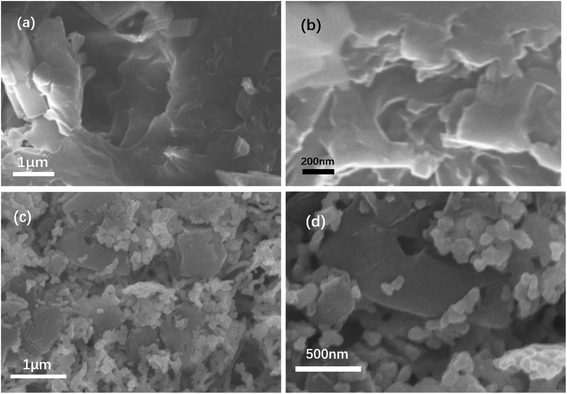
Fig. 1(a) and (b) show the structure of C3N5. The overall structure resembles a layered structure, with many layers converging into a large flat structure. In Fig. 1(c), the pure LaCoO3 prepared by the sol–gel method is a collection of many nanoscale ellipsoids. Each ellipsoidal particle has a uniform particle size, and the particles grow tightly together to form a two-dimensional nanolayered structure. From Fig. 1(d), we can observe that the LaCoO3 nanoparticle layer is divided into small pieces, and these small pieces grow vertically on the C3N5 nanosheets. This structure can contribute to the photocatalyst's absorption of light, the effective separation of electron and hole pairs and the migration of electrons and holes.3.2 X-ray diffraction (XRD) analysis
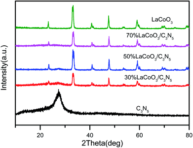
The crystal structures of pure LaCoO3, C3N5 and C3N5/LaCoO3 with different weight ratios were characterized by X-ray diffraction (XRD), as shown in Fig. 2. The X-ray powder diffraction characteristic curve of C3N5 shows a main peak at 27.4°, which can be attributed to the (0 0 2) crystal plane of C3N5.26 Each XRD diffraction peak of LaCoO3 is highly consistent with the crystal phase of JCPDS no. 84-0848, and there are no other diffraction peaks, indicating that the prepared sample is pure LaCoO3.27–32 Interestingly, after the combination of LaCoO3 and C3N5, the peak intensity of LaCoO3 is slightly reduced, but the characteristic peak of C3N5 cannot be clearly observed in the compound 70 wt% LaCoO3/C3N5, which may be due to its low crystallinity and lower amount of C3N5 doping.3.3 Transmission electron microscope (TEM) analysis
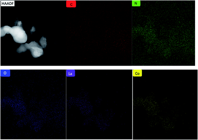
We used TEM and HRTEM to further explore the characteristics of the catalyst morphology, element composition, composition structure, and particle size. In Fig. 3(a), LaCoO3 shows an obvious ellipsoidal structure, and the particle size distribution range of the ellipsoid is 70–140 nm. In the HRTEM image of Fig. 3(b), we can observe that the spacing between adjacent lattice fringes is fixed, and the distance between adjacent lattice fringes can be obtained by measurement, that is, the plane spacing is approximately 0.27 nm, consistent with the crystal plane (1 0 4). As shown in Fig. 3(c) and (d), the C3N5 transmission electron microscope shows a clear layered structure, resembling laver. In Fig. 3(e) and (f), crystal lattice plane separation can be observed at the interface between LaCoO3 and C3N5. We can observe that the plane spacing between adjacent lattice fringes is approximately 0.27 nm, which is consistent with the crystal plane (1 0 4). Fig. 4 shows the element distribution image of 50% LaCoO3/C3N5. The distribution of different elements can be seen from the figure.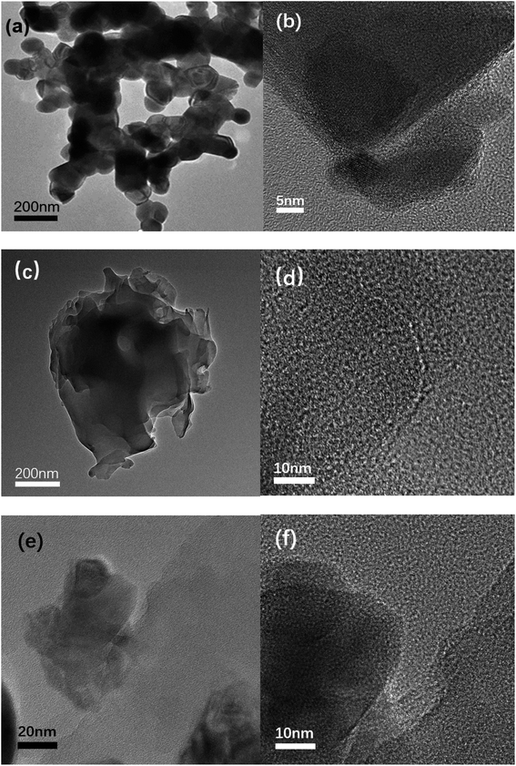 | ||
| Fig. 3 (a) TEM image and (b) HRTEM image of LaCoO3; (c) TEM image and (d) HRTEM image of C3N5; (e) TEM image of the LaCoO3/C3N5-50wt% composite material, (f) HRTEM image. | ||
3.4 X-ray photoelectron spectroscopy (XPS) analysis
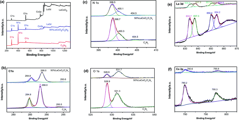
To determine the chemical state of the elements, the surface chemical composition and the interaction between LaCoO3 and C3N5, we performed XPS spectroscopic characterization, and the results are depicted in Fig. 5. All binding energies were corrected at 284.8 eV relative to the C 1s peak. The 50 wt% LaCoO3/C3N5 composite material is comprised of La, Co, O, C and N. The high-resolution C1s spectrum of pure C3N5 can be divided into two main peaks at approximately 284.8 eV and 288.0 eV. The C 1s peak at 284.8 eV is attributed to the C–C bond in sp3, and the peak at 288.0 eV is attributed to the sp2-type C![[double bond, length as m-dash]](https://www.rsc.org/images/entities/char_e001.gif) N bond. The high-resolution N 1s spectrum of the C3N5 sample shown in Fig. 5(c) can be divided into three main peaks. We specified the N 1s peak with the lowest binding energy (398.6 eV) for the C–N bond and the central peak (399.3 eV) for the sp2-type C
N bond. The high-resolution N 1s spectrum of the C3N5 sample shown in Fig. 5(c) can be divided into three main peaks. We specified the N 1s peak with the lowest binding energy (398.6 eV) for the C–N bond and the central peak (399.3 eV) for the sp2-type C![[double bond, length as m-dash]](https://www.rsc.org/images/entities/char_e001.gif) N bond.33–35 The peak with the largest binding energy is at 401.0 eV, which comes from the amorphous CN network. The nitrogen is surrounded by three carbons. However, a relatively strong sp2 peak is formed due to the N
N bond.33–35 The peak with the largest binding energy is at 401.0 eV, which comes from the amorphous CN network. The nitrogen is surrounded by three carbons. However, a relatively strong sp2 peak is formed due to the N![[double bond, length as m-dash]](https://www.rsc.org/images/entities/char_e001.gif) C–N type aromatic carbon, which constitutes C3N5, which is similar to the skeleton of carbon nitride. The HR-XPS spectrum of the core energy level in the N 1s region after peak splitting shows two peak components, located at 398.7 and 400.25 eV. The peak with a binding energy of 398.7 eV is attributed to the tertiary nitrogen N–(C)3 and the secondary C
C–N type aromatic carbon, which constitutes C3N5, which is similar to the skeleton of carbon nitride. The HR-XPS spectrum of the core energy level in the N 1s region after peak splitting shows two peak components, located at 398.7 and 400.25 eV. The peak with a binding energy of 398.7 eV is attributed to the tertiary nitrogen N–(C)3 and the secondary C![[double bond, length as m-dash]](https://www.rsc.org/images/entities/char_e001.gif) N–C nitrogen present in the aromatic ring structure, while the other peak at 400.2 eV is attributed to the presence of the main residues –NH2 and bridging CN
N–C nitrogen present in the aromatic ring structure, while the other peak at 400.2 eV is attributed to the presence of the main residues –NH2 and bridging CN![[double bond, length as m-dash]](https://www.rsc.org/images/entities/char_e001.gif) N in NC. The two XPS peaks located at 531.6 and 532.4 eV in the O 1s region are related to the adventitious oxygen and –OH groups adsorbed on the surface.
N in NC. The two XPS peaks located at 531.6 and 532.4 eV in the O 1s region are related to the adventitious oxygen and –OH groups adsorbed on the surface.
The spectrum of the pure LaCoO3 sample can be divided into three peaks: the one with the lowest binding energy (approximately 528.9 eV) is caused by lattice oxygen atoms on the surface, and the other (approximately 531.3 eV) is attributed to hydroxyl oxygen. The high-resolution O 1s spectrum of LaCoO3/C3N5 shows two main features at 528.9 eV and 531.7 eV, which are attributed to lattice oxygen atoms and hydroxyl oxygen on the surface, respectively. It is worth mentioning that the hydroxyl–oxygen bond peak position in the 50 wt% LaCoO3/C3N5 spectrum increased by 0.4 eV, which indicates that the chemical environment changed after being combined with LaCoO3. The typical high-resolution XPS La 3d spectrum of a 50 wt% LaCoO3/C3N5 sample shows two shoulder peaks. The vibration characteristics are located at 830–840 eV and 850–857 eV. The peaks can be divided into two distinct peaks at 833.7 eV and 837.3 eV and 850.4 eV and 854.2 eV, corresponding to the binding energies of La 3d5/2 and La 3d3/2, respectively, confirming the existence of La3+ in the crystal structure.28–30 For the high-resolution Co 2p spectrum of the 50 wt% LaCoO3/C3N5 sample. Fig. 5f, there are two main peaks at 780.2 eV and 795.3 eV, which are attributed to the typical shaking of the Co3+ structure at 787.2 eV.30,31 In short, the XPS results further proved that the LaCoO3/C3N5 composite material was successfully obtained.
3.5 Fourier infrared spectroscopy (FT-IR) analysis
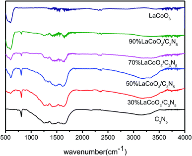
The FT-IR results of pure LaCoO3, C3N5 and LaCoO3/C3N5 with different mass ratios are shown in Fig. 6. For pure C3N5, the characteristic peaks at 1257.64, 1332.22, 1419.67 and 1637.63 cm−1 consistently have aromatic CN tensile vibration modes. The peak at approximately 3151.82 cm−1 is attributed to the tensile and flexural vibrations of N–H, which are derived from uncondensed terminal amino groups. In addition, the respiratory vibration of C3N5 has a characteristic absorption peak at 808.21 cm−1. The characteristic peak of LaCoO3 at 594.10 cm−1 is related to the bending and tensile vibration of Co–O, which corresponds to the perovskite structure. As the content of C3N5 in the LaCoO3 sample increases, the peak of the composite material gradually becomes sharper.33,343.6 UV-Vis diffuse reflectance spectrum (UV-Vis DRS) analysis
As shown in Fig. 7(a), the solid ultraviolet diffuse reflectance spectra of C3N5, LaCoO3 and 50 wt% LaCoO3/C3N5 composite materials were measured in the range of 250–600 nm by UV-Vis diffuse reflectance spectroscopy. It is worth noting that for pure LaCoO3, almost all ranges of light can be absorbed, showing excellent photoelectric properties. The LaCoO3/C3N5 composite material has similar absorption characteristics to LaCoO3. Compared with pure LaCoO3, the absorption edge of the LaCoO3/C3N5 composite shows a redshift, which indicates that the absorption of the LaCoO3/C3N5 composite can absorb more visible light by moving.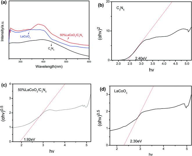 | ||
| Fig. 7 (a) Solid ultraviolet diffuse reflection of LaCoO3, C3N5 and LaCoO3/C3N5 composites; (b) C3N5 (c) LaCoO3/C3N5-50wt% (d) band gap energy (Eg) of LaCoO3. | ||
The band-gap energy (Eg) of the semiconductor is determined according to the Kubelka–Munk equation, as shown below:
| (αhυ)1/n = A(hυ − Eg) | (3.1) |
| ECB = χ − Eθ − 0.5Eg | (3.2) |
| EVB = ECB + Eg | (3.3) |
Among them, ECB and EVB represent the edge potentials of semiconductors CB and VB, respectively. χ is the electronegativity of the semiconductor. According to ref. 35–37, the χ values of pure LaCoO3/C3N5 can be obtained, which are approximately 4.59 eV and 5.64 eV, respectively. Eθ is the energy of a free electron with a hydrogen scale (∼4.5 eV relative to NHE), and Eg is the band-gap energy of the semiconductor.
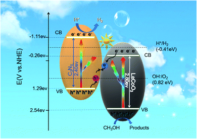
The values of χ, ECB, and EVB were calculated and are displayed in Table 1. The results show that the CB edge potential of C3N5 (−1.11 eV) is more negative than that of LaCoO3 (−0.26 eV), while the potential edge of VB LaCoO3 (2.54 eV) is more positive than that of C3N5 (1.29 eV).
| Sample | χ (eV) | ECB (eV) | EVB (eV) | Eg |
|---|---|---|---|---|
| LaCoO3 | 5.64 | −0.26 | 2.54 | 2.80 |
| C3N5 | 4.59 | −1.11 | 1.29 | 2.40 |
3.7 Brunauer–Emmett–Teller (BET) surface area and Barrett–Joyner–Halenda (BJH) pore size distribution analysis
The parameters of surface physicals structure of the prepared 50 wt% LaCoO3/C3N5 is shown in Table 2. The specific BET surface area of LaCoO3 and C3N5 were 62.5 and 56.2 m2 g−1, respectively. After the combination, the specific BET surface area of 50 wt% LaCoO3/C3N5 was 194.5 m2 g−1, which was 3.1 times higher than that of LaCoO3. The increase surface area of the combination of LaCoO3 and C3N5 was beneficial for increasing the active sites, which may improve catalytic activity.| Catalyst | BET surface area (m2 g−1) | Total pore volume (cm3 g−1) | Diameters of pore (nm) |
|---|---|---|---|
| LaCoO3 | 62.5 | 0.08 | 2.26 |
| C3N5 | 56.2 | 0.06 | 6.60 |
| 50 wt% LaCoO3/C3N5 | 194.5 | 0.21 | 2.40 |
3.8 Evaluation of photocatalytic performance
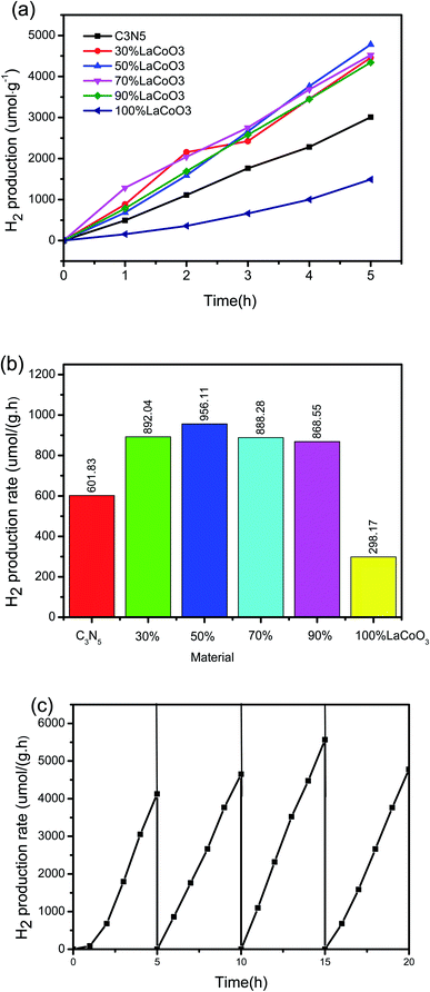
First, to evaluate the influence of light and catalyst on the experiment, a blank control experiment was carried out without light or a photocatalyst. Photocatalysis plays an important role in improving the efficiency of photocatalysis. Under these experimental conditions, the photolysis efficiency without a photocatalyst is negligible, which indicates that water containing 10% methanol is stable under visible light irradiation. To rule out the possibility of methanol reforming in the full spectrum, an anhydrous control experiment was carried out. We used 30 mL methanol and LaCoO3/50% C3N5 catalyst for the photocatalysis experiments, and the results showed that no hydrogen is produced. This indicates that the methanol in the experiment is a hole sacrificial agent that consumes holes to promote photocatalytic hydrogen production.Then, under full-spectrum (250–1200 nm) 300 W xenon lamp irradiation, synthetic LaCoO3, C3N5 and LaCoO3/C3N5 nanoparticles with different mass ratios were tested in an aqueous solution containing 10% (volume) methanol as a sacrificial reagent. As shown in Fig. 8(a) and (b), a gas chromatograph was used to detect H2 emissions. We conducted three parallel tests on all samples and calculated the average H2 escape rate, which can eliminate unexpected factors and obtain more convincing data. Obviously, LaCoO3, C3N5 and LaCoO3/C3N5 composites prepared with different mass ratios had different levels of hydrogen generation through photolysis. The H2 release rates of pure LaCoO3 and C3N5 were 298.17 μmol h−1 g−1 and 601.83 μmol h−1 g−1, respectively. The LaCoO3/C3N5-50wt% composite material has the largest photocatalytic activity, and the average hydrogen production per hour is 956.11 μmol h−1 g−1, which is 3.21 and 1.59 times that of LaCoO3 and C3N5, respectively. As shown in Fig. 8(c), even after four consecutive cycles, the photocatalytic efficiency did not show a significant loss, which shows that under the full-spectrum irradiation of xenon lamps, the heterojunction photocatalyst is engaged in the photocatalytic hydrolysis process and it is highly stable.
3.9 Electron spin resonance spectrum (ESR) analysis
To understand the mechanism more deeply, electron spin resonance (ESR) spectroscopy was applied. As shown in Fig. 9(a), after 10 minutes of exposure to the full-spectrum light of the xenon lamp, LaCoO3 and LaCoO3/C3N5-50wt% DMPO radical ˙OH signals can be observed, but there is no obvious sign of the pure C3N5 ˙OH signal. There is no DMPO-˙OH signal in C3N5 because ˙OH cannot be generated by holes in C3N5's VB . The observation of the DMPO-˙OH signal of the LaCoO3/C3N5-50wt% composite shows that the photogenerated holes stay in the VB of LaCoO3 and are not transferred to the VB of C3N5. In Fig 9(b), after exposure to the full-spectrum light of the xenon lamp for 10 minutes, the BMPO-O2− signal was observed for the composite sample of C3N5 and LaCoO3/C3N5-50wt% in the aqueous suspension. The O2− signal of LaCoO3 was observed. The results show that the photogenerated electrons in the composite samples of C3N5 and LaCoO3/C3N5-50wt% have sufficient reducing power to reduce O2 to form superoxide radical anions (O2−)
  .
.
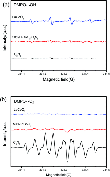 | ||
| Fig. 9 Use of pure C3N5, LaCoO3 and LaCoO3/C3N5-50wt% complex in (a) aqueous dispersion (for BMPO-O2−) and (b) aqueous dispersion (for DMPO-˙OH) in xenon lamp full-spectrum illumination. | ||
The EPR results show that photogenerated electrons and holes exist in C3N5 CB and LaCoO3 VB, respectively, and the charge transfer does not follow the conventional type II heterojunction mechanism. Therefore, it can be reasonably considered that the charge transfer path is the Z scheme mechanism. As semiconductors, LaCoO3 and C3N5 both have a band-gap. When the photon energy is equal to or greater than the forbidden bandwidth, the photogenerated electrons transition from the VB of C3N5 and LaCoO3 to CB and generate holes in the valence band (eqn (4)). Then, the electrons on LaCoO3 quickly recombine with the holes on C3N5 through the heterostructure (eqn (5)). The water and holes combine to produce hydrogen ions and oxygen (eqn (6)), and the hydrogen ions further combine with electrons on the conduction band of g-C3N4 to produce hydrogen (eqn (7)). The specific process of photocatalysis is as follows:
| LaCoO3/C3N5 + hv → e(LaCoO3)− + h(LaCoO3)+ + e(C3N5)− + h(C3N5)+ | (4) |
| e(LaCoO3)− + h(C3N5)+ → recombination | (5) |
| H2O +2h(LaCoO3)+ → ½O2 + 2H+ | (6) |
| 2e(C3N5)−+ 2H+ → H2 (g) | (7) |
4. Conclusion
In this paper, a new C3N5 material was synthesized using the construction of a heterojunction. Starting from the improvement of the semiconductor properties of LaCoO3 and C3N5, a composite photocatalyst was successfully prepared, and the photocatalytic activity was significantly improved. X-ray diffraction (XRD) and Fourier transform infrared spectroscopy (FT-IR), scanning electron microscope (SEM), transmission electron microscope (TEM), energy dispersive spectroscopy (EDS), X-ray photoelectron spectroscopy (XPS), ultraviolet visible diffuse reflectance spectroscopy (UV-Vis DRS), transient photocurrent response test, electron spin resonance spectrum (ESR) were applied for a series of characterizations. The characterization results showed that the LaCoO3 prepared by us exists as 50–100 nm nanospheres, and C3N5 has a layered structure. The apparent shape of the two was good, confirming the interaction between the heterostructure and the interface of the LaCoO3 nanoparticles and C3N5 nanosheets. In the photocatalytic water split test, 50 wt% LaCoO3/C3N5 showed the highest photocatalytic activity of 956.11 μmol h−1 g−1, which was 3.21 and 1.59 times that of LaCoO3 and C3N5, respectively. Even after four consecutive cycles, the photocatalytic efficiency did not show a significant loss, which indicates that the heterojunction photocatalyst is highly stable during the photocatalytic hydrolysis process under the full-spectrum irradiation of xenon lamps. For the LaCoO3/C3N5 photocatalytic water splitting system, a Z-type catalytic mechanism was proposed to explain the significant increase in photocatalytic activity. The novel and effective LaCoO3/C3N5 photocatalyst used in this work can be used in systems for water splitting or other photocatalytic applications. This work not only designs an inexpensive and efficient LaCoO3/C3N5 photocatalytic system for water splitting or other photocatalytic applications, but also provides ideas for constructing new material photocatalytic systems.Data availability
All data generated or analysed during this study are included in this published article.Author contributions
RW was the main author of the work, performed syntheses, electron microscopy and coordinated all characterization and catalytic studies. KZ is responsible for part of the synthesis work, XZ and FJ assisted with manuscript writing. All authors read and approved the final manuscript.Conflicts of interest
The authors listed in the manuscript have declared that they have no competing interests.Acknowledgements
This work was funded by Beijing Normal University.References
- H. Li, et al., Band structure engineering of polymeric carbon nitride with oxygen/carbon codoping for efficient charge separation and photocatalytic performance, J. Colloid Interface Sci., 2020, 564, 333–343 CrossRef CAS PubMed.
- X. Meng, et al., Carbon quantum dots assisted strategy to synthesize Co@NC for boosting photocatalytic hydrogen evolution performance of CdS, Chem. Eng. J., 2020, 389, 124432 CrossRef CAS.
- J. Si, et al., Colour centre controlled formation of stable sub-nanometer transition metal clusters on TiO2 nanosheet for high efficient H-2 production, Appl. Surf. Sci., 2020, 511, 145577 CrossRef CAS.
- M. Chen, et al., A novel Z-scheme AgBr/P-g-C3N4 heterojunction photocatalyst: Excellent photocatalytic performance and photocatalytic mechanism for ephedrine degradation, Appl. Catal., B, 2020, 266, 118614 CrossRef CAS.
- Z. Cai, et al., Acetate production from inorganic carbon (HCO3−) in photo-assisted biocathode microbial electrosynthesis systems using WO3/MoO3/g-C3N4 heterojunctions and Serratia marcescens species, Appl. Catal., B, 2020, 267, 118611 CrossRef CAS.
- Z. Gao, et al., Aminated flower-like ZnIn2S4 coupled with benzoic acid modified g-C3N4 nanosheets via covalent bonds for ameliorated photocatalytic hydrogen generation, Appl. Catal., B, 2020, 268, 118462 CrossRef CAS.
- A. S. Reddy and J. Kim, An efficient g-C3N4-decorated CdS-nanoparticle-doped Fe3O4 hybrid catalyst for an enhanced H-2 evolution through photoelectrochemical water splitting, Appl. Surf. Sci., 2020, 513, 145836 CrossRef CAS.
- M. Tahir, et al., Au-NPs embedded Z-scheme WO3/TiO2 nanocomposite for plasmon-assisted photocatalytic glycerol-water reforming towards enhanced H-2 evolution, Appl. Surf. Sci., 2020, 503, 144344 CrossRef CAS.
- H. Li, et al., Band structure engineering of polymeric carbon nitride with oxygen/carbon codoping for efficient charge separation and photocatalytic performance, J. Colloid Interface Sci., 2020, 564, 333–343 CrossRef CAS PubMed.
- M. Han, et al., Carbon Dots-Implanted Graphitic Carbon Nitride Nanosheets for Photocatalysis: Simultaneously Manipulating Carrier Transport in Inter- and Intralayers, Sol. RRL, 2020, 1900517 CrossRef CAS.
- W. Li, et al., Construction of Z-scheme and p–n heterostructure: Three-dimensional porous g-C3N4/graphene oxide-Ag/AgBr composite for high-efficient hydrogen evolution, Appl. Catal., B, 2020, 268, 118384 CrossRef CAS.
- P. Kumar, et al., C3N5: A Low Bandgap Semiconductor Containing an Azo-Linked Carbon Nitride Framework for Photocatalytic, Photovoltaic and Adsorbent Applications, J. Am. Chem. Soc., 2019, 141(13), 5415–5436 CrossRef CAS PubMed.
- S. Qi, et al, Metal-free highly efficient photocatalysts for overall water splitting: C3N5 multilayers, Nanoscale, 2020, 12, 306–315 RSC.
- D. Sun, et al., Metal-free boron doped g-C3N5 catalyst: Efficient doping regulatory strategy for photocatalytic water splitting, Appl. Surf. Sci., 2022, 601(11), 154186 CrossRef CAS.
- Y. Zhou, et al., A Multiple Structure-Design Strategy towards Ultrathin Niobate Perovskite Nanosheets with Thickness-Dependent Photocatalytic Hydrogen-Evolution Performance, Chem.–Asian J., 2017, 12(20), 2727–2733 CrossRef CAS PubMed.
- P. Kanhere and Z. Chen, A Review on Visible Light Active Perovskite-Based Photocatalysts, Molecules, 2014, 19(12), 19995–20022 CrossRef PubMed.
- B. Dong, et al., Development of Novel Perovskite-Like Oxide Photocatalyst LiCuTa3O9 with Dual Functions of Water Reduction and Oxidation under Visible Light Irradiation, Adv. Energy Mater., 2018, 8, 180166035 Search PubMed.
- J. Wang, et al., Double-hole-mediated coupling of anionic dopants in perovskite NaNbO3 for efficient solar water splitting, Int. J. Quantum Chem., 2019, 119, e2593014 Search PubMed.
- I. M. Nassar, et al., Facile Preparation of n-Type LaFeO3 Perovskite Film for Efficient Photoelectrochemical Water Splitting, ChemistrySelect, 2018, 3(3), 968–972 CrossRef CAS.
- M. Wang, et al., Hybrid density functional theory description of non-metal doping in perovskite BaTiO3 for visible-light photocatalysis, J. Solid State Chem., 2019, 280, 121018 CrossRef CAS.
- N. C. Hildebrandt, J. Soldat and R. Marschall, Layered Perovskite Nanofibers via Electrospinning for Overall Water Splitting, Small, 2015, 11(17), 2051–2057 CrossRef CAS PubMed.
- Y. Hu, et al., Layered perovskite oxides and their derivative nanosheets adopting different modification strategies towards better photocatalytic performance of water splitting, Renewable Sustainable Energy Rev., 2020, 119, 109527 CrossRef CAS.
- Y. Cen, et al., Optimized band gap and fast interlayer charge transfer in two-dimensional perovskite oxynitride Ba2NbO3N and Sr2NbO3/Ba2NbO3N bonded heterostructure visible-light photocatalysts for overall water splitting, J. Colloid Interface Sci., 2019, 546, 20–31 CrossRef CAS PubMed.
- J. Xu, et al., Perovskite Oxide LaNiO3 Nanoparticles for Boosting H-2 Evolution over Commercial CdS with Visible Light, Chem.–Eur. J., 2018, 24(69SI), 18512–18517 CrossRef CAS PubMed.
- K. Maeda, M. Eguchi and T. Oshima, Perovskite Oxide Nanosheets with Tunable Band-Edge Potentials and High Photocatalytic Hydrogen-Evolution Activity, Angew. Chem., Int. Ed., 2014, 53(48), 13164–13168 CrossRef CAS PubMed.
- S. N. Tijare, et al., Photocatalytic hydrogen generation through water splitting on nano-crystalline LaFeO3 perovskite, Int. J. Hydrogen Energy, 2012, 37(13), 10451–10456 CrossRef CAS.
- J. Guo, et al., Synthesis and characterization of Ag3PO4/LaCoO3 nanocomposite with superior mineralization potential for bisphenol A degradation under visible light, J. Alloys Compd., 2017, 696, 226–233 CrossRef CAS.
- R. Wang, et al., Z-Scheme LaCoO3/g-C3N4 for Efficient Full-Spectrum Light-Simulated Solar Photocatalytic Hydrogen Generation, ACS Omega, 2020, 5(47), 30373–30382 CrossRef CAS PubMed.
- R. R. Solís, et al., Synergism between peroxymonosulfate and LaCoO3-TiO2 photocatalysis for oxidation of herbicides. Operational variables and catalyst characterization assessment, J. Chem. Technol. Biotechnol., 2017, 92(8), 2159–2170 CrossRef.
- B. Dong, et al., Highly Efficient LaCoO3 Nanofibers Catalysts for Photocatalytic Degradation of Rhodamine B, J. Am. Ceram. Soc., 2010, 93(11), 3587–3590 CrossRef CAS.
- J. Guo, P. Li and Z. Yang, A novel Z-scheme g- C3N4/LaCoO3 heterojunction with enhanced photocatalytic activity in degradation of tetracycline hydrochloride, Catal. Commun., 2019, 122, 63–67 CrossRef CAS.
- H. Lan, et al., Microstructure of carbon nitride affecting synergetic photocatalytic activity: Hydrogen bonds vs. structural defects, Appl. Catal., B, 2017, 204, 49–57 CrossRef CAS.
- L. Wang, et al., Experimental study on the high performance of Zr doped LaCoO3 for solar thermochemical CO production, Chem. Eng. J., 2020, 389, 124426 CrossRef CAS.
- J. Luo, et al., Utilization of LaCoO3 as an efficient co-catalyst to boost the visible light photocatalytic performance of g-C3N4, Sep. Purif. Technol., 2018, 201, 309–317 CrossRef CAS.
- C. Belver, et al., Innovative W-doped titanium dioxide anchored on clay for photocatalytic removal of atrazine, Catal. Today, 2017, 280, 21–28 CrossRef CAS.
- Y. Hong, et al., In situ synthesis of direct solid-state Z-scheme V2O5/g-C3N4 heterojunctions with enhanced visible light efficiency in photocatalytic degradation of pollutants, Appl. Catal., B, 2016, 180, 663–673 CrossRef CAS.
- J. Zhu, et al., Enhancing CO2 catalytic activation and direct electroreduction on in situ exsolved Fe/MnOx nanoparticles from (Pr,Ba)2Mn2−yFeyO5+δ layered perovskites for SOEC cathodes, Appl. Catal., B, 2020, 268, 118389 CrossRef CAS.
| This journal is © The Royal Society of Chemistry 2022 |

