
 Open Access Article
 This Open Access Article is licensed under a Creative Commons Attribution-Non Commercial 3.0 Unported Licence
Interfacial configuration of heterogeneous NiFe–sulfide as a highly electrocatalytic selective oxygen evolution reaction electrode toward seawater electrolysis†
Yang Yang *,
Shengzhong Zhang,
Zhaoyang Song*,
Hongtao Wang,
Yanpeng Zhang,
Dequan Fan,
Fangzhou Hu,
Ying Yu and
Ying Zhang
*,
Shengzhong Zhang,
Zhaoyang Song*,
Hongtao Wang,
Yanpeng Zhang,
Dequan Fan,
Fangzhou Hu,
Ying Yu and
Ying Zhang
Sinopec Dalian Research Institute of Petroleum and Petrochemicals, Dalian 116045, Liaoning, P. R. China. E-mail: yangyang2019.fshy@sinopec.com
First published on 7th October 2022
Abstract
Seawater electrolysis for scalable hydrogen generation has attracted much attention due to the abundance of seawater in nature. However, it is severely impeded by the chlorine ions in seawater, which can cause corrosion and an undesirable competing reaction at the anode. So it is highly desirable to exploit a highly active, chlorine corrosion resistant and selective OER electrode for seawater splitting. Here, a heterogeneous NiFe–sulfide electrode is proposed to achieve an efficient OER process in alkaline seawater. Considering the 2D lamellar architecture with a rough surface and a considerable amount of micro voids, the dual electronic configuration of sulfur and iron, the strong synergistic effect between Ni and Fe at the atomic level and the interfacial engineering between the NiS/Ni3S2 phase and FeS phase at the nanoscale level, the Ni6Fe2S-0.05 M electrode exhibits predominant catalytic activity with an overpotential of 353 mV to reach 200 mA cm−2, superior long-term stability with 50 h accelerated stability test and higher selectivity toward the OER.
Introduction
Water electrolysis is regarded as an appealing alternative to generate high purity hydrogen. Compared with traditional water electrolysis, there are more chemical and engineering challenges in direct seawater splitting due to its variety of dissolved ions. The most serious challenge in seawater splitting is chlorine corrosion and the competing reactions between the desired oxygen reaction (OER) and the undesired chloride oxidation reaction (CER) at the anode, which have nearly thermodynamic equilibrium potentials.1–3 So it is imperative to design a highly active, outstanding chlorine corrosion resistant and selective OER electrode for seawater splitting. In particular, the difference in equilibrium potential between the two competing reactions and the hypochlorite formation are pH-dependent in alkaline base, with the result that the maximum thermodynamic potential difference value is around 480 mV at a high pH value.3–5 Hence, an alkaline environment is the best candidate for promoting selective OER toward seawater splitting.4–7 Based on these, it is urgent to develop an excellent electrode with superior activity for promoting the OER and inhibiting the CER simultaneously in alkaline solution.Recently, numerous efforts have been dedicated to exploit the transition metal-based materials as promising OER catalysts in alkalized seawater, including NiFe LDH,8,9 NiFeOOH,10 NiFeS,6 Co–FeP11 and so on. Among them, NiFe-based sulfides catalysts can exhibit predominant OER catalytic activity and selectivity because of their higher electrochemical conductivity and metallic property.12–14 Generally, constructing 2D nanosheets structure on the NF base can expose more accessible active sites via geometrical configuration, further boosting the electrochemical activity during the OER process.15,16 The OER activity can also be promoted by electronic modulation, which are achieved by introducing heteroatom.17,18 In particular, heterogeneous structure and interfacial regulation are regarded as an effective measure to manipulate the electronic arrangement, bringing out plentiful active sites and expedite the charge transfer efficiency.19–21 Xu et al. synthesized NiS/NiO@N–C NT/NFs electrode with ascendant activity towards OER, benefitting from the optimized electronic configuration, increased oxygen vacancies, rapid mass diffusion channels and remarkable structural robustness of the interfacial engineering and nanoarchitectonics.22 Ni et al. designed NiSe2/FeSe2 electrocatalyst with excellent OER activity, because of the local charge redistribution at the interface region induced by the self-driven electron transfer across the heterointerface between different phases, which is favorable for the adsorption of OH−.23
Herein, a simple strategy is proposed to synthesize a heterogeneous NiFe–sulfide electrode to resolve the multiple challenges of OER electrode in alkaline seawater. The 2D nanosheets with rough surface and micro voids can effectively promote the hydrophilicity of Ni6Fe2S/NF-0.05 M, thereby providing faster mass diffusion and creating more active sites to boost the OER process. The heterogeneous Ni6Fe2S/NF-0.05 M can provide intense synergistic effect between different metal active sites at atomic level, further stimulating the catalytic performance. Besides, the interfacial engineering between multiple heterogeneous phases can produce strong coupling interaction, which can tune the electronic structure to improve the adsorption of OH−, further facilitating the OER performance. Owning to the above geometrical construction and electronic regulation, the Ni6Fe2S-0.05 M electrode behaves excellent catalytic activity and selective OER performance than other counterparts.
Experimental methods
Preparation of NixFexS/NF-z M catalysts
The NixFexS/NF-z M composite catalysts were prepared by one-step electrodepositing method. The 1 × 2 cm Ni foam were first cleaned successively via sonication in acetone, ethanol, DI water and 3 M HCl solution to remove the surface oxide layer. x mM Ni(NO3)2·6H2O, y mM Fe(NO3)3·9H2O and z mM thiourea were dissolved in 200 mL DI water with stirring to obtain a homogeneous electrolyte (x = 8, 6, 4, 2, 0; y = 0, 2, 4, 6, 8; z = 0, 0.05, 0.1, 0.5, respectively). The electrodeposition process was carried out in a three-electrode system. NF (1 × 1 cm), Pt sheet and Ag/AgCl were used as the working electrode, counter electrode and reference electrode, respectively. The deposition process was untaken in −2.0 V vs. Ag/AgCl for 15 min, and the electrolyte was kept at 20 °C. The resulting electrode was washed with water and ethanol several times and dried in vacuum at 60 °C for 12 h to obtain the NixFexS/NF-z M composite.Material characterization
The morphology was performed by SEM (SU8020), TEM (JEM 2100 LaB6) and HRTEM (FEI Tecnai G2 F20). X-ray diffraction (XRD) characterizations were determined on a Rigaku D/MAX-2500. XPS measurements with a Thermo ESCALAB 250Xi analyzer were performed, and all XPS spectrums were calibrated with C 1s peak (284.6 eV) as binding energy reference. The presence of ClO− in alkalized electrolyte was detected by UV-vis (UV-1900).Electrochemical measurements
All electrochemical performances were evaluated by using an electrochemistry workstation (CHI 760E) with a standard three-electrode system. The NixFexS/NF-z M composite (1 × 1 cm) was used as the working electrode, Pt sheet and Hg/HgO electrode as the counter electrode and the reference electrode, respectively. Linear sweep voltammetry (LSV) measurements were conducted at 10 mV s−1. Cyclic voltammetry (CV) was performed between 0 and 0.6 V vs. Hg/HgO at a scan rate of 100 mV s−1. Electrochemical impedance spectroscopy (EIS) was tested under 0.6 V vs. Hg/HgO from the frequency of 105 to 0.01 Hz in electrolyte. Besides, the stability measurement was conducted by CV scanning of 5000 cycles from 0 to 0.5 V vs. Hg/HgO with a scan rate of 100 mV s−1, and chronoamperometry was performed at a current density from 10 to 100 mA cm−2. The electrochemical surface area (ECSA) was examined by the capacitance measurements in non-faradaic region (1.07–1.17 V vs. RHE) at different scan rates from 40 to 120 mV s−1. Half the slope of the differences about the current density at 1.12 V vs. RHE at various scan rates were calculated to get the values of Cdl. The ECSA could be calculated according to ECSA = Cdl/Cs × A, where Cs < 1 mF cm−2, and A is geometric area. All potentials were measured vs. Hg/HgO in this work, and can be converted into reversible hydrogen electrode (RHE) potential by ERHE = EHg/HgO + 0.9024.Results and discussion
As shown in Fig. 1, the NixFexS/NF-z M electrode was prepared via a simple one-step electrodeposition process. When the additional continuous voltage is applied in the electrolyte, a large amount of S2− was produced through the decomposition of thiourea in the solution, which can reduce the Ni2+ and Fe3+ ions in the solution. Then an amorphous NiFeS layer was gradually formed on the bare nickel foam. During the electrodeposition process, the following reactions will be occurred:24,25| CH4N2S + 2e− → CN− + NH4+ + S2− |
| Ni2+ + Fe3+ + xS2− → NiSx + FeSx |
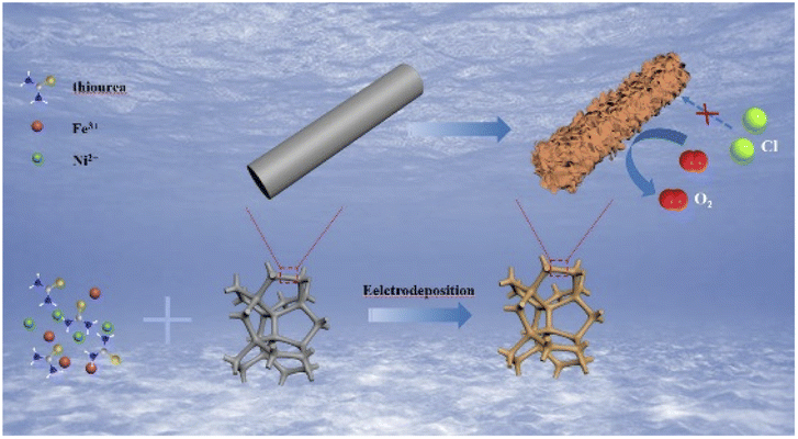 | ||
| Fig. 1 Schematic of fabrication of NixFexS/NF-z M composite catalysts. | ||
The morphologies of the samples are investigated by scanning electron microscope (SEM) and transmission electron microscopy (TEM). Fig. S2a and b† confirm the existence of small particle arrays on the NF substrate without Fe element. After the introduction of iron, the nanosheet arrays are gradually formed with rough surface and considerable amount of micro voids, which are in favor of improving the hydrophilicity of the prepared electrodes to accelerate mass diffusion in electrolyte and create more electrocatalytic active sites accessible (Fig. 2b and S2†).26 Moreover, it is notable that the nanosheets structure will reunion with excessive iron content, indicating that only appropriate iron content can promote the formation of nanosheet arrays on the NF substrate. The element mapping results (Fig. 2b) confirm the presence of Ni, Fe, S and N with uniform distribution, proving the successful doping of Fe and S. TEM is further carried out to reveal the microstructure of Ni6Fe2S/NF-0.05 M (Fig. 2c and d), and the corresponding high-resolution TEM (HRTEM) is conducted to demonstrate the interfacial region between NiS/Ni3S2 phase and FeS phase. As shown in Fig. 2e, the lattice fringes with spacing of 0.270 nm, 0.222 nm, 0.204 nm and 0.238 nm can be well indexed to (200) plane of FeS phase, (211) plane of NiS phase, (202) plane of Ni3S2 phase, (003) plane of Ni3S2 phase, respectively. Meanwhile, the heterojunction interface can also be identified in Fig. 2e, caused by mismatch of NiS/Ni3S2 phase and FeS phase, as marked by the dashed line. It is worth noting that interfacial heterogeneous NiFe–sulfides can provide more electrochemical active sites to accelerate dissociative adsorption of water, subsequently division of the H–OH bond to promote the kinetics for water electrolysis. In addition, the influence of sulfur content on morphological change is also evaluated and shown in Fig. S3,† indicating that sulfur can promote the formation of numerous lamellae. However, small particles will gradually form on the substrate with excessive amount of sulfur, suggesting that optimized 2D nanosheets arrays on NF base with a large number of micro-voids can be realized with only suitable sulfur content.
 | ||
| Fig. 2 (a) XRD patterns of the samples, (b) SEM images and the corresponding mapping of Ni6Fe2S/NF-0.05 M collected on SEM, (c and d) TEM images and (e) HR-TEM image of Ni6Fe2S/NF-0.05 M. | ||
X-ray diffraction (XRD) is employed to investigate the chemical structure of the as-prepared catalysts. As shown in Fig. 2a, Ni6Fe2S/NF-0.05 M possess similar diffraction peaks location and weaker intensity of the diffraction peaks than the NF substrate, suggesting the low crystallinity of Ni6Fe2S/NF-0.05 M. Moreover, the catalysts powder are obtained via sonication stripping to further reveal its amorphous structure. As displayed in Fig. S1a,† there is no obvious XRD diffraction peaks of the catalyst powder, consistent with the results of integrated electrode, illustrating poor crystallinity structure of Ni6Fe2S/NF-0.05 M. It is noteworthy that NiFe catalysts with weakly crystalline structure can further enhance the electrocatalytic activity, benefitted from their structure flexibility and more coordinative unsaturated sites, with the result that reactants can be adsorbed more easily than those of the crystalline catalysts.27,28 Furthermore, the XRD patterns of NixFexS/NF-z M with various ratios of Ni to Fe are also shown in Fig. S1b,† which possess similar characteristic peaks with the increase of Fe content. Notably, there will be a slight change of the diffraction peaks with the gradually increasing doping of iron, induced by the replacement of Ni2+ by Fe3+ with smaller atomic radius.26 The partial substitute of active sites can strengthen the synergism interaction between Ni and Fe at atomic level and the coupling interaction between different heterogeneous phases, which are favorable for the OER process.
As shown in Fig. 3 and S4,† the X-ray photoelectron spectroscopy (XPS) is utilized to examine the surface chemical states on the prepared samples. For Ni 2p spectrum, the binding energy of the peaks located at 856 eV and 874 eV can be ascribed to Ni 2p3/2 and Ni 2p1/2, accompanied with the satellite peaks at 868 eV and 880 eV, respectively.29,30 The Fe 2p peaks at 707 eV, 712 eV, 716 eV and 725 eV can be originated from Fe2+ 2p3/2, Fe3+ 2p3/2, Fe2+ 2p1/2, and Fe3+ 2p1/2, respectively.29,31 There are two binding energies in the O 1s spectrum, which can be assigned to metal–OH and metal–O, respectively.32,33 After sulfuration, the binding energies of characteristic peaks for S 2p spectrum are shown in Fig. 3c, corresponding to the M–S, S2−, and S–O, respectively, demonstrating the successful doping of sulfur.30,34 The phenomenon is also confirmed by the results of Ni 2p, Fe 2p and O 1s spectrum. The binding energies for Ni 2p and Fe 2p shift slightly to lower binding energy after the introduction of sulfur, showing that the doping of sulfur can change the electron cloud density around Ni and Fe center (Fig. 3a and b). As shown in Fig. 3d, the intensity of two characteristic peaks for O 1s of Ni6Fe2S/NF-0.05 M are significantly weaker than those for Ni6Fe2S/NF-0 M. In general, the XPS results before and after sulfuration can further prove the coupling interaction between different metal active center and sulfur, which can promote the OER performance in alkaline seawater. In addition, the synergistic interaction between Ni and Fe is also investigated by XPS. It is discovered that the binding energies for Ni 2p are negatively shifted with the introduction of iron, and the binding energies for Fe 2p are negatively shifted with increasing Ni (Fig. S4†), caused by a variation of coordination bonds and electronic structure, which can effectively heighten the electrocatalytic activity.
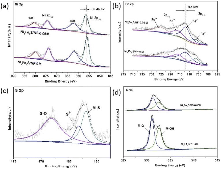 | ||
| Fig. 3 XPS spectra of (a) Ni 2p, (b) Fe 2p, (c) S 2p, (d) O 1s for the samples before and after sulfuration. | ||
As shown in Fig. 4a, the selective OER activity of the prepared samples are evaluated in 4.0 M NaOH and 1 M NaCl solution by linear sweep voltammetry (LSV). The peaks at around 1.43 V are observed in LSV curves, which can be ascribed to the oxidation of Ni2+ to Ni3+.26,35 In order to avoid the interference of oxidation peaks, the overpotential at 200 mA cm−2 is chosen to be the activity indicator. Compared with the samples with other ratios of Ni to Fe, the overpotentials required to reach the current density of 200 mA cm−2 and 400 mA cm−2 for Ni6Fe2S/NF-0.05 M are 353 mV and 505 mV, which are lower than those for Ni8Fe0S/NF-0.05 M (473 mV and 657 mV), Ni4Fe4S/NF-0.05 M (401 mV and 583 mV), Ni2Fe6S/NF-0.05 M (393 mV and 574 mV), Ni0Fe8S/NF-0.05 M (394 mV and 578 mV), which are also comparable with reported catalysts (Table S1†). The results indicate that proper iron doping can significantly facilitate the OER performance, owing to the strong synergy between Ni and Fe, the conductivity promotion and faster charge transfer from Fe sites to Ni active centers,26 and the interfacial configuration between multiple heterogeneous phases, agreement with previous characterization results. In addition, the electrodes with various amount of sulfur are also evaluated and shown in Fig. S5.† The Ni6Fe2S/NF-0.05 M electrode with optimized sulfur content exhibits distinctive OER performance, which can be attributed to following reasons. Firstly, the 2D lamellar structure with rough surface and plenty micro-void can provide more active sites available, the improvement of hydrophilic property and more mass transfer channels, therefore accelerating the catalytic process. Secondly, sulfur modulation at electronic and atomic level can assign their dispersive electrons to the empty orbits of NiFe sites to strengthen the covalent interaction between NiFe and S,36 thereby resulting in the improvement for OER process, in agreement with SEM results.
 | ||
| Fig. 4 (a) LSV polarization curves, (b) overpotentials of 200 mA cm−2 and 400 mA cm−2, (c) Tafel slopes, (d) EIS Nyquist plots at a value of 0.58 V, (e) stability tests for Ni6Fe2S/NF-0.05 M after 5000 potential cycles, and (f) chronoamperometry measurement of Ni6Fe2S/NF-0.05 M from 10 mA cm−2 to 100 mA cm−2 in 4.0 M NaOH and 1.0 M NaCl solution. | ||
To further study the OER kinetics, the Tafel plots derived from LSV curves are investigated. The Tafel slope of Ni6Fe2S/NF-0.05 M is 104 mV dec−1, which is lower than those of other samples, indicating a faster electron transfer process between electrode and electrolyte caused by the unique geometric structure with micro-voids and the promotion of robust interfacial engineering between multiple heterostructure, in good agreement with the LSV results (Fig. 4c and S5c†). Besides, electrochemical impedance spectrum (EIS) measurements are tested to get a more profound understanding of OER kinetics. The EIS value for Ni6Fe2S/NF-0.05 M is 0.9 Ω, smaller than those of other counterparts shown in Fig. 4d, certificating a lower ionic and transport resistance of the Ni6Fe2S/NF-0.05 M electrode as well, which is beneficial for OER process towards alkalized seawater splitting.
The accelerated stability is investigated by CV scanning for 5000 cycles and long-term chronoamperometry. The LSV curves shows no obvious degradation after 5000 cycles in alkaline chloride solution (Fig. 4e). The current densities of Ni6Fe2S/NF-0.05 M electrode can be well maintained at a current density from 10 mA cm−2 to 100 mA cm−2 (Fig. 4f). Simultaneously, the time-dependent potential curve of Ni6Fe2S/NF-0.05 M also exhibits negligible change at a high current density of 100 mA cm−2 after more than 50 hours test (Fig. S6†). Moreover, the durability test is conducted in alkaline seawater to further probe the structural stability (Fig. S6†). There is a tiny recession of LSV curves after 5000 CV cycles scanning test in alkaline seawater, caused by other dissolved ions in seawater, implying that there are still many challenges to overcome for the further development of the seawater electrolysis technology.
To deeply explore the intrinsic activity of the prepared samples, the electrochemical surface area (ECSA) is conducted, which is positive correlated with the double layer capacitance (Cdl). As shown in Fig. S7,† the Cdl value of Ni6Fe2S/NF-0.05 M is 12.77 mF cm−2, higher than those of Ni6Fe2S/NF-0.05 M (9.39 mF cm−2) and Ni0Fe8S/NF-0.05 M (11.72 mF cm−2), further proving that the rough surface caused by dual element doping, the synergistic interaction between Ni and Fe at the atom level and the strong coupling interaction between NiS/Ni3S2 phase and FeS phase across interfacial region are beneficial to provide more active sites available.
In order to get further insight into the electrocatalytic selective OER performance, the solution after reaction with specific condition are analyzed by UV-vis characterization. As revealed in Fig. 5, the peak located at around 290 nm can be ascribed to the ClO−. There are no peaks of the samples after 2 h chronocurrent test under various potentials in alkaline seawater, suggesting its excellent resistance to chloride corrosion of Ni6Fe2S/NF-0.05 M. This result deeply proves that the interfacial engineering between heterogeneous NiS/Ni3S2 phase and FeS phase can improve the adsorption of OH−, resulting in the significant improvement of selectivity towards OER in alkalized seawater electrolysis.
 | ||
| Fig. 5 UV curves for alkaline chloride solution under various potentials. | ||
Above all, the outstanding OER performance of Ni6Fe2S/NF-0.05 M can be summarized to the following factors. (1) The 2D nanosheets with rough surface and considerable amount of micro-voids can effectively promote the hydrophilicity of Ni6Fe2S/NF-0.05 M, resulting in faster mass diffusion in electrolyte and generating more active sites accessible to further ameliorate the OER activity. (2) The heterostructure of Ni6Fe2S/NF-0.05 M with optimal Ni/Fe/S ratio can provide strong synergistic effect between Fe and Ni at atomic level and robust coupling interaction between FeS and NiS species at nanoscale level, which are beneficial for the improvement of OER performance. (3) The interfacial regulation between NiS/Ni3S2 phase and FeS phase can optimize the electronic engineering to provide more active vacancies and rapid mass diffusion channels, thus leading the promotion of adsorption of OH− to improve the catalytic activity and selective OER performance.
Conclusions
In conclusion, a heterogeneous Ni6Fe2S/NF-0.05 M is successfully synthesized through a simple one-step electrodeposition process. Based on the improvement measures of geometrical construction and electronic regulation, Ni6Fe2S/NF-0.05 M exhibits an outstanding OER activity with an overpotential of 353 mV to reach 200 mA cm−2, excellent long-term stability with 50 h accelerated stability test and higher selectivity. Detailed structural and electrochemical characterizations confirm the OER performance, benefitting from the unique 2D lamellar architecture with micro-void, dual electronic configuration of sulfur and iron, the interfacial engineering between NiS/Ni3S2 phase and FeS phase, and the strong synergism effect between multiple heterogenous phases, exposing more active sites and micro-void to accelerate the transport of ions and benefit the rapid diffusion of the generated gas, thereby improving the catalytic activity toward OER. These findings can provide a feasible measure to effectively resolve the multiple challenges of OER electrode in alkaline seawater.Conflicts of interest
There are no conflicts to declare.Acknowledgements
This work is financially supported by SINOPEC (No. 121054).References
- J. Chang, G. Wang, Z. Yang, B. Li, Q. Wang, R. Kuliiev, N. Orlovskaya, M. Gu, Y. Du, G. Wang and Y. Yang, Adv. Mater., 2021, 33, e2101425 CrossRef PubMed.
- Z. Song, K. C. Wang, Q. Sun, L. Zhang, J. Li, D. Li, P. W. Sze, Y. Liang, X. Sun, X. Z. Fu and J. L. Luo, Adv. Sci., 2021, 8, 2100498 CrossRef CAS PubMed.
- C. Wang, M. Zhu, Z. Cao, P. Zhu, Y. Cao, X. Xu, C. Xu and Z. Yin, Appl. Catal., B, 2021, 291, 120071 CrossRef CAS.
- H. J. Song, H. Yoon, B. Ju, D.-Y. Lee and D.-W. Kim, ACS Catal., 2019, 10, 702–709 CrossRef.
- J. Li, Y. Liu, H. Chen, Z. Zhang and X. Zou, Adv. Funct. Mater., 2021, 31, 2101820 CrossRef CAS.
- Y. Kuang, M. J. Kenney, Y. Meng, W.-H. Hung, Y. Liu, J. E. Huang, R. Prasanna, P. Li, Y. Li and L. Wang, Proc. Natl. Acad. Sci. U. S. A., 2019, 116, 6624–6629 CrossRef CAS.
- P. Li, S. Wang, I. A. Samo, X. Zhang, Z. Wang, C. Wang, Y. Li, Y. Du, Y. Zhong, C. Cheng, W. Xu, X. Liu, Y. Kuang, Z. Lu and X. Sun, Research, 2020, 2020, 2872141 CAS.
- S. Dresp, T. Ngo Thanh, M. Klingenhof, S. Brückner, P. Hauke and P. Strasser, Energy Environ. Sci., 2020, 13, 1725–1729 RSC.
- Q. Tu, W. Liu, M. Jiang, W. Wang, Q. Kang, P. Wang, W. Zhou and F. Zhou, ACS Appl. Energy Mater., 2021, 4, 4630–4637 CrossRef CAS.
- Y. S. Park, J. Lee, M. J. Jang, J. Yang, J. Jeong, J. Park, Y. Kim, M. H. Seo, Z. Chen and S. M. Choi, J. Mater. Chem. A, 2021, 9, 9586–9592 RSC.
- S. Wang, P. Yang, X. Sun, H. Xing, J. Hu, P. Chen, Z. Cui, W. Zhu and Z. Ma, Appl. Catal., B, 2021, 297, 120386 CrossRef CAS.
- Z. Zhang, Z. Li and L. Yin, New J. Chem., 2018, 42, 1467–1476 RSC.
- G. B. Shombe, M. D. Khan, C. Zequine, C. Zhao, R. K. Gupta and N. Revaprasadu, Sci. Rep., 2020, 10, 1–14 CrossRef.
- Y. Zu, Z. Guo, J. Zheng, Y. Hui, S. Wang, Y. Qin, L. Zhang, H. Liu, X. Gao and L. Song, Chem. Eng. J., 2020, 380, 122319 CrossRef CAS.
- Y. Li, H. Zhang, M. Jiang, Q. Zhang, P. He and X. Sun, Adv. Funct. Mater., 2017, 27, 1702513 CrossRef.
- Y. Song, B. Xu, T. Liao, J. Guo, Y. Wu and Z. Sun, Small, 2021, 17, 2002240 CrossRef CAS PubMed.
- C. Xuan, J. Wang, W. Xia, J. Zhu, Z. Peng, K. Xia, W. Xiao, H. L. Xin and D. Wang, J. Mater. Chem. A, 2018, 6, 7062–7069 RSC.
- L. Shen, Q. Zhang, J. Luo, H. C. Fu, X. H. Chen, L. L. Wu, H. Q. Luo and N. B. Li, ACS Sustainable Chem. Eng., 2021, 9, 5963–5971 CrossRef CAS.
- Y. Li, G. Tang, Y. Wang, Y. Chai and C. Liu, ACS Omega, 2022, 7(16), 13687–13696 CrossRef CAS.
- Z. W. Gao, T. Ma, X. M. Chen, H. Liu, L. Cui, S. Z. Qiao, J. Yang and X. W. Du, Small, 2018, e1800195 CrossRef PubMed.
- D. Jiang, S. Xu, B. Quan, C. Liu, Y. Lu, J. Zhu, D. Tian and D. Li, J. Colloid Interface Sci., 2021, 591, 67–75 CrossRef CAS.
- T. Li, T. Lu, Y. Li, J. Yin, Y. Tang, M. Zhang, H. Pang, L. Xu, J. Yang and Y. Zhang, Chem. Eng. J., 2022, 428, 131094 CrossRef CAS.
- S. Ni, H. Qu, Z. Xu, X. Zhu, H. Xing, L. Wang, J. Yu, H. Liu, C. Chen and L. Yang, Appl. Catal., B, 2021, 299, 120638 CrossRef CAS.
- C.-W. Su, J.-M. Li, W. Yang and J.-M. Guo, J. Phys. Chem. C, 2014, 118, 767–773 CrossRef CAS.
- J. Huo, J. Wu, M. Zheng, Y. Tu and Z. Lan, Electrochim. Acta, 2015, 180, 574–580 CrossRef CAS.
- Q. Zhou, Y. Chen, G. Zhao, Y. Lin, Z. Yu, X. Xu, X. Wang, H. K. Liu, W. Sun and S. X. Dou, ACS Catal., 2018, 8, 5382–5390 CrossRef CAS.
- G. Liu, M. Wang, Y. Wu, N. Li, F. Zhao, Q. Zhao and J. Li, Appl. Catal., B, 2020, 260, 118199 CrossRef CAS.
- C. Xiao, Y. Li, X. Lu and C. Zhao, Adv. Funct. Mater., 2016, 26, 3515–3523 CrossRef CAS.
- X. Luan, H. Du, Y. Kong, F. Qu and L. Lu, Chem. Commun., 2019, 55, 7335–7338 RSC.
- Y.-K. Hsu, A. Mondal, Y.-Z. Su, Z. Sofer, K. S. Anuratha and J.-Y. Lin, Appl. Surf. Sci., 2022, 579, 151923 CrossRef CAS.
- X. Wu, H. Liu, F. Li, L. Lu, W. Li, L. Feng and L. Sun, Int. J. Hydrogen Energy, 2021, 46, 38992–39002 CrossRef CAS.
- L. Yu, L. Wu, B. McElhenny, S. Song, D. Luo, F. Zhang, Y. Yu, S. Chen and Z. Ren, Energy Environ. Sci., 2020, 13, 3439–3446 RSC.
- Q. Xu, W. Gao, M. Wang, G. Yuan, X. Ren, R. Zhao, S. Zhao and Q. Wang, Int. J. Hydrogen Energy, 2020, 45, 2546–2556 CrossRef CAS.
- F. Jing, Q. Lv, J. Xiao, Q. Wang and S. Wang, J. Mater. Chem. A, 2018, 6, 14207–14214 RSC.
- G. Zhang, Y.-S. Feng, W.-T. Lu, D. He, C.-Y. Wang, Y.-K. Li, X.-Y. Wang and F.-F. Cao, ACS Catal., 2018, 8, 5431–5441 CrossRef CAS.
- B. Q. Li, S. Y. Zhang, C. Tang, X. Cui and Q. Zhang, Small, 2017, 13, 1700610 CrossRef.
Footnote |
| † Electronic supplementary information (ESI) available. See https://doi.org/10.1039/d2ra04253c |
| This journal is © The Royal Society of Chemistry 2022 |