 Open Access Article
Microflower-like Co9S8@MoS2 heterostructure as an efficient bifunctional catalyst for overall water splitting†
Chaohai Pang‡
 *ab,
Xionghui Ma‡
 ab,
Yuwei Wuab,
Shuhuai Li
 *ab,
Zhi Xuab,
Mingyue Wangab and
Xiaojing Zhu*c
aAnalysis and Test Center, Chinese Academy of Tropical Agricultural Sciences, Hainan Provincial Key Laboratory of Quality and Safety for Tropical Fruits and Vegetables, Key Laboratory of Quality and Safety Control for Subtropical Fruit and Vegetable, Ministry of Agriculture and Rural Affairs Haikou, 571101, China. E-mail: 18389859589@163.com; happylishuhuai@163.com
bKey Laboratory of Tropical Fruits and Vegetables Quality and Safety for State Market Regulation, Haikou, 570311, China
cResearch Center of Advanced Chemical Equipment, Chemistry and Chemical Engineering Guangdong Laboratory, Shantou 515041, China. E-mail: xiaoj_zhu@163.com
First published on 15th August 2022
Abstract
The development of a distinguished and high-performance catalyst for H2 and O2 generation is a rational strategy for producing hydrogen fuel via electrochemical water splitting. Herein, a flower-like Co9S8@MoS2 heterostructure with effective bifunctional activity was achieved using a one-pot approach via the hydrothermal treatment of metal-coordinated species followed by pyrolysis under an N2 atmosphere. The heterostructures exhibited a 3D interconnected network with a large electrochemical active surface area and a junctional complex with hydrogen evolution reaction (HER) catalytic activity of MoS2 and oxygen evolution reaction (OER) catalytic activity of Co9S8, exhibiting low overpotentials of 295 and 103 mV for OER and HER at 10 mA cm−2 current density, respectively. Additionally, the catalyst-assembled electrolyser provided favourable catalytic activity and strong durability for overall water splitting in 1 M KOH electrolyte. The results of the study highlight the importance of structural engineering for the design and preparation of cost-effective and efficient bifunctional electrocatalysts.
Introduction
Owing to increasing energy demands and the unreasonable use of fossil fuels, there is an urgent need for clean and sustainable energy.1 The development of sustainable, inexpensive, eco-friendly, and highly efficient energy resources is one of the most effective approaches for resolving environmental and energy problems. Electrocatalytic water splitting to H2 and O2 is an attractive and highly potential technology for renewable energy production because water resources are abundant and no carbon is involved.2,3 The catalytic performance of precious catalysts, such as platinum4 and RuO2/IrO2,5–7 remains unmatched for electrocatalytic water splitting. Nevertheless, prohibitive cost, scarcity, and poor durability of these precious catalysts restrain their large-scale practical applications.8–10 Consequently, it is tremendously desirable to prepare high-efficiency and low-cost bifunctional catalysts for overall water splitting.11,12Recently, various investigations have shown that MoS2 is a promising candidate for the HER.13–16 However, MoS2 also has drawbacks such as covering of active sites, poor conductivity, and low OER performance.17–19 In contrast, transition metal sulphides and oxides of Co such as Co3S4,20,21 Co9S8,22–24 Co4O4,25 and LaCoO326,27 exhibit higher conductivity and efficient electrocatalytic performance for the OER, but their HER performance is unsatisfactory. Some studies have reported that the electronic structure of MoS2 can be modulated and optimised by doping with transition metals (e.g. Ni and Co) to achieve enhanced catalytic activity.28,29 Consequently, the integration of OER-active Co9S8 and HER-active MoS2 into the same material is a judicious strategy for fabricating suitable bifunctional electrocatalysts for water electrolysis.30
Several studies are currently focusing on the fabrication of bifunctional electrocatalysts comprising MoS2 and Co9S8 nanocomposites to achieve efficient overall water splitting.23,31–35 Cao et al.17 prepared a uniform Co9S8@MoS2 heterostructure using a simple process that combined solvothermal treatment with pyrolysis. In an alkaline solution, the proposed heterostructure showed a current density of 10 mA cm−2 for the HER and OER under overpotentials of 143 and 340 mV, respectively. Meanwhile, for overall water splitting, only a voltage of 1.67 V was demanded at 10 mA cm−2 in alkaline electrolyser. Du et al.36 designed and prepared a multicomponent Co9S8@MoS2 nanohybrid derived from cobalt-doped polyoxometalate using a one-pot calcination technique. This nanohybrid exhibited a smallish overpotential (230 mV) for the OER but a relatively high overpotential (239 mV) for the HER at 10 mA cm−2. Despite these advances, it is necessary to develop a novel and simple route to obtain cost-efficient bifunctional electrocatalysts with unique structures for the sake of enrichment of material preparation database, remarkable performance, and robust stability.
In this study, a bifunctional hybrid electrocatalyst comprising Co9S8 and MoS2 with the structural merits of a flower-like morphology was synthesised using a facile hydrothermal treatment with metal salts and the strongly coordinating ligand ethylenediamine and formaldehyde, followed by annealing. A three-dimensionally interconnected network structure with the Co9S8 microflower tightly attached to the MoS2 nanoflakes was materialised. The obtained Co9S8@MoS2 heterostructure was further explored as bifunctional electrocatalysts for HER and OER. Compared with the sole component of Co9S8 and MoS2, the prepared Co9S8@MoS2 microflowers displayed low overpotentials of 295 and 103 mV to achieve a current density of 10 mA cm−2 in alkaline electrolyte for the HER and OER, respectively, as well as a low overpotential (1.64 V) for overall water splitting at a current density of 10 mA cm−2 when employed as a two-electrode assembly device. The results in this work highlight the importance of structural engineering for the design and preparation of low-cost, efficient, and bifunctional electrocatalysts.
Results and discussion
The two-step synthesis method for Co9S8@MoS2 is illustrated in Fig. 1a. First, a flower-like composite precursor was formed by hydrothermal treatment of the metal salts in the presence of the strongly coordinating ligands thiourea, ethylenediamine, and formaldehyde.37 Subsequently, the sample was pyrolyzed in a tube furnace under a nitrogen ambiance at 500 °C to obtain the Co9S8@MoS2 heterostructure. The SEM images in Fig. 1b reveal that Co9S8@MoS2 comprised flower-like structures, which is uniform spherical with a regular size of ∼2.0 μm. In contrast, MoS2 comprised aggregated nanosheets with no clear macroporous structures (Fig. 1c). Co9S8 exhibits a flower-like morphology similar to that of Co9S8@MoS2, but unexpected spherical particles are also present on the surface of the Co9S8 microflowers, indicative that the addition of Mo salt allows the surface coverage and keep the structural integrity (Fig. 1d). These morphology differences demonstrate the success assemble of MoS2 and Co9S8 in the one flower-like component. Notably, the intact flower-like morphology of the Co9S8@MoS2 composite implies that the formation of spherical particles was hindered by the surface coverage of MoS2 nanosheets during carbonisation. Furthermore, the porous texture of Co9S8@MoS2 can provide abundant channels for the release of electrolyte and gaseous products.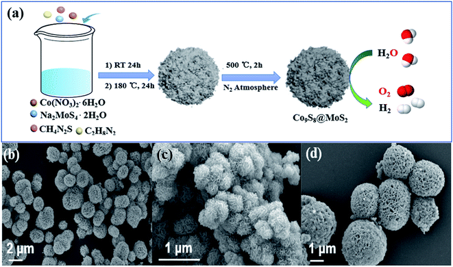 | ||
| Fig. 1 (a) Schematic illustration of the fabrication of a typical sample Co9S8@MoS2 as a bifunctional electrocatalyst for water splitting. SEM images for Co9S8@MoS2 (b), MoS2 (c) and Co9S8 (d). | ||
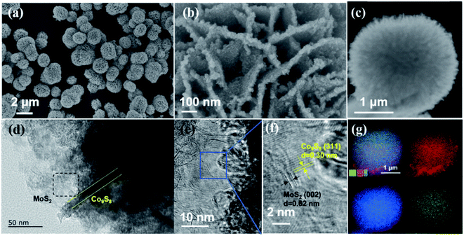
The Co9S8@MoS2 has a porous flower-like morphology comprising interconnected flakes with a thickness of approximately 20 nm (Fig. 2a and b). Fig. 2c shows that the Co9S8@MoS2 particles comprised a dense inner Co9S8 layer and outer MoS2 nanosheets. Lattice fringes with spacings of 0.30 and 0.62 nm are clearly visible in the High-Resolution TEM (HRTEM) images, which correspond to the (311) plane of Co9S8 and the (002) plane of MoS2. In addition, the lattice fringes between Co9S8 and MoS2 are clearly observed (Fig. 2e and f). Elemental mapping (Fig. 2g) confirms that Mo, S, and Co are evenly distributed in the Co9S8@MoS2 heterostructure.
The three-dimensional (3D) flower-like Co9S8@MoS2 heterostructural spheres are assembled by the interconnections of heterostructural 2D nanosheets, which not only prevent the restack/aggregation of nanosheets but also provide hierarchical three-dimensional porous structures, allowing the well-exposed interfaces and favourable diffusion channels and manifesting excellent electrocatalytic performance for overall water.
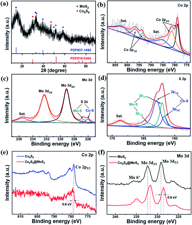
To obtain in-depth understanding of the elemental states and phase structures of the Co9S8@MoS2 composite, XPS and powder XRD investigations were performed. The XRD pattern of Co9S8@MoS2 in Fig. 3a exhibits characteristic diffraction peaks at 14.2°, 32.8°, 33.8°, 39.6°, 49.5°, and 58.9°, which can be attributed to the (002), (100), (101), (102), (110), and (008) planes, respectively, of MoS2 (PDF#37-1492). In addition, the peaks at 29.8°, 47.5°, and 52.1° were well-matched with the (311), (511), and (440) planes, respectively, of Co9S8 (PDF#19-0364).
The XPS survey spectrum (Fig. S1†) of as-prepared Co9S8@MoS2 sample reveals the presence of Mo, Co, and S, which is in agreement with the XRD and EDS mapping results. In Fig. 3b, it is obvious that the high-resolution spectrum of Co 2p is deconvoluted into two spin–orbit doublets. The first doublet at 778.7 eV (Co 2p3/2) and 793.7 eV (Co 2p1/2) is assigned to Co3+, whereas the second doublet at 781.1 eV (Co 2p3/2) and 797.3 eV (Co 2p1/2) is assigned to Co2+. Further, the signals displayed at 802.4 and 786.3 eV are typical satellite peaks.38,39 In Fig. 3c, the peak at 228.8 eV is attributed to Mo 3d5/2, and the peak at 232.5 eV is ascribed Mo 3d3/2. The two weak peaks signal at 225.8 and 226.5 eV are assigned to the S 2s shoulder peak, revealing that the S species bonded to Mo and Co ions have two chemical phases.40 In the S 2p spectrum (Fig. 3d), the significant peaks at 161.2 and 162.7 eV are ascribed to S 2p3/2 and S 2p1/2 of Co9S8@MoS2, whereas the peaks at 161.5 and 163.8 eV are attributed to S 2p3/2 and S 2p1/2 of MoS2.41 Notably, as shown in Fig. 3e and f, the binding energy of the Co 2p3/2 from Co9S8@MoS2 exhibits positive shifts of ∼0.6 eV relative to that pure Co9S8 while the Mo 3d5/2 and Mo 3d3/2 peaks in Co9S8@MoS2 display ∼0.6 eV down-shift compared to the pure MoS2, further confirming the existence of Co9S8@MoS2 heterostructure with strong electronic interactions between Co9S8 and MoS2. This change in binding energies preliminarily proves that the electrons are transferred from Co to Mo, which results in more negative charged Mo species generation and enhanced catalytic activity. Additionally, the Co9S8@MoS2 microflowers show a high specific surface area up to 157.0 m2 g−1 and hierarchical porous structure with meso- and microporosity (Fig. S2†).
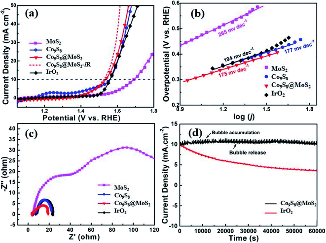
In 1 M KOH, the electrocatalytic performance of Co9S8@MoS2 for the OER was assessed. The individual Co9S8 and MoS2 materials were also examined for comparison. In addition, as a well-known OER catalyst, IrO2 was used as a benchmark. Fig. 4a illustrates representative polarisation curves for the various catalysts. The OER evaluation results of the catalyst decrease in the following order Co9S8@MoS2-iR > Co9S8@MoS2 > Co9S8 > IrO2 > MoS2. The potential required by Co9S8@MoS2 (1.525 V) to achieve at 10 mA cm−2 is found to be lower than those required by IrO2 (1.558 V), Co9S8 (1.558 V), and MoS2 (1.692 V). Based on the Tafel slopes derived from the linear sweep voltammetry curves (Fig. 4b), Co9S8@MoS2 exhibits the fastest kinetics for oxygen production. The Tafel slope for Co9S8@MoS2 (175 mV dec−1) is lower than those of Co9S8 (177 mV dec−1), MoS2 (265 mV dec−1), and even IrO2 (194 mV dec−1). In the Nyquist plots (Fig. 4c), a semicircle appears at high frequencies corresponding to the charge-transfer resistance. The diameter of this semicircle is smaller for Co9S8@MoS2 than for Co9S8, MoS2, and IrO2, indicating a lower charge-transfer resistance of the composite material.42 It is worth mentioning that, the in situ generated CoOOH of cobalt-based catalyst, which certainly include Co9S8@MoS2 and Co9S8,17,43 is generally claimed to be the actual active center for OER electrocatalysis.44–47 In our study, the exposable density of active sites and charge-transfer resistance of the transformed CoOOH-containing catalyst are mainly determining the OER electrocatalytic activity, not involving the dominated high intrinsic activity tuned by defect engineering and heteroatomic doping.44,48 Consequently, due to the nanostructural virtues of 3D porous framework and heterojunctions, the CoOOH-containing catalyst transformed from Co9S8@MoS2 shows the low charge-transfer resistance and high exposed active site, resulting in slightly enhanced OER activity. These results also founded by the previous reported literatures.3,17,40
Durability and stability are also key parameters for estimating the electrocatalytic capability of Co9S8@MoS2. The chronoamperometric responses (i–t) of catalysts were recorded at an applied potential of 1.558 V (vs. RHE). As demonstrated in Fig. 4d, the decrease in the current density of Co9S8@MoS2 over 15 h is insignificant than that of IrO2, showing the robust durability of Co9S8@MoS2. To further understand the stability of the Co9S8@MoS2, the SEM technique was performed after the OER test. As shown in the Fig. S3†, after the above long-time OER test, Co9S8@MoS2 can largely retained its original morphology, although a slight aggregation and surface collapse is observed, indicative of its excellent structural stability. The excellent stability of Co9S8@MoS2 can be ascribed to its unique heterostructures: (i) the interfacial interaction between Co9S8 and MoS2 enhances the density of electron transfer at the joint boundaries; (ii) a unique core–shell nanostructure is constructed by the highly active Co9S8 core, along with a more stable MoS2 shell; (iii) the 3D flower-like porous framework enables the easy release of bubbles formed on the surface of the electrode during operation, thus preventing the electrocatalyst from being removed from the electrode.
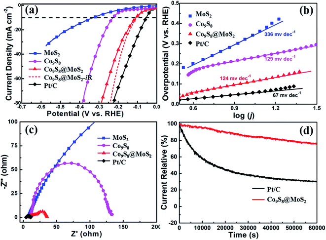
Similarly, the HER performance of Co9S8, MoS2, and Co9S8@MoS2 was assessed in 1 M KOH; a 20% Pt/C was also tested for comparison. Fig. 5a exhibits the polarisation curves of Co9S8, MoS2, Co9S8@MoS2, iR-corrected Co9S8@MoS2, and Pt/C obtained at a scan rate of 10 mV s−1 in 1 M KOH. Notably, the Pt/C exhibits superior HER activity, which merely need an overpotential of 54 mV at 10 mA cm−2. While the HER activity of Co9S8@MoS2 is weaker than that of Pt/C, it exhibits a lower overpotential (η10 = 103 mV) than MoS2 (η10 = 323 mV) and Co9S8 (η10 = 228 mV). The Tafel slopes (Fig. 5b) are estimated to be 336, 129, 124, and 67 mV dec−1 for MoS2, Co9S8, Co9S8@MoS2, and Pt/C. As shown by the Nyquist plots in Fig. 5c, the charge-transfer resistance of Co9S8@MoS2 is evidently lower than those of MoS2 and Co9S8, which is favourable for the HER. This remarkable enhanced HER activity for Co9S8@MoS2 is mainly due to its porous three-dimensional flower-like heterostructure spheres and the interfacial areas triggering electron transfer that can significantly increase the exposal of active sites and activates HER electrocatalysis.3,23,31 Moreover, the chronoamperometric curve in Fig. 5d exhibits that Co9S8@MoS2 is stable for more than 16 h and its microflower-like morphology can unambiguously observed in the SEM images taken after continuously catalyzing HER (Fig. S4†). In addition, in an acidic medium, the Co9S8@MoS2 electrode also exhibits remarkable HER activity, requiring a low potential of 114 mV at 10 mA cm−2 (Fig. S5†).
To determine the origin of the remarkable HER property of Co9S8@MoS2 in an alkaline solution, the electrochemically active surface areas (ECSAs) of the catalysts are considered. The electrochemical double-layer capacitance (Cdl) is positively correlated with the electrochemical surface area,14,49 therefore, the ECSA of each catalyst is estimated from the Cdl value, as calculated using the cyclic voltammetry curves obtained at a series of scan rates (20 to 100 mV s−1) in the non-faradaic reaction range. As observed in Fig. S6†, the Cdl value of Co9S8 (27.4 mF cm−2) and MoS2 (1.8 mF cm−2) is lower than that of Co9S8@MoS2 (40.0 mF cm−2) in 1 M KOH. Thus, it is observed that Co9S8@MoS2 exhibits outstanding electrocatalytic performance.
To further explicitly explain the effect of MoS2 concentration toward electrocatalytic HER and OER performance, two counterparts Co9S8@MoS2 with varying MoS2 concentration were prepared by feeding the different amount of Molybdenum salt and denoted as Co9S8@MoS2-low and Co9S8@MoS2-high. The electrochemical activities of Co9S8@MoS2 with different MoS2 concentration were investigated in alkaline media for OER and HER. As shown in Fig. S7†, Co9S8@MoS2-low exhibits the worst performances for both OER and HER may owing to its thin MoS2 nanosheets or less active sites on the interfaces of Co9S8 and MoS2. Although Co9S8@MoS2-high demonstrates a favorable improved the activities for both OER and HER compared to those exhibited by Co9S8@MoS2-low, it still displays the lower catalytic activities as compared with that of Co9S8@MoS2. This can be due to excessive MoS2 is coated on the surface of Co9S8, which obstruct the activity of the inner Co9S8 layer.38 Thus, Co9S8@MoS2 heterostructure with an optimal concentration of MoS2 were studied systematically in present work.
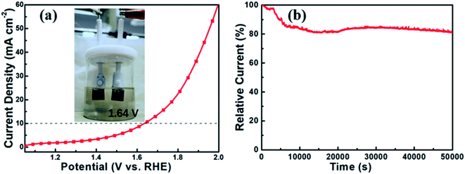
The above findings indicate that Co9S8@MoS2 is a satisfactory electrocatalyst for both the OER and the HER. In a two-electrode setup, Co9S8@MoS2 was used as both the anode and the cathode, and its catalytic performance for water splitting was assessed in 1 M KOH. In Fig. 6a, the Co9S8@MoS2 electrode exhibits excellent performance, attaining water splitting at 10 mA cm−2 under a low voltage of 1.64 V. Moreover, the long-term stability over 12 h was measured using chronoamperometry (Fig. 6b). The current density degraded only slightly, indicating the noteworthy stability of the Co9S8@MoS2 electrode for the water splitting reaction.
Thus, the flower-like Co9S8@MoS2 heterostructure obtained in this study possesses unique structural merits such as a hierarchical 3D porous framework and a 2D sheet-like heterojunction structure, which facilitate short diffusion channels and well-exposed active sites, showing a high electrochemical active area and low electrochemical impedance. These features afford remarkable bifunctional electrocatalytic performance and stability for the HER and OER, which compares favourably to contemporary nonprecious metal or leading cobalt- and molybdenum-based electrocatalysts (Table S1†).
Conclusions
A Co9S8@MoS2 bifunctional catalyst was designed and synthesised using a two-step process that combined a hydrothermal reaction and thermal annealing. During this process, surface coverage by MoS2 nanosheets hindered the formation of spherical Co9S8 particles, and the obtained porous structure was advantageous for electrolyte infiltration and the transportation of intermediates. The flower-like Co9S8@MoS2 heterostructure incorporated MoS2 as a stable HER catalyst of MoS2 and Co9S8 as a notable OER catalyst. Thus, Co9S8@MoS2 acted as a bifunctional catalyst with a low charge-transfer resistance and a high ECSA. Co9S8@MoS2 exhibited low overpotentials of 103 and 114 mV for the HER at 10 mA cm−2 under alkaline and acidic conditions, respectively. Moreover, the OER performance of Co9S8@MoS2 was satisfactory, and an overpotential of only 295 mV was required at 10 mA cm−2. Moreover, for water splitting, a low voltage of 1.64 V was achieved by employing the microflower-like Co9S8@MoS2 electrocatalyst as a two-electrode setup. The findings of this study provide insights for fabricating high-performance bifunctional electrocatalysts with advantageous structures for overall water splitting.Author contributions
Chaohai Pang: conceived and designed the experiments. Chaohai Pang and Xiaojing Zhu: Performed the experiments. Chaohai Pang and Xionghui Ma: Analyzed the data. Chaohai Pang: writing – original draft. Xiaojing Zhu, Yuwei Wu and Shuhuai Li: writing – review & editing. Zhi Xu and Mingyue Wang: supervision, funding acquisition and project administration. All authors have discussed and given approval to the final version of the manuscript.Conflicts of interest
There are no conflicts to declare.Acknowledgements
This work was financially supported by the Central Public-interest Scientific Institution Basal Research Fund for the Chinese Academy of Tropical Agricultural Sciences (Grant no.1251632022005). China Agriculture Research System of MOF and MARA (CARS-31). Key Laboratory of Tropical Fruits and Vegetables Quality and Safety for State Market Regulation (Grant no. ZX-2022002). Additional support was provided by the Foundation from Chemistry and Chemical Engineering Guangdong Laboratory (Grant no. 20111016) and the Basic and Applied Basic Research Foundation of Guangdong Province (Grant no. 2021A1515110111).References
- S. Chu and A. Majumdar, Nature, 2012, 488, 294–303 CrossRef CAS PubMed.
- X. Zou and Y. Zhang, Chem. Soc. Rev., 2015, 44, 5148–5180 RSC.
- Y. Li, C. Wang, M. Cui, J. Xiong, L. Mi and S. Chen, Appl. Surf. Sci., 2021, 543, 148804 CrossRef CAS.
- J. Greeley, T. F. Jaramillo, J. Bonde, I. Chorkendorff and J. K. Nørskov, Nat. Mater., 2006, 5, 909–913 CrossRef CAS PubMed.
- S. Cherevko, S. Geiger, O. Kasian, N. Kulyk, J. P. Grote, A. Savan, B. R. Shrestha, S. Merzlikin, B. Breitbath, A. Ludwig and K. J. J. Mayrhofer, Catal. Today, 2016, 262, 170–180 CrossRef CAS.
- K. Zhu, F. Shi, X. Zhu and W. Wang, Nano Energy, 2020, 73, 104761 CrossRef CAS.
- E. Willinger, C. Massué, R. Schlgl and M. G. Willinger, J. Am. Chem. Soc., 2017, 139, 12093–12101 CrossRef CAS PubMed.
- Y. Li, H. Huang, S. Chen, X. Yu, C. Wang and T. Ma, Nano Res., 2019, 12, 2774–2780 CrossRef CAS.
- M. Yang, J. Wang, H. Wu and G. W. Ho, Small, 2018, 14, 1703323 CrossRef PubMed.
- Y. Li, M. Cui, C. Wang, Y. Chen, S. Chen, L. Gao, A. Liu, W. Su and T. Ma, Mater. Today. Energy, 2020, 17, 100455 CrossRef.
- R. K. Kunchala, R. K. Pushpendra and B. S. Naidu, Sustainable Energy Fuels, 2022, 6, 766–777 RSC.
- R. K. Kunchala, R. K. Pushpendra and B. S. Naidu, ACS Appl. Nano Mater., 2021, 4, 396–405 CrossRef CAS.
- J. Xie, J. Zhang, S. Li, F. B. Grote, X. Zhang, H. Zhang, R. Wang, Y. Lei, B. Pan and Y. Xie, J. Am. Chem. Soc., 2013, 135, 17881–17888 CrossRef CAS PubMed.
- M. A. Lukowski, A. S. Daniel, F. Meng, A. Forticaux, L. Li and S. Jin, J. Am. Chem. Soc., 2013, 135, 10274–10277 CrossRef CAS PubMed.
- G. Zhang, H. Liu, J. Qu and J. Li, Energy Environ. Sci., 2016, 9, 1190–1209 RSC.
- E. E. Benson, H. Y. Zhang, S. A. Schuman, S. U. Nanayakkara, N. D. Bronstein, S. Ferrere, J. L. Blackburn and E. M. Miller, J. Am. Chem. Soc., 2017, 140, 441–450 CrossRef PubMed.
- J. Bai, T. Meng, D. Guo, S. Wang, B. Mao and M. Cao, ACS Appl. Mater. Interfaces, 2018, 10, 1678–1689 CrossRef CAS PubMed.
- H. Li, X. Qian, C. Xu, S. Huang, C. Zhu, X. Jiang, L. Shao and L. Hou, ACS Appl. Mater. Interfaces, 2017, 9, 28394–28405 CrossRef CAS PubMed.
- X. Xin, Y. Song, S. Guo, Y. Zhang, B. Wang, Y. Wang and X. Li, J. Alloys Compd., 2020, 829, 154635 CrossRef CAS.
- Y. Liu, C. Xiao, M. Lyu, Y. Lin, W. Cai, P. Huang, W. Tong, Y. Zou and Y. Xie, Angew. Chem., 2015, 127, 11383–11387 CrossRef.
- H. Wang, Z. Li, G. Li, F. Peng and H. Yu, Catal. Today, 2015, 245, 74–78 CrossRef CAS.
- S. Dou, L. Tao, J. Huo, S. Wang and L. Dai, Energy Environ. Sci., 2016, 9, 1320–1326 RSC.
- Y. Yang, H. Yao, Z. Yu, S. M. lslam, H. He, M. Yuan, Y. Yue, K. Xu, W. Hao, G. Sun, H. Li, S. Ma, P. Zapol and M. G. Kanatzidis, J. Am. Chem. Soc., 2019, 141, 10417–10430 CrossRef CAS PubMed.
- Y. Xi, N. Angulakshmi, B. Zhang, X. Tian, Z. Tang, P. Xie, G. Chen and Y. Zhou, J. Alloys Compd., 2020, 826, 154201 CrossRef CAS.
- U. Maitra, B. S. Naidu, A. Govindaraj and C. N. R. Rao, PNAS, 2013, 110, 11704–11707 CrossRef CAS PubMed.
- U. Gupta, B. S. Naidu and C. N. R. Rao, Dalton Trans., 2015, 44, 472–474 RSC.
- B. S. Naidu, U. Gupta, U. Maitra and C. N. R. Rao, Chem. Phys. Lett., 2014, 591, 277–281 CrossRef CAS.
- X. Yu, Y. Feng, Y. Jeon, B. Guan, X. Lou and U. Paik, Adv. Mater., 2016, 28, 9006–9011 CrossRef CAS PubMed.
- W. Zhang, L. Cui and J. Liu, J. Alloys Compd., 2020, 821, 153542 CrossRef CAS.
- J. Dai, D. Zhao, W. Sun, X. Zhu, L. Ma, Z. Wu, C. Yang, Z. Cui, L. Li and S. W. Chen, ACS Catal., 2019, 9, 10761–10772 CrossRef CAS.
- L. Diao, B. Zhang, Q. Sun, N. Wang, N. Zhao, C. Shi, E. Liu and C. He, Nanoscale, 2019, 11, 21479–21486 RSC.
- B. Li, Q. Su, L. Yu, J. Zhang, G. Du, D. Wang, D. Han, M. Zhao, S. Ding and B. Xu, ACS Nano, 2020, 14, 17285–17294 CrossRef CAS PubMed.
- M. Wang, K. Jian, Z. P. Lv, D. Li, G. Fan, R. Zhang and J. Dang, J. Mater. Sci. Technol., 2020, 79, 29–34 CrossRef.
- J. Wu, X. Wang, J. Jiang, W. Lin, S. Zhu, J. Sha, L. Ma and N. Zhao, Mater. Lett., 2021, 292, 129621 CrossRef CAS.
- N. Huang, S. Yan, M. Zhang, Y. Ding, L. Yang, P. Sun and X. Sun, Electrochim. Acta, 2019, 327, 134942 CrossRef CAS.
- L. He, S. Huang, Y. Liu, M. Wang, B. Cui, S. Wu, J. Liu, Z. Zhang and M. Du, J. Colloid Interface Sci., 2021, 586, 538–550 CrossRef CAS PubMed.
- X. Zhu, Q. Wu, J. Dai, D. Zhao, C. Yang, L. Li, N. Li and S. Chen, Electrochim. Acta, 2021, 384, 138299 CrossRef CAS.
- Y. Guo, J. Tang, H. Qian, Z. Wang and Y. Yamauchi, Chem. Mater., 2017, 29, 5566–5573 CrossRef CAS.
- F. Du, L. Shi, Y. Zhang, T. Li, J. Wang, G. Wen, A. Alsaedi, T. Hayat, Y. Zhou and Z. Zou, Appl. Catal., B, 2019, 253, 246–252 CrossRef CAS.
- Y. Guo, J. Tang, Z. Wang, Y. Kang, Y. Bando and Y. Yamauchi, Nano Energy, 2018, 47, 494–502 CrossRef CAS.
- X. Yang, H. Sun, P. Zan, L. Zhao and J. Lian, J. Mater. Chem. A, 2016, 4, 18857–18867 RSC.
- M. Zheng, J. Du, B. Hou and C. Xu, ACS Appl. Mater. Interfaces, 2017, 9, 26066–26076 CrossRef CAS PubMed.
- M. Bajdich, M. Garcia-Mota, A. Vojvodic, J. K. Norskov and A. T. Bell, J. Am. Chem. Soc., 2013, 135, 13521–13530 CrossRef CAS PubMed.
- S. Chakrabartty, S. Karmakar and C. R. Raj, ACS Appl. Nano Mater., 2020, 3, 11326–11334 CrossRef CAS.
- W. Chen, Y. Liu, Y. Li, J. Sun, Y. Qiu, C. Liu, G. Zhou and Y. Cui, Nano Lett., 2016, 16, 7588–7596 CrossRef CAS PubMed.
- K. Fan, H. Zou, Y. Lu, H. Chen, F. Li, J. Liu, L. Sun, L. Tong, M. F. Toney, M. Sui and J. Yu, ACS Nano, 2018, 12, 12369–12379 CrossRef CAS PubMed.
- W. Li, D. Xiong, X. Gao and L. Liu, Chem. Commun., 2019, 55, 8744–8763 RSC.
- G. Huang, Z. Xiao, R. Chen and S. Wang, ACS Sustainable Chem. Eng., 2018, 6, 15954–15969 CrossRef CAS.
- L. Yu, B. Xia, X. Wang and X. Lou, Adv. Mater., 2016, 28, 92–97 CrossRef CAS PubMed.
Footnotes |
| † Electronic supplementary information (ESI) available. See https://doi.org/10.1039/d2ra04086g |
| ‡ C. P and X. M contributed equally to this work. |
| This journal is © The Royal Society of Chemistry 2022 |

