
 Open Access Article
 This Open Access Article is licensed under a Creative Commons Attribution-Non Commercial 3.0 Unported Licence
MWCNT modified Ni–Fe LDH/BiVO4 heterojunction: boosted visible-light-driven photoelectrochemical aptasensor for ofloxacin detection†
Xuejun Qi * and
Shuyan Tao
* and
Shuyan Tao
School of Architecture and Civil Engineering, Xihua University, Chengdu 610039, PR China. E-mail: xuejunqi@hotmail.com
First published on 26th August 2022
Abstract
Sensitivity and selectivity, which can be identified by the photosensitivity of materials and the identification of elements, are two important factors for a photoelectrochemical aptasensor (PEC aptasensor). Herein, a patent PEC aptasensor for specifically detecting ofloxacin (OFL) was exploited, and a visible-light-active MWCNT/LDH/BiVO4 heterostructure was introduced as a photoactive material and identification elements, respectively. The combination of LDH with BiVO4 enhanced the photocurrent response, and MWCNT provided higher electron conductivity, which are advantageous for structuring PEC sensors. Furthermore, the two-pot synthesis of MWCNT/LDH/BiVO4 has the advantage of possessing an environmentally friendly character. Under optimal conditions, the photocurrent response of MWCNT/LDH/BiVO4 presents a linear trend with OFL concentration from 0.1 to 16![[thin space (1/6-em)]](https://www.rsc.org/images/entities/char_2009.gif) 000 nM, and the limit of detection (S/N = 3) is as low as 0.03 nM. This new PEC sensing device afforded an ultra-sensitive sensor which has high selectivity and stability for detecting OFL.
000 nM, and the limit of detection (S/N = 3) is as low as 0.03 nM. This new PEC sensing device afforded an ultra-sensitive sensor which has high selectivity and stability for detecting OFL.
1. Introduction
Ofloxacin (OFL) is a kind of pharmaceutical compound highly consumed by human beings for treating skin tissue and bacterial infections.1,2 Pharmaceutical compounds inherently exist in waste water, which has drawn people's attention because a lower concentration of pharmaceutical compounds can also cause problems if they are disposed of improperly.3,4 Moreover, OFL has been widely applied only in waste water systems as it is toxic to aquatic systems and ecosystems.5,6 Therefore, there is an urgent need for OFL detection.Actually, OFL can be detected by many technologies which have been proposed over the years, such as mass spectrometry, liquid chromatography tandem mass spectrometry, surface-enhanced Raman scattering, fluorescence spectroscopy, electrochemistry, and photoelectrochemistry.7–11 Photoelectrochemistry (PEC) is a newly exploited system for detection, which takes advantage of light and electricity to excite the sensor and detect the target, respectively, hence efficiently reducing some unacceptable background noise and improving the sensitivity.12–15
Currently, bismuth-based photocatalysis materials cannot be ignored owing to their band structures being radically distinctive and their photocorrosion stability being higher than others.16,17 Among them, BiVO4 is one of the most attractive materials for researchers because it has a narrow band-gap energy (2.45 eV) with a high level of photocatalytic activity under visible-light irradiation.18 However, because of the comparatively quick recombination of photogenerated electron–hole pairs, the photoactivity of BiVO4 alone is definitely inferior.19 So to resolve these problems, many strategies like metal deposition and semiconductor compounds have been put forward to improve the PEC activity of BiVO4.20 In particular, composite photocatalysts based on both BiVO4 and a noble metal show better photocatalytic activity than bare BiVO4. The reason is that the noble metal has the ability to increase the separation efficiency of photogenerated carriers and the transfer efficiency of interfacial charge.21,22
Multi-walled carbon nanotubes (MWCNTs) attract many people because of their unique structure and electrical properties.23,24 It is noteworthy that the incorporation of MWCNTs over a semiconducting photoanode demonstrated significant absorption of visible light, high mechanical and chemical stability and enhanced charge transport due to their having higher conductivity than semiconductors. What is more, MWCNTs possess greater electronic conductivity. They work like an effective electron acceptor to accelerate photo-induced charge transfer, which increases the PEC performance.25,26 LDH-based materials which can be used for photocatalytic applications have been known to researchers because of their prominent efficiency for redox reactions.27 Besides, they are non-toxic and could also be provided simply. The new composition of LDH compounds could doubtless have an influence on photocatalytic reactions. Their tunable layers like brucite and their unsaturated metal cations (M2+ and M3+) are nicely dispersed. Both of them can form oxo-bridged links with octahedrally coordinated hydroxide ions for arrangement in an octahedral orientation.28 Then, because of the constitution of oxo-bridges, the metal-to-metal charge could transfer smoothly, which in turn is a critical element for visible-light redox reactions by reducing the speed of electron–hole recombination.29,30
In this recent study, a sensing platform was formed based on MWCNT/LDH/BiVO4. Moreover, the photocurrent of the MWCNT/LDH/BiVO4 structure was enhanced by the effects of MWCNT and LDH. In OFL detection, it is easy to obtain a wide linear range under a considerably low detection limit. This study shows that the PEC sensor has significant ability to detect OFL in a blood sample or a complex sample due to its great anti-interference performance.
2. Experimental
This section is to be found in the ESI.†3. Results and discussion
3.1. Choice of materials
The powder X-ray diffraction patterns of pristine BiVO4, LDH/BV-X% (LDH/BiVO4-X%) and Y-M/LDH/BV-5% (Y-MWCNT/LDH/BiVO4-5%) were registered and are displayed in Fig. 1. Pristine BiVO4 exposes a phase of an orthorhombic crystal which is well-matched with JCPDS card no. 75-1867. Diffraction peaks located at diffraction angles of 18.98°, 28.83°, 30.53° and 47.31° corresponding to the (110), (121), (040) and (042) planes were observed. The high purity of the synthesized BiVO4 can be verified by the lack of any other peaks. In the XRD patterns of LDH/BV-X%, the characteristic diffraction peaks of NiFe–LDH (JCPDS no. 40-0215) can be found in the (003) and (006) peaks which appeared in the XRD pattern (Fig. S1†). Moreover, the featured peak of Y-M/LDH/BV-5% separately appearing at approximately 26.01° accords with the (002) plane of MWCNT. And this phenomenon proves the successful electrode position of MWCNT and NiFe–LDH on the surface of BiVO4. | ||
| Fig. 1 XRD patterns of all materials. | ||
As shown in Fig. S2A,† the photocurrent responses of BiVO4, LDH/BV-X% and Y-M/LDH/BV-5% were measured in 0.1 M PBS. Under visible-light irradiation, the LDH/BV-5% photoelectrode shows a higher photocurrent than BiVO4, LDH/BV-2% or LDH/BV-7%. The photocurrent increases significantly after the introduction of MWCNT, and 20-M/LDH/BV-5% has higher photocurrent than 10-M/LDH/BV-5% or 30-M/LDH/BV-5%. The electrode kinetics and the charge transfer on the material surface are frequently studied by the method of EIS analysis. And this method has been demonstrated to be a kind of valid characterization of the transfer rate of electrons in PEC materials. The results of the EIS analysis can be found in Fig. S2B.† As everyone knows, electrons could be transmitted with a higher rate in an EIS curve with a smaller radius of curvature. And 20-M/LDH/BV-5% shows a significantly smaller radius of curvature than BiVO4, LDH/BV-X% or Y-M/LDH/BV-5%. This might be the result of the introduction of MWCNT and NiFe–LDH, the elements with the fastest electron transport rate and most enhanced PEC performance. Based on the above results, 20-M/LDH/BV-5% was selected for further investigation.
3.2. Characterization of the 20-M/LDH/BV-5% heterojunction
The surface composition and chemical state of 20-M/LDH/BV-5% were studied and analysed by the method of XPS. The C 1s XPS is illustrated in Fig. 2A. The four peaks standing at 284.12 eV, 284.6 eV, 285.69 eV and 288.48 eV can be put down to C–O, C–C![[double bond, length as m-dash]](https://www.rsc.org/images/entities/char_e001.gif) C, CO and O–CO, respectively.31 It is easy to find from Fig. 2B that two peaks can be seen at about 164.5 and 159.3 eV in the Bi spectrum,32 and they belong to two different parts of the spectrum, Bi 4f7/2 and Bi 4f5/2, respectively, of Bi3+. In the V spectrum it can be observed that there are two peaks at 516.1 and 524.5 eV, consistent with V 2p3/2 and V 2p1/2 of the V5+ species of BiVO4 (Fig. 2C).33 The peaks standing at 855.6 and 873.7 eV can be ascribed to the Ni 2p3/2 and Ni 2p1/2 of Ni2+ (Fig. 2D).34 And the peaks standing at 878.9 and 861.7 eV are a kind of satellite peak. For Fe 2p species (Fig. 2E), the peaks standing at 712.4 and 724.6 eV should be ascribed to the Fe 2p3/2 and Fe 2p1/2 of Fe3+.35 Three constituent peaks can be formed by deconvoluting the O 1s peak into 530.1 eV, 531.0 eV, and 531.9 eV (Fig. 2F), and these peaks correspond to the lattice oxygen (Bi–O–Bi) of BiVO4, adsorbed oxygen on the surface of BiVO4 and surface-adsorbed water or the hydroxyl group.36 Therefore, the XPS results confirm that 20-M/LDH/BV-5% had been fabricated.
C, CO and O–CO, respectively.31 It is easy to find from Fig. 2B that two peaks can be seen at about 164.5 and 159.3 eV in the Bi spectrum,32 and they belong to two different parts of the spectrum, Bi 4f7/2 and Bi 4f5/2, respectively, of Bi3+. In the V spectrum it can be observed that there are two peaks at 516.1 and 524.5 eV, consistent with V 2p3/2 and V 2p1/2 of the V5+ species of BiVO4 (Fig. 2C).33 The peaks standing at 855.6 and 873.7 eV can be ascribed to the Ni 2p3/2 and Ni 2p1/2 of Ni2+ (Fig. 2D).34 And the peaks standing at 878.9 and 861.7 eV are a kind of satellite peak. For Fe 2p species (Fig. 2E), the peaks standing at 712.4 and 724.6 eV should be ascribed to the Fe 2p3/2 and Fe 2p1/2 of Fe3+.35 Three constituent peaks can be formed by deconvoluting the O 1s peak into 530.1 eV, 531.0 eV, and 531.9 eV (Fig. 2F), and these peaks correspond to the lattice oxygen (Bi–O–Bi) of BiVO4, adsorbed oxygen on the surface of BiVO4 and surface-adsorbed water or the hydroxyl group.36 Therefore, the XPS results confirm that 20-M/LDH/BV-5% had been fabricated.
 | ||
| Fig. 2 XPS of C 1s (A), Bi 4f (B), V 2p (C), Ni 2p (D), Fe 2p (E) and O 1s (F). | ||
The morphology of the 20-M/LDH/BV-5% heterostructure was examined by SEM. As-prepared 20-M/LDH/BV-5% showed that MWCNTs are attached to the structure, which looks like sheet (Fig. 3A and B). With the help of TEM, people can obtain the interspersion state of these nanoparticles and their added structural information. The HRTEM image confirmed this unique morphology and further indicated that the compound was composed of MWCNT, BiVO4 and Ni–Fe LDH.
 | ||
| Fig. 3 (A) SEM image, (B and C) TEM image and (D) HRTEM image of 20-M/LDH/BV-5%. | ||
The optical properties of BiVO4, LDH/BV-5% and 20-M/LDH/BV-5% were researched with the help of UV-visible diffuse reflectance spectroscopy. As is conveyed by Fig. 4A, significant absorption could be seen from the BiVO4 nanoparticles at wavelengths below 400 nm due to the band gap being particularly large. And the visible range of 200–700 nm is the best absorption region of LDH/BV-5%. The absorption ability of 20-M/LDH/BV-5% increased after the addition of MWCNT and LDH, which shows that MWCNT and LDH can improve visible-light utilization.37 After that, the capacity of the synthesized materials which can separate electrons and holes was further researched with photoluminescence (PL) spectra. Fig. 4B also displays the lower intensity of 20-M/LDH/BV-5% than BiVO4 or LDH/BV-5%, suggesting that 20-M/LDH/BV-5% has a low electron recombination rate.38 According to the above discussion, 20-M/LDH/BV-5% presents excellent PEC performance.
 | ||
| Fig. 4 UV-vis diffuse reflectance spectra (A) and PL spectra (B) of BiVO4, LDH/BV-5% and 20-M/LDH/BV-5%. | ||
3.3. Theoretical calculations
DFT determined the density of states (DOS) and energy band structures for BiVO4 and 20-M/LDH/BV-5% (Fig. 5). Clearly, BiVO4 can serve as the photocatalytic material of an indirect band-gap semiconductor since the valence band maximum (VBM) and conduction band minimum (CBM) are located at diverse points of high symmetry, as seen between the CBM at the Γ-point and the VBM at the X-point. Calculations yielded a BiVO4 band gap of 2.31 eV. Notably, the band gaps were significantly lower than in experimental measurements (2.45 eV for BiVO4), likely due to a defective GGA function (Fig. 5A and B). To determine the role of 20-M/LDH/BV-5% as an excellent co-catalyst for improving BiVO4 photocatalytic activity, we used the Vienna Ab Initio Simulation Package (VASP) for density functional theory (DFT) calculations. And likely due to a defective GGA function (Fig. 5C and D). In the photocatalyst, photogenerated h+ and e− were efficiently isolated and quickly transported onto surfaces. Fig. 5C and D show the DOS with 20-M/LDH/BV-5%, which indicated that MWCNT and LDH gain charges as electron trapping and shuttling sites, suppressing the recombination of electrons/holes, and promoting electron separation and transfer.39 | ||
| Fig. 5 Band structures for (A) BiVO4 and (B) 20-M/LDH/BV-5%; DOS for (C) BiVO4 and (D) 20-M/LDH/BV-5%. | ||
3.4. Characterization of PEC aptasensor
To some degree, the transient photocurrent response has the effect of reflecting the PEC performance of the material. In Fig. 6, the instantaneous PEC response curves of BiVO4, 20-M/LDH/BiVO4-5%, aptamer/20-M/LDH/BV-5%, MCH/aptamer/20-M/LDH/BV-5% and OFL/MCH/aptamer/20-M/LDH/BV-5% were tested by intermittent light irradiation at intervals of 20 s in 0.1 M PBS solution containing 0.1 M AA with a bias condition of 0.1 V. The photocurrent intensity of BiVO4 exposed to light was quickly enhanced. The photocurrent could remain at a relatively stable level, although the illumination time was rising. And the photocurrent density would reduce at once without light, because the photoinduced carriers recombined quickly. Comparing the transient photocurrent response curves of BiVO4, the increase in the photocurrent of 20-M/LDH/BiVO4-5% was found to be more significant than that of BiVO4. 20-M/LDH/BiVO4-5% displayed the maximum photocurrent density. A possible mechanism for the increasing photocurrent of 20-M/LDH/BiVO4-5% is proposed (Scheme 1B): under illumination, the electrons will be transferred through the path NiFe–LDH → BiVO4 → MWCNT → ITO. At the same time, NiFe–LDH as a hole collector has the ability to more effectively use the photogenerated holes which accumulate in the valence band of NiFe–LDH to oxidize AA. Moreover, garnishing with MWCNT forms a bridge between the electrode and BiVO4 which leads to the formation of a conducting channel and provides a network which is favorable for charge collection and transport. AA, a high-efficiency electron donor, can curb the recombination of e−/h+, thereby promoting stable generation of the photocurrent signals; thus charge separation can be promoted and electronic transfer can be efficiently enhanced, also resulting in an enhanced photocurrent.35,37 | ||
| Fig. 6 Photocurrent responses for (a) BiVO4, (b) 20-M/LDH/BV-5%, (c) aptamer/20-M/LDH/BV-5%, (d) MCH/aptamer/20-M/LDH/BV-5%, (e) OFL/MCH/aptamer/20-M/LDH/BV-5% in PBS with 0.1 M AA at 0.1 V vs. SCE. | ||
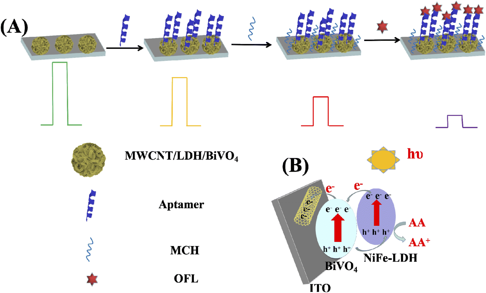 | ||
| Scheme 1 (A) Fabrication steps of a ofloxacin aptasensor and (B) schematic illustration of the PEC aptasensor for detecting of ofloxacin. | ||
Then, the photocurrent presented an obvious decrease to 5.79 μA cm−1 as the aptamer was immobilized onto the electrode modified by 20-M/LDH/BiVO4-5% (curve c), due to the steric hindrance effect imposed by the immobilized aptamer together with the electrostatic repulsion effect between the electro-negative AA molecule and the aptamer's negatively charged phosphate skeleton. Then MCH successive blocking (curve d) contributed to a gradual decrease in the photocurrent since an increase in stereo-hindrance hindered the combination of AA and photogenerated holes as well as promoting recombination of photogenerated holes/electrons. Therefore, the connection of 50 nM of OFL to the aptamer through certain recognition led to an obvious reduction in the photocurrent value to 3.68 μA cm−1 (curve e), considering the specific binding of OFL to aptamers on 20-M/LDH/BiVO4-5%, and that the electrode surface is covered by the formed aptamer–OFL complex. The above-mentioned biomolecules exhibit steric hindrance at the interface of the electrode, preventing electrons from transferring to the surface of the electrode, thereby reducing the photocurrent (Scheme 1A).38–40 The above phenomena explained the successful construction of a PEC aptasensor based on 20-M/LDH/BiVO4-5% nanocomposites for detecting OFL.
3.5. Optimization of experimental conditions
To establish an environment with better detecting conditions, the impacts of the concentration of AA and its utilization potentiality were investigated using 20-M/LDH/BV-5%. The results can be seen in Fig. 7A. The photoelectrochemical responses of 20-M/LDH/BV-5% were examined in 0.1 M PBS solutions containing 0.01–0.2 M AA. According to Fig. 7B, the photocurrent signal intensity was boosted with an enhancement in the concentration of AA until the concentration of AA reached 0.1 M, after which it would increase slowly. As a result, 0.1 M AA would be the optimal condition for the experiment. A battery of photocurrent curves with a potential range which is suitable for application, from −0.1 V up to 0.2 V, under blue light is illustrated in Fig. 7B. When the applied potential is at 0.1 V, it is easy to obtain a first-class photocurrent response. Therefore, we chose the applied potential of 0.1 V as the optimal factor for the experiments.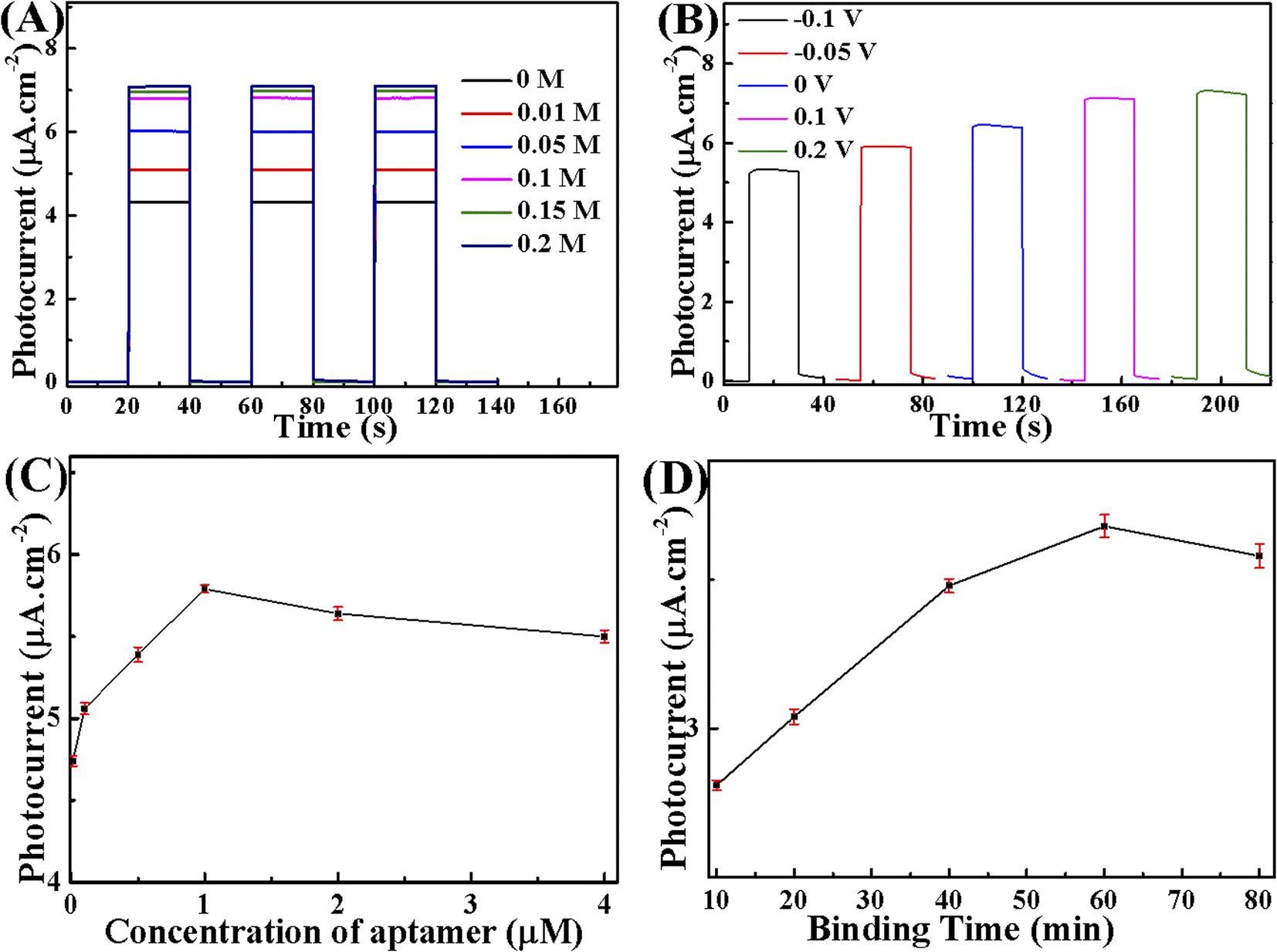 | ||
| Fig. 7 (A) Concentration of AA and (B) effect of applied potential on 20-M/LDH/BV-5%; (C) influences of aptamer concentration and (D) binding time of OFL with 0.1 M PBS solution containing 0.1 M AA at an applied potential of 0.1 V under visible-light irradiation. | ||
The concentration of aptamer is a vital factor influencing the sensitivity of a PEC aptasensor. To quantitatively evaluate the response of the aptasensor to OFL, the difference in photocurrent before and after incubation with OFL was calculated as the net PEC response. Fig. 7C displays the photocurrents of different concentrations of aptamer-modified electrode incubated with 50 nM OFL. There was a gradual increase in photocurrent with an increase in the aptamer concentration from 0.1 to 1.0 μM, indicating that a higher concentration of aptamer immobilized on the electrode surface could capture more OFL molecules. However, the photocurrent decreased slowly when the aptamer concentration exceeded 1.0 μM, which could be attributed to the increased steric hindrance generated by excessive aptamer that impeded the transfer of electrons. Therefore, 1.0 μM was chosen to be the optimized concentration of the aptamer for fabrication of the aptasensor.
The binding time of OFL with its aptamer is another important factor that affected the fabrication of the aptasensor. As displayed in Fig. 7D, the photocurrent of the aptasensor increased with an increase in binding time from 10 to 60 min and then reached a stationary plateau region at 60 min. Thus, 60 min at room temperature was selected as the optimal binding time between the sensing interfaces with OFL molecules in this research.
3.6. Analytical performance of the PEC aptasensor
The PEC potential of the prepared 20-M/LDH/BV-5% electrode to detect OFL was studied. The transient photocurrent responses of 20-M/LDH/BV-5% in the presence of 0.1 M PBS containing 0.1 M AA with continuous accretion of various molar concentrations of OFL (0.1 nM to 16000 nM) are shown in Fig. 8A. The OFL concentration increases from 0.1 nM to 16000 nM, suggesting that the incorporation of OFL could prevent the process of photoelectric conversion. And this phenomenon can decrease the photocurrent uniformly. As can be seen from Fig. 8B, the OFL concentration increases with growth in the photocurrent increment (I–Io). In this figure, the photocurrent intensity is described as I when OFL is present, and the photocurrent is described as Io when OFL is absent. Fig. 8B presents the linear regression of the logarithmic concentration of OFL versus the transformation of photocurrent, equivalent to ΔI = 0.625lgC + 0.6361 (C: OFL concentration, 0.1–16000 nM) with correlation coefficient R2 = 0.9969, which has an approximately 0.03 nM limit of detection. Table 1, shows the available technologies and their values in the literature. It is easy to observe that this sensor's detection limit was comparable to the methods which were put forward in other theses, but sometimes it could indeed be inferior to other methods. But this structured sensor was easy, quick and low-cost. So, the method discussed above could possibly be used for sensitivity measurement.
 | ||
| Fig. 8 (A) Photocurrent responses of MCH/aptamer/20-M/LDH/BV-5% with increasing concentrations of OFL. (B) Corresponding calibration plots of OFL concentration. (C) Stable photocurrent response curve with regard to the MCH/aptamer/20-M/LDH/BV-5% electrode toward 50 nM OFL. (D) Influence of interference on 50 nM OFL determination at 0.1 V vs. SCE under visible-light excitation. | ||
| Method | Linear range (M) | LOD (M) | Ref. |
|---|---|---|---|
| Electrochemical | 1.0 × 10⁻⁶ to 1.0 × 10⁻⁴ | 1.3 × 10⁻⁶ | 40 |
| Voltammetric | 1 × 10⁻⁸ to 1 × 10⁻⁶ | 8.0 × 10⁻⁹ | 41 |
| PEC aptasensor | 5.0 × 10⁻¹² to 1.0 × 10⁻⁷ | 7.5 × 10⁻¹³ | 42 |
| PEC aptasensor | 1.00 × 10⁻⁹ to 1.20 × 10⁻⁵ | 3.50 × 10⁻¹⁰ | 38 |
| PEC aptasensor | 1.00 × 10⁻¹⁰ to 1.60 × 10⁻⁵ | 3.0 × 10⁻¹¹ | This work |
The 50.0 nM OFL was detected five times to evaluate reproducibility by the same sensor. From the results of Fig. S2,† we can see that the PEC sensor shows great reproduction ability. In reality, the PEC sensor's stability was a significant element. Fig. 8C records the photocurrent responses every 20 s, when the excitation light was turned on and off each time. This process of irradiation could be repeated for more than 500 s. The result of the observation showed that the photocurrent density did not reveal any remarkable change, keeping a steady level, illustrating that the PEC sensor displayed prime stability under the condition of visible irradiation.
In order to appraise the selectivity of PEC sensor in OFL detection, the photocurrent was also compared against a range of universal chemical or biological interfering species with OFL and different metal ions, inspected under the same experimental conditions. The results demonstrate that the constructed PEC sensor has a barely distinguishable PEC response against these interfering agents with 100 times the concentration of OFL (Fig. 8D). This shows that the PEC sensor has perfect anti-interference ability to determine OFL.
3.7. Analytical application in real samples
To verify the application performance exhibited by the prepared 20-M/LDH/BV-5% in practice, human blood serum samples containing OFL were used as real samples for testing. Samples were obtained from ZiJing Hospital (Wuhan City, Hubei Province). Table 2 lists the results, with a relative standard deviation (RSD) value less than 2.33%, and a recovery of 99.70–100.11%. In summary, the results indicate that a sensor which is based on 20-M/LDH/BV-5% can be used for actual OFL detection.| Samples | Added (nM) | Found (nM) | Recovery (%) | RSD (%) | HPLC (nM) |
|---|---|---|---|---|---|
| Human serum | 10 | 9.97 | 99.70 | 1.19 | 9.98 |
| 50 | 49.91 | 99.82 | 2.21 | 49.95 | |
| 100 | 100.11 | 100.11 | 2.33 | 99.90 |
4. Conclusions
In this paper, we successfully instituted a visible-light-prompted PEC sensor based on MWCNT/NiFe–LDH/BiVO4, which could be used to detect OFL with regenerative and sensitive properties. MWCNT/NiFe–LDH/BiVO4 shows higher charge separation efficiency than BiVO4 to promote the activity of PEC. The introduction of OFL can effectively capture holes on the surface of the PEC sensor, leading to prominent enhancement of the photocurrent. In this respect, the MWCNT/NiFe–LDH/BiVO4-based PEC sensor shows remarkable performance for probing OFL with a low detection limit. In general, the durability, sensitivity and reusability of the PEC sensor reveal brilliant possibilities in real analysis.Conflicts of interest
There are no conflicts to declare.References
- Y. K. Huang, C. Wang, Q. M. Wei, Y. N. Song, P. F. Chen, L. J. Wang, X. Yang and X. G. Chen, Talanta, 2021, 235, 122783 CrossRef CAS PubMed.
- Y. Chen, L. Xu, J. T. Dong, P. C. Yan, F. Chen, J. C. Qian and H. N. Li, Electrochim. Acta, 2021, 368, 137595 CrossRef CAS.
- J. Wain, J. A. Simpson, L. T. D. Nga, T. S. Diep, P. T. Duy, S. Baker, N. P. J. Day, N. J. White and C. M. Parry, J. Antimicrob. Chemother., 2021, 76, 2606–2609 CrossRef CAS PubMed.
- Z. L. Du, K. J. Li, S. X. Zhou, X. Y. Liu, Y. Yu, Y. H. Zhang, Y. D. He and Y. J. Zhang, Chem. Eng. J., 2020, 380, 122427 CrossRef CAS.
- K. J. Li, A. L. Xu, D. H. Wu, S. Y. Zhao, T. Meng and Y. J. Zhang, Bioresour. Technol., 2021, 328, 124826 CrossRef CAS PubMed.
- Y. Xie, P. B. Wang, P. Li and Y. L. He, Bioresour. Technol., 2022, 350, 126938 CrossRef CAS PubMed.
- Y. Q. Wang, Z. Fang, H. Min, X. Y. Xu and Y. Li, ACS Appl. Nano Mater., 2022, 5(6), 8467–8474 CrossRef CAS.
- Z. N. Yu, L. Huang, Z. M. Zhang and G. K. Li, Anal. Chem., 2021, 93(38), 13072–13079 CrossRef CAS PubMed.
- O. Tadashi, S. Manabu, K. Masakiyo, U. Tsukasa and S. Kazunobu, Ther. Drug Monit., 1996, 18, 598–603 CrossRef PubMed.
- L. Feng, Q. Xue and F. Liu, Microchim. Acta, 2020, 187, 86 CrossRef CAS PubMed.
- T. T. Lin and Y. Shen, J. Electroanal. Chem., 2020, 870, 114247 CrossRef CAS.
- Y. Chen, L. Xu, M. Y. Yang, Y. F. Jia, Y. T. Yan, J. C. Qian, F. Chen and H. N. Li, Sens. Actuators, B, 2022, 353, 131187 CrossRef CAS.
- E. Samuel, B. Joshi, M. W. K. T. Swihart and S. S. Yoon, Nano Energy, 2020, 72, 104648 CrossRef CAS.
- J. J. Xi, H. Wang, B. H. Zhang, F. Q. Zhao and B. Z. Zeng, Sens. Actuators, B, 2020, 4, 128409 CrossRef.
- J. L. Li, Q. M. Wang, Y. J. Zhang, Y. Q. Liu, X. H. Liu and Z. B. Jiao, Solid State Sci., 2020, 104, 106200 CrossRef CAS.
- P. T. Sheng, L. Yao, P. Yang, D. F. Yang, C. K. Lu, K. S. Cao and W. L. Li, J. Alloys Compd., 2020, 822, 153700 CrossRef CAS.
- W. C. Fang, R. Tao, Z. B. Jin, Z. X. Sun, F. Y. Li and L. Xu, J. Alloys Compd., 2019, 797, 140–147 CrossRef CAS.
- Y. J. Pang, Y. W. Li, G. Q. Xu, Y. T. Hu, Z. K. Kou, Q. Feng, J. Lv, Y. Zhang, J. Wang and Y. C. Wu, Appl. Catal., B, 2019, 248, 255–263 CrossRef CAS.
- Y. L. Liu, H. M. Zeng, Y. Q. Chai, R. Yuan and H. Y. Liu, Chem. Commun., 2019, 55, 13729–13732 RSC.
- S. Y. Zhang, M. Rohloff, O. Kasian, A. M. Mingers, K. J. J. Mayrhofer, A. Fischer, C. Scheu and S. Cherevko, J. Phys. Chem. C, 2019, 123, 23410–23418 CrossRef CAS.
- S. Kumar, T. Malik, D. Sharma and A. K. Ganguli, ACS Appl. Nano Mater., 2019, 2, 2651–2662 CrossRef CAS.
- K. K. Dey, S. Gahlawata and P. P. Ingole, J. Mater. Chem. A, 2019, 7, 21207–21221 RSC.
- M. Rohloff, B. Anke, O. Kasian, S. Zhang, M. Lerch, C. Scheu and A. Fischer, ACS Appl. Mater. Interfaces, 2019, 11, 16430–16442 CrossRef CAS PubMed.
- S. S. Patil, M. AliJohar, M. AfifiHassan, D. R. Patil and S. W. Ryu, Appl. Catal., B, 2018, 237, 791–801 CrossRef CAS.
- M. L. Chang, L. P. Wu, X. J. Li and W. Xu, J. Mater. Sci. Technol., 2012, 28, 594–598 CrossRef CAS.
- S. Iguchi, S. Kikkawa, K. Teramura, S. Hosokawa and T. Tanaka, Phys. Chem. Chem. Phys., 2016, 18, 13811–13819 RSC.
- L. X. Sun, J. H. Sun, X. J. Yang, S. L. Bai, Y. J. Feng, R. X. Luo, D. Q. Li and A. F. Chen, Dalton Trans., 2019, 48, 16091–16098 RSC.
- A. E. A. Aboubakr, W. M. A. E. Rouby, M. D. Khan, A. A. Farghali and N. Revaprasadu, Appl. Surf. Sci., 2020, 508, 145100 CrossRef CAS.
- X. F. Zhao, J. Zhang, X. Q. Wang, J. Zhang, B. X. Liu and X. B. Yi, Appl. Surf. Sci., 2019, 478, 266–274 CrossRef CAS.
- D. Liu, J. H. Xie and Y. Xia, Chem. Phys. Lett., 2019, 729, 42–48 CrossRef CAS.
- M. Y. Li, G. X. Zhang, C. Q. Feng, H. M. Wu and H. Mei, Sens. Actuators, B, 2020, 305, 127449 CrossRef CAS.
- Q. F. Jing, X. Y. Feng, J. L. Pan, L. M. Chen and Y. N. Liu, Dalton Trans., 2018, 47, 2602–2609 RSC.
- J. Zhang, T. Wang, D. Pohl, B. Rellinghaus, R. Dong, S. Liu and X. Feng, Angew. Chem., Int. Ed., 2016, 55, 6702–6705 CrossRef CAS PubMed.
- P. Wilde, S. Barwe, C. Andronescu, W. Schuhmann and E. Ventosa, Nano Res., 2018, 44, 634–637 Search PubMed.
- J. Cao, B. Y. Xu, H. L. Lin and S. F. Chen, Chem. Eng. J., 2013, 228, 482–488 CrossRef CAS.
- L. Xu, S. Y. Ling, H. N. Li, P. C. Yan, J. X. Xia, J. X. Qiu, K. Wang, H. M. Li and S. Q. Yuan, Sens. Actuators, B, 2017, 240, 308–314 CrossRef CAS.
- P. C. Yan, D. S. Jiang, H. N. Li, J. Bao, L. Xu, J. C. Qian, C. Chen and J. X. Xia, Sens. Actuators, B, 2019, 279, 466–475 CrossRef CAS.
- W. Huang, Y. Cheng and X. Fei, Microchim. Acta, 2020, 187, 583 CrossRef CAS PubMed.
- G. K. Ziyatdinova, A. M. Nizamova and H. C. Budnikov, J. Anal. Chem., 2012, 67, 591–594 CrossRef CAS.
- X. J. Si, Y. L. Wei, C. L. Wang, L. Li and Y. P. Ding, Anal. Methods, 2018, 10, 1961–1967 RSC.
- C. Yang, S. Zhang, Y. Liu and W. Huang, Front. Chem., 2008, 3, 353–358 Search PubMed.
- X. F. Qin, L. P. Geng, Q. Q. Wang and Y. Wang, Microchim. Acta, 2019, 186, 430 CrossRef PubMed.
Footnote |
| † Electronic supplementary information (ESI) available. See https://doi.org/10.1039/d2ra03981h |
| This journal is © The Royal Society of Chemistry 2022 |