DOI:
10.1039/D2RA03632K
(Paper)
RSC Adv., 2022,
12, 25947-25954
Adsorption behavior and mechanism of CO2 in the Longmaxi shale gas reservoir
Received
12th June 2022
, Accepted 27th August 2022
First published on 13th September 2022
Abstract
CO2 is the main greenhouse gas in Earth's atmosphere, and has been causing global warming since the industrial revolution. Therefore, technologies to mitigate carbon emissions have attracted extensive research. Shale gas reservoirs could serve as potential sequestration space for CO2. This paper aims to gain insight in the CO2 adsorption behavior and mechanism in Longmaxi shale. The micropore filling theory is the best model for CO2 adsorption in the shale samples with the smallest MSR (Mean Square of Residual). This model fits better than that of the monolayer adsorption and multi-layer adsorption theories. Specifically, micropore filling adsorption mainly occurs in micropores, including the closed end of slit pores, capillary pores, and ink-shaped pores. Molecular layer adsorption mainly occurs in mesopores and macropores, including the open end of slit pores, plate pores, capillary pores, and ink-shaped pores. Moreover, the prediction model of CO2 storage quantity in deep shale gas reservoirs of China is established. This model shows that 91.5–388.89 × 10¹² m3 of CO2 could in theory be stored in an adsorbed state. CO2 is mostly stored by an adsorbed state (higher than 95%) and a free state with good security and low leakage risk. The results from this work are of specific interest for global research on CO2 adsorption characteristics and adsorption mechanisms in different pore structures. Furthermore, it provides certain guidance for geological storage of CO2 in shale.
1 Introduction
Excessive CO2 emissions since the pre-industrial era have caused significant environmental issues, such as global warming and rise in sea-level.1,2 At present, mitigating carbon emissions is a global goal under the ambition of “dual carbon” (carbon peak and carbon neutral). Widely developed shale gas reservoirs with huge volumes may offer potential CO2 storage space. Moreover, the strong sealing property of shale gas reservoirs can effectively hinder the leakage of CO2.3,4 Additionally, the adsorption capacity of CO2 is several to ten times greater than that of CH4. Therefore, CO2 will desorb the pre-adsorbed CH4 in shale pore structures and enhance shale gas recovery.5,6 CO2 is also a new type of clean fracturing medium due to its properties of low viscosity, high rock breaking velocity, and low rock breaking threshold pressure.7,8 Liquid CO2 and supercritical CO2 fracturing fluids have been proved to form a better three-dimensional fracture network than hydraulic fracturing. Moreover, the opening of fractures and conductivity of the fracturing fractures, and the stimulation effect of shale gas is more effective with CO2 than with water in the fracturing process.9,10 Furthermore, the drawbacks such as freshwater resource loss, groundwater pollution, and groundwater level decline caused by hydraulic fracturing could be effectively avoided.11,12 Nevertheless, the mechanism of CO2 injection and interaction in the shale gas reservoir is complex and not well understood. Therefore, enhanced CH4 recovery through CO2 injection is still need further research.
Niu et al. demonstrated that the adsorption capacity of CO2 in shale is over five times higher than that of CH4, and that the adsorption capacity increases with higher experimental pressure and with lower experimental temperature.13 Tao and Clarens predicted that 10.4–18.4 Gt of CO2 could be trapped into Marcellus shale in 2013–2030.14 Moreover, some researchers discussed the adsorption mechanism of CO2 in shale and laid a significant research foundation. Abdulkareem et al. and Wang et al. conducted isothermal adsorption experiments of CO2 in shale, and found that the Langmuir and Freundlich models have a fine goodness of fit in the fitting process of experimental data.15,16 Hence, the monolayer adsorption theory is suitable to describe the adsorption behavior of CO2 in shale gas reservoirs. Yu et al. and Zeng et al. fitted the CO2 adsorption behavior in shale by using the BET (Brunauer–Emmett–Teller) model and indicated that the multi-layer adsorption theory could characterize the CO2 adsorption process in shale.17,18 Rani et al. and Zhou et al. suggested that DA (Dubinin–Astakhov) and DR (Dubinin–Radushkevich) models based on the micropore filling adsorption theory are applicable for CO2 adsorption simulation.19,20 Although predecessors have done a lot of fruitful research, shale gas reservoirs are characterized by a high heterogeneity, with obvious differences in pore structure and gas occurrence characteristics. Previous studies focused mainly on the simulation of CO2 adsorption behavior in shale by certain models. Only, few studies emphasized the applicability of different isothermal adsorption models and corresponding gas adsorption mechanisms. Furthermore, the influence of pore type, pore size, and pore structure on CO2 adsorption in shale needs to be further explored.
Although scholars have proved that Langmuir, BET, DR, DA and other models can be used for the fitting of CO2 adsorption results, there are few studies on the adsorption mechanism of CO2 in shale, especially the adsorption patterns of CO2 in different types of pore structures. Moreover, Longmaxi shale is a significant shale gas reservoir in China, and its industrial exploitation has been achieved in the southern area of China. This reservoir can also be regarded as a potential storage space. Therefore, this work tested the adsorption characteristics of CO2 in the Longmaxi shale gas reservoir through isothermal adsorption experiments, and the excess adsorption amount of CO2 was corrected to absolute adsorption amount by using an empirical model. Langmuir, BET, DA, and DR models were employed to fit the experimental results, and the goodness of fit was used to discuss the applicability of monolayer adsorption, multi-adsorption, and micropore filling theories in the variation of pore type, pore size, and pore structure in Longmaxi shale. The controlling mechanisms and controlling patterns were established to directly reveal CO2 adsorption characteristics in shale gas reservoirs. Moreover, the quantity of CO2 sequestration in deep shale gas reservoirs in China was predicted, and the risk of CO2 leakage was discussed, in the context of promoting the ambition of carbon emission reduction.
2 Samples, experiments and methods
2.1 Sample preparation and experiments
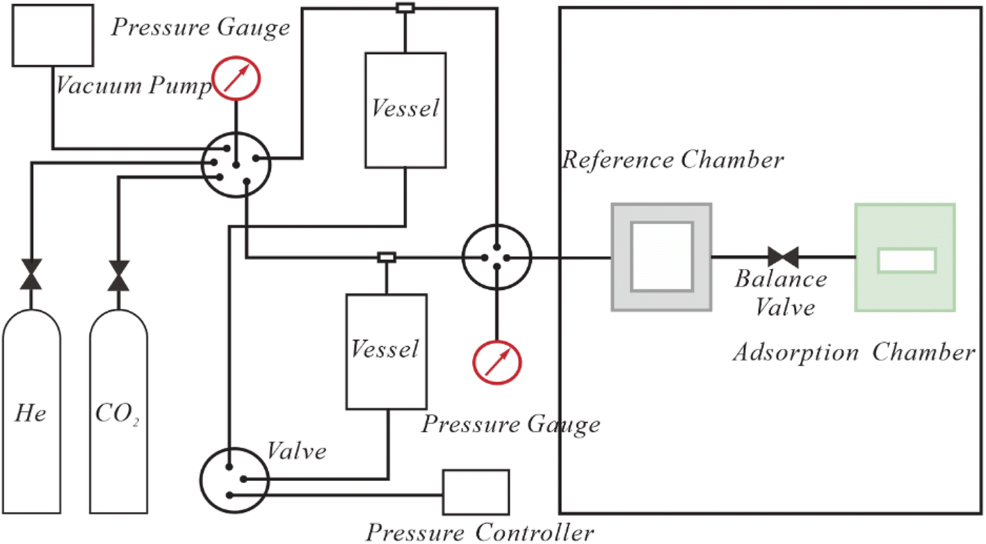
The study area is in the southeast edge of the Sichuan Basin, China. Six Longmaxi shale samples were collected from a fresh outcrop profile and numbered LMX-1 to LMX-6 from the bottom to top. Shale samples were grinded to 60–80 mesh size and dried at 105 °C for 24 h for the isothermal adsorption experiments. An aliquot of 10 g was needed for each sample. The adsorbate is CO2 with a 99.99% purity. The isothermal adsorption experiments were conducted by a Terratek-300 gas adsorption instrument (Fig. 1) in a volumetric method. The experimental pressure ranges from 0 to 6 MPa and the experimental temperature is 25 °C. Twenty experimental pressure points were set for each experimental sample (at intervals of 0.5 MPa and more for experimental pressure below 2 MPa). Prior to the adsorption experiments, the detection of instruments and circuits is necessary, including air tightness, pretreatment test, volume test of the reference chamber, etc. Then, the shale particles are put into the sample chamber, the balance valve is opened, and the isothermal adsorption experiments are conducted from low pressure according to the preset experimental pressure points. After 12 h of adsorption equilibrium at the first pressure point, the experimental pressure was raised and the subsequent pressure point was tested. Following the same procedure, the CO2 adsorption experiments of all pressure points and six experimental samples were completed.
 |
| | Fig. 1 Terratek-300 gas adsorption equipment. | |
2.2 Calculation and fitting of adsorption isotherms
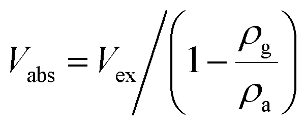
(1) The correction of absolute adsorption amount.
The results of the isothermal adsorption experiments are the excess adsorption amounts (Vex) (the excess amount of adsorbed phase density over bulk phase density), which underestimate the real adsorption capacity of shale gas reservoir. Therefore, they need to be corrected to obtain the absolute adsorption amounts (Vabs). The differences in Vex and Vabs are caused by the volume of the adsorption phase.21 Hence, an empirical formula (eqn. (1)) is used for the correction process.20
| |
 | (1) |
Vabs: the absolute adsorption amount, cm
3 g;
Vex: the excess adsorption amount, cm
3 g;
ρg and
ρa: the bulk density and adsorption phase density of CO
2, g ml
−1.
(2) Langmuir model.
The Langmuir model (eqn. (2)) is extensively used in the field of shale gas adsorption, which is based on the monolayer adsorption theory. The adsorption occurs until the adsorbent surface is covered with a layer of adsorbate.22 Additionally, the application of the Langmuir model needs to follow several assumptions, namely (i) the adsorbent surface is uniform, (ii) only monolayer adsorption occurs, and (iii) there is no force between the adsorbed molecules.23
| |
 | (2) |
P: experimental pressure, MPa;
VL and
PL: Langmuir volume and Langmuir pressure, cm
3 g
−1 and MPa.
(3) BET model.
The BET model (eqn. (3)) is the extension of the Langmuir model, which is based on multi-layer adsorption theory. Good fitting results with this model have been reported in the research of gas adsorption behavior in shale.18 According to the BET model, van der Waals forces exist not only between the adsorbent and the adsorbate, but also among the adsorbate (the latter is far lower than the former). Therefore, the adsorption is infinite.
| |
 | (3) |
Vm: saturated adsorption amount of monolayer, cm
3 g;
P0: saturated vapor pressure of adsorbate at experimental temperature, MPa;
c: a constant related to adsorption heat, dimensionless.
(4) DR and DA models.
DR and DA models (eqn. (4) and (5)) are also extensively employed in shale gas adsorption behavior, which are based on the micropore filling theory. Pore filling is regarded as the main adsorption behavior for gas in shale in these models, rather than molecular layer adsorption in the Langmuir and BET models.19 DA model is an improvement of DR model, an additional fitting parameter leads to improved fitting results.
| |
 | (4) |
| |
 | (5) |
a: structural heterogeneity constant of shale, ranging from 1 to 4.
3 Results and discussion
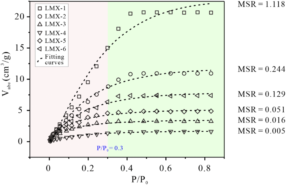
3.1 Fitting of experimental results
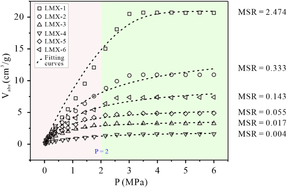
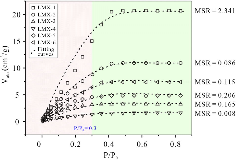
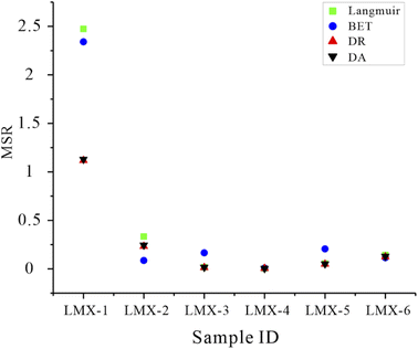
The experimental results are the excess adsorption amounts, in which the influence of adsorption phase density is ignored, resulting in lower values than the actual adsorption amount.24,25 The absolute adsorption amount corrected from the excess adsorption amount is used to characterize the real gas adsorption capacity of shale gas reservoirs (Fig. 2, 3, 4 and 5).26,27 All models presented fine applicability for CO2 adsorption data, with a high goodness of fit. The latter refers to the goodness of fit of the fitting line to the experimental data represented by MSR, and the goodness of fit increases with a smaller value (Fig. 6 and Table 1). With fitting of the Langmuir model to the data, MSR is in the range of 0.004–2.474 (0.504 on average). Langmuir adsorption is a monolayer adsorption based on the concepts of an ideal surface and ideal adsorption layer, which reflects ideal adsorption regularity.28–30 The high goodness of fit with the Langmuir model means that the monolayer adsorption theory is applicable for CO2 adsorption in shale gas reservoirs. However, the applicability of Langmuir model varies in the CO2 adsorption process. At low experimental pressure (P < 2 MPa), the deviation between the experimental data and the fitting curves is slightly larger than that for the subsequent adsorption process at higher experimental pressure (P > 2 MPa) (Fig. 2). This phenomenon suggests that the applicability of the monolayer adsorption theory at high experimental pressure is better. With fitting of the BET model to the experimental data, MSR ranges from 0.008 to 2.341, with an average of 0.487 (Fig. 3). BET adsorption is a multi-layer adsorption developed from the Langmuir model,31 its application also follows several assumptions. (i) The molecular adsorption on the adsorbent surface is an infinite layer, and the adsorption capacity and adsorption heat of the first layer are much larger than those of the other adsorption layers; (ii) the adsorption capacity and adsorption heat of the adsorption sites is equal; (iii) there is no interaction between the adsorbed molecules in the same layer.32,33 Generally, the goodness of fit and stability of the BET model are slightly higher than that of the Langmuir model (Fig. 6 and Table 1). The BET model performs better at high experimental pressure, which indicates that the molecular layer adsorption theory is more applicable for adsorption in mesopores and macropores in shale gas reservoirs, whereas its fitting for adsorption in micropores is slightly worse than for the former two types of pores.
 |
| | Fig. 2 The fitting of experimental data by the Langmuir model. | |
 |
| | Fig. 3 The fitting of experimental data by the BET model. | |
 |
| | Fig. 4 The fitting of experimental data by the DR model. | |
 |
| | Fig. 5 The fitting of experimental data by the DA model. | |
 |
| | Fig. 6 Goodness of fit of Langmuir, BET, DR, and DA models for CO2 adsorption data. | |
Table 1 The MSR values of the fitting models to the CO2 adsorption behaviors
| Goodness of fit |
Fitting model |
LMX-1 |
LMX-2 |
LMX-3 |
LMX-4 |
LMX-5 |
LMX-6 |
| MSR |
Langmuir |
2.474 |
0.333 |
0.017 |
0.004 |
0.055 |
0.143 |
| BET |
2.341 |
0.086 |
0.165 |
0.008 |
0.206 |
0.115 |
| D-R |
1.118 |
0.244 |
0.016 |
0.005 |
0.051 |
0.129 |
| D-A |
1.115 |
0.233 |
0.014 |
0.004 |
0.049 |
0.125 |
DA and DR models are established according to the micropore filling theory. The adsorption behavior of gas in micropores is obviously different from that in mesopores and macropores.34,35 The models are developed based on the adsorption potential theory. The adsorption area on the micropore surface is sufficient to form multi-molecular layer adsorption, and the gas adsorption density and adsorption intensity gradually decrease.34,35 The DA model presented the highest goodness of fit for the fitting of this model to the experimental data of all six samples, with MSR in the range of 0.004–1.115 (0.257 on average) (Fig. 4). The goodness of fit of the DR model is slightly lower than that of DA model, MSR ranges from 0.005–1.118, with an average of 0.261 (Fig. 4, 5 and 6). This difference is interpreted to be caused by the fact that the DA model has one additional fitting parameter than the DR model, resulting in a greater accuracy. Although the DA model is the best model, also a difference was recorded in the CO2 adsorption process. However, the deviation between the fitting curve and the experimental data is lower at low experimental pressure (P/P0 < 0.3) than at high pressure. This result suggests that the micropore filling theory is more suitable for the characterization of the CO2 adsorption behavior in the Longmaxi shale. Micropores are widely developed in the Longmaxi shale and dominate the specific surface area of pores which control the adsorption capacity of shale.36,37 This is because the organic matter in the Longmaxi shale is in the stage of high-over maturity. The source rock reached the generation peak of gaseous hydrocarbon and formed a great amount of expansion micropores in organic matter.38,39 Xie et al., Li et al., and Wang et al. also suggested that micropores are the main contributor to the specific surface area in over mature shale gas reservoirs, even with a ratio higher than 90%. Therefore, the micropore filling theory can better characterize the adsorption behavior of CO2 in shale.40–42
3.2 The goodness of fit of each isothermal adsorption model
The goodness of fit in the fitting process of the isothermal models is obviously different, hence, a specific criterion is needed to evaluate and measure it. Zhou et al., Wang et al. and Liu et al. suggested that the Average Relative Error, Akaike's Information Criterion and the Residual Sum of Squares (RSS) (eqn. (6)) could characterize the single point fitting degree and the entire fitting degree comprehensively.43–45 In this work, the quantity of the experimental pressure points is different, and thus, the mean square of residue (MSR) is more suitable. In Table 1, the MSR values of the models in the fitting process of CO2 were calculated.| |
 | (6) |
MSR: the mean square of residual; RSS: the sum of residual squares; DOF: degree of freedom, which equal n−1; Vabsi: the absolute adsorption capacity of the i-th pressure point, cm3 g; Vfiti: the fitting adsorption capacity of the i-th pressure point, cm3 g−1.
A smaller MSR value corresponds to a higher goodness of fit. MSR of the DA model is the smallest, followed by DR, BET, and Langmuir models (Fig. 6 and Table 1). These observations confirm that the micropore filling theory is the most probable adsorption mechanism for CO2 adsorption in the Longmaxi shale, whereas the performance of the molecular layer theory depends on the type of pores.
3.3 The controlling mechanism of goodness of fit in the fitting process
As mentioned above, the Langmuir, BET, DA, and DR models can be used to fit the CO2 adsorption behavior in shale, but an apparent difference in the goodness of fit is exhibited in the fitting process. The CO2 adsorption capacity and mechanism in the matrix are controlled by the pore structure of the Longmaxi shale, which leads to differences in the applicability of the four fitting models. Hence, the theory model of CO2 adsorption in shale was established to reveal the adsorption mechanism of CO2 in different pores (Fig. 7). Organic matter pores, intergranular pores, intragranular pores, and microfractures are widely developed in shale gas reservoirs, and they were divided into slit pores, plate pores, capillary pores, and ink-shaped pores.46,47 Slit pores are mainly intergranular pores and microfractures that are open at one end (Fig. 7a, a1, and a2). CO2 adsorption in slit pores consists of micropore filling in the closed end of pores and molecular layer adsorption at the open end of pores (Fig. 7a1). All four models are appropriate for the fitting of CO2 adsorption behavior in the slit pores. Plate pores are mainly interlay pores of clay minerals and microfractures that are open in all directions along the rough plane of the fracture (Fig. 7b, b1, and b2). Molecular layer adsorption dominates the CO2 adsorption behavior in plate pores (Fig. 7b1). The adsorption capacity and adsorption heat of the first layer are much larger than those of other adsorption layers. The Langmuir and BET models are suitable for the fitting of CO2 adsorption behavior in the plate pores. Capillary pores are mainly intergranular pores that are characterized by opening at both ends (Fig. 7c, c1, and c2). The cross-section of the pores is approximately circular and the longitudinal section is roughly rectangular. Micropore filling dominates CO2 adsorption behavior in the pores with a diameter lower than 2 nm, whereas molecular layer adsorption dominates adsorption in the pores with a diameter greater than 2 nm (Fig. 7c1). Ink-shaped pores are mainly organic matter pores characterized by a thin neck and a wide body (Fig. 7d, d1, and d2). The application of micropore filling and molecular layer adsorption is similar to that in capillary pores which is controlled by pore size (Fig. 7d1). Generally, hydrocarbon generation micropores in organic matter dominate the pore structure parameters (pore volume and specific surface area) of shale gas reservoirs.48,49 Furthermore, the DA model exhibits the highest goodness if fit (higher than that for the Langmuir and BET models) in the fitting process of CO2 adsorption in shale gas reservoirs.
 |
| | Fig. 7 Pore types and CO2 adsorption mechanisms in shale matrix. | |
(a), (b), (c), and (d) are the slit pores, plate pores, capillary pores, and ink-shaped pores of shale matrix; (a1)–(d1) and (a2)–(d2) are the corresponding pore structure and adsorption mechanism.50–53 InterG is intergranular, IntraG is intragranular; OM is organic matter, Cal is calcite, Ill is illite.
3.4 Potential of CO2 storage in deep shale gas reservoirs
Shale gas reservoir is one of the potential sequestration places of CO2 under the “dual carbon” ambition. Shale gas reservoirs are widely developed with a recoverable reserve of 214.5 × 10¹² m3 in the world, of which 31.6 × 10¹² m3 is in China.54 Moreover, the adsorption capacity of CO2 in shale is several to ten times higher than that of CH4.55,56 CO2 has a linear molecular configuration, smaller kinetic diameter, higher boiling point and critical temperature, higher polarity, and lower self-diffusion coefficient than CH4 and can thus easily penetrate through the pore throats and be absorbed by the pore walls.57–59 Additionally, organic geochemical and mineralogical composition characteristics are also significant controlling factors of the CO2 adsorption amount and adsorption affinity, especially the former. Xie et al. suggested that enhancing CH4 recovery and CO2 storage amount is controlled by total organic carbon content which provides a large pore volume and specific surface area, whereas the performance of clay is worse in high-over maturity Longmaxi shale gas reservoirs.60 Thus, more CO2 can be stored in shale gas reservoirs, especially in organic-rich shale, and the adsorbed CH4 will be displaced by CO2 to enhance shale gas recovery simultaneously. The absolute adsorption amount of CO2/CH4 ranges from 2.47 to 12.16 in my previous research, and the ratio increases with a rise in experimental pressure and decreases with a rise in experimental temperature.21 The geological reserve of deep shale gas (3000–4500 m) in China is approximately 101.67 × 10¹² m3.61 However, it is difficult to realize large-scale commercial development of deep shale gas. CO2 injection into shale gas reservoirs to fracture the reservoir, enhance CH4 recovery, and store CO2 is regarded as an environmentally friendly and cost-effective exploitation scheme.62,63 Under the situ condition of deep shale gas reservoirs, the adsorption ratio of CO2 to CH4 is approximately 4.5.21 Adsorbed gas accounts for 20–85% in shale gas reservoirs.64 Therefore, China's deep shale gas reservoirs can, in theory, store 91.5–388.89 × 10¹² m3 CO2 in an adsorbed state (eqn. (7) and (8)). Additionally, Liu et al. and Li and Elsworth suggested that CO2 sequestration in shale gas reservoirs is mainly in adsorbed and free states, of which the former accounts for more than 95% (Fig. 8), and the leakage risk of CO2 is less than 1% with a considerable sequestration security.65,66| | |
QCO2 = αCO2/CH4 × ACH4 × ρCO2
| (7) |
where QCO2 is the storage quantity of CO2 in deep shale gas reservoirs, m3; αCO2/CH4 is the adsorption ratio of CO2 to CH4 in shale under the situ condition of deep shale gas reservoirs; ACH4 is the adsorbed quantity of CH4 in deep shale gas reservoirs, m3; GR is the geological reserve of deep shale gas, m3; Pr is the proportion of adsorbed gas in shale gas reservoirs.
 |
| | Fig. 8 CO2 sequestration amount after injected into shale gas reservoirs.66 | |
4 Conclusion
(1) The fitting of the Langmuir, BET, DR, and DA models to the CO2 adsorption results are applicable, with varying goodness of fit for the different models. The fitting of the DA model is characterized by a lower MSR, followed by the DR, BET, and Langmuir models. The micropore filling theory is more suitable to describe CO2 adsorption behavior in shale than the monolayer adsorption and multi-layer adsorption theories, which are controlled by the widely developed micropores in organic matter.
(2) The CO2 adsorption mechanism is also affected by pore type, pore size, and pore structure. In slit pores, micropore filling and molecular layer adsorption dominate the CO2 adsorption process, whereas molecular adsorption prevails in plate pores. In capillary pores and ink-shaped pores, micropore filling or molecular layer adsorption depends on the pore size, with the former mainly occurring in pores of less than 2 nm, and the latter mainly in pores greater than 2 nm.
(3) Through the calculation of the adsorption selective coefficient of CO2 and CH4, and the geological reserve of deep shale gas in China, tillions of cubic meters of CO2 is in theory expected to be stored in an adsorbed state in China's deep shale gas reservoirs with a low leakage risk.
Author contributions
Experimental design and data analysis, Weidong Xie, Zhenghong Yu, Hua Wang, and Huajun Gan; writing and revision, Weidong Xie, Meng Wang, Veerle Vandeginste, Si Chen, Hua Wang, and Jiyao Wang.
Conflicts of interest
The authors declare no conflict of interest.
Acknowledgements
The authors gratefully acknowledge the supports of the Major Project Cultivation of CUMT (2020ZDPYMS09), the Fundamental Research Funds for National Universities, China University of Geosciences (Wuhan) and the Open Fund of the Key Laboratory of Tectonics and Petroleum Resources of Ministry of Education (TPR-2022-16).
References
- B. Ekwurzel, J. Boneham, M. W. Dalton, R. Heede, R. Mera, M. R. Allen and P. Frumhoff, Clim. Change, 2017, 144, 579–590 CrossRef.
- W. Xie, S. Chen, M. Wang, Z. Yu and H. Wang, Energy Fuels, 2021, 35, 18370–18384 CrossRef CAS.
- M. Godec, G. Koperna, R. Petrusak and A. Oudinot, Energy Procedia, 2014, 63, 5849–5857 CrossRef CAS.
- B. Jia, Z. Chen and C. Xian, J. Pet. Sci. Eng., 2022, 208, 109659 CrossRef CAS.
- C. Qin, Y. Jiang, J. Zhou, X. Song, Z. Liu, D. Li, F. Zhou, Y. Xie and C. Xie, Chem. Eng. J., 2021, 412, 128701 CrossRef CAS.
- J. Sun, C. Chen, Y. Zhang, W. Li and Y. Song, Chem. Eng. J., 2022, 430, 133172 CrossRef CAS.
- H. Chen, Y. Hu, Y. Kang, X. Wang, F. Liu and Y. Liu, J. Nat. Gas Sci. Eng., 2021, 93, 104033 CrossRef CAS.
- S. Memon, R. Feng, M. Ali, M. A. Bhatti, A. Giwelli, A. Keshavarz, Q. Xie and M. Sarmadivaleh, Fuel, 2022, 313, 122682 CrossRef CAS.
- L. Hou and D. Elsworth, Fuel, 2021, 292, 120188 CrossRef CAS.
- Y. Lu, Z. Xu, H. Li, J. Tang and X. Chen, Energy, 2021, 221, 119824 CrossRef CAS.
- Y. Feng, K. Haugen and A. Firoozabadi, J. Geophys. Res.: Solid Earth, 2021, 126, e2021JB022509 CAS.
- S. Wu, H. Ge, T. Li, X. Wang, N. Li, Y. Zou and K. Gao, International Journal of Rock Mechanics and Mining Sciences, 2022, 152, 105065 CrossRef.
- Y. Niu, C. Yue, S. Li, Y. Ma and X. Xu, Energy Fuels, 2018, 32, 3202–3210 CrossRef CAS.
- Z. Tao and A. Clarens, Environ. Sci. Technol., 2013, 47, 11318–11325 CrossRef CAS PubMed.
- F. A. Abdulkareem, A. Radman, G. Faugere, S. Sathiavelu, S. A. Irfan and E. Padmanabhan, J. Nat. Gas Sci. Eng., 2020, 81, 103423 CrossRef CAS.
- M. Wang, W. Xie, X. Dai and K. Huang, J. Nanosci. Nanotechnol., 2021, 21, 362–370 CrossRef CAS.
- W. Yu, E. W. Al-Shalabi and K. Sepehrnoori, Presented in Part at SPE Unconventional Resources Conference, April, The Woodlands, Texas, USA, 2014, p. D031S007R007, DOI: DOI:10.2118/169012-MS.
- K. Zeng, P. Jiang, Z. Lun and R. Xu, Energy Fuels, 2018, 33, 1785–1796 CrossRef.
- S. Rani, E. Padmanabhan, T. Bakshi, B. K. Prusty and S. K. Pal, J. Nat. Gas Sci. Eng., 2019, 68, 102903 CrossRef CAS.
- J. Zhou, M. Liu, X. Xian, Y. Jiang, Q. Liu and X. Wang, Fuel, 2019, 251, 293–306 CrossRef CAS.
- W. Xie, M. Wang and H. Wang, ACS Omega, 2021, 6, 18527–18536 CrossRef CAS PubMed.
- H. Kahraman, E. Pehlivan and A. Avci, lnternational Journal of Chemical Engineering and Applications, 2018, 9, 180–183 CrossRef CAS.
- X. Chen, M. F. Hossain, C. Duan, J. Lu, Y. F. Tsang, M. S. Islam and Y. Zhou, Chemosphere, 2022, 307, 135545 CrossRef CAS PubMed.
- W. Pang, Y. Wang and Z. Jin, Energy Fuels, 2021, 35, 8456–8493 CrossRef CAS.
- W. Shen, X. Li, T. Ma, J. Cai, X. Lu and S. Zhou, Phys. Fluids, 2021, 33, 063103 CrossRef CAS.
- R. Hu, W. Wang, J. Tan, L. Chen, J. Dick and G. He, Chem. Eng. J., 2021, 411, 128463 CrossRef CAS.
- J. M. Ekundayo, R. Rezaee and C. Fan, J. Nat. Gas Sci. Eng., 2021, 88, 103761 CrossRef CAS.
- I. Langmuir, J. Franklin Inst., 1917, 183, 102–105 CrossRef.
- S. Alafnan, A. Awotunde, G. Glatz, S. Adjei, I. Alrumaih and A. Gowida, J. Pet. Sci. Eng., 2021, 207, 109172 CrossRef CAS.
- A. E. Radwan, D. A. Wood, M. Mahmoud and Z. Tariq, Sustainable Geoscience for Natural Gas Subsurface Systemsed. D. A. Wood and J. Cai, Gulf Professional Publishing, 2022, ch. 12, pp. 345–382 Search PubMed.
- S. Brunauer, S. P. H. Emmett and E. J. Teller, J. Am. Chem. Soc., 1938, 60, 309–319 CrossRef CAS.
- K. Behere and S. Yoon, J. Chromatogr. B, 2021, 1162, 122434 CrossRef CAS.
- M. Kasprzyk, K. Czerwionka and M. Gajewska, Resour., Conserv. Recycl., 2021, 168, 105335 CrossRef CAS.
- M. Polanyi, Verh. Deut. Phys. Ges., 1914, 16, 1012–1016 CAS.
- M. Dubinin, Dokl. Akad. Nauk SSSR, 1947, 55, 327–329 CAS.
- H. Xu, W. Zhou, R. Zhang, S. Liu and Q. Zhou, Fuel, 2019, 241, 360–371 CrossRef CAS.
- X. Kong, S. Lu, D. Xiao, H. Fan, P. Mu and S. Jiang, Energy Fuels, 2021, 35, 4925–4942 CrossRef CAS.
- F. Shang, X. Tang, Q. Hu, Y. Wang, X. Meng and Y. Zhu, Energy Fuels, 2021, 35, 19496–19506 CrossRef CAS.
- L. Cheng, F. Guan, D. Liu, W. Yang and J. Sun, Geofluids, 2021, 6636156 Search PubMed.
- W. Xie, M. Wang and X. Dai, J. Henan Polytech. Univ., Nat. Sci., 2018, 37, 80–88 CAS.
- Y. Li, Z. Wang, Z. Pan, X. Niu, Y. Yu and S. Meng, Fuel, 2019, 241, 417–431 CrossRef CAS.
- Y. Wang, H. Cheng, Q. Hu, L. Liu, L. Jia, S. Gao and Y. Wang, J. Pet. Sci. Eng., 2022, 208, 109313 CrossRef CAS.
- S. Zhou, D. Zhang, H. Wang and X. Li, Mar. Pet. Geol., 2019, 105, 284–292 CrossRef CAS.
- C. Wang, S. Kong, Y. Liu and Y. Gao, Energy Fuels, 2020, 34, 4579–4586 CrossRef CAS.
- Z. Liu, D. Chen, S. Chang, X. Wei, X. Lv, R. Zuo and M. Han, Energy Fuels, 2021, 35, 13654–13670 CrossRef CAS.
- R. M. Slatt and N. R. O'Brien, AAPG Bull., 2011, 95, 2017–2030 CrossRef CAS.
- R. G. Loucks, S. C. Ruppel, X. Wang, L. Ko, S. Peng, T. Zhang, H. D. Rowe and P. Smith, Interpretation, 2017, 5, SF63–SF79 CrossRef.
- Y. Wang, L. Wang, J. Wang, Z. Jiang, C. Jin and Y. Wang, J. Nat. Gas Sci. Eng., 2018, 49, 56–65 CrossRef CAS.
- H. Nie, Z. Jin, C. Sun, Z. He, G. Liu and Q. Liu, Energy Fuels, 2019, 33, 8076–8100 CrossRef CAS.
- D. Liu, Z. Li, Z. Jiang, C. Zhang, Z. Zhang, J. Wang, D. Yang, Y. Song and Q. Luo, Journal of Asian Earth Sciences, 2019, 182, 103935 CrossRef.
- H. Guo, W. Jia, R. He, C. Yu, J. Song and P. Peng, Marine and Petroleum Geology, 2020, 121, 104622 CrossRef CAS.
- M. Saidian, L. J. Godinez and M. Prasad, J. Nat. Gas Sci. Eng., 2016, 33, 1095–1106 CrossRef CAS.
- X. Li, Z. Jiang, S. Jiang, Z. Li, Y. Song, H. Jiang, H. Qiu, X. Cao and Y. Miao, Mar. Pet. Geol., 2020, 111, 720–734 CrossRef CAS.
- B. W. UNCTAD, Community Development Agreements, World Bank Other Operational Studies, 2018 Search PubMed.
- A. Bemani, A. Baghban, A. H. Mohammadi and P. Ø. Andersen, J. Nat. Gas Sci. Eng., 2020, 76, 103204 CrossRef CAS.
- I. Klewiah, D. S. Berawala, H. C. Alexander Walker, P. Ø. Andersen and P. H. Nadeau, J. Nat. Gas Sci. Eng., 2020, 73, 103045 CrossRef CAS.
- A. A. Reznik, P. K. Singh and W. L. Foley, Soc. Pet. Eng. J., 1984, 24, 521–528 CrossRef CAS.
- C. R. Clarkson and R. M. Bustin, Int. J. Coal Geol., 2000, 42, 241–271 CrossRef CAS.
- J. Shi, L. Gong, S. Sun, Z. Huang, B. Ding and J. Yao, RSC Adv., 2019, 9, 25326–25335 RSC.
- W. Xie, M. Wang, S. Chen, V. Vandeginste, Z. Yu and H. Wang, Energy, 2022, 254, 124242 CrossRef CAS.
- J. Zhang, J. Tao, Z. Li, X. Wang, X. Li, J. Shengling, W. Dongsheng and Z. Xingxu, Nat. Gas Ind., 2021, 41, 15–28 Search PubMed.
- X.-D. Du, M. Gu, D. Shuo and X.-F. Xian, J. Energy Resour. Technol., 2017, 139, 012909 CrossRef.
- R. Iddphonce, J. Wang and L. Zhao, J. Nat. Gas Sci. Eng., 2020, 77, 103240 CrossRef CAS.
- J. B. Curtis, AAPG Bull., 2002, 86, 1921–1938 CAS.
- F. Liu, K. Ellett, Y. Xiao and J. A. Rupp, Int. J. Greenhouse Gas Control, 2013, 17, 111–126 CrossRef CAS.
- Z. Li and D. Elsworth, J. Pet. Sci. Eng., 2019, 179, 1037–1045 CrossRef CAS.
|
| This journal is © The Royal Society of Chemistry 2022 |
Click here to see how this site uses Cookies. View our privacy policy here. 
 Open Access Article
 This Open Access Article is licensed under a Creative Commons Attribution-Non Commercial 3.0 Unported Licence
 *c,
Veerle Vandeginsted,
Si Chen*ab,
Zhenghong Yuab,
Jiyao Wangc,
Hua Wangab and
Huajun Ganab
*c,
Veerle Vandeginsted,
Si Chen*ab,
Zhenghong Yuab,
Jiyao Wangc,
Hua Wangab and
Huajun Ganab