 Open Access Article
Electrophoretic deposition of hydroxyapatite/chitosan nanocomposites: the effect of dispersing agents on the coating properties
M. S. Gaafara,
S. M. Yakout b,
Y. F. Barakat
 a and
W. Sharmoukh
 *b
*b
aDepartment of Chemical Engineering, Tabbin Institute for Metallurgical Studies (TIMS), PO Box: 109 Helwan, 11421 Cairo, Egypt
bInorganic Chemistry Department, National Research Centre, Tahrir St, Dokki, Giza 12622, Egypt. E-mail: walidm@kth.se
First published on 28th September 2022
Abstract
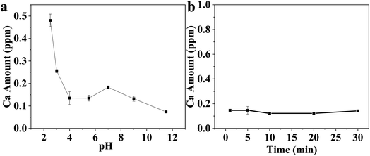
In this study, electrophoretic deposition (EPD) was used for the coating on titanium (Ti) substrate with a composite of hydroxyapatite (HA)-chitosan (CS) in the presence of dispersing agents such as polyvinyl butyral (PVB), polyethylene glycol (PEG), and triethanolamine (TEA). The materials were characterized using X-ray diffraction (XRD), transmission electron microscopy (TEM), scanning electron microscopy (SEM), zeta potential, and Fourier transform infrared (FT-IR) spectroscopy. The addition of PVB, PEG, and TEA agents improved the development of Ti coating during the EPD process. These additives increased the suspension stability and promoted the formation of uniform and compact HA/CS nanocomposite coatings on Ti substrates. The electrochemical polarization tests (e.g., potentiodynamic test) of the substrate with and without coating were investigated. Data analysis showed high corrosion resistance of Ti substrate coated with the HA/CS NP composite. The corrosion potentials displayed a shift toward positive values indicating the increase in the corrosion resistance of Ti after coating. In addition to measuring calcium ion release at various pH values and contact times at a biological pH value of 5.5, the stabilities of Ti substrates coated with HA/CS and different dispersing agents were also evaluated. Ti substrates with high anticorrosion properties may have a new potential application in biomedicine.
1 Introduction
In the field of biomedical implants, composite materials are currently being investigated.1 Ceramic coatings are commonly used on metal and metal alloy surfaces in composite implant materials.2 Generally, titanium alloy Ti6Al4V and commercially pure Ti are used because they are corrosion-resistant and mechanically strong.3 Increasing the surface activity of metal implants in living tissues through morphological, biochemical, or physicochemical modifications improves their biocompatibility.4 It is important to consider the composition and surface characteristics of implants when considering the tissue integration process and implant longevity. If metal implants corrode in vivo conditions, metal dissolution takes place and metal ions are released, causing adverse tissue reactions and even a lack of osseointegration.5 Biocompatibility could be improved by surface treatment and coating deposition on metal implants.6A great deal of attention has been paid to composites containing hydroxyapatite Ca10(PO4)6(OH)2 (HA).7 By introducing HA into the body environment, the so-called bone apatite can be formed.8 Nonetheless, pure HA is brittle, limiting its application.9 By mimicking natural bone composition, the ceramic/polymer composite material improves HA's mechanical properties. On the other side, chitosan (CS) is an attractive natural polymer for biomedical applications due to its biocompatibility, biodegradability, low toxicity, and good antimicrobial activity.10 In the regeneration process, CS was shown to serve as a base material for normal tissue growth during the tissue repair process.11 Among biopolymers, CS is excellent at forming films.12 As CS increases the adhesion between composite coatings and substrates, good biocompatibility of HA is combined with all the beneficial properties of CS, resulting in highly interesting composite coatings.13
Advanced composites are developed through component selection and material design.1 Unique properties of natural biomaterials are attributed to their hierarchical structure, graded composition, porosity, and orientation of their nanocrystals, among other factors.14,15 There have been several investigations on the development of laminated composites with alternate layers of HA and various substances, including bioglass,13 collagen,16 zirconia,17 silica,18 and polymers.19 According to the literature, HA/CS coatings were prepared by EPD using ethanol,20 isopropanol, methanol, or mixed ethanol/water baths.21 A great deal of attention has been paid to the application of EPD in the development of drug delivery devices.22 A bioactive coating containing several antibiotics was produced using EPD, including ciprofloxacin,23 ampicillin,24 moxifloxacin,25 vancomycin,26 tetracycline,27 and gentamicin.28
Bioceramics is a type of biomaterial that treats, augments, repairs, or replaces damaged or diseased hard tissue. In general, bioceramics can be divided into three subcategories: nearly bioinert, bioactive, and bioresorbable ceramics.29 Table 1 illustrates the advantages and disadvantages of each type. The mineral structure of bioceramics like HA, bioglass, and calcium phosphate makes them ideal for scaffolds, bone fillers, and coating agents. In comparison to polymers and metals individually, bioceramics produce a higher tissue response.30 HA is biocompatible enough to form a direct bond with the neighboring bone as an implant material. However, its poor mechanical properties prevent it from being applied to a wider range of applications. As a result, osseous implants are only used in non-load-bearing areas of the human body, such as middle ear ossicles.31 An improvement in mechanical properties is highly recommended in order to fully utilize HA-based implants for bioactive applications.32 Polymers, ceramics, metals, and composites are among the materials that can be deposited by EPD, but the substrate must be electrically conductive. EPD has many advantages, including the ability to homogenously coat porous and complex-shaped substrates at room temperature and with homogeneity of coatings. EPD is particularly useful for synthesizing various chitosan-based composites in a single step. Representative examples are the bioactive glass–chitosan composites that increase the osseointegration of 316 steel implants and their corrosion resistance.33,34 EPD allows us to collect nanocrystals as solid materials without added substances to investigate fundamental science (such as nanocrystal–nanocrystal interactions) and to study actual device fabrication approaches.35–37 Polymers can allow composite materials to be processed at low temperatures. These issues can be wiped out by the utilization of polymer-ceramic composites.38–40 The utilization of polymers offers the benefit of low-temperature preparation of composite materials.41 Critical attention has been devoted to HANPs/CSNPs. Remarkably, the most common binders in electrophoretic deposition are composed of non-ionic-type polymers such as polyvinyl alcohol, ethyl cellulose, polyacrylamide, etc.42
| Bioceramics | Artificial implants | Applications | Advantages | Disadvantages |
|---|---|---|---|---|
| Alumina | Knee, hip, shoulder, elbow, wrist | Reconstruction of the fractured part | High hardness, low friction | Weak in tension |
| Zirconia | Hip, tooth | Reconstruction of the fractured part | Corrosion resistant, hard, less friction | Friction problems, costly |
| Bioglass | Spinal fusion | Protect spinal cord | Biological fixation, bonding![[thin space (1/6-em)]](https://www.rsc.org/images/entities/char_2009.gif) |
Fragile |
| HA | Tooth, bone | Replacement of damaged teeth | Binds only to hard tissues | Sometime fragile |
Biomaterials such as HA and CS have been utilized in several advanced disciplines, including biotechnology and biomedicine.43–50 Among their applications are biomedical products, cosmetics, and food processing.42 The biomedical applications of HA are attributable to its mediocre mechanical properties.51–55 HA and Cs offered several advantages, including high biocompatibility, good thermal stability, high chemical resistance, mechanical quality, and antimicrobial properties that have been used in biotechnology. On the other hand, they form a composite for coating applications.56–58 HA or CS allowed the fabrication of suspensions with charged nanoparticles for coating applications using the EPD process. However, the suspension lacks high dispersion and good stability.
Herein, a nanocomposite mixture of CS and HA was synthesized and used for Ti coating via EPD. The synthesized samples were characterized using X-ray diffraction (XRD), transmission electron microscopy (TEM), scanning electron microscopy (SEM), energy dispersive X-ray (EDX), Fourier transforms infrared (FT-IR) spectroscopy, and Zeta potential. The composite was used for coating Ti substrate in the presence of dispersing agents such as polyethylene glycol (PEG), polyvinyl butyral (PVB), and triethanolamine (TEA). Dispersing agents like PEG, PVB, and TEA have been widely used to control the dispersion and morphology of the nanoparticles. Dispersing agents have the unique ability to self-organize in solution, which can modify their interfacial properties and make particles of different characteristics more compatible.59 Our work is aimed at enhancing the efficiency of the nanoparticle system of HA blended with CS. This is done via the addition of three different dispersing agents, such as PEG, PVB, and TEA, during the preparation of the nanocomposite. The purpose of this study is to investigate the influence of different dispersing agents on the structure, morphology, and anticorrosion properties of the nanocomposite. The results obtained in this work allow us to optimize the EPD coating method of HA/CS on the Ti substrate system to tune the properties of the nanocomposites.
2 Materials and methods
2.1. Materials
All chemicals were purchased from international delivery companies and used without purification. Chitosan (MWt = 200![[thin space (1/6-em)]](https://www.rsc.org/images/entities/char_2009.gif) 000) with about 85% deacetylation was purchased from Aldrich and dissolved in a 1% acetic acid solution. Sodium tripolyphosphate (STPP) (367.864 g mol−1) and ethanol solution were bought from Sigma Aldrich Co. (USA). N,N dimethylformamide (DMF; 99%), triethanolamine ≥99.0% (GC) (TEA) (149.188 g mol−1), polyethylene glycol (PEG; MWt 20
000) with about 85% deacetylation was purchased from Aldrich and dissolved in a 1% acetic acid solution. Sodium tripolyphosphate (STPP) (367.864 g mol−1) and ethanol solution were bought from Sigma Aldrich Co. (USA). N,N dimethylformamide (DMF; 99%), triethanolamine ≥99.0% (GC) (TEA) (149.188 g mol−1), polyethylene glycol (PEG; MWt 20![[thin space (1/6-em)]](https://www.rsc.org/images/entities/char_2009.gif) 000), polyvinyl butyral (PVB, MWt = 95
000), polyvinyl butyral (PVB, MWt = 95![[thin space (1/6-em)]](https://www.rsc.org/images/entities/char_2009.gif) 000–110
000–110![[thin space (1/6-em)]](https://www.rsc.org/images/entities/char_2009.gif) 000), nitric acid (HNO3, 69%), and hydrofluoric acid (HF, 40%) were delivered from LOBA Chem (India), Across organic (USA), BDH (England), and POCH (Poland).
000), nitric acid (HNO3, 69%), and hydrofluoric acid (HF, 40%) were delivered from LOBA Chem (India), Across organic (USA), BDH (England), and POCH (Poland).
2.2. Preparation of CS nanoparticles (NPs)
The process used to prepare chitosan nanoparticles (CSNPs) is based on the ionic gelation of sodium tripolyphosphate (STPP) and CS at ambient temperature.60 According to the literature, different concentrations (0.10, 0.30, 0.50, 0.80, and1.0%) of CS were prepared.47,48,61 In a solution of 2% (20/80) acetic acid/water, CS (0.5 g per 100 mL) was dissolved under mechanical stirring for 2 h. Upon complete dissolution, the pH of the suspension was changed to 4.6–4.8 using 0.1 M NaOH (3 mL). A variety of TPP concentrations (0.25, 0.50, 0.75, and 1.0 mg per mL−1) were prepared. An aqueous solution of TPP (5.0 mg per 20 mL) was added dropwise with continuous magnetic stirring at room temperature to 40 mL of CS solution. The mixture was held in ionic gelation for 6 h to complete, and the milky emulsion was attained. The suspension was centrifuged for 15 min at 6000 rpm, and supernatants were discarded. The precipitated samples were thoroughly rinsed with distilled water three times to remove traces of the unreacted compound, followed by centrifugation. After that, the washed precipitate of CS NPs was freeze-dried for 12 h. For further examination, the dried powder of CS NPs was kept at 4 °C.2.3. Preparation of HA
HA was synthesized following the literature.62 In this synthesis process, 100 mL of phosphoric acid solution (H3PO4, 0.3 M) was added at a rate of two drops per second at room temperature to an equivalent volume of calcium hydroxide suspension (Ca(OH)2; 0.5 M). During the precipitation process, the pH value was kept above 10 by adding ammonium hydroxide (NH4OH). The resultant precipitate was observed in the mother suspension for five days and eventually washed with methanol (5 mL) and isopropyl alcohol three times and dried using a high vacuum.2.4. EPD of HA and CS nanocomposite
The nanocomposite of HA and CS was prepared as follows: EPD was performed from suspensions of 8 g L−1 HANPs in a mixed solution of DMF and ethanol (30![[thin space (1/6-em)]](https://www.rsc.org/images/entities/char_2009.gif) :
:![[thin space (1/6-em)]](https://www.rsc.org/images/entities/char_2009.gif) 20 mL), containing 0.5 g L−1 CSNPs. The suspension mixture was magnetically stirred for 10 min and ultra-sonicated for 30 min to achieve a homogeneous dispersion of HA and CS. A sequence amount of TEA, PEG, and PVB was added to the mixture suspensions. Then, the suspension mixtures were applied to the EPD technique at room temperature. Titanium (Ti) sheets (2 × 1 × 0.25 cm3) were cleaned with acetone for 30 min in an ultrasonic bath before being used. The substrates were etched with a 5% solution containing nitric acid and hydrofluoric acid for 10 min. After that, the etched layer was rinsed in deionized water and dried with nitrogen gas. The etching process is a routine step for the coating process. It aims to remove the oxides formed during storage and clean the surface from debris to ensure the coating of the Ti substrate with HA/Cs composite. The starting surface must generally be reproducible and homogeneous to have reproducible surface preparation processes. The purpose of cleaning is to achieve desirable processing and film/coating properties. As a separate process, external cleaning is performed in a controlled environment outside of the deposition system. The etchant of titanium with hydrofluoric acid alone produces hydrogen gas as a by-product. The addition of nitric acid increases the rate of etching, eliminates hydrogen gas formation, and produces a smoother finish on the surface. Nitric acid prevents the titanium surface from becoming rough and nodular.63,64 The electrodeposition was applied for 10 min using an applied voltage of 30 V following the optimized values in previous reports.65–67 The electrochemical cell for the deposition included cathodic substrate commercially pure titanium (99.66%). The substrate was centered between two parallel platinum counter electrodes, and the distance between the cathode and counter electrode was held at 3 cm. The sample was characterized to obtain visual observations, the coating deposition weight, and adhesive tape to determine the coating's adhesive properties. As part of the tape stripping experiment, the tape was fully laminated onto the sample surface and peeled off three times.
20 mL), containing 0.5 g L−1 CSNPs. The suspension mixture was magnetically stirred for 10 min and ultra-sonicated for 30 min to achieve a homogeneous dispersion of HA and CS. A sequence amount of TEA, PEG, and PVB was added to the mixture suspensions. Then, the suspension mixtures were applied to the EPD technique at room temperature. Titanium (Ti) sheets (2 × 1 × 0.25 cm3) were cleaned with acetone for 30 min in an ultrasonic bath before being used. The substrates were etched with a 5% solution containing nitric acid and hydrofluoric acid for 10 min. After that, the etched layer was rinsed in deionized water and dried with nitrogen gas. The etching process is a routine step for the coating process. It aims to remove the oxides formed during storage and clean the surface from debris to ensure the coating of the Ti substrate with HA/Cs composite. The starting surface must generally be reproducible and homogeneous to have reproducible surface preparation processes. The purpose of cleaning is to achieve desirable processing and film/coating properties. As a separate process, external cleaning is performed in a controlled environment outside of the deposition system. The etchant of titanium with hydrofluoric acid alone produces hydrogen gas as a by-product. The addition of nitric acid increases the rate of etching, eliminates hydrogen gas formation, and produces a smoother finish on the surface. Nitric acid prevents the titanium surface from becoming rough and nodular.63,64 The electrodeposition was applied for 10 min using an applied voltage of 30 V following the optimized values in previous reports.65–67 The electrochemical cell for the deposition included cathodic substrate commercially pure titanium (99.66%). The substrate was centered between two parallel platinum counter electrodes, and the distance between the cathode and counter electrode was held at 3 cm. The sample was characterized to obtain visual observations, the coating deposition weight, and adhesive tape to determine the coating's adhesive properties. As part of the tape stripping experiment, the tape was fully laminated onto the sample surface and peeled off three times.
2.5. Coating characterization
An electrochemical corrosion test of uncoated and coated samples was carried out under simulated body fluid (Ringer's solution), and a saturated calomel electrode (SCE) was used as the reference electrode. To mimic the environment of the human body, the temperature of the test is 37 °C if materials are being tested for implants. Ringer physiologic solution contains: potassium chloride (0.40 g); calcium chloride dehydrate (0.27 g); sodium chloride (6.00 g); sodium lactate (3.17 g); water for injections (up to 1000 ml). The exact pH value of Ringer's solution is pH 7.3–7.4. The area of the coated surface exposed to the corrosion study was 1 cm2. The other sides of the electrode and its edges were masked with lacquer and were dried in air. The electrodes were further dipped into the electrolyte solution to study the corrosion process. Potentiodynamic polarization (PDP), open circuit potential (OCP), and electrochemical impedance spectroscopic studies (EIS) were carried out on uncoated and coated Ti substrate samples.The critical parameters like corrosion potential (Ecorr), corrosion current (icorr), polarization corrosion resistance (Rb), and corrosion rate were evaluated from the polarization curves. The corrosion rate, CR in mm per year, is given by CR = 3.27 × 10⁻³icorrEw/p where icorr is the corrosion current density in micro A cm−2, Ew is the equivalent weight of the corroding metal in grams, and p is the density of the corroding metal in g cm−3. The corrosion tests were performed three times for each group. The electrochemical experiments were performed using A VOLTA LAB 40 (Model PGZ301) with the aid of commercial software (VoltaMaster 4 version 4.08) or Corrtest® (CS350, Wuhan, China). The samples were immersed in Ringer solution, and the OCP was monitored for 1 h. The potentiodynamic polarization scans were carried out with a scan rate of 1 mV s−1 ranging from −0.5 V to 1.0 V vs. SCE.
The HA and CS synthesized powders were investigated in terms of particle size and shape using a transmission electron microscope (TEM, JEOL, Japan). The microstructure and surface morphology characterization of Ti substrates after modifications were carried out using scanning electron microscopy (SEM, JEOL, JSM 5410, Japan). The chemical analysis of the surface was performed using energy dispersive spectrometry (EDS, Model 6587, Pentafet Link, Oxford microanalysis group, UK). The phase composition of the synthesized powders and coatings was proven through X-ray diffraction (XRD) (Bruker AXS-D8 X-ray diffractometer, ADVANCE, Germany). Fourier transform infrared spectroscopy (FT-IR) was recorded using a Nicolet spectrophotometer (model 6700). A Zetasizer Nano ZS90 (Malvern Instruments Ltd., UK) was used to analyze the electrokinetic properties of HA and CS in both suspensions. The calcium ion release from the Ti substrate was evaluated at different pH values in the range of 2.2–12. The release was also evaluated at pH 5.5. The calcium concentration was measured using inductively coupled plasma-optical emission spectrometry (ICP-OES, Thermo Scientific, USA). The corrosion resistance of the coated Ti specimens was tested, determining polarization curves. A saturated calomel electrode (SCE) and a Pt wire were used as reference and counter electrodes, respectively. After that, the coated Ti substrate was dried at room temperature for 24 h. Etched Ti substrate and Ti-substrate coated with HA/CS were used as working electrodes using different dispersing agents. Ringer's solution was used as an electrolyte. EIS was measured for etched Ti and Ti coated with HA/CS using TEA, PVB, and PEG. Two significant parameters were obtained based on EIS: coating resistance and corrosion rate. A 0.5 mV s−1 amplitude sinusoidal voltage is used for measurements over a wide frequency range of 100 kHz to 0.01 Hz. The measurements were recorded using a potentiostat (CS350, CorrTest® Electrochemical Workstation, Wuhan, China).68
3 Results and discussion
3.1. TEM, dynamic light scattering (DLS), and zeta potential study
The morphology and particle size of CS and HA were determined using TEM (Fig. 1a and b). TEM image of CS showed irregular particles with a size of 25–50 nm (Fig. 1a). HA nanoparticles display a needle-like morphology Fig. 1b. The long axis of the needles corresponded to the c-axis of the hexagonal HA structure. The average length of the crystals was about 200 nm, and the average aspect ratio was 8. The small size of the HA nanoparticles enabled the formation of well-dispersed suspensions, which were stable against sedimentation for 1–2 days. From Fig. 1c results, it can be concluded that the average particle size of CS was larger than 180 nm. It is also observed that the poly-dispersity of CS nanoparticles is 0.11 revealing the homogeneity of the as-prepared particle of CS. However, HA has a smaller size (55 nm), which is smaller than CS with mono-dispersity (PDI = 0.078). The particle size using DSL is usually measured in liquid. Thus, the measured value of the particle corresponds to the hydrodynamic particle size. It is important to remember that solvent molecules will interact with the material through a variety of non-covalent interactions (e.g., hydrogen bonds, van der Waals interactions, pi–pi stacking). It may be observed that the particle size recorded by DLS is different in different solvents or mixtures thereof due to the different solvation properties of these solvents (e.g., water is both a hydrogen bond donor and acceptor, whereas THF is only a hydrogen bond acceptor), and therefore differing solvation properties can affect the size of particles. In contrast, the TEM image shows the particle size under vacuum, i.e., no solvent, and particles may undergo shrinking due to the vacuum.69,70 Fig. 1d shows the surface charge of the as-prepared CS and HA. As known, the zeta potential provides a predictor of polymer nanoparticle stability.71 As the zeta potential increases to ±25 mV, the nanoparticles become more stable. From Fig. 1d, it is observed that the zeta potential value for CS and HA is 49 mV and −32 mV. Therefore, the formed CSNPs were stabilized and quietly protected from agglomeration. The positive action of these prepared CS shows that the emulsions were stabilized by the hydrogen bonds between the amino groups and hydroxyl groups of CS and water molecules, in which water molecules serve as proton providers while the amino groups are the receivers. The negative signal of HA could be attributed to the negative charge bearing oxygen atoms. In EPD, pH is affected by the agitation of electrolytes and the high current density as hydrogen is evolved at the electrode surface. As a result of its deacetylation to more than 85%, CS is insoluble in alkaline conditions but easily dissolves in the organic acid and has a positive charge. As the electrolyte suspension is placed in the electrochemical cell, the HA precipitates as CaP on the cathodic substrate, increasing the pH. The positive charge on the CS moves to the cathode, where the pH has become alkaline, depositing on the substrate and HA. The optimal pH for the protonation of chitosan depends on its solubility at different pH levels. CS undergoes protonation at pH values below 6. The solution becomes insoluble when the pH value exceeds 6.5. Furthermore, high pH values reduce chitosan's electrostatic repulsion, resulting in fibers, films, or hydrogels forming as an interpolymer. It is known that dispersing agents can adsorb onto the surface of compound nanoparticles. Furthermore, cationic polyelectrolytes such as PEG, PVB, and TEA have inherent binding properties.72,73 Thus, it can be used for charging particles and electrophoretic filings, and the positively chargeable nanoparticles provide electrophoretic transport of polymeric molecules to form deposits on the cathodic substrates.74,75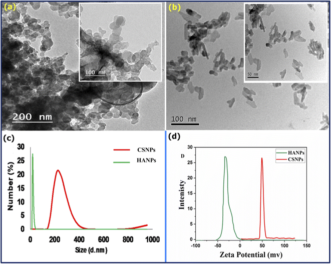 | ||
| Fig. 1 TEM image of (a): CS and (b): HA, (c) particle size analyzer, and (d) zeta potential of CS and HA. | ||
3.2. SEM analysis
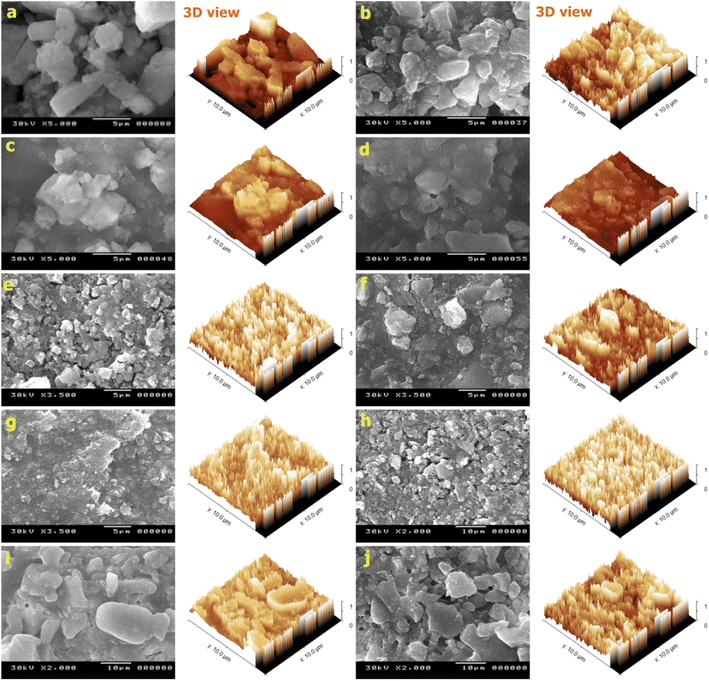
To outline the change in the surface morphology of the nanocomposite after the addition of dispersing agents (PVB, PEG, and TEA), SEM was used to characterize the surface morphology of the HA/CS nanocomposite. It is depicted that in the nanocomposite before treatment with PVB, the HA/CS has a small nanoparticle size but with aggregated shapes (Fig. 2a). The nanocomposite was treated with different concentrations of PVB, (B): 0.25 g L−1, (C): 0.5 g L−1, and (D): 1 g L−1 (Fig. 2b–d). It is seen that using PVB (0.25 g L−1, 0.5 g L−1), as shown in Fig. 2(b and c), covered the particles of HA/CS nanocomposite with a thin layer. Additionally, HA/CS nanocomposite is wholly covered using 1 g L−1 of PVB (Fig. 2d). This causes uniformity in the coating layer. The particles become more packed and denser, affirming that PVB can enhance the dispersion of this nanocomposite at room temperature, causing the formation of a homogeneous solution suitable for the EPD process. Moving to the effect of PEG on the surface morphology of the nanocomposite (Fig. 2e–g), it is remarkable that increasing the concentration of PEG from 0.25 g (Fig. 2e) to 0.5 g (Fig. 2f) leads to a change in the surface appearance of the HA/CS nanocomposite. Upon increasing the concentration of PEG to 1 g (Fig. 2g), the surface of HA/CS is changed due to the potential effect of PEG at such a concentration, which causes uniformity of the coating layer, and the particles become more packed with finer particle size. Meanwhile, Fig. 2(h–j) displays the SEM images of the surface morphology nanocomposite coatings deposited on titanium substrate from HA/CS nanocomposite treated with triethanolamine (TEA of 2, 4, and 10 mL L−1), which act as a dispersant at an applied voltage (30 V) for 10 min. It is demonstrated that HA/CS nanocomposite coating is free from cracks and has densely packed layers (Fig. 2h–j). It is also illustrated that increasing the concentration of TEA above 4 mL L−1 does not affect the surface morphology of the nanocomposite, which could be ascribed to the impact of both HA/CS mixtures with TEA as dispersing and charging agent, in addition to effectively breaking up the agglomerates existing in the as-received coating to produce a colloidal stable suspension. Fig. 3 shows the changes in (CS/HA) PEG coating film to the Ti substrate before and after tape stripping through high and low magnification SEM micrographs. Upon pressing the pressure-sensitive tape onto the film, it is rapidly stripped off. There are three possible removal scenarios: (a) completely removing the film from the substrate, (b) not removing the film, or (c) partially removing or patching the film.76,77 As shown in Fig. 3, the film is partially removed, which suggests good adhesion in this case. Clearly, this is a highly qualitative test, and it can be used to distinguish between cases with very poor adhesion and those with better adhesion to the substrate.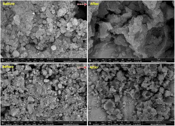 | ||
| Fig. 3 High and low magnification SEM micrographs of CS/HA(PEG) coating film before and after the peel-off tape. | ||
3.3. XRD and EDS study
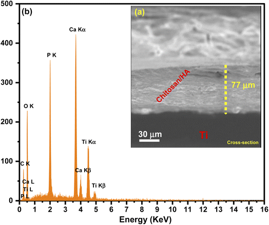
For further structural confirmation, XRD was used to examine the crystallinity of the prepared nanocomposites (HA/CS) coated with dispersing agents PVB, PEG, and TEA. Fig. 4 shows the XRD of HA/CS coated with three dispersing agents labeled HA/CS/PVB, HA/CS/PEG, and HA/CS/TEA. In all three XRD graphs (Fig. 4a), it is noted that HA/CS samples have diffraction peaks that correspond to the standard for hydroxyapatite. Additionally, the XRD pattern of HA reveals that the HA powders are crystalline, with the primary phase of hexagonal HA with a diffraction peak at 2θ = 31.5970°. The Powder Diffraction File (JCPDS-ICDD, 44-1294) verifies the XRD pattern as hydroxyapatite. It is depicted that the calculated crystallite sizes of the as-synthesized nanocomposite coated with PVB, PEG, and TEA are about 7.7 nm, 9.17 nm, and 18.9 nm from the Scherrer formula for all three examined samples, respectively. The peaks of CS are diminished, which may be related to the encapsulation effect for CS by HA or due to the lower amount of CS in the prepared nanocomposite and the amorphous nature of chitosan.42 In Fig. 4b, the EDS spectrum was used to determine the elemental analysis of each nanocomposite based on CS/HA nanocomposite treated with PVB, PEG, and TEA as dispersing agents. It is illustrated from the EDS spectra of HA/CS nanocomposite coated with PVB (1g L−1) at applied voltage 30 V and 10 min of deposition that the presented elements are Ca and P with weighing ratios equal to 30.6% and 18.55%, respectively. These mentioned weights (%) are changed to 28.30% and 16.89% when the nanocomposite of HA/CS has been coated with an emulsifying agent PEG (1 g L−1) under the same mentioned conditions of applied voltage and time of deposition. Deposition times of 5 to 15 min were used for HA/CS suspensions with additives under constant voltage conditions in the range from 10–50 V. During EPD, voltage and deposition time were used to control the thickness of the coating on the Ti substrate. The coatings were prepared in a uniform composition with a thickness of up to 90 μm. At the optimal potential of 30 V, we were able to achieve a maximum thickness of 90 μm in just 10 min. As a result, different HA/CS suspensions and EPD conditions produced various quality deposited films. Even with a 0.1 g L−1 concentration, the least concentrated solution showed little deposition and inhomogeneity, regardless of where or how long the coating was deposited. However, the 1.0 g L−1 suspension produced films that, after 10 minutes, reached a thickness of 90 μm showed high quality and homogeneity. A high-quality coating was obtained at 30 V. High voltage results in more homogeneous HA/CS coatings. Our experiments revealed that thick films of thickness <5 μm were not uniform when removed from the suspension and tended to detach from electrodes.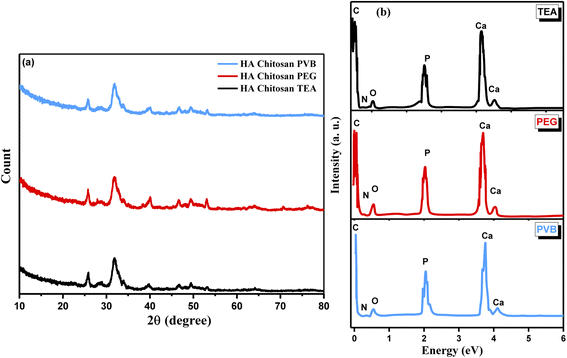 | ||
| Fig. 4 (a) XRD pattern and (b) EDS spectra of HA/CS treated with 1 g L−1 PVB, 0.5 g L−1 PEG, and 4 mL per LTEA. | ||
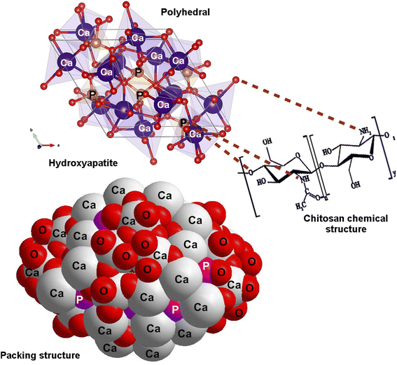
Meanwhile, after nanocomposites were treated with TEA (4 ml L−1) and submitted to EDS analysis, it was found that there are two different weight ratios of Ca and P equal to 31.3% and 18.5%, respectively. The cross-section images of HA/CS revealed the formation of uniform and dense coatings with a thickness of 77 μm, and the absence of any delamination or mismatch at the coatings/Ti substrate interface could be due to the alkali-treatment of the substrates. Indeed, EDX spectra of HA/CS show the presence of [Ca] and [P] elements with Ti substrate (Fig. 5). Fig. 6 illustrates the polyhedral and packing structure of HA and the CS chemical structure of HA/CS composite. A variety of interaction schemes have been investigated between CS and HA (Ca10(PO4)6(OH)2) involving OH, O, NH2, Ca2+, and/or P5− groups. The OH of Ca(OH)2 is coordinated with N–H of CS unit 2, while the other one is coordinated with the OH of CS unit 1. Based on the hypothesis that Ca2+ is directly linked to OH− in HA, Fig. 6 was designed. It may also be concluded that Ca2+ is freely interacting with CS as indicated in the literature.78,79
3.4. FT-IR study
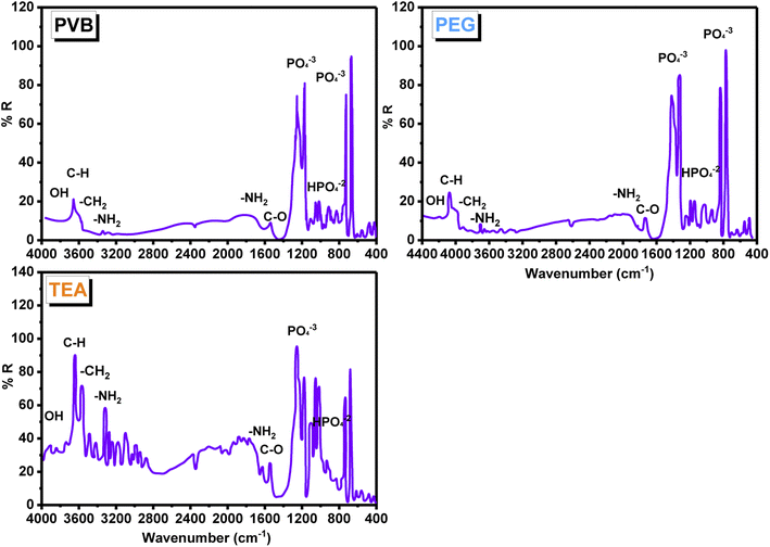
An FT-IR study, using the KBr technique (Fig. 7), was used to investigate the changes in the composites of CS/HA with dispersing agents (PEG, PVB, and TEA). Based on the IR spectra of all composites, phosphate ions and hydroxyl group content of HA were demonstrated. The broadband appearing above in the region 3500 cm−1 is assigned to the vibrational band of OH− groups in HA. The spectra indicate the presence of strong absorption bands around 900 and 1200 cm−1, corresponding to the PO43− ions, carbonated ions on 850–1500 cm−1, and carbon dioxide in the range of 2200–2300 cm−1 of HA. Those belong to the stretching and vibration bending of the PO43− group (v1, v3 PO43−). The absorption band at 670 cm−1 corresponds to the bending vibration m4 of O–P–O in HA, whereas the peaks at 1211 and 1126 cm−1 correspond to the stretching vibration m3 of P–O in HA. The band at 1029 cm−1 is due to HPO4−2 groups. All composites displayed two weak IR bands at 3400–3500 cm−1 resulting from the NH2 group of CS. Furthermore, two medium bands at 1635 and 1550 cm−1 are characterized by CS, where the first band is caused by the C![[double bond, length as m-dash]](https://www.rsc.org/images/entities/char_e001.gif) O stretching of amide I, and the second band is driven by the N–H bending of amide II. The IR spectra of TEA shows strong bands that are shifted at 3622 and 3555 cm−1, which indicates the presence of strong H-bonds between the OH groups of TEA and their corresponding in HA groups. As a result of CH2 symmetrical deformation, the IR of PEG HA/CS has two strong characteristic bands at 1421 and 1320 cm−1. There is a strong band at 1250 cm−1 attributable to the stretching of PEG and PVB along the C–O axis. Highly shifted values indicate that HA forms an H-bond with CS heteroatoms. It appears as the distinguishing bands of HA, such as OH and the phosphate anion bands. An FT-IR analysis combined with XRD analysis clearly showed the presence of HA in CS.80–83
O stretching of amide I, and the second band is driven by the N–H bending of amide II. The IR spectra of TEA shows strong bands that are shifted at 3622 and 3555 cm−1, which indicates the presence of strong H-bonds between the OH groups of TEA and their corresponding in HA groups. As a result of CH2 symmetrical deformation, the IR of PEG HA/CS has two strong characteristic bands at 1421 and 1320 cm−1. There is a strong band at 1250 cm−1 attributable to the stretching of PEG and PVB along the C–O axis. Highly shifted values indicate that HA forms an H-bond with CS heteroatoms. It appears as the distinguishing bands of HA, such as OH and the phosphate anion bands. An FT-IR analysis combined with XRD analysis clearly showed the presence of HA in CS.80–83
3.5. Study of addition of PVB, PEG, and TEA
Firstly, our work aims to design and study the effect of different types of dispersing agents. Polymers can be used to study the efficiency of nanocomposites based on HA and CS. According to Fig. 8, deposition yield and thickness change as a function of PEG, PVB, and TEA content. The addition of PEG to the nanocomposite resulted in an increased deposition yield, higher conductivity, and lower voltage drops, indicating the co-deposition of HA and CS. The highest deposition weight and the coating thickness were observed at 0.65 g L−1 with PEG as dispersing agent (Fig. 8a and B). A further increase in PEG concentration led to a decrease in the deposition rate.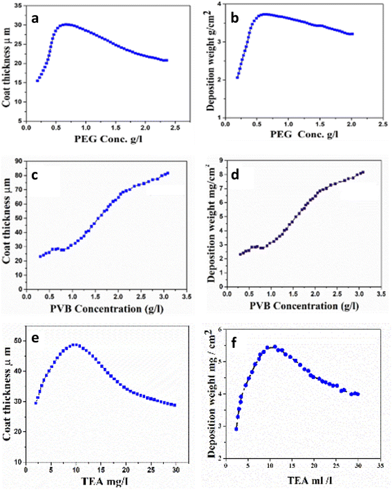 | ||
| Fig. 8 Effect of concentration of PEG, PVB, and TEA on (a) deposition weight (b) thickness at 30 V for 10 min, in mixture suspension, and (c–f) for PVB, and TEA. | ||
The solution was stirred after the addition of PVB as a dispersing agent to the nanocomposite above and kept under stirring until complete homogeneity, followed by the EPD process. It was observed that PVB plays an essential role in the coating thickness and deposition weight of the nanocomposite, as shown in Fig. 8c and d. The deposition weight and coating thickness (Fig. 8c and d) and coating thickness increase using PVB compared to the nanocomposite in the absence of PVB as a dispersing agent. The data proved that the maximum thickness of the deposited layer increases by increasing the concentration of PVB. Fig. 8e and f show that upon the addition of TEA, deposition weight and coat thickness increase to reach the highest point at 10 mL L−1. This observation is attributed to the rise in conductivity by TEA. Therefore, the positive charge increases and repulsion between particles increases, resulting in decreasing the deposition weight and coating thickness.84,85
3.6. Electrochemical measurements
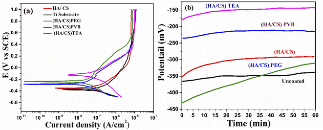 | ||
| Fig. 9 (a) Potentiodynamic polarization curves and (b) OCP curves for Ti with and without the coating. | ||
| Conditions | −Ecorr (mV) | icorr (μA cm−2) | Rp (k ohm.cm2) | βa (mV) | βc (mV) | Corr. rate (mm year−1) |
|---|---|---|---|---|---|---|
| a Standard deviations are between brackets. | ||||||
| Uncoated Ti | 386.8 (±7.7) | 0.0873 (±0.001) | 0.784 (±0.06) | 233.3 (±6.6) | −93.9 (±5.4) | 7.6068 × 10⁻⁴ (±8.84314 × 10⁻⁶) |
| HA/CS coated Ti | 355.0 (±5) | 0.0884 (±0.0013) | 1.242 (±0.12) | 230.2 (±4) | −120.3 (±5) | 7.70265 × 10⁻⁴ (±1.11245 × 10⁻⁵) |
| PEG addition | 239.0 (±7.7) | 0.0187 (±0.001) | 7.833 (±0.73) | 295.9 (±7.5) | −157.1 (±7.7) | 1.33025 × 10⁻⁴ (±6.53989 × 10⁻⁶) |
| TEA addition | 130.8 (±6) | 0.0296 (±0.001) | 5.463 (±0.36) | 190.3 (±3) | −122.7 (±5) | 2.57917 × 10⁻⁴ (±8.84314 × 10⁻⁶) |
| PVB addition | 280.2 (±9.5) | 0.0153 (±0.001) | 7.251 (±0.21) | 232.4 (±6.6) | −121.5 (±3.5) | 1.33025 × 10⁻⁴ (±6.53989 × 10⁻⁶) |
| Composite | Fabrication method | icorr (μA cm−2) | Biological studies | Substrate | Ref. |
|---|---|---|---|---|---|
| CS/HA | Hydrothermal treatment | NA | Antibacterial activity | Ti | 112 |
| CS-HPMC-HA-LGO | Freeze gelation | NA | Antibacterial activity | Scaffold | 113 |
| CS-BNNS | EPD | 7.56 × 10⁻⁶ | Antibacterial activity | Mg | 114 |
HA-20![[thin space (1/6-em)]](https://www.rsc.org/images/entities/char_2009.gif) wt% CS wt% CS |
Aerosol deposition | 5.097 × 10⁻⁵ | NA | AZ31 Mg | 115 |
| CS/gelatin/nHA | Water-in-oil emulsion | NA | Proliferation | No substrate | 116 |
| Sr-HA-CS | Sol–gel | NA | Antibacterial activity | Powder | 117 |
| CS/PVA/GO/HA/Au | Gel casting | NA | Antibacterial activity | gel | 118 |
| HA-CS/PLA | EPD | 1.13 × 10⁻⁸ | NA | AZ91D (Mg) | 119 |
| HA/HAC/CS | EPD | 7.85 × 10⁻⁷ | Antibacterial activity | Mg alloy | 120 |
| (CS/HA) PEG | EPD | 1.87 × 10⁻⁸ | NA | Ti | This work |
| (CS/HA) TEA | EPD | 2.96 × 10⁻⁸ | NA | Ti | This work |
| (CS/HA) PVB | EPD | 1.53 × 10⁻⁸ | NA | Ti | This work |
A significant shift in OCP of both HA/CS (TEA) and HA/CS (PVB) samples was observed in the noble direction compared to HA/CS (PEG) and HA/CS, indicating higher thermodynamic stability of both samples. The passive air-formed oxide film on the Ti substrate became more protective after immersion in Ringer's solution. As a result, the OCP increased until the film reached its limiting level of protection. As a porous material, HA allowed corrosive media to percolate and react with the metal, whereas CS completely blocked the pores on the composite coating surface, whereas the additive provided necessary mechanical properties to the film, preventing cracking. In contrast, the OCP stabilized much faster for coated samples. Since the HA/CS (TEA) coating has TEA in it, it exhibits a higher OCP than the HA/CS coated Ti substrate.
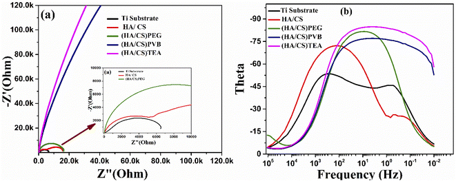 | ||
| Fig. 10 (a) Nyquist plot curves and (b) bode plot curves of the uncoated and coated Ti with HA/CS using (PEG, PVB, and TEA) as dispersing agents. | ||
Consequently, PEG and PVB polymers proved to be more corrosion resistant than TEA. The barrier properties have been improved in the current case due to the size of the CS/HA. It has been proven that nano-scale additives improve polymer barrier properties by a factor of 10 or even higher for the diffusion of solvents and gases.109 The results revealed that the corrosion ion erosion matrix rate had been reduced more effectively. Coating methods may interact with dispersants in the composite coating to create a good protective barrier.110 The results of the potentiodynamic polarization and impedance studies confirm that the Ti coated with HA/CS and additives are highly corrosion resistant.
4 Conclusions
The CS and HA nanocomposite coatings (based on polymer as additives) can be used to develop biomedical implants. The EPD enabled the coating of Ti chips with an anti-corrosion thin film of nano-HA/CS and polymers such as PVB, PEG, and TEA. These agents improved the coating process of the Ti substrate due to increasing the suspension homogeneity during the deposition and forming highly uniform layers of the composite on the top layer of Ti substrates. In addition, these additives improved the coating process leading to the high corrosion resistance of the coated Ti substrate. Electrochemical investigations, including potentiodynamic polarization (PDP), open circuit potential (OCP) measurements, and electrochemical impedance spectroscopic studies (EIS), demonstrated that the acquired layers gave corrosion protection to Ti substrates. A PDP test performed under optimized conditions significantly improved the corrosion resistance of HA/CS nanocomposite with PVB that displayed a current density of 0.0153 μA cm−2. The enhancement of the corrosion resistance of Ti substrate using HA/CS nanocomposites may be due to the formation of a highly stable and adherent film on the surface. EPD can be extended for the coverage of three-dimensional (3D) and complex Ti-based materials.Conflicts of interest
The authors report no declarations of interest.Abbreviations
| Hydroxypropyl methylcellulose | (HPMC) |
| Lemon grass oil | (LGO) |
| Boron nitride nanosheet | (BNNS) |
| Strontium | (Sr) |
| Polyvinyl alcohol | (PVA) |
| Graphene oxide | (GO) |
| Polylactic acid hybrid | (PLA) |
| Hydroxypropyltrimethyl ammonium chloride | (HAC) |
Acknowledgements
The authors gratefully acknowledge the Inorganic Chemistry Department, National Research Center, Egypt, and department of Chemical engineering, Tabbin Institute for Metallurgical Studies. The authors also thank Dr HN Abdelhamid, Assiut university, for recording the calcium ion release.References
- K. Grandfield and I. Zhitomirsky, Electrophoretic deposition of composite hydroxyapatite–silica–chitosan coatings, Mater. Charact., 2008, 59, 61–67 CrossRef CAS.
- M. Saini, Y. Singh, P. Arora, V. Arora and K. Jain, Implant biomaterials: A comprehensive review, World J. Clin. Cases, 2015, 3, 52 CrossRef.
- K. Shemtov-Yona and D. Rittel, An overview of the mechanical integrity of dental implants, BioMed Res. Int., 2015, 2015, 547384 Search PubMed.
- M. Stevanovic, M. Đošić, A. Jankovic, V. Kojic, M. Vukasinovic-Sekulic, J. Stojanovic, J. Odovic, M. Crevar Sakač, K. Y. Rhee and V. Miskovic-Stankovic, Gentamicin-loaded bioactive hydroxyapatite/chitosan composite coating electrodeposited on titanium, ACS Biomater. Sci. Eng., 2018, 4, 3994–4007 CrossRef CAS PubMed.
- D. C. Rodrigues, P. Valderrama, T. G. Wilson Jr, K. Palmer, A. Thomas, S. Sridhar, A. Adapalli, M. Burbano and C. Wadhwani, Titanium corrosion mechanisms in the oral environment: a retrieval study, Materials, 2013, 6, 5258–5274 CrossRef PubMed.
- P. Mandracci, F. Mussano, P. Rivolo and S. Carossa, Surface treatments and functional coatings for biocompatibility improvement and bacterial adhesion reduction in dental implantology, Coatings, 2016, 6, 7 CrossRef.
- K. Rezwan, Q. Chen, J. J. Blaker and A. R. Boccaccini, Biodegradable and bioactive porous polymer/inorganic composite scaffolds for bone tissue engineering, Biomaterials, 2006, 27, 3413–3431 CrossRef CAS PubMed.
- M. Đošić, M. Mitrić and V. Mišković-Stanković, The porosity and roughness of electrodeposited calcium phosphate coatings in simulated body fluid, J. Serb. Chem. Soc., 2015, 80, 237–251 CrossRef.
- R. E. McMahon, L. Wang, R. Skoracki and A. B. Mathur, Development of nanomaterials for bone repair and regeneration, J. Biomed. Mater. Res., Part B, 2013, 101, 387–397 CrossRef.
- R. C. F. Cheung, T. B. Ng, J. H. Wong and W. Y. Chan, Chitosan: an update on potential biomedical and pharmaceutical applications, Mar. Drugs, 2015, 13, 5156–5186 CrossRef CAS PubMed.
- D. W. Lee, H. Lim, H. N. Chong and W. S. Shim, Advances in chitosan material and its hybrid derivatives: a review, Open Biomater. J., 2009, 1, 10–20 CrossRef CAS.
- D. Zhitomirsky, J. Roether, A. Boccaccini and I. Zhitomirsky, Electrophoretic deposition of bioactive glass/polymer composite coatings with and without HA nanoparticle inclusions for biomedical applications, J. Mater. Process. Technol., 2009, 209, 1853–1860 CrossRef CAS.
- A. Boccaccini, S. Keim, R. Ma, Y. Li and I. Zhitomirsky, Electrophoretic deposition of biomaterials, J. R. Soc., Interface, 2010, 7, S581–S613 CrossRef CAS PubMed.
- S. Mann, Molecular tectonics in biomineralization and biomimetic materials chemistry, Nature, 1993, 365, 499–505 CrossRef CAS.
- W. Pompe, H. Worch, M. Epple, W. Friess, M. Gelinsky, P. Greil, U. Hempel, D. Scharnweber and K. Schulte, Functionally graded materials for biomedical applications, J. Mater. Sci. Eng. A, 2003, 362, 40–60 CrossRef.
- K. Yamauchi, T. Goda, N. Takeuchi, H. Einaga and T. Tanabe, Preparation of collagen/calcium phosphate multilayer sheet using enzymatic mineralization, Biomaterials, 2004, 25, 5481–5489 CrossRef CAS PubMed.
- H. Guo, K. A. Khor, Y. C. Boey and X. Miao, Laminated and functionally graded hydroxyapatite/yttria stabilized tetragonal zirconia composites fabricated by spark plasma sintering, Biomaterials, 2003, 24, 667–675 CrossRef CAS PubMed.
- K. Suzuki, T. Yumura, M. Mizuguchi, T. Taguchi, K. Sato, J. Tanaka and M. Akashi, Apatite-silica gel composite materials prepared by a new alternate soaking process, J. Sol-Gel Sci. Technol., 2001, 21, 55–63 CrossRef CAS.
- K. Furuichi, Y. Oaki, H. Ichimiya, J. Komotori and H. Imai, Preparation of hierarchically organized calcium phosphate–organic polymer composites by calcification of hydrogel, Sci. Technol. Adv. Mater., 2006, 7, 219 CrossRef CAS.
- M. Đošić, S. Eraković, A. Janković, M. Vukašinović-Sekulić, I. Z. Matić, J. Stojanović, K. Y. Rhee, V. Mišković-Stanković and S.-J. Park, In vitro investigation of electrophoretically deposited bioactive hydroxyapatite/chitosan coatings reinforced by graphene, J. Ind. Eng. Chem., 2017, 47, 336–347 CrossRef.
- D. Jugowiec, A. Łukaszczyk, Ł. Cieniek, K. Kowalski, Ł. Rumian, K. Pietryga, M. Kot, E. Pamuła and T. Moskalewicz, Influence of the electrophoretic deposition route on the microstructure and properties of nano-hydroxyapatite/chitosan coatings on the Ti-13Nb-13Zr alloy, Surf. Coat. Technol., 2017, 324, 64–79 CrossRef CAS.
- S. Bakhshandeh and S. A. Yavari, Electrophoretic deposition: a versatile tool against biomaterial associated infections, J. Mater. Chem. B, 2018, 6, 1128–1148 RSC.
- O. Geuli, N. Metoki, T. Zada, M. Reches, N. Eliaz and D. Mandler, Synthesis, coating, and drug-release of hydroxyapatite nanoparticles loaded with antibiotics, J. Mater. Chem. B, 2017, 5, 7819–7830 RSC.
- K. D. Patel, R. K. Singh, E.-J. Lee, C.-M. Han, J.-E. Won, J. C. Knowles and H.-W. Kim, Tailoring solubility and drug release from electrophoretic deposited chitosan–gelatin films on titanium, Surf. Coat. Technol., 2014, 242, 232–236 CrossRef CAS.
- J. Song, Q. Chen, Y. Zhang, M. Diba, E. Kolwijck, J. Shao, J. A. Jansen, F. Yang, A. R. Boccaccini and S. C. Leeuwenburgh, Electrophoretic deposition of chitosan coatings modified with gelatin nanospheres to tune the release of antibiotics, ACS Appl. Mater. Interfaces, 2016, 8, 13785–13792 CrossRef CAS PubMed.
- Z. Zhang, Y. Qu, X. Li, S. Zhang, Q. Wei, Y. Shi and L. Chen, Electrophoretic deposition of tetracycline modified silk fibroin coatings for functionalization of titanium surfaces, Appl. Surf. Sci., 2014, 303, 255–262 CrossRef CAS.
- C. Han, Y. Yao, X. Cheng, J. Luo, P. Luo, Q. Wang, F. Yang, Q. Wei and Z. Zhang, Electrophoretic deposition of gentamicin-loaded silk fibroin coatings on 3D-printed porous cobalt–chromium–molybdenum bone substitutes to prevent orthopedic implant infections, Biomacromolecules, 2017, 18, 3776–3787 CrossRef CAS PubMed.
- F. Pishbin, V. Mouriño, S. Flor, S. Kreppel, V. Salih, M. P. Ryan and A. R. Boccaccini, Electrophoretic deposition of gentamicin-loaded bioactive glass/chitosan composite coatings for orthopaedic implants, ACS Appl. Mater. Interfaces, 2014, 6, 8796–8806 CrossRef CAS PubMed.
- S. J. Kalita, A. Bhardwaj and H. A. Bhatt, Nanocrystalline calcium phosphate ceramics in biomedical engineering, Mater. Sci. Eng. C, 2007, 27, 441–449 CrossRef CAS.
- P. Kumar, B. S. Dehiya and A. Sindhu, Bioceramics for hard tissue engineering applications: A review, Int. J. Appl. Eng. Res, 2018, 13, 2744–2752 Search PubMed.
- L. L. Hench, An introduction to bioceramics, World scientific, 1993 Search PubMed.
- A. Harabi and E. Harabi, A modified milling system, using a bimodal distribution of highly resistant ceramics. Part 1. A natural hydroxyapatite study, Mater. Sci. Eng. C, 2015, 51, 206–215 CrossRef CAS PubMed.
- J. Almodovar, D. Castilla-Casadiego and H. Ramos-Avilez, Polysaccharide-based biomaterials for cell–material interface, Celland Material Interface, 2015, p. 215 Search PubMed.
- H. R. Avilez, D. C. Casadiego, A. V. Avila, O. P. Perez and J. Almodovar.Production of chitosan coatings on metal and ceramic biomaterials, Chitosan Based Biomaterials, Elsevier, 2017, vol. 1, pp. 255–293 Search PubMed.
- S. Yen and C. Lin, Cathodic reactions of electrolytic hydroxyapatite coating on pure titanium, Mater. Chem. Phys., 2003, 77, 70–76 CrossRef CAS.
- J.-S. Chen, H.-Y. Juang and M.-H. Hon, Calcium phosphate coating on titanium substrate by a modified electrocrystallization process, J. Mater. Sci.: Mater. Med., 1998, 9, 297–300 CrossRef CAS PubMed.
- P. áVishnu Kamath, Novel electrosynthetic route to calcium phosphate coatings, J. Mater. Chem., 1998, 8, 405–408 RSC.
- P. Ducheyne, W. Van Raemdonck, J. Heughebaert and M. Heughebaert, Structural analysis of hydroxyapatite coatings on titanium, Biomaterials, 1986, 7, 97–103 CrossRef CAS.
- P. Ducheyne, S. Radin, M. Heughebaert and J. Heughebaert, Calcium phosphate ceramic coatings on porous titanium: effect of structure and composition on electrophoretic deposition, vacuum sintering and in vitro dissolution, Biomaterials, 1990, 11, 244–254 CrossRef CAS.
- C. Kim and P. Ducheyne, Compositional variations in the surface and interface of calcium phosphate ceramic coatings on Ti and Ti-6Al-4V due to sintering and immersion, Biomaterials, 1991, 12, 461–469 CrossRef CAS PubMed.
- Y. Usui, K. Aoki, N. Narita, N. Murakami, I. Nakamura, K. Nakamura, N. Ishigaki, H. Yamazaki, H. Horiuchi and H. Kato, Carbon nanotubes with high bone-tissue compatibility and bone-formation acceleration effects, Small, 2008, 4, 240–246 CrossRef CAS PubMed.
- X. Pang and I. Zhitomirsky, Electrodeposition of composite hydroxyapatite–chitosan films, Mater. Chem. Phys., 2005, 94, 245–251 CrossRef CAS.
- H. N. Abdelhamid and H.-F. Wu, Probing the interactions of chitosan capped CdS quantum dots with pathogenic bacteria and their biosensing application, J. Mater. Chem. B, 2013, 1, 6094–6106 RSC.
- J. Gopal, H. N. Abdelhamid, P.-Y. Hua and H.-F. Wu, Chitosan nanomagnets for effective extraction and sensitive mass spectrometric detection of pathogenic bacterial endotoxin from human urine, J. Mater. Chem. B, 2013, 1, 2463–2475 RSC.
- H. Abdelhamid, Y. Lin and H.-F. Wu, Thymine chitosan nanomagnets for specific preconcentration of mercury (II) prior to analysis using SELDI-MS, Microchim. Acta, 2017, 184 Search PubMed.
- H. N. Abdelhamid and H.-F. Wu, Selective biosensing of Staphylococcus aureus using chitosan quantum dots, Spectrochim. Acta, Part A, 2018, 188, 50–56 CrossRef CAS.
- M. Dowaidar, H. Nasser Abdelhamid, M. Hällbrink, Ü. Langel and X. Zou, Chitosan enhances gene delivery of oligonucleotide complexes with magnetic nanoparticles–cell-penetrating peptide, J. Biomater. Appl., 2018, 33, 392–401 CrossRef CAS.
- H. N. Abdelhamid, H. M. El-Bery, A. A. Metwally, M. Elshazly and R. M. Hathout, Synthesis of CdS-modified chitosan quantum dots for the drug delivery of Sesamol, Carbohydr. Polym., 2019, 214, 90–99 CrossRef CAS PubMed.
- H. N. Abdelhamid and G. Badr, Nanobiotechnology as a platform for the diagnosis of COVID-19: a review, Nanotechnol. Environ. Eng., 2021, 6, 1–26 CrossRef.
- H. N. Abdelhamid, M. Dowaidar and Ü. Langel, Carbonized chitosan encapsulated hierarchical porous zeolitic imidazolate frameworks nanoparticles for gene delivery, Microporous Mesoporous Mater., 2020, 302, 110200 CrossRef CAS.
- D. Arcos and M. Vallet-Regí, Substituted hydroxyapatite coatings of bone implants, J. Mater. Chem. B, 2020, 8, 1781–1800 RSC.
- G. Choi, A. H. Choi, L. A. Evans, S. Akyol and B. Ben-Nissan, A review: Recent advances in sol-gel-derived hydroxyapatite nanocoatings for clinical applications, J. Am. Ceram. Soc., 2020, 103, 5442–5453 CrossRef CAS.
- S. Pai, M. S. Kini and R. Selvaraj, A review on adsorptive removal of dyes from wastewater by hydroxyapatite nanocomposites, Environ. Sci. Pollut. Res., 2021, 28, 11835–11849 CrossRef CAS.
- A. Jaafar, C. Hecker, P. Árki and Y. Joseph, Sol-gel derived hydroxyapatite coatings for titanium implants: A review, Bioengineering, 2020, 7, 127 CrossRef CAS.
- M. Ibrahim, M. Labaki, J.-M. Giraudon and J.-F. Lamonier, Hydroxyapatite, a multifunctional material for air, water and soil pollution control: A review, J. Hazard. Mater., 2020, 383, 121139 CrossRef CAS.
- J. Redepenning, G. Venkataraman, J. Chen and N. Stafford, Electrochemical preparation of chitosan/hydroxyapatite composite coatings on titanium substrates, J. Biomed. Mater. Res., Part A, 2003, 66, 411–416 CrossRef.
- B. Li, X. Xia, M. Guo, Y. Jiang, Y. Li, Z. Zhang, S. Liu, H. Li, C. Liang and H. Wang, Biological and antibacterial properties of the micro-nanostructured hydroxyapatite/chitosan coating on titanium, Sci. Rep., 2019, 9, 1–10 CrossRef PubMed.
- Y. Shi, M. Li, Q. Liu, Z. Jia, X. Xu, Y. Cheng and Y. Zheng, Electrophoretic deposition of graphene oxide reinforced chitosan–hydroxyapatite nanocomposite coatings on Ti substrate, J. Mater. Sci.: Mater. Med., 2016, 27, 48 CrossRef CAS PubMed.
- M. E. El-Naggar, A. Elmushyakhi, A. G. Al-Sehemi, A. Kalam, H. Algarni, S. R. Salem and M. Abou Taleb, Biomedical domains of the as-prepared nanocomposite based on hydroxyapatite, bismuth trioxide and graphene oxide, J. Mater. Res. Technol., 2022, 19, 3954–3965 CrossRef CAS.
- L. Qi, Z. Xu, X. Jiang, C. Hu and X. Zou, Preparation and antibacterial activity of chitosan nanoparticles, Carbohydr. Res., 2004, 339, 2693–2700 CrossRef CAS PubMed.
- H. N. Abdelhamid and H.-F. Wu, Multifunctional graphene magnetic nanosheet decorated with chitosan for highly sensitive detection of pathogenic bacteria, J. Mater. Chem. B, 2013, 1, 3950–3961 RSC.
- B. Cengiz, Y. Gokce, N. Yildiz, Z. Aktas and A. Calimli, Synthesis and characterization of hydroxyapatite nanoparticles, Colloids Surf., A, 2008, 322, 29–33 CrossRef CAS.
- K.-W. Kim, E.-H. Lee, J.-S. Kim, K.-H. Shin and K.-H. Kim, Effect of an etching Ti substrate on a catalytic oxide electrode, J. Electrochem. Soc., 2001, 148, B111 CrossRef CAS.
- O. Zinger, G. Zhao, Z. Schwartz, J. Simpson, M. Wieland, D. Landolt and B. Boyan, Differential regulation of osteoblasts by substrate microstructural features, Biomaterials, 2005, 26, 1837–1847 CrossRef CAS.
- S. L. Esfahani, S. Rouhani and Z. Ranjbar, Optimization the electrophoretic deposition fabrication of graphene-based electrode to consider electro-optical applications, Surf. Interfaces, 2017, 9, 218–227 CrossRef CAS.
- A. N. Jasim, M. khethier Abbass, M. Jasim and K. Salah, Synthesis, Characterization and Optimization of Electrophoretic Deposition (EPD) Parameters of YSZ Layer on Ti-6Al-4V Alloy substrate, IOP Conference Series: Materials Science and Engineering, IOP Publishing, 2020, p. 012082 Search PubMed.
- M. Choudhury, S. R. Ahmed, M. M. I. Tusher, M. A. Uddin, M. S. Alam and T. Soga, International Conference on Innovations in Science, Engineering and Technology (ICISET), IEEE, 2018, pp. 294–298.Optimization of Electrophoretic Deposition Parameters for Uniform Titanium Oxide Deposition on Conductive Glass Substrate Search PubMed.
- H. M. El-Bery and H. N. Abdelhamid, Photocatalytic Hydrogen Generation via Water Splitting using ZIF-67 derived Co3O4@ C/TiO2, J. Environ. Chem. Eng., 2021, 105702 CrossRef CAS.
- W. D. Pyrz and D. J. Buttrey, Particle size determination using TEM: a discussion of image acquisition and analysis for the novice microscopist, Langmuir, 2008, 24, 11350–11360 CrossRef CAS PubMed.
- E. Smirnov, Assemblies of gold nanoparticles at liquid-liquid interfaces, EPFL, 2017 Search PubMed.
- S. Bhattacharjee, DLS and zeta potential–what they are and what they are not?, J. Controlled Release, 2016, 235, 337–351 CrossRef CAS PubMed.
- A. A. Zaman and S. Mathur, Influence of dispersing agents and solution conditions on the solubility of crude kaolin, J. Colloid Interface Sci., 2004, 271, 124–130 CrossRef CAS PubMed.
- Y. Chevalier, S. Brunel, P. Le Perchec, M. Mosquet and J.-P. Guicquero, Polyoxyethylene di-phosphonates as dispersing agents, Trends in Colloid and Interface Science, 1997, XI, pp. 6–10 Search PubMed.
- I. Zhitomirsky, Cathodic electrodeposition of ceramic and organoceramic materials. Fundamental aspects, Adv. Colloid Interface Sci., 2002, 97, 279–317 CrossRef CAS.
- I. Zhitomirsky and A. Petric, Electrophoretic deposition of electrolyte materials for solid oxide fuel cells, J. Mater. Sci., 2004, 39, 825–831 CrossRef CAS.
- K. Mittal, Adhesion measurement of thin films, Electrocomponent Sci. Technol., 1976, 3, 21–42 CrossRef CAS.
- B. Chapman, Thin-film adhesion, J. Vac. Sci. Technol., 1974, 11, 106–113 CrossRef CAS.
- E.-S. M. El-Sayed, A. Omar, M. Ibrahim and W. I. Abdel-Fattah, On the structural analysis and electronic properties of chitosan/hydroxyapatite interaction, J. Comput. Theor. Nanosci., 2009, 6, 1663–1669 CrossRef CAS.
- M. Ibrahim, W. I. Abdel-Fattah, E.-S. M. El-Sayed and A. Omar, A novel model for Chitosan/Hydroxyapatite Interaction, Quantum Matter, 2013, 2, 234–237 CrossRef CAS.
- S. Sudhamani, M. Prasad and K. U. Sankar, DSC and FTIR studies on gellan and polyvinyl alcohol (PVA) blend films, Food Hydrocolloids, 2003, 17, 245–250 CrossRef CAS.
- J. Kumar and S. D'Souza, Preparation of PVA membrane for immobilization of GOD for glucose biosensor, Talanta, 2008, 75, 183–188 CrossRef CAS PubMed.
- E. M. Reis, W. L. Vasconcelos, H. S. Mansur and M. Pereira, Synthesis and characterization of silica-chitosan porous hybrids for tissue engineering, Key Engineering Materials, Trans Tech Publ, 2008, pp. 967–970 Search PubMed.
- Q. Chen, H. Hu and J. Xu, Authenticating top-k queries in location-based services with confidentiality, Proceedings of the VLDB Endowment, 2013, 7, 49–60 CrossRef.
- P. Sarkar and P. S. Nicholson, Electrophoretic deposition (EPD): mechanisms, kinetics, and application to ceramics, J. Am. Ceram. Soc., 1996, 79, 1987–2002 CrossRef CAS.
- P. Kujawa, P. Moraille, J. Sanchez, A. Badia and F. M. Winnik, Effect of molecular weight on the exponential growth and morphology of hyaluronan/chitosan multilayers: A surface plasmon resonance spectroscopy and atomic force microscopy investigation, J. Am. Chem. Soc., 2005, 127, 9224–9234 CrossRef CAS.
- N. Farnoosh, K. Adamiak and G. Castle, 3-D numerical analysis of EHD turbulent flow and mono-disperse charged particle transport and collection in a wire-plate ESP, J. Electrost., 2010, 68, 513–522 CrossRef CAS.
- Z. Long and Q. Yao, Evaluation of various particle charging models for simulating particle dynamics in electrostatic precipitators, J. Aerosol Sci., 2010, 41, 702–718 CrossRef CAS.
- S. Arif, D. Branken, R. Everson, H. Neomagus, L. Le Grange and A. Arif, CFD modeling of particle charging and collection in electrostatic precipitators, J. Electrost., 2016, 84, 10–22 CrossRef CAS.
- H. Potente, K. Kretschmer and J. Flecke, A physical-mathematical model for the dispersion process in continuous mixers, Polym. Eng. Sci., 2002, 42, 19–32 CrossRef CAS.
- A. Scurati, D. Feke and I. Manas-Zloczower, Analysis of the kinetics of agglomerate erosion in simple shear flows, Chem. Eng. Sci., 2005, 60, 6564–6573 CrossRef CAS.
- S. Hansen, D. Khakhar and J. M. Ottino, Dispersion of solids in nonhomogeneous viscous flows, Chem. Eng. Sci., 1998, 53, 1803–1817 CrossRef CAS.
- K. Ke, Y. Wang, X.-Q. Liu, J. Cao, Y. Luo, W. Yang, B.-H. Xie and M.-B. Yang, A comparison of melt and solution mixing on the dispersion of carbon nanotubes in a poly (vinylidene fluoride) matrix, Composites, Part B, 2012, 43, 1425–1432 CrossRef CAS.
- S. He, J. Zhang, X. Xiao, Y. Lai, A. Chen and Z. Zhang, Study on the morphology development and dispersion mechanism of polypropylene/graphene nanoplatelets composites for different shear field, Compos. Sci. Technol., 2017, 153, 209–221 CrossRef CAS.
- Y. M. Harshe and M. Lattuada, Breakage rate of colloidal aggregates in shear flow through Stokesian dynamics, Langmuir, 2012, 28, 283–292 CrossRef CAS PubMed.
- O. E. Philippova, E. V. Volkov, N. L. Sitnikova, A. R. Khokhlov, J. Desbrieres and M. Rinaudo, Two types of hydrophobic aggregates in aqueous solutions of chitosan and its hydrophobic derivative, Biomacromolecules, 2001, 2, 483–490 CrossRef CAS PubMed.
- S. Asakura and F. Oosawa, Interaction between particles suspended in solutions of macromolecules, J. Polym. Sci., 1958, 33, 183–192 CrossRef CAS.
- X. Zhang, Z. H. Jiang, Z. P. Yao, Y. Song and Z. D. Wu, Effects of scan rate on the potentiodynamic polarization curve obtained to determine the Tafel slopes and corrosion current density, Corros. Sci., 2009, 51, 581–587 CrossRef CAS.
- E. Vafa, R. Bazargan-Lari and M. E. Bahrololoom, Electrophoretic deposition of polyvinyl alcohol/natural chitosan/bioactive glass composite coatings on 316L stainless steel for biomedical application, Prog. Org. Coat., 2021, 151, 106059 CrossRef CAS.
- T. Bellezze, G. Giuliani and G. Roventi, Study of stainless steels corrosion in a strong acid mixture. Part 1: cyclic potentiodynamic polarization curves examined by means of an analytical method, Corros. Sci., 2018, 130, 113–125 CrossRef CAS.
- T. Bellezze, G. Giuliani, A. Viceré and G. Roventi, Study of stainless steels corrosion in a strong acid mixture. Part 2: anodic selective dissolution, weight loss and electrochemical impedance spectroscopy tests, Corros. Sci., 2018, 130, 12–21 CrossRef CAS.
- P. RAJA, A. RAHIM, H. Osman and K. Awang, Inhibitory Effect of Kopsia Singapurensis Extract on the Corrosion Behavior ofMild Steel in AcidMedia, Acta Phys.-Chim. Sin., 2010, 26, 2171–2176 CAS.
- V. Oliveira, C. Aguiar, A. Vazquez, A. Robin and M. Barboza, Improving corrosion resistance of Ti–6Al–4V alloy through plasma-assisted PVD deposited nitride coatings, Corros. Sci., 2014, 88, 317–327 CrossRef CAS.
- A. Attia and H. Abdel-Fatah, Triton X-100 as a Non-Ionic surfactant for corrosion inhibition of mild steel during acid cleaning, Met. Mater. Int., 2020, 26, 1715–1724 CrossRef CAS.
- M. Djošić, V. Panić, J. Stojanović, M. Mitrić and V. B. Mišković-Stanković, The effect of applied current density on the surface morphology of deposited calcium phosphate coatings on titanium, Colloids Surf., A, 2012, 400, 36–43 CrossRef.
- S. Mahmoodi, L. Sorkhi, M. Farrokhi-Rad and T. Shahrabi, Electrophoretic deposition of hydroxyapatite–chitosan nanocomposite coatings in different alcohols, Surf. Coat. Technol., 2013, 216, 106–114 CrossRef CAS.
- F. E. Baştan, M. A. U. Rehman, Y. Y. Avcu, E. Avcu, F. Üstel and A. R. Boccaccini, Electrophoretic co-deposition of PEEK-hydroxyapatite composite coatings for biomedical applications, Colloids Surf., B, 2018, 169, 176–182 CrossRef.
- D. Annur, F. Bayu, S. Supriadi and B. Suharno, Electrophoretic Deposition of Hydroxyapatite/Chitosan Coating on Porous Titanium for Orthopedic Application, 2022 Search PubMed.
- O. Ø. Knudsen and A. Forsgren, Corrosion control through organic coatings, CRC Press, 2017 Search PubMed.
- Q. Sun, F. J. Schork and Y. Deng, Water-based polymer/clay nanocomposite suspension for improving water and moisture barrier in coating, Compos. Sci. Technol., 2007, 67, 1823–1829 CrossRef CAS.
- S. Radhakrishnan, C. Siju, D. Mahanta, S. Patil and G. Madras, Conducting polyaniline–nano-TiO2 composites for smart corrosion resistant coatings, Electrochim. Acta, 2009, 54, 1249–1254 CrossRef CAS.
- Y. Lei, J.-J. Guan, W. Chen, Q.-F. Ke, C.-Q. Zhang and Y.-P. Guo, Fabrication of hydroxyapatite/chitosan porous materials for Pb (II) removal from aqueous solution, RSC Adv., 2015, 5, 25462–25470 RSC.
- H.-C. Hsu, Y.-C. Chung, S.-C. Wu, Y.-C. Ho, H.-H. Chang and W.-F. Ho, Preparation of chitosan/hydroxyapatite composite coating obtained from crab shells on hierarchical micro/nano-textured Ti surface, Surf. Coat. Technol., 2022, 437, 128364 CrossRef CAS.
- H. U. Ali, D. N. Iqbal, M. Iqbal, S. Ezzine, A. Arshad, R. Zeeshan, A. A. Chaudhry, S. Z. Alshawwa, A. Nazir and A. F. Khan, HPMC crosslinked chitosan/hydroxyapatite scaffolds containing Lemongrass oil for potential bone tissue engineering applications, Arabian J. Chem., 2022, 15, 103850 CrossRef CAS.
- W. Huang, D. Mei, H. Qin, J. Li, L. Wang, X. Ma, S. Zhu and S. Guan, Electrophoretic deposited boron nitride nanosheets-containing chitosan-based coating on Mg alloy for better corrosion resistance, biocompatibility and antibacterial properties, Colloids Surf., A, 2022, 638, 128303 CrossRef CAS.
- B.-D. Hahn, D.-S. Park, J.-J. Choi, J. Ryu, W.-H. Yoon, J.-H. Choi, H.-E. Kim and S.-G. Kim, Aerosol deposition of hydroxyapatite–chitosan composite coatings on biodegradable magnesium alloy, Surf. Coat. Technol., 2011, 205, 3112–3118 CrossRef CAS.
- S. Bagheri-Khoulenjani, H. Mirzadeh, M. Etrati-Khosroshahi and M. Ali Shokrgozar, Particle size modeling and morphology study of chitosan/gelatin/nanohydroxyapatite nanocomposite microspheres for bone tissue engineering, J. Biomed. Mater. Res., Part A, 2013, 101, 1758–1767 CrossRef PubMed.
- V. Murugesan, M. Vaiyapuri and A. Murugeasan, Fabrication and characterization of strontium substituted chitosan modify hydroxyapatite for biomedical applications, Inorg. Chem. Commun., 2022, 142, 109653 CrossRef CAS.
- J. Prakash, D. Prema, K. Venkataprasanna, K. Balagangadharan, N. Selvamurugan and G. D. Venkatasubbu, Nanocomposite chitosan film containing graphene oxide/hydroxyapatite/gold for bone tissue engineering, Int. J. Biol. Macromol., 2020, 154, 62–71 CrossRef CAS PubMed.
- J. Jin, X. Chen and S. Zhou, Biocorrosion evaluation and bonding strength of HA-CS/PLA hybrid coating on micro-arc oxidised AZ91D magnesium alloy, Materials Technology, 2022, 37, 503–510 CrossRef CAS.
- M. Tian, S. Cai, L. Ling, Y. Zuo, Z. Wang, P. Liu, X. Bao and G. Xu, Superhydrophilic hydroxyapatite/hydroxypropyltrimethyl ammonium chloride chitosan composite coating for enhancing the antibacterial and corrosion resistance of magnesium alloy, Prog. Org. Coat., 2022, 165, 106745 CrossRef CAS.
| This journal is © The Royal Society of Chemistry 2022 |

