 Open Access Article
Preparation of modified MFI-type/PDMS composite membranes for the separation of dichlorobenzene isomers via pervaporation
Qiu-Ping Heab,
Ying-Ying Wang *bc,
Peng-Fei Wang*bc and
Xiao-Ming Dou*a
aInstitute of Photonics & Bio-medicine, School of Science, East China University of Science and Technology, Shanghai 200062, China. E-mail: tech@sh-lq.com; xmdou@ecust.edu.cn
bShanghai Luqiang New Materials Co., Ltd, Shanghai 200062, China. E-mail: 1032629005@qq.com; wpf@sh-lq.com; Tel: +86-21-69577696
cState Key Laboratory of Polyolefin Catalytic Technology and High Performance Material, Shanghai Research Institute of Chemical Industry Co., Ltd, Shanghai 200062, China
First published on 30th May 2022
Abstract
Zeolite–polymer composite membranes have become promising and effective materials for the pervaporative separation of liquids, especially for isomeric mixtures. In this paper, silicalite-1/PDMS composite membranes have been used to investigate the separation of dichlorobenzene (DCB) isomers via pervaporation for the first time. Silicalite-1 zeolites modified by the silane coupling agent, NH3–C3H6–Si(OC2H5)3, have been incorporated into polydimethylsiloxane (PDMS). Then, the silicalite-1/PDMS composite membranes have been successfully prepared on porous polyvinylidene fluoride (PVDF) supports. The morphology and structure of the silicalite-1 zeolites and silicalite-1/PDMS composite membranes have been characterized by XRD, FTIR, SEM and BET techniques. The results show that the modified silicalite-1 zeolite particles have smaller pore sizes dispersed more uniformly in the active layers of the silicalite-1/PDMS composite membranes and present fewer aggregation and pinholes formed by the accumulation of zeolite particles. The silicalite-1/PDMS composite membranes are all dense and continuous with good homogeneity. To evaluate the pervaporative separation performance of the DCB isomers, the unmodified and modified silicalite-1/PDMS composite membranes have been further tested in single-isomer and binary-isomer systems at 60 °C. The modified silicalite-1/PDMS composite membranes present higher DCB isomer separation factors. The separation factors of the modified silicalite-1/PDMS composite membranes in the binary-isomer systems for p-/o-DCB and p-/m-DCB are 3.53 and 5.63, respectively. The permeate flux of p-DCB through the modified silicalite-1/PDMS composite membranes in the p-/o-DCB binary-isomer system is 116.7 g m−2 h−1 and in the p-/m-DCB binary-isomer system, it is 93.5 g m−2 h−1. The result provides a new approach towards the pervaporative separation of DCB isomers from their mixture for future industrialization applications.
1. Introduction
Dichlorobenzene (DCB) isomers are important fine chemical raw materials widely used in medicine, pesticides, solvents, deodorants and other fields. DCBs are produced by the chlorination of benzene or mono-chlorobenzene, which usually produces a mixture of three DCB isomers: p-dichlorobenzene (p-DCB), o-dichlorobenzene (o-DCB), and m-dichlorobenzene (m-DCB). Due to the similar physical and chemical properties of the DCB isomers, the differences in their boiling points (o-DCB: 180.4 °C, m-DCB: 173 °C and p-DCB: 174.1 °C) and their relative volatility (1.059) are very small. Thus, it is difficult to separate them by traditional distillation and crystallization methods, which have high energy consumption and low efficiency.1–6 The low purity of individual DCB limits its industrial applications and seriously restricts the production of upstream and downstream products. Therefore, it is extremely important to find a new separation method to obtain DCB isomers with higher purity.There are many reports on the separation of DCB isomers by the zeolite adsorption mechanism. The US patent7 adopts KX zeolites to separate m-DCB. The JP patents8 use FAU zeolites to separate DCB isomers. Li et al.9 investigated the separation of the p-DCB and o-DCB isomers by X and Y zeolites modified by ion exchange. Lin et al.10 studied the separation of the p-DCB and o-DCB isomers by ZSM-5 zeolites modified by ion exchange. Sun et al.11 used silicalite-1 zeolites to separate the m-DCB isomer. The US patent12 utilized zeolite TPZ-3 to separate the DCB isomers. Among the above zeolites, the most popular zeolites are MFI-type zeolites (pore dimensions: 0.53 × 0.56 nm and 0.51 × 0.57 nm).13,14 According to kinetic theory, the DCB isomers can be separated well through MFI-type zeolites. The molecular sizes of the DCB isomers (kinetic diameter: p-DCB, 0.58 nm; o-DCB and m-DCB, 0.68 nm) are similar to the pore size of MFI-type zeolites.15 Each DCB isomer has different chemical affinities and adsorption properties with the MFI-type zeolite pores, which was proved by Guo and Long.16 However, the disadvantages of the high thermal effect, difficult zeolite regeneration, huge zeolite dosage and complex solid waste treatment limit the development of zeolite adsorption methods in DCB isomer separation (also granular silicalite-1 zeolite adsorbents). Compared with granular zeolite adsorbents, zeolite membranes possess more obvious advantages, such as low mass transfer resistance, low energy consumption, high zeolite utilization and high efficiency. MFI-type zeolite inorganic membranes (silicalite-1/Al2O3 membrane) have been successfully prepared and applied to the pervaporative separation of DCB isomers in our previous work. The results demonstrate that silicalite-1/Al2O3 membranes exhibit good separation properties.15 Unfortunately, the large-scale preparation of silicalite-1/Al2O3 membranes in the industry is still a great technical challenge, which hinders its future industrial applications. Hence, finding new materials for the separation of DCB isomers is extremely urgent.
Nowadays, inorganic–polymer composite materials have been a popular choice in the fields of energy storage,17–21 aircraft industry,22 building industry,23 sensors,24–26 enantiomeric separation of molecules or drugs27–29 and membrane-based separation.30–32 Since inorganic–polymer composite materials have the potential to combine the high surface area, rich pore structure, excellent mechanical capacity and shape-selective properties of inorganic materials with the low-price, flexibility and processability of polymer materials, inorganic–polymer composite membranes are the most promising and effective composite materials with low energy consumption and high efficiency for membrane-based separation, especially for isomeric, thermosensitive or azeotropic liquid mixtures33–38 such as DCB isomers.
Owing to the reduced internal tension and the flexible molecular chain, polydimethylsiloxane (PDMS) membranes exhibit high permeability and good compatibility with a variety of solvents, which makes PDMS the most common type of polymer membrane used in membrane-based separation.39–45 Zeolites are the most used inorganic fillers because of their extraordinary structure with rich pores and excellent effects in selective separation, especially MFI-type zeolites.46–54 Notably, in the past decades, many researchers have utilized MFI-type/PDMS composite membranes for gas or liquid separation and recovery. Xue et al. prepared ZSM-5/PDMS composite membrane with different Si/Al ratios for the pervaporative recovery of butanol.55 Banihashemi et al. adopted ZSM-5/PDMS composite membranes to separate CO2 from CO2/CH4 or CO2/N2 systems.56 Ramaiah used the ZSM-5/PDMS/PVDF composite membrane to remove hazardous chlorinated VOCs from aqueous solutions.48 Li et al. recycled phenol from aqueous solutions via pervaporation with the ZSM-5/PDMS/PVDF composite membrane.57 Zhou et al. treated silicalite-1 with vinyltriethoxysilane, and the separation factor of the silicalite-1/PDMS composite membranes for the pervaporation of dilute ethanol solutions was improved.58 Han et al. reported the modification of the hydrophobicity of ZSM-5 zeolites with different silane coupling agents, and the separation performance of the modified ZSM-5/PDMS composite membranes for ethanol/water separation was improved.59 Sun et al. used mercaptopropyltrimethoxysilane to modify the surface of H-ZSM-5 zeolites. They found that the number of non-selective voids in the membrane decreases, resulting in the improvement of pervaporation performance.60 Ji et al. modified ZSM-5 zeolites with NH3–C3H6–Si(OC2H5)3 (KH-550), which improved the pervaporation performance and stability of the ZSM-5/PDMS membranes.61 Based on the above investigations, the surface modification of zeolites has proved to be useful to improve the performance of composite membranes, which can both improve the dispersion of zeolites in the PDMS matrix and the compatibility between the zeolites and PDMS matrix. It is quite conducive to fabricate MFI-type/PDMS composite membranes with excellent structural integrity. Despite the above research, there is still no report on the pervaporative separation of DCB isomers by MFI-type/PDMS composite membranes.
Herein, silane coupling agent-modified silicalite-1/PDMS composite membranes with dense and continuous active layers have been successfully fabricated by a scraping method and used to separate DCB isomers from their mixtures via pervaporation for the first time. The silicalite-1 zeolites has been modified with a silane coupling agent, NH3–C3H6–Si(OC2H5)3 (KH-550). Then, the modified silicalite-1 zeolite powders have been incorporated into the PDMS matrix to form the silicalite-1/PDMS composite membranes. The main objectives of this work are to study the influence of silicalite-1 zeolite modification on the integrity of the silicalite-1/PDMS composite membranes as well as to study their selective separation performance towards DCB isomers. The silicalite-1/PDMS composite membranes have been characterized by X-ray diffraction (XRD), scanning electron microscopy (SEM), Fourier transform infrared (FT-IR) spectroscopy and physical adsorption methods (BET). The pervaporative separation of DCB isomers in both single-isomer and binary-isomer systems has been studied. The performance of the modified silicalite-1/PDMS composite membranes has been compared with those obtained using unmodified silicalite-1/PDMS composite membranes.
2. Experimental
2.1 Materials and reagents
All the chemicals used in our experiments were of analytical grade and used without any further purification. Tetraethyl orthosilicate (TEOS, 98%), p-dichlorobenzene (99%), o-dichlorobenzene (98%), m-dichlorobenzene (99%), n-heptane (99%), and anhydrous ethanol (99.5%) were all purchased from Aladdin Chemical Reagents Co., Ltd. The hydroxyl-terminated polydimethylsiloxane (OH–PDMS) was purchased from Beijing Dingye Co. Ltd, with a kinetic viscosity of 20![[thin space (1/6-em)]](https://www.rsc.org/images/entities/char_2009.gif) 000 MPa s. Dibutyltin dilaurate (DBTOL, 95%) was purchased from Sinopharm Chemical Reagents Co., Ltd. Silicalite-1 zeolites were purchased from Nankai University Catalyst Co., Ltd. and the SEM images of the zeolites are presented in Fig. 8. Polyvinylidene fluoride (PVDF) supports (hydrophobic, diameter: 80 mm, thickness: 0.15 mm, pore size: 0.22 μm) were purchased from Hangzhou Micropai Technology Co., Ltd.
000 MPa s. Dibutyltin dilaurate (DBTOL, 95%) was purchased from Sinopharm Chemical Reagents Co., Ltd. Silicalite-1 zeolites were purchased from Nankai University Catalyst Co., Ltd. and the SEM images of the zeolites are presented in Fig. 8. Polyvinylidene fluoride (PVDF) supports (hydrophobic, diameter: 80 mm, thickness: 0.15 mm, pore size: 0.22 μm) were purchased from Hangzhou Micropai Technology Co., Ltd.
2.2 Preparation of the silicalite-1/PDMS composite membranes
![[thin space (1/6-em)]](https://www.rsc.org/images/entities/char_2009.gif) :
:![[thin space (1/6-em)]](https://www.rsc.org/images/entities/char_2009.gif) Wn-heptane = 10
Wn-heptane = 10![[thin space (1/6-em)]](https://www.rsc.org/images/entities/char_2009.gif) :
:![[thin space (1/6-em)]](https://www.rsc.org/images/entities/char_2009.gif) 85) were added to a container and stirred vigorously for 4.0 h to mix it uniformly. Secondly, 3.0 g calcined silicalite-1 zeolite powders (WPDMS
85) were added to a container and stirred vigorously for 4.0 h to mix it uniformly. Secondly, 3.0 g calcined silicalite-1 zeolite powders (WPDMS![[thin space (1/6-em)]](https://www.rsc.org/images/entities/char_2009.gif) :
:![[thin space (1/6-em)]](https://www.rsc.org/images/entities/char_2009.gif) Wzeolite = 10
Wzeolite = 10![[thin space (1/6-em)]](https://www.rsc.org/images/entities/char_2009.gif) :
:![[thin space (1/6-em)]](https://www.rsc.org/images/entities/char_2009.gif) 3) were added to the suspensions and stirred for another 1.0 h, then sonicated for 0.5 h to disperse the silicalite-1 zeolites in the PDMS solutions. Then, TEOS (WPDMS
3) were added to the suspensions and stirred for another 1.0 h, then sonicated for 0.5 h to disperse the silicalite-1 zeolites in the PDMS solutions. Then, TEOS (WPDMS![[thin space (1/6-em)]](https://www.rsc.org/images/entities/char_2009.gif) :
:![[thin space (1/6-em)]](https://www.rsc.org/images/entities/char_2009.gif) WTEOS = 10
WTEOS = 10![[thin space (1/6-em)]](https://www.rsc.org/images/entities/char_2009.gif) :
:![[thin space (1/6-em)]](https://www.rsc.org/images/entities/char_2009.gif) 1) was added as a crosslinking agent and mixed for 1.0 h. Lastly, DBTOL (WPDMS
1) was added as a crosslinking agent and mixed for 1.0 h. Lastly, DBTOL (WPDMS![[thin space (1/6-em)]](https://www.rsc.org/images/entities/char_2009.gif) :
:![[thin space (1/6-em)]](https://www.rsc.org/images/entities/char_2009.gif) WDBTOL = 10
WDBTOL = 10![[thin space (1/6-em)]](https://www.rsc.org/images/entities/char_2009.gif) :
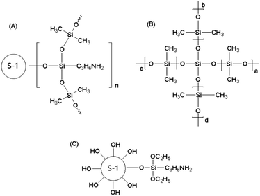
:![[thin space (1/6-em)]](https://www.rsc.org/images/entities/char_2009.gif) 0.2) was added to the mixture and agitated vigorously for 1.0–3.0 h. After ultrasonic treatment, the solutions become highly viscous without bubbles and were then immediately cast on the surfaces of the PVDF supports and scraped subsequently to form thin membranes. The prepared membranes were dried at room temperature for 12.0–24.0 h and then further crosslinked in a vacuum oven at 80 °C for 6.0 h. During this crosslinking process, two crosslinking reactions occurred. One was the ethoxy groups of the modified silicalite-1 zeolites reacting with the hydroxyl of PDMS. The other one was the ethoxy groups of the crosslinking agent TEOS reacting with the hydroxyl of PDMS. The final products of these two crosslinking reactions are presented in Fig. 1(A) and (B), respectively.
0.2) was added to the mixture and agitated vigorously for 1.0–3.0 h. After ultrasonic treatment, the solutions become highly viscous without bubbles and were then immediately cast on the surfaces of the PVDF supports and scraped subsequently to form thin membranes. The prepared membranes were dried at room temperature for 12.0–24.0 h and then further crosslinked in a vacuum oven at 80 °C for 6.0 h. During this crosslinking process, two crosslinking reactions occurred. One was the ethoxy groups of the modified silicalite-1 zeolites reacting with the hydroxyl of PDMS. The other one was the ethoxy groups of the crosslinking agent TEOS reacting with the hydroxyl of PDMS. The final products of these two crosslinking reactions are presented in Fig. 1(A) and (B), respectively.2.3 Characterization
The morphology of the silicalite-1 zeolite and the SEM images of the top view and cross-sectional view of the silicalite-1/PDMS composite membranes were captured using scanning electron microscopy (SEM, Hitachi S-4800, Cam Scan) equipped with a W-tungsten filament operated at 3 kV. The silicalite-1/PDMS composite membranes were fractured in liquid nitrogen. The crystalline structures of the silicalite-1 zeolites and silicalite-1/PDMS composite membranes were examined by X-ray diffractometry (D/max-II B, Japan) with the scanning range of 5° to 80° at a scanning rate of 6° min−1 and a step size of 0.02° using Cu Kα radiation (λ = 1.541874 Å). The BET surface areas and the nitrogen adsorption–desorption isotherms of the silicalite-1 zeolites were measured at −196 °C using a Micromeritics ASAP 2020 nitrogen adsorption analyser. The BET surface areas and the total pore volumes were determined by the Brunauer–Emmett–Teller (BET) method. The micropore area and volume were determined using the t-plot technique. The FT-IR spectra of the silicalite-1 zeolite and silicalite-1/PDMS composite membranes were recorded to study the changes during the modification and crosslinking on a Nicolet Impact 410 FTIR spectrometer equipped with a DTGS detector and using the KBr pellet technique in the range of 400–4000 cm−1.2.4 Pervaporation experiments
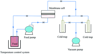
The scheme of the self-designed pervaporation apparatus is presented in Fig. 2, which includes the feed circulation, heating, membrane cell, condensation and vacuum system. The effective area of the membrane module was 19.63 cm2. The permeate side pressure was adjusted to 1000 Pa by a vacuum pump. The silicalite-1/PDMS composite membranes with a diameter of 60 mm circle were installed in the membrane cell. The temperature of the DCB feed solutions was maintained at 60 °C and the single-isomer or binary-isomer DCB feed solutions were continuously circulated from a feed tank to the membrane module using the peristaltic pump. The flow rate of the feed solutions was maintained at 100 ml min−1. On the permeate side, the DCB-isomer permeation was trapped in cold traps, condensed by liquid nitrogen (−196 °C) and analysed using a GC with an online flame ionization detector (FID). Each run of the experiment was repeated at least three times using three identical membranes and fresh feed solutions to guarantee reproducibility. The final data are the average of the three experimental readings. The experimental error in most of the data during the pervaporation of the DCB isomers in our experiments was about 3%. The separation performances of the composite membranes are evaluated based on the total flux (J) and the selective separation factor (α). The permeation total flux (J) and the selective separation factor (αp/o or αp/m) in a binary-isomer system are calculated according to the following equations:where W represents the weight of the collected permeation, A is the effective area of the membranes and t is the permeation time; yp-DCB, yo-DCB and ym-DCB represent the initial weight fractions of p-DCB, o-DCB and m-DCB in the feed, respectively; xp-DCB, xo-DCB and xm-DCB represent the weight fractions of p-DCB, o-DCB and m-DCB in the permeating streams, respectively.
3. Results and discussion
3.1 XRD analysis
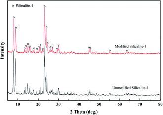
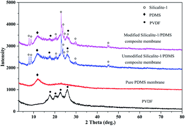
Fig. 3 shows the XRD patterns of the unmodified and modified silicalite-1 zeolites. The two samples present the characteristic peaks of MFI-type zeolite at 2θ values of 8.1°, 8.9°, 13.3°, 13.9°, 14.8°, 15.9°, 17.8°, 20.8°, 23.2°, 24.0°, 25.9°, 29.9°, 45.1° and 45.6°.58 The XRD patterns of the modified silicalite-1 zeolites maintain high peak intensity, indicating that the surface modification did not damage the crystal structure and the modified silicalite-1 zeolites still have a complete crystal structure and selective separation performance.The XRD patterns of the PVDF supports, pure PDMS membranes and silicalite-1/PDMS composite membranes on the PVDF supports are presented in Fig. 4. The characteristic peaks of the PVDF supports are detected at 2θ from 15° to 30°. A broad peak at 2θ = 10°–15° corresponding to the characteristic peaks of cross-linked PDMS is presented in Fig. 4, which is similar to the peak reported in previous literature.59 The result illustrates that the pre-polymer OH–PDMS successfully cross-linked with TEOS. With the addition of the silicalite-1 zeolite, new peaks in the modified and unmodified silicalite-1/PDMS composite membrane are found at 8.1°, 8.9°, 23.2°, 24.0°, 29.9°, 45.1° and 45.6°, which all correspond well with those of the standard silicalite-1 zeolites. Furthermore, the characteristic peaks of cross-linked PDMS at 2θ = 10°–15° and the PVDF supports at 2θ = 17.6° and 26.0° are detected in the modified and unmodified silicalite-1/PDMS composite membranes. Notably, there is no obvious difference between the XRD patterns of the modified and unmodified silicalite-1/PDMS composite membranes.
3.2 FT-IR analysis
The unmodified silicalite-1 zeolites were calcined in air at 550 °C for 5 h before modification. The FT-IR spectra of the unmodified and modified silicalite-1 zeolites are presented in Fig. 5(A) and (B), which demonstrate the occurrence of surface modification. The peaks at 1230, 1099, 804, 548 and 448 cm−1 correspond to the asymmetric stretching of Si–O–Si in the silicalite-1 zeolite framework.51,59,63 There is no obvious difference in the low-frequency regions between the unmodified and modified silicalite-1 zeolites, which proves that the characteristic vibrational modes of the silicalite-1 zeolite framework remain unchanged after surface modification. However, there are significant changes in the high-frequency regions. The broad peak near 3420 cm−1 is attributed to the hydroxyl groups.61–63 The intensity of the hydroxyl groups in the modified silicalite-1 zeolites decreases distinctly. The change in the broad peak near 3420 cm−1 indicates the reactions between the –OC2H5 of KH-550 and the –OH of the silicalite-1 zeolites, which makes the surface of the modified silicalite-1 zeolites more hydrophobic.61 Moreover, three new weak peaks around 2960, 2936 and 2874 cm−1 are detected in the modified silicalite-1 zeolites, as shown in Fig. 5(B), which indicate the stretching of –CH2 groups and the –CH model in the terminal –CH3 groups.61 The new emerging peaks in the modified silicalite-1 zeolites also indicate the formation of alkyl chains in KH-550 on the surface of the silicalite-1 zeolites. These results further indicate that the silicalite-1 zeolites are successfully modified by KH-550.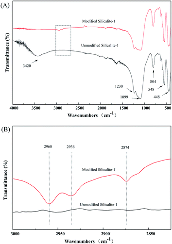 | ||
| Fig. 5 FT-IR spectra of the silicalite-1 zeolites before and after KH-550 modification. (B) The magnified segment of (A). | ||
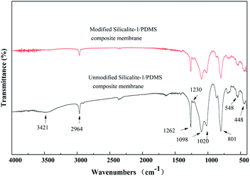
Fig. 6 shows the FT-IR spectra of the composite membranes prepared using unmodified and modified silicalite-1 zeolites. The stretching vibration of the –CH3 groups of the PDMS is observed at 2964 cm−1.59 Compared with the spectra of the silicalite-1 zeolites in Fig. 5(A) and those of the silicalite-1/PDMS composite membranes in Fig. 6, three new peaks around 1262, 1020 and 801 cm−1 appear in the silicalite-1/PDMS composite membranes. The peaks at 1262 and 801 cm−1 correspond to the deform vibration of Si–CH3.59 The adsorption peak at 1020 cm−1 has been proved to be the characteristic peak of Si–O–Si.59 The results of the analysis in Fig. 5 and 6 indicate the successful preparation of the unmodified and modified silicalite-1/PDMS composite membranes.
3.3 BET analysis
Nitrogen adsorption–desorption isotherms and the pore structure parameters of the modified and unmodified silicalite-1 zeolites are presented in Fig. 7 and Table 1, respectively. The nitrogen adsorption–desorption isotherms of the unmodified and modified silicalite-1 zeolites exhibit Langmuir type-I isotherms and they all have obvious adsorption in the 0–0.1 relative pressure range, which illustrates that there are a large number of micropores in the unmodified and modified silicalite-1 zeolites.64 There is only one peak at a pore diameter of 2–3 nm in the pore size distribution, which is observed both in the original and modified silicalite-1 zeolites. The results show that the unmodified and modified silicalite-1 zeolites are microporous materials and there are no other mesopores. In the pore size distribution, it can be found that the pore diameter of the unmodified silicalite-1 zeolites is slightly larger than that of the modified silicalite-1 zeolites and the modified silicalite-1 zeolites have a more uniform pore size distribution. The BET surface area, micropore area, total pore volume and micropore volume of the modified silicalite-1 zeolites are 311.70 m2 g−1, 228.11 m2 g−1, 0.1949 cm3 g−1, and 0.1179 cm3 g−1, respectively. The pore structure parameters of the modified silicalite-1 zeolites shown in Table 1 are all lower than those of the unmodified silicalite-1 zeolites, which is consistent with the results in Fig. 7. The reason leading to this phenomenon is that the inert silica layers of KH-550 are grafted on the surface of the modified silicalite-1, as shown in Fig. 1(C). Part of the silica layers deposit on the outer surface and partially block the pores of the silicalite-1 zeolites, which reduces the effective pore opening and makes it harder for N2 molecules to enter the silicalite-1 zeolite pores.63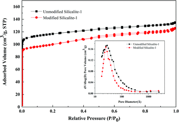 | ||
| Fig. 7 Nitrogen adsorption–desorption isotherms and pore size distributions of the modified and unmodified silicalite-1 zeolite powders. | ||
| Samples | Physical adsorption (BET) surface area (m2 g−1) | Micropore area (m2 g−1) | Total pore volume (cm3 g−1) | Micropore volume (cm3 g−1) |
|---|---|---|---|---|
| Unmodified silicalite-1 | 356.11 | 286.39 | 0.2088 | 0.1499 |
| Modified silicalite-1 | 311.70 | 228.11 | 0.1949 | 0.1179 |
3.4 SEM analysis
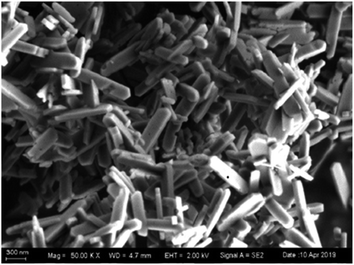
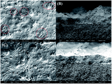
The morphology of the silicalite-1 zeolites is presented in Fig. 8. The silicalite-1 zeolites exhibit a rod-like morphology with a length of ∼1.0 μm and width of ∼10 nm. It has been reported in the literature65 that with increasing length-to-width ratio, the hydrophobicity of silicalite-1 zeolites is enhanced, which increases the compatibility between the zeolites and the PDMS matrix. Moreover, silicalite-1 zeolites with smaller particle sizes have better compatibility with the PDMS matrix. Better compatibility between the silicalite-1 zeolites and the PDMS matrix can improve the separation performance of the silicalite-1/PDMS composite membranes. Thus, silicalite-1 zeolites with rod-like morphology and small particle size are a good choice to prepare silicalite-1/PDMS composite membranes.Fig. 9 shows the surface and cross-sectional morphologies of the unmodified and modified silicalite-1/PDMS composite membranes. All the unmodified and the modified silicalite-1 zeolite particles disperse into the PDMS matrix. Evidently, the unmodified and modified silicalite-1/PDMS composite membranes are all dense and continuous with good homogeneity. From the cross-sectional views (Fig. 9B and D), it can be found that the thickness of the silicalite-1/PDMS composite membranes is about 12 μm. Moreover, the top layers of all these membranes combine tightly with the PVDF supports. It is easy to find that modified silicalite-1 zeolite particles disperse more uniformly in the PDMS matrix and the unmodified silicalite-1 zeolite particles aggregate noticeably, resulting in some stacking pinholes. The reason for this appearance is the hydrophobic surface of the silicalite-1 zeolites formed by the modification.59 The hydrophobic surfaces of the silicalite-1 zeolites improve the interfacial adhesion and compatibility, decreasing the interfacial void between the modified silicalite-1 zeolite particles and PDMS, which makes the modified silicalite-1 zeolite particles dispersing evenly in the PDMS matrix. Conceivably, the dense and continuous silicalite-1/PDMS layers without any obvious cracks and zeolite aggregation on the modified silicalite-1/PDMS composite membranes might have excellent pervaporative separation performance of DCB isomers from their mixtures.
3.5 Pervaporation performance analysis
To our knowledge, cracks, large pores, non-zeolite mesopores, non-zeolite micropores and zeolite channels are the five types of pores existing in the active layers of silicalite-1/PDMS composite membranes. As an ideal separation material, the zeolite channels should be the only type of pore existing in the active layers of the dense and continuous silicalite-1/PDMS composite membranes. Silicalite-1 zeolites have the pore dimensions 0.53 × 0.56 nm and 0.51 × 0.57 nm, which can let molecules with smaller sizes pass through and intercept larger molecules. Therefore, 1,3,5-triisopropylbenzene (TIPB, kinetic diameter: 0.85 nm) was chosen as a pervaporation agent to check the defects of the silicalite-1/PDMS composite membranes before the pervaporative separation of DCB isomers.66 The appearance of TIPB pervaporation fluxes indicates the existence of larger pores, indicating defects in the silicalite-1/PDMS composite membranes. In our experiments, all silicalite-1/PDMS composite membranes showed no flux of TIPB, indicating that the silicalite-1/PDMS composite membranes are dense without large pores except for the zeolite channels.Fig. 10 shows the fluxes of single DCB isomers via pervaporative separation through the unmodified and modified silicalite-1/PDMS composite membranes. The flux curves of p-DCB, o-DCB and m-DCB all present a rise to a maximum value at the beginning of the pervaporation and then decrease gradually to a relatively constant value with the extension of pervaporation. This phenomenon can be explained by the adsorption–diffusion mechanism during the pervaporation process. The DCB isomers are adsorbed by the silicalite-1 zeolite first and then diffuse through the silicalite-1 zeolite pores during pervaporation. Part of the molecules of the DCB isomers gather when diffusing in the silicalite-1 zeolite channels, resulting in the blocking of the silicalite-1 pores. Compared with the unmodified silicalite-1/PDMS composite membranes, the modified silicalite-1/PDMS composite membranes have lower fluxes of p-DCB, o-DCB and m-DCB. The decreased pore volume of the zeolites after modification and the reduced free volume of the membranes with the incorporation of the modified silicalite-1 zeolites are responsible for the lower fluxes.59
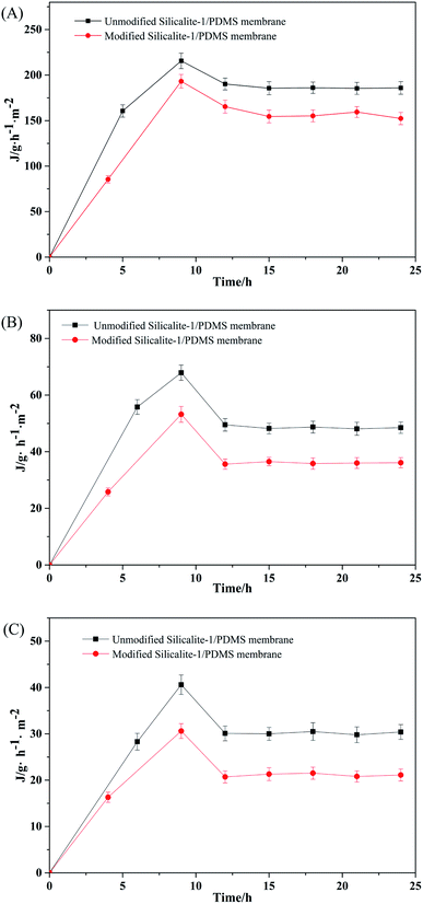 | ||
| Fig. 10 Pervaporation flux results of the unmodified and modified silicalite-1/PDMS composite membranes in a single-isomer system: p-DCB (A), o-DCB (B) and m-DCB (C). | ||
As the DCB isomers show different affinities with the silicalite-1 zeolites, there must be competitive adsorption between the isomers in the mixed system, according to the adsorption–diffusion mechanism. The pervaporative separation experiments of binary-isomer systems with equal molar content through the unmodified and modified silicalite-1/PDMS composite membranes were carried out to further evaluate the separation properties of the DCB isomers.
Fig. 11 represents the pervaporation fluxes in the p-/o-DCB and p-/m-DCB binary-isomer systems. The fluxes of p-DCB in all the binary-isomer systems present a similar trend to the single-isomer systems. However, in binary-isomer systems, the fluxes of o-DCB and m-DCB increase gradually to a relatively constant value along with the progress of the pervaporation, which shows a big difference from the single-isomer system. In a binary-isomer system, owing to the similar molecular size of p-DCB to the pore size of the silicalite-1 zeolites and the hydrophobic outer surfaces of the modified silicalite-1 zeolites, the silicalite-1 zeolite channels present preferential adsorption of p-DCB. Partial p-DCB molecules may block some zeolite channels during the pervaporation process. The blocked channels make the permeation fluxes of the o-DCB and m-DCB molecules relatively small. This phenomenon clearly suggests the existence of competitive adsorption between the DCB isomers in the unmodified and modified silicalite-1/PDMS composite membranes under the pervaporation conditions of the binary-isomer systems.
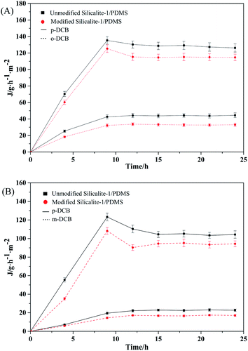 | ||
| Fig. 11 The pervaporation results from the equimolar binary-isomer systems through the unmodified and modified silicalite-1/PDMS composite membranes: p-/o-DCB (A), p-/m-DCB (B). | ||
Fig. 12 shows the pervaporative separation results of the unmodified and modified silicalite-1/PDMS composite membranes under the binary-isomer systems. The modified composite membranes have a stronger affinity for p-DCB because of their hydrophobic surface. Second, the pore size and volume of the silicalite-1/PDMS composite membranes have relatively higher separation factors towards p/o-DCB and p/m-DCB. This can be ascribed to three reasons. First, the modified silicalite-1/PDMS composite membranes have a stronger affinity for p-DCB because of the hydrophobic surface. Second, the pore size and volume of the modified silicalite-1 zeolites decrease, as shown in Fig. 7 and Table 1. Owing to the smaller pore size, fewer o-DCB or m-DCB molecules can diffuse through the zeolite channels. Third, there are fewer pinholes formed by the accumulation of particles in the modified silicalite-1/PDMS composite membranes.
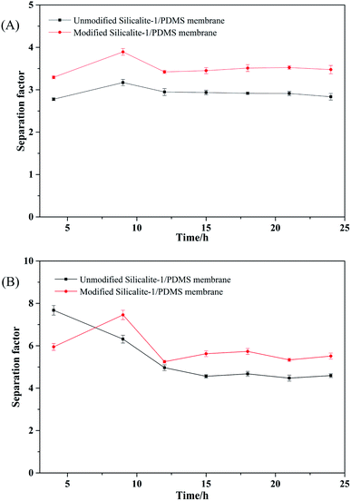 | ||
| Fig. 12 The separation factor results of the equimolar binary-isomer systems through the unmodified and modified silicalite-1/PDMS composite membranes: p-/o-DCB (A), p-/m-DCB (B). | ||
The total permeation fluxes of the DCB isomers through the unmodified and modified silicalite-1/PDMS composite membranes in both the single-isomer and binary-isomer systems are shown in Table 2. The values of the final permeation fluxes of the DCB isomers are the average of several data as the fluxes reach stability. The experimental error of most of the data during the pervaporation process of the DCB isomers in our experiments is about 3%. In the single-isomer systems, the final permeation fluxes of p-DCB, o-DCB and m-DCB through the unmodified silicalite-1/PDMS composite membranes are 186.6, 48.6 and 30.2 g m−2 h−1, respectively. The final permeation fluxes of p-DCB, o-DCB and m-DCB through the modified silicalite-1/PDMS composite membranes are 157.3, 36.0 and 21.1 g m−2 h−1, respectively. The fluxes through the unmodified and modified silicalite-1/PDMS composite membranes are all in the order of p-DCB > o-DCB > m-DCB, which can also be noted in Fig. 10. As reported in the literature, p-DCB can be absorbed and diffused through the zeolite channels easily because of its similar size to the silicalite-1 zeolite pore channels.16 o-DCB can squeeze into the silicalite-1 zeolite pores and permeate through the pores, although its molecular size is larger than the pore size of the silicalite-1 zeolites. This phenomenon can be explicated by two reasons.15 One is the distortion of neighbouring chloro-groups in the o-DCB isomers. The other one is the distorted expansion of the silicalite-1 zeolites when contacting aromatic molecules. m-DCB (molecular size: 0.68 nm) cannot enter the silicate-1 zeolite pores theoretically due to size exclusion, but there are still very few fluxes of m-DCB because of the pinholes formed by the accumulation of particles. Moreover, the fluxes of the DCB isomers through the modified silicalite-1/PDMS composite membranes are lower than those through the unmodified silicalite-1/PDMS composite membranes because of the smaller pore size of the zeolites and the fewer stacking pinholes after surface modification. The same phenomenon happens in the binary-isomer system; however, the fluxes of the DCB isomers are all lower than those in the single-isomer systems because of the competitive adsorption between the isomers. The total fluxes through the modified silicalite-1/PDMS composite membranes in the p/o-DCB and p/m-DCB systems are 149.76 and 110.12 g m−2 h−1, respectively.
| DCB isomer system | Total flux (g m−2 h−1) | ||
|---|---|---|---|
| Unmodified | Modified | ||
| Single | p-DCB | 186.6 | 157.3 |
| o-DCB | 48.6 | 36.0 | |
| m-DCB | 30.2 | 21.1 | |
| p-/o-DCB | p-DCB | 129.5 | 116.7 |
| o-DCB | 44.1 | 33.06 | |
| p-/m-DCB | p-DCB | 105.5 | 93.5 |
| m-DCB | 22.15 | 16.62 | |
Table 3 shows the separation factors of the DCB isomers through the unmodified and modified silicalite-1/PDMS composite membranes, which are calculated from the total pervaporation flux results in Table 2. The ideal separation factors are calculated from the fluxes of the DCB isomers in the single-isomer systems. The ideal separation factors of p-/o-DCB and p-/m-DCB through the modified silicalite-1/PDMS composite membranes are 4.37 and 7.46, respectively. In the binary system, the separation factors of p-/o-DCB and p-/m-DCB through the modified silicalite-1/PDMS composite membranes are 3.53 and 5.63, respectively.
Generally, the modified silicalite-1/PDMS composite membranes present a higher separation factor of DCB isomers and show competitive application in this field.
4. Conclusions
In this study, NH3–C3H6–Si(OC2H5)3 has been used to modify pristine silicalite-1 zeolites. The results clearly show that the modified silicalite-1 zeolite particles have more hydrophobic surface properties and smaller pore sizes. The silicalite-1/PDMS zeolite composite membranes have been prepared on porous PVDF supports. All the membranes have a similar thickness. The thicknesses of the unmodified and modified silicalite-1/PDMS composites are about 12 μm. The modified silicalite-1/PDMS composite membranes present a more homogeneous morphology and lower accumulation of zeolite particles because of the more hydrophobic surface. From the results of pervaporation, the permeation fluxes of the DCB isomers through the silicalite-1/PDMS composite membranes all decrease in the order of p-DCB > o-DCB > m-DCB in both the single-isomer and binary-isomer systems. Compared with the unmodified silicalite-1/PDMS composite membranes, the modified silicalite-1/PDMS composite membranes present better selective performance for the DCB isomers. The separation factors of the modified silicalite-1/PDMS composite membranes for p-/o-DCB and p-/m-DCB are 3.53 and 5.63, respectively. The total permeation flux of the modified silicalite-1/PDMS composite membranes in the p-/o-DCB binary system is 149.76 g m−2 h−1 and in the p-/m-DCB binary system, it is 110.12 g m−2 h−1. It has been confirmed that the surface modification of zeolites is a very utilitarian way to improve the performance of silicalite-1/PDMS composite membranes during pervaporative separation. The modified silicalite-1/PDMS composite membranes provide a new strategy for the separation of DCB isomers with low energy consumption and high efficiency. There is a lot of work left in the future to enhance the separation factor.Conflicts of interest
There are no conflicts to declare.Notes and references
- L. Gao and C. Fu, C. N. Patent, 111116309, 2020-05-08.
- X. Peng, Y. Li, Z. Luan, Z. Di, H. Wang, B. Tian and Z. Jia, Chem. Phys. Lett., 2003, 376, 154–158 CrossRef CAS.
- Q. H. Le, J. X. Su and J. L. Tu, J. Chem. Eng. Chin. Univ., 2001, 15, 11–16 CAS.
- J. Milam, W. Dean and R. K. Gerdes, US Pat., 04089909, 1978-05-16.
- R. Fu, W. Wu and L. X. Tian, Chem. Reagents, 1984, 6, 81–85 CAS.
- Q. Chen, Z. Gu, Z. Ma and H. Song, Comput. Appl. Chem., 2008, 25, 1505–1507 CAS.
- M. Beth and G. G. Michael, US Pat., 4996380, 1991-02-26.
- J. Susumu, I. Masami and H. Hiroaki, J. P. Patent, 58174336A, 1983-10-13.
- C. Li, J. Wang, Y. Zhang and F. Chen, Petrochem. Technol., 1992, 22, 155–159 Search PubMed.
- B. Lin, G. Hu, Y. Wang and D. Li, J. Shenyang Univ. Chem. Technol., 1998, 12, 245–251 CAS.
- R. Sun, G. Guo, L. Wang, T. Wu and Y. Long, Petrochem. Technol., 2001, 30, 178–181 Search PubMed.
- T. Kaneshikl, O. Narukawa, T. Haneda and T. Endo, US Pat., 4873383, 1989-10-10.
- H. Wang, X. Wang and D. Jiang, China Chlor-Alkali, 2008, 1, 31–33 Search PubMed.
- G. Guo, J. Wang and Y. Long, Adv. Fine Petrochem., 2000, 1, 28–32 Search PubMed.
- Q. P. He, Y. Zou, P. F. Wang and X. M. Dou, ACS Omega, 2021, 6, 8456–8462 CrossRef CAS PubMed.
- G. Guo and Y. Long, Petrochem. Technol., 2001, 30, 121–125 CAS.
- L. Fagiolar, E. varaia, N. Mariotti, M. Bonomo and C. Barolo, Adv. Sustainable Syst., 2021, 5, 2100025–2100056 CrossRef.
- M. Reina, A. Scalia, G. Auxilia, M. Fontana, F. Bella, S. Ferrero and A. Lamberti, Adv. Sustainable Syst., 2022, 6, 2100228–2100235 CrossRef CAS.
- M. Alidoost, A. Mangini, F. Caldera, A. Anceschi, J. Amici, D. Versaci, L. Fagiolari, F. Trotta, C. Francia, F. Bella and S. Bodoardo, Chem.–Eur. J., 2022, 28, 202104201–202104211 CrossRef PubMed.
- M. A. A. M. Abdah, M. Mokhtar, L. T. Khoon, K. Sopian, N. A. Dzuikurnain, A. Ahmad, Y. Sulaiman, F. Bella and M. S. Su'ait, Energy Rep., 2021, 7, 8677–8687 CrossRef.
- M. Zhang, Y. Shan, Q. Kong and H. Pang, FlatChem, 2022, 32, 10032–10048 CrossRef.
- A. Grbović, G. Kastratović, Ž. Božić, I. Božić, A. Obradović, A. Sedmak and S. Sedmak, Eng. Failure Anal., 2022, 137, 106286–106299 CrossRef.
- I. Baskar, M. Chellapandian and K. Jeyasubramanian, Constr. Build. Mater., 2022, 338, 127663–127670 CrossRef.
- Y. Nie, D. Yue, W. Xiao, W. Wang, H. Chen, L. Bai, L. Yang, H. Yang and D. Wei, Chem. Eng. J., 2022, 436, 135243–135252 CrossRef CAS.
- X. Xia, S. Zhao, H. Yin and G. J. Weng, Mater. Des., 2022, 216, 110557–110567 CrossRef CAS.
- K. Liu, C. Yang, S. Zhang, Y. Wang, R. Zou, Alamusi, Q. Deng and N. Hu, Mater. Des., 2022, 218, 110689–110696 CrossRef CAS.
- P. Paik, A. Gedanken and Y. Mastai, Microporous Mesoporous Mater., 2010, 129, 82–89 CrossRef CAS.
- P. Paik, A. Gedanken and Y. Mastai, J. Mater. Chem., 2010, 20, 4085–4093 RSC.
- P. Paik, A. Gedanken and Y. Mastai, ACS Appl. Mater. Interfaces, 2009, 1, 1834–1842 CrossRef CAS PubMed.
- X. Li, C. Jiao, X. Zhang, Z. Tian, X. Xu, F. Liang, G. Wang and H. Jiang, J. Cleaner Prod., 2022, 350, 131468–131475 CrossRef CAS.
- R. R. Gonzales, N. kato, H. Awaji and H. Matsuyama, Sep. Purif. Technol., 2022, 285, 120369–120376 CrossRef CAS.
- S. Liu, W. Li, C. Chen, J. Chen, X. Wu and J. Wang, J. Membr. Sci., 2022, 644, 120165–120174 CrossRef CAS.
- S. L. Wu, F. Liu, H. C. Yang and S. B. Darling, Mol. Syst. Des. Eng., 2020, 5, 433–444 RSC.
- L. wang, X. Wu, W. Xu, X. Huang, J. Liu and A. Xu, ACS Appl. Mater. Interfaces, 2012, 4, 2686–2692 CrossRef CAS PubMed.
- Q. Wang, X. Wu, J. Chen, W. Li and J. Wang, Chem. Eng. Sci., 2020, 228, 116002–116008 CrossRef CAS.
- N. Liu, L. Zhang, R. Cai, Z. Zhou and H. Chen, Chem. Ind. Eng. Prog., 2007, 26, 804–809 CAS.
- G. Erdem, M. Leckebusch, G. Olf, K. J. Rinck and G. Zülke, US Pat., 7311807, 2007-12-25.
- T. Uragami, K. Okazaki, H. Matsugi and T. Miyata, Macromolecules, 2002, 35, 9156–9163 CrossRef CAS.
- Y. Bai, L. Dong, Y. Zhu, C. Zhang, J. Gu and Y. Xu, RSC Adv., 2015, 5, 52759–52768 RSC.
- Y. jie, S. Yang, Z. Du, B. li, Z. wang, S. V. Agtmmal, C. Feng and B. Han, J. Membr. Sep. Technol., 2013, 2, 148–152 Search PubMed.
- T. Miyata, J. Higuchi, H. Okuno and T. Uragami, J. Appl. Polym. Sci., 1996, 61, 1315–1324 CrossRef CAS.
- Y. Liu, T. Hu, J. Zhao, L. Lu, Y. Muhammad, P. Lan, R. He, Y. Zou and Z. Tong, J. Membr. Sci., 2019, 591, 117324–117339 CrossRef.
- A. Hoda, E. Arian, T. F. Handan and T. Jules, Membranes, 2018, 8, 40–54 CrossRef PubMed.
- Z. Si, S. Hu, D. Cai, P. Qin and Q. Xu, RSC Adv., 2018, 8, 5127–5135 RSC.
- G. Zhang, C. Wu, M. Wey and H. Tseng, Membranes, 2021, 11, 59–74 CrossRef PubMed.
- C. Denka, J. Appl. Polym. Sci., 2020, 137, 48549–48556 CrossRef.
- C. Cheng, F. Liu, H. K. Yang, K. Xiao and S. T. Yang, Ind. Eng. Chem. Res., 2020, 59, 7777–7786 CrossRef CAS.
- K. P. Ramaiah, D. Satyasri, S. Sridhar and A. Krishnaiah, J. Hazard. Mater., 2013, 261, 362–371 CrossRef CAS PubMed.
- S. A. Alavi, A. Kargari, H. Sanaeepur and M. Karimi, Res. Chem. Intermed., 2017, 43, 2959–2984 CrossRef CAS.
- H. Han, Y. Liu, L. Liang, J. Yang, Z. Zhou and J. Wang, Membr. Sci. Technol., 2010, 30, 39–43 CAS.
- X. Zhuang, X. Chen, Y. Su, J. Luo, W. Cao and Y. Wan, J. Membr. Sci., 2015, 493, 37–45 CrossRef CAS.
- R. Wang, L. Shan, G. Zhang and S. Ji, J. Membr. Sci., 2013, 432, 33–41 CrossRef CAS.
- S. J. Lue, C. F. Chien and K. P. O. Mahesh, J. Membr. Sci., 2011, 384, 17–26 CrossRef CAS.
- J. Liu, J. Chen, X. Zhan, M. Fang, T. Wang and J. Li, Sep. Purif. Technol., 2015, 150, 257–267 CrossRef CAS.
- G. Xue and B. Li, Adv. Polym. Technol., 2018, 37, 3095–3105 CrossRef CAS.
- F. Banihashemi, M. Pakizeh and A. Ahmadpour, Sep. Purif. Technol., 2011, 79, 293–302 CrossRef CAS.
- D. Li, J. Yao, H. Sun, B. Liu, S. Agtmaal and C. Feng, Appl. Surf. Sci., 2018, 427, 288–297 CrossRef CAS.
- H. Zhou, Y. Su, X. Chen, S. Yi and Y. Wan, Sep. Purif. Technol., 2010, 75, 286–294 CrossRef CAS.
- X. Han, X. Zhang, X. Ma and J. Li, Polym. Compos., 2016, 37, 1282–1291 CrossRef CAS.
- H. Sun, L. Lu, C. Xue and Z. Jiang, Appl. Surf. Sci., 2008, 254, 5367–5374 CrossRef CAS.
- L. Ji, B. Shi and L. Wang, J. Appl. Polym. Sci., 2015, 132, 41897–41905 CrossRef.
- C. Lin, L. Wu, X. Qu, Z. Lin and H. Chen, Technol. Water Treat., 2011, 37, 28–32 Search PubMed.
- X. Han, L. Wang, J. Li, X. Zhan, J. Chen and J. Yang, Appl. Surf. Sci., 2011, 257, 9525–9531 CrossRef CAS.
- L. Wang, L. Yu, Z. Xue and Y. Cao, China Ceram., 2016, 52, 78–82 CAS.
- N. Wang, J. Liu, J. Li, J. Gao, S. Ji and J. Li, Microporous Mesoporous Mater., 2015, 201, 35–42 CrossRef CAS.
- W. Yuan, Y. S. Lin and W. Yang, J. Am. Chem. Soc., 2004, 126, 4776–4777 CrossRef CAS PubMed.
| This journal is © The Royal Society of Chemistry 2022 |

