
 Open Access Article
 This Open Access Article is licensed under a
 Creative Commons Attribution 3.0 Unported Licence
Thermoelectric performance enhancement of eco-friendly Cu2Se through incorporating CB4
Wen Xie,
Feng Liu,
Yingxiang Zheng,
Nina Ge ,
Bo Dai and
Xiaowei Zhang*
,
Bo Dai and
Xiaowei Zhang*
State Key Laboratory of Environment-Friendly Energy Materials, Southwest University of Science and Technology, Mianyang, 621010, China. E-mail: hedge80@sina.com.cn; Fax: +86-0816-2419-492; Tel: +86-0816-2419-492
First published on 11th May 2022
Abstract
We have prepared Cu2Se + x wt% CB4 composites with x = 0, 0.1, 0.3, 0.5, and 0.7 by a hydrothermal method and hot-pressing technique. The structural and compositional analysis indicates that pure phase Cu2Se powders were synthesized and the densified layered bulk samples were obtained. Electrical properties testing showed that the sample with x = 0.5 has the high power factor of 0.886 mW m−1 K−2 due to its high Seebeck coefficient. Meanwhile, the thermal conductivity was suppressed to 0.6 W m−1 K−1 at 773 K. As a result, the final optimized ZT value of 1.46 at 773 K was achieved. These results suggest that CB4 could be an alternative inclusion to improve effectively the thermoelectric performance of Cu2Se.
1. Introduction
With the wide demand for environment-friendly energy, thermoelectric (TE) materials have received significant attention during the past two decades.1–6 TE materials can realize the conversion directly between thermal and electrical energy.7–9 High-efficiency TE materials require a high dimensionless figure of merit (ZT), ZT = S2σT/κ, where S is the Seebeck coefficient, σ is the electrical conductivity, T is the absolute temperature, and κ is the total thermal conductivity respectively.10–13 Numerous exploratory efforts tried to optimize these parameters, i.e., enhance the power factor (PF = S2σ) and reduce the thermal conductivity simultaneously, to achieve high TE performance.14,15 However, these parameters are strongly coupled together, making it challenging to improve the ZTs.16,17Chalcogenide TE materials have attracted widespread interests and have been intensively studied because of their intrinsically low lattice thermal conductivity (κL).18–21 Very recently, Chung and co-workers reported22 the ultralow κL of 0.07 W m−1 K−1 obtained in polycrystal SnSe and thereby got a high ZT of 3.1, which breaks thermoelectric performance limits.23 Cu-based chalcogenide also received much attention for environmental-friendly TE application and Cu2Se is one of the strongest candidates.24,25 To improve the TE performance of Cu2Se, numerous strategies have been developed, such as nano-engineering,26,27 solid solution alloying,28,29 element doping,30–32 and introducing highly dispersed nanoparticles.33–36 Among them, adding nanoparticles to Cu2Se matrix has been demonstrated to be an effective and prevailing approach to improve TE performance. The nanoparticles in composites, such as TiO2,37 graphene,38 nano-boron,39 carbon dots40,41 and CNTs,42 can effectively scatter intermediate frequency phonons and hence suppress κL.
In this work, we try to introduce boron carbide (CB4) as a second phase in the Cu2Se matrix because nano-CB4 has good thermal stability, high temperature electrical conductivity and relatively large Seebeck coefficient.43 For preparing Cu2Se samples with different contents of CB4, the hydrothermal method and hot-pressing technique are employed. The results show that CB4 inclusions do reduce κ significantly and meanwhile enhance PF slightly over a wide range of temperature. As a result, the highest ZT reaches 1.46 at 773 K, which is much higher than the value of undoped sample.
2. Experimental section
Cu2Se nanopowders were prepared by hydrothermal method and CB4 nanopowders were added during the hydrothermal process. We first mixed 20 mmol copper chloride dehydrate (CuCl2·2H2O, 99.9%), 10 mmol selenium dioxide (SeO2, 99.9%) and a recommended amount of CB4 (99%) into about 60 milliliters deionized water, and then magnetic stirred continuously for 12 h. The amount of CB4 is determined by the mass ratio of Cu2Se and CB4. In this work, we consider five Cu2Se + x wt% CB4 (x = 0, 0.1, 0.3, 0.5, 0.7) samples, which are named as S0, S1, S3, S5 and S7 respectively for the convenience of description. After the components were completely dissolved, we added 20 milliliters hydrazine hydrate (N2H4·H2O) into the mixture solution. The solution was then loaded into a Teflon-lined stainless steel autoclave and sealed. The autoclave was heated at 453 K for 24 h and cooled down to room temperature naturally. The product was collected by centrifuging and washed by deionized water and anhydrous ethanol for several times. We finally dried the product in vacuum at 333 K for at least 12 h. For getting the final samples, the synthesized powders were sintered into pallets with a diameter of 20 mm by hot-pressing method at 973 K and under a pressure of 40 MPa in the vacuum for 30 minutes.The phase compositions of the prepared samples were identified by X-ray diffraction measurements (XRD, PANalytical, Netherlands) with Cu Kα radiation. The fracture surface microstructure was observed by field emission scanning electron microscopy (SEM, TM4000) and Energy-dispersive X-ray spectroscopy (EDS, X-MAXN20, England). Seebeck coefficients and electrical conductivity simultaneously were measured by using a CTA-3 system (Cryoall, China) from 323 K to 773 K in a helium atmosphere. κ was calculated according to the formula κ = ρDCp, where ρ is the density of the samples, D is the thermal diffusivity, and Cp is the heat capacity respectively. D was measured using the laser flash method (DFL-1600, Netzsch) on a square piece specimen with 10 mm in side and 1.5 mm in thickness. Cp was measured by differential scanning calorimetry (DSCQ-2000, TA). The density of the samples ρ was obtained from Archimedes' method.
3. Results and discussion
Fig. 1(a) shows the XRD patterns of the synthesized Cu2Se + x wt% CB4 (x = 0, 0.1, 0.3, 0.5, 0.7) nanopowders. The main diffraction peaks are all in consistent with the ICDD file No. 00-006-0680, indicating β-phase Cu2Se is prepared successfully.40,44–46 No CB4 phase is to be detected, which might be due to introducing only a small amount into the main β-phase Cu2Se. Fig. 1(b) shows the XRD patterns of the sintered bulk samples. The results match with the ICDD file No. 00-019-0401 very well, indicating that the as-prepared β-Cu2Se nanostructures has transferred to pure α-Cu2Se after sintering.40,46,47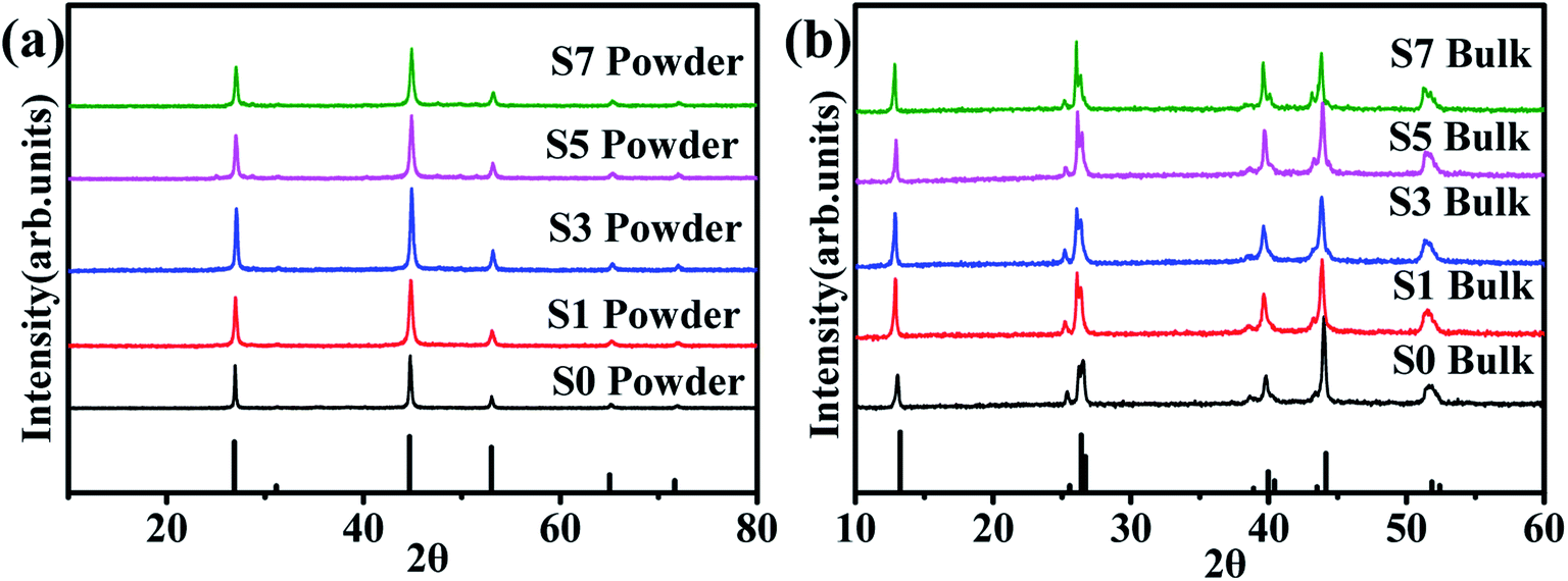 | ||
| Fig. 1 (a) XRD patterns of the β-Cu2Se (ICDD file No. 00-006-0680) synthesized nanopowders. (b) XRD patterns of α-Cu2Se (ICDD file No. 00-019-0401) bulk samples. | ||
The typical morphology of the synthesized Cu2Se precursor nanopowders is shown in Fig. 2(a). Nanoplates with a lateral size of 100–500 nm, often aggregating together, can be clearly observed. Fig. 2(b–f) display the cross-sectional microstructures of the hot-pressed Cu2Se + x wt% CB4 bulk samples. Similar lamellar structure is observed for each sample. Such structure is conducive to reducing the thermal conductivity due to the increased scattering of phonons between layered interfaces.48 A few pores on the surface can be spotted which might be due to Se volatilization during the sintering process and hence the corresponding density is slightly lower than the pure Cu2Se. The samples S0, S1, S3, S5, and S7 have densities of 5.75, 5.65, 5.38, 5.29, 5.20 g cm−3 respectively (theoretical density of Cu2Se is 6.74 g cm−3). Fig. 3 shows the surface EDS mapping of the sample S5. These maps suggest that copper, selenium, carbon and boron signals overlap, showing CB4 is uniformly distributed in the sample.
 | ||
| Fig. 2 SEM images for (a) Cu2Se nanopowders, the samples of (b) S0, (c) S1, (d) S3, (e) S5 and (f) S7. | ||
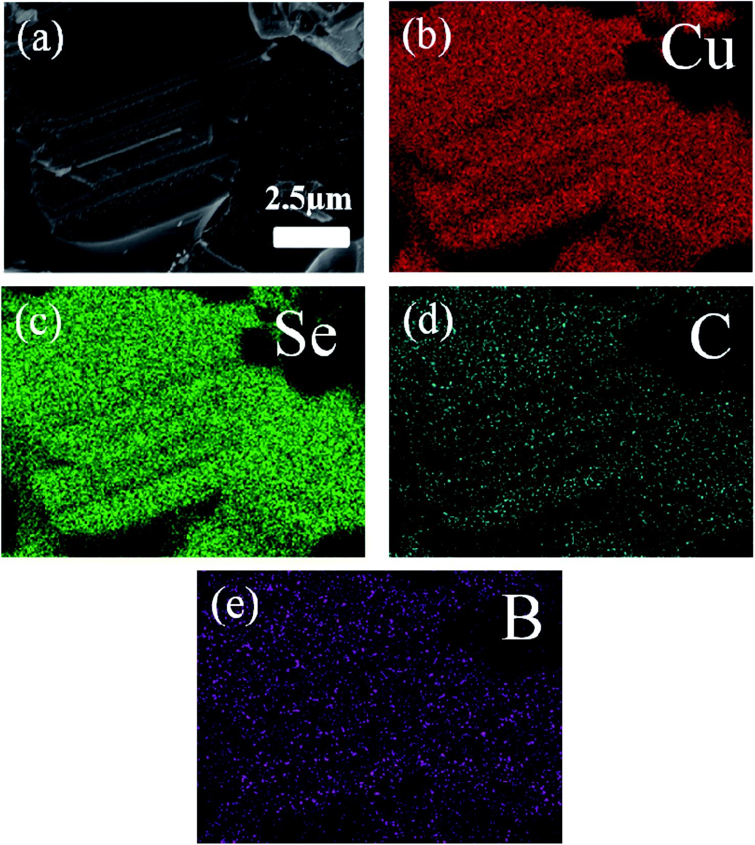 | ||
| Fig. 3 (a) SEM image of the typical morphology of the S5. (b)–(e) The corresponding EDS maps. | ||
The temperature dependence of the electrical conductivity σ of our samples is shown in Fig. 4(a). Within the temperature range of 400–773 K, the electrical conductivity σ of all samples decreases monotonously with temperature increasing, which shows the typical behaviors of metallic-like characteristic. However, we can clearly find that the electrical conductivity σ varies abnormally around 400 K, which have been proved to be due to the phase transition from α-Cu2Se to β-Cu2Se.49 In addition, the electrical conductivity σ decreases with the increasing of CB4 components at each testing temperature. For example, compared to the sample S0, the electrical conductivity σ is about 3 times smaller around 400 K and 2 times smaller at 773 K for the sample S7. This trend in electrical conductivity σ is very different from the report of Cu2Se/SiC composite,27 but similar to the report of Cu2S/SiC composite.17 For clarifying the underlying mechanism of the electrical transport behaviors, the room temperature carrier concentration (n) and carrier mobility (μ) are measured, as shown in Table 1. Clearly, there is a reduction in carrier concentration and an increase in carrier mobility with increasing of the CB4 composite content. For the superionic conductor Cu2Se, unstable copper ions show a liquid-like behavior and hence cause the unrepeatable electrical transport properties. The carrier concentration n contains two parts: the majority carrier (nhole) and the ion carrier (nion), and therefore, the electrical conductivity σ = σhole + σion. In our work, the introduction of CB4 might effectively block the migration of copper ions, which causes the reduction in nion and hence in the whole carrier concentration n. In addition, the migration restrictions of copper ions can also effectively enhance the stability of Cu2Se chemical structure, which is confirmed by the cyclic testing shown in Fig. 4. The increase in mobility μ might be due to the grain growth during the process of hot pressing, as can be clearly seen in Fig. 2. Because of the difficulty for measuring the transport of ions, more related discussions do not be present here.
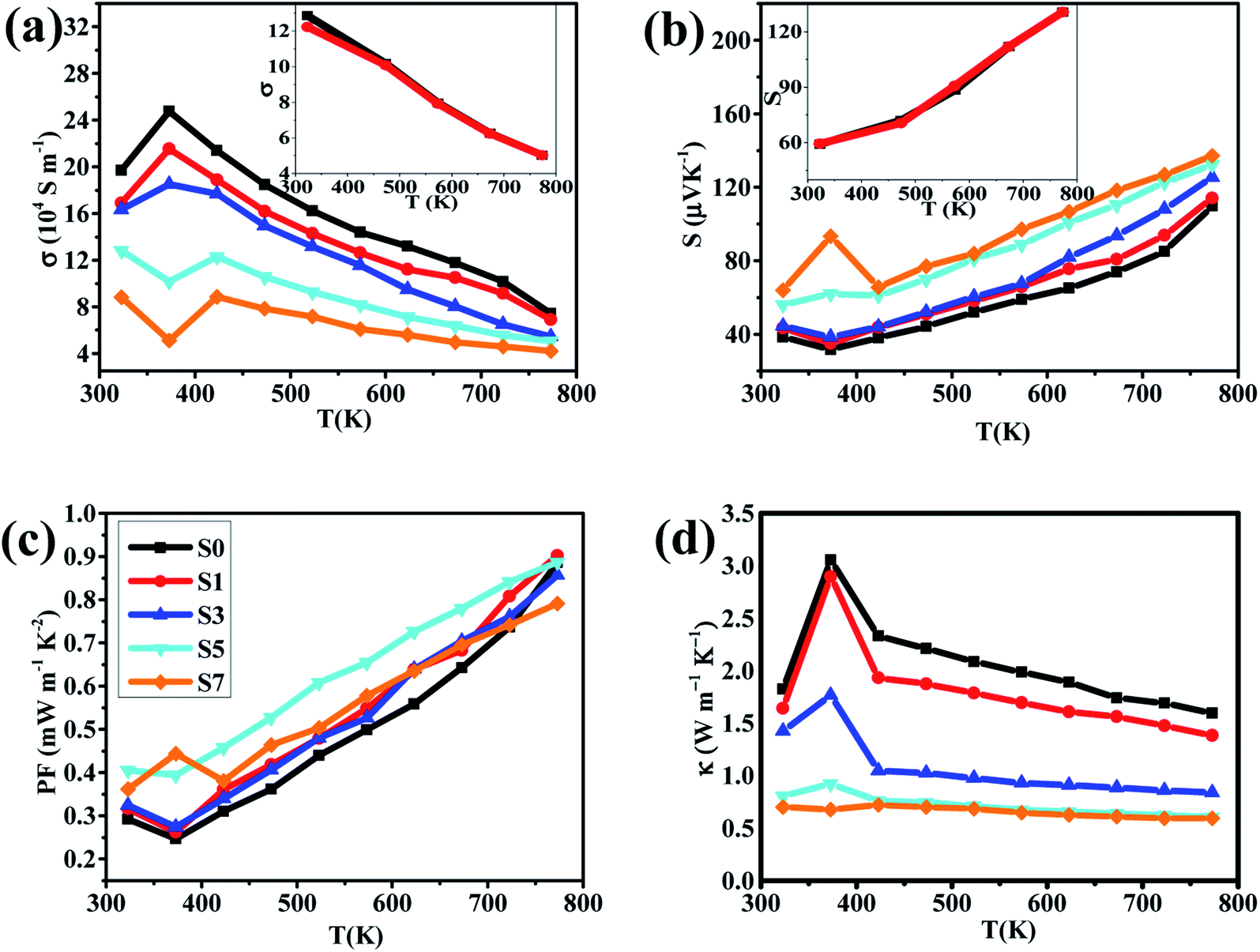 | ||
| Fig. 4 Temperature dependence of (a) electrical conductivities, (b) Seebeck coefficients, (c) power factors and (d) thermal conductivities for the samples of S0, S1, S3, S5 and S7. Insets of (a) and (b) are the heating (red line) and cooling (black line) curves for electrical conductivity and Seebeck coefficient of sample S5 respectively. | ||
| Sample | nhole + nion (1019 cm−3) | μ (cm2 V−1 s−1) |
|---|---|---|
| S0 | 7.9 | 73.6 |
| S1 | 6.6 | 101 |
| S3 | 5.5 | 104 |
| S5 | 5.3 | 112 |
| S7 | 3.6 | 119 |
In our work, the samples S5 and S7 show a quite low electrical conductivity σ. This fact would not be very good for optimizing the thermoelectric properties of Cu2Se. However, thankfully, the reduction in electrical conductivity σ is often accompanied by enhancement of the Seebeck coefficient. As we can see from Fig. 4(b), the samples S5 and S7 exhibit a larger Seebeck coefficient than the others within the entire testing temperature range and the optimal value reaches 137 μV K−1 at 773 K for the sample S7. Additionally, the positive Seebeck coefficient for all samples suggests the p-type electrical transport in Cu2Se. The calculated PFs of the samples are shown in Fig. 4(c). Very clearly, PFs curves of the samples S0, S1, S3 and S5 show a valley around 400 K due to the phase transition from β-Cu2Se to α-Cu2Se,50,51 while the sample S7 has the abnormal high PF because of its very high S and low σ. However, we cannot evaluate precisely these parameters around 400 K because they are very sensitive to temperature change during the process of phase transformation. This might be the reason that some previous studies did not show the related data close to 400 K.
As T >400 K, all PFs increase rapidly as temperature increases. However, the sample S7 does not show the superior PF value, which might be due to its very low electrical conductivity. In contrast, the sample S5 has the optimal PF as T >400 K (PFmax = 0.886 mW m−1 K−2 at 773 K), indicating that a moderate content of CB4 composites may result in a better electrical performance of Cu2Se.
Another important parameter to determine the TE properties is the thermal conductivity κ. The thermal conductivity can be divided into two parts: κ = κL + κcarrier, where κL comes from heat phonons travelling through the crystal lattice and κcarrier arises from heat carriers' movement. Generally, at high temperature, κL dominates in Cu2Se matrix.39 The measured thermal conductivity is shown in Fig. 4(d). Clearly, all of the thermal conductivity κ decrease with temperature increasing, which is a reasonable trend because of the increasing in phonon scattering and the reduction in carrier concentration. For a fixed temperature, as CB4 component increases from 0.0 to 0.7%, the thermal conductivity decreases very rapidly. To take a step further, carrier thermal conductivity (κcarrier) is calculated by using the Wiedemann–Franz relationship, κcarrier = LσT, where L is the Lorenz number. When the detailed band structure and scattering mechanism are not known, the Lorenz number can not be viewed as a constant but can be calculated by L = 1.5 + exp [−|S|/116], where L is in unit of 10−8 W Ω K−2 and S (Seebeck coefficient) in unit of μV K−1.52 The calculated L and κcarrier are showed in Fig. 5. However, it seems that the measured total thermal conductivity of S5 and S7 are lower than the calculated values. The similar phenomenon happened to Cu2Se/SiC system27 and Cu–S system.17,53 It might be due to the different thermal transport properties between electron/hole carriers and ion carriers. The equation κcarrier = LσT may not be suitable for Cu2Se/CB4 composite. The ion carriers have a non-negligible contribution to total thermal transport, so the modified equation can be taken as κcarrier = L (σ − σion)T + κion,27,30,53 where κion is the ionic thermal conductivity, σion is ionic electrical conductivity. However, σion and κion cannot be measured precisely now and hence the carrier thermal conductivity and lattice thermal conductivity are not offered here.
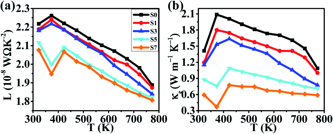 | ||
| Fig. 5 Temperature dependence of (a) the calculated Lorenz number, (b) the calculated thermal conductivities for samples of S0, S1, S3, S5 and S7. | ||
Considering the total thermal conductivity, the samples S5 and S7 remain very low values and very close to each other as T >400 K. The lowest κ value is 0.59 W m−1 K−1 at 773 K for S7 sample. This result indicates that the higher concentration of CB4 inclusions could not improve further the thermal conductivity. Moreover, as shown in Fig. 4(c), the PF of sample S7 is also smaller than sample S5. Therefore, in this work, the S5 sample would show the optimal thermoelectric performance. This can be confirmed positively by the relationship between ZT values and temperature, as shown in Fig. 6. Sample S5 exhibits the largest ZT than the others as T >400 K and the largest value is of 1.46 at 773 K, which is much larger than that of undoped sample S0 (ZTmax = 0.55 at 773 K). The average ZT value of S5 (ZTaverage = 1.034) is also larger than one within the temperature range of 400–773 K. These results suggest that Cu2Se compositing a certain amount of CB4 is very promising for TE application.
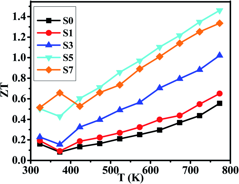 | ||
| Fig. 6 Temperature dependence of ZTs for samples of S0, S1, S3, S5 and S7. | ||
4. Conclusions
We have prepared the pure phase Cu2Se + x wt% CB4 (x = 0, 0.1, 0.3, 0.5, 0.7) nanopowders by hydrothermal method and have sintered the corresponding bulk samples by hot-pressing technique. With the content of CB4 increasing, the electrical conductivities of our samples decrease very rapidly, while the Seebeck coefficients steadily increase. The final PFs show that the sample S5 possesses the optimal value within the testing temperature range. The thermal conductivity testing confirms that the CB4 nano-inclusions can drastically reduce the κ of our samples. The lowest κ value is 0.59 W m−1 K−1 at 773 K for S7 sample. However, the κ of sample S5 is very close to that of sample S7 as T >400 K. Finally, the optimized ZT value of 1.46 at 773 K is achieved for S5 sample, which is about 165% larger than the undoped sample.Conflicts of interest
The authors have no conflicts to declare.Acknowledgements
This work is supported the Projection of State Key Laboratory of Environment-friendly Energy Materials, Southwest University of Science and Technology (No. 20FKSY23).References
- Z. G. Chen, G. Han, L. Yang, L. N. Chen and J. Zhou, Prog. Nat. Sci.: Mater. Int., 2012, 22, 535 CrossRef.
- P. Sundarraj, D. Maity, S. S. Roy and R. A. Taylor, RSC Adv., 2014, 87, 46860 RSC.
- M. Li, S. M. K. N. Islam, S. X. Dou and X. L. Wang, J. Alloys Compd., 2018, 769, 59 CrossRef CAS.
- T. J. Zhu, Y. T. Liu, C. G. Fu, J. P. Heremans, J. G. Snyder and X. B. Zhao, Adv. Mater., 2017, 29, 1605884 CrossRef PubMed.
- J. Zhang, T. Zhu, C. Zhang, Y. G. Yan, G. J. Tan, W. Liu, X. L. Su and X. F. Tang, J. Alloys Compd., 2021, 881, 857916 Search PubMed.
- M. Rull-Bravo, A. Moure, J. F. Fernandez and M. Martin-Gonzalez, RSC Adv., 2015, 24, 41653 RSC.
- J. He and T. M. Tritt, Science, 2017, 357, 1369 CAS.
- G. J. Snyder and E. S. Toberer, Nat. Mater., 2008, 7, 105 CrossRef CAS PubMed.
- L. Yang, Z. G. Chen, M. S. Dargusch and Z. Jin, Adv. Energy Mater., 2017, 8, 170197 Search PubMed.
- H. Zhu, C. Xiao and Y. Xie, Adv. Mater., 2018, 30, 180200 Search PubMed.
- X. L. Su, P. Wei, H. Li, W. Liu, Y. G. Yan, P. Li, C. Q. Su, C. J. Xie, W. Y. Zhao, P. C. Zhai, Q. J. Zhang, X. F. Tang and C. Uher, Adv. Mater., 2017, 29, 160213 Search PubMed.
- W. Suwannasri, R. Chueachot, T. Seetawan and R. Nakhowong, J. Alloys Compd., 2021, 863, 158749 CrossRef CAS.
- K. Biswas, H. J. Qing, K. Biswas, J. Q. He, I. D. Blum, C. I. Wu, T. P. Hogan, D. N. Seidman, V. P. Dravid and M. G. Kanatzidis, Nature, 2012, 489, 414 CrossRef CAS PubMed.
- Fitriani, R. Ovik, B. D. Long, M. C. Barma, M. Riaz, M. F. M. Sabri, S. M. Said and R. Saidur, Renewable Sustainable Energy Rev., 2016, 64, 635 CrossRef CAS.
- W. D. Liu, X. L. Shi, M. Hong, L. Yang, R. Moshwan, Z. G. Chen and J. Zou, J. Mater. Chem. C, 2018, 6, 13225 RSC.
- J. Shuai, J. Mao, S. W. Song, Q. Y. Zhang, G. Chen and Z. F. Ren, Mater. Today Phys., 2017, 1, 74 CrossRef.
- Q. Peng, G. Z. Hua and J. Feng, J. Alloys Compd., 2017, 696, 782 CrossRef.
- W. S. Liu, J. Z. Hu, S. M. Zhang, M. J. Deng, C. G. Han and Y. Liu, Mater. Today Phys., 2017, 1, 50 CrossRef.
- Z. X. Zhang, K. P. Zhao, T. R. Wei, P. F. Qiu, L. D. Chen and X. Shi, Energy Environ. Sci., 2020, 13, 3307 RSC.
- M. Beekman, D. T. Morelli and G. S. Nolas, Nat. Mater., 2015, 14, 1182 CrossRef CAS PubMed.
- K. P. Zhao, P. F. Qiu, L. D. Chen and X. Shi, Adv. Funct. Mater., 2020, 30, 1903867 CrossRef CAS.
- C. J. Zhou, Y. K. Lee, Y. Yu, S. Byun, Z. Z. Luo, H. Lee, B. Z. Ge, Y. L. Lee, X. Q. Chen, J. Y. Lee, O. Cojocaru-Miredin, H. Chang, J. Im, S. P. Cho, M. Wuttig, V. P. M. G. Kanatzidis and I. Chung, Nat. Mater., 2021, 20, 1378 CrossRef CAS PubMed.
- I. B. Brummerstedt, Nat. Mater., 2021, 20, 1309 CrossRef PubMed.
- H. L. Liu, X. Shi, F. F. Xu, L. L. Zhang, W. Q. Zhang, L. D. Chen, Q. Li, C. Uher, T. Day and G. J. Snyder, Nat. Mater., 2012, 11, 422 CrossRef CAS PubMed.
- L. Yang, Z. G. Chen, G. Han, M. Hong, Y. C. Zou and J. Zou, Nano Energy, 2015, 16, 367 CrossRef CAS.
- B. Gahtori, S. Bathula, K. Tyagi, M. Jayasimhadri, A. K. Srivastava, S. Singh, R. C Budhani and A. Dhar, Nano Energy, 2015, 13, 36 CrossRef CAS.
- J. D. Lei, Z. Ma, D. Zhang, Y. Q. Chen, C. Wang, X. Y. Yang, Z. X. Cheng and Y. X. Wang, J. Mater. Chem. A, 2019, 7, 7006 RSC.
- K. P. Zhao, M. J. Guan, P. F. Qiu, A. B. Blichfeld, E. Eikeland, C. X. Zhu, D. D. Ren, F. F. Xu, B. B. Iversen and L. D. Chen, J. Mater. Chem. A, 2018, 6, 6977 RSC.
- K. P. Zhao, A. B. Blichfeld, E. Eikeland, P. F. Qiu, D. D. Ren, B. B. Iversen, X. Shi and L. D. Chen, J. Mater. Chem. A, 2017, 5, 6367 CrossRef.
- Z. H. Ge, X. Y. Liu, D. Feng, J. Y. Lin and J. Q. He, Adv. Energy Mater., 2016, 6, 1600607 CrossRef.
- S. D. Kang, J. H. Pohls, U. Aydemir, P. F. Qiu, C. C. Stoumpos, R. Hanus, M. A. White, X. Shi, L. D. Chen, M. G. Kanatzidis and G. J. Snyder, Mater. Today Phys., 2017, 1, 7 CrossRef.
- W. H. Gao, Z. H. Liu, W. H. Zhang, N. Sato, Q. S. Guo and T. Mori, Appl. Phys. Lett., 2021, 118, 033901 CrossRef CAS.
- F. S. Liu, Z. N. Gong, M. J. Huang, W. Q. Ao, Y. Li and J. Q. Li, J. Alloys Compd., 2016, 688, 521 CrossRef CAS.
- R. M. Lu, A. Olvera, T. P. Bailey, C. Uher and P. F. P. Poudeu, ACS Appl. Mater. Interfaces, 2020, 12, 58018 CrossRef CAS PubMed.
- L. L. Zhao, S. M. K. N. Islam, J. Wang, D. L. Cortie, X. G. Wang, Z. X. Cheng, J. Y. Wang, N. Ye, S. X. Dou, X. Shi, L. D. Chen, G. J. Snyder and X. L. Wang, Nano Energy, 2017, 41, 164 CrossRef CAS.
- F. S. Liu, Z. N. Gong, M. J. Huang, W. Q. Ao, Y. Li and J. Q. Li, J. Alloys Compd., 2016, 688, 521 CrossRef CAS.
- F. F. Kong, J. Bai, Y. W. Zhao, Y. Liu, J. Shi, Z. Y. Wang and R. Xiong, Appl. Phys. Lett., 2019, 115, 203901 CrossRef.
- M. Li, D. L. Cortie, J. X. Liu, D. H. Yu, S. M. K. N. Islam, L. L. Zhao, D. R. G. Mitchell, R. A. Mole, M. B. Cortie, S. X. Dou and X. L. Wang, Nano Energy, 2018, 53, 9931 Search PubMed.
- S. M. K. N. Islam, M. Li, U. Aydemir, X. Shi, L. D. Chen, G. J. Snyder and X. L. Wang, J. Mater. Chem. A, 2018, 6, 18409 RSC.
- Q. J. Hu, Y. Zhang, Y. W. Zhang, X. J. Li and H. Z. Song, J. Alloys Compd., 2020, 813, 152204 CrossRef CAS.
- C. Y. Oztan, B. Hamawandi, Y. Q. Zhou, S. Ballikaya, M. S. Toprak, R. M. Leblanc, V. Coverstone and E. Celik, J. Alloys Compd., 2021, 864, 857916 CrossRef.
- R. Nunna, P. F. Qiu, M. Yin, H. Y. Chen, R. Hanus, Q. F. Song, T. S. Zhang, M. Y. Chou, M. T. Agne, J. Q. He, G. J. Snyder, X. Shi and L. D. Chen, Energy Environ. Sci., 2017, 10, 1928 RSC.
- C. Wood and D. Emin, Phys. Rev., 1984, 29, 4582 CAS.
- F. Jia, S. Zhang, X. K. Zhang, X. L. Peng, H. T. Zhang and Y. Xiang, Chem. - Eur. J., 2014, 20, 15941 CrossRef CAS PubMed.
- A. Bhaskar, C. H. Hu, C. L. Chang and C. J. Liu, J. Eur. Ceram. Soc., 2016, 36, 2755 CrossRef CAS.
- L. Yang, Z. G. Chen, G. Han, M. Hong, Y. C. Zou and Z. Jin, Nano Energy, 2015, 16, 367 CrossRef CAS.
- F. Gao, S. L. Leng, Z. Zhu, X. J. Li, X. Hu and H. Z. Song, J. Electron. Mater., 2018, 47, 2454 CrossRef CAS.
- H. Q. Jun, Z. Zheng, Y. W. Zhang, X. J. Li, H. Z. Song and Y. J. Zhang, J. Mater. Chem. A, 2018, 6, 3417 Search PubMed.
- E. Eikeland, A. B. Blichfeld, K. A. Borup, K. P. Zhao, J. Overgaard, X. Shi, L. D. Chen and B. B. Iversen, IUCrJ, 2017, 4, 476 CrossRef CAS PubMed.
- H. L. Liu, X. Yuan, P. Lu, X. Shi, F. F. Xu, Y. He, Y. S. Tang, S. Q. Bai, W. Q. Zhang, L. D. Chen, Y. Lin, L. Shi, H. Lin, X. Y. Gao, X. M. Zhang, H. Chi and C. Uher, Adv. Mater., 2013, 25, 6607 CrossRef CAS PubMed.
- D. R. Brown, T. Day, K. A. Borup, S. Christensen, B. B. Iversen and G. J. Snyder, APL Mater., 2013, 1, 052107 CrossRef.
- H. S. Kim, Z. M. Gibbs, Y. G. Tang, H. Wang and G. J. Snyder, APL Mater., 2015, 3, 041506 CrossRef.
- Y. B. Zhu, B. P. Zhang and Y. Liu, Phys. Chem. Chem. Phys., 2017, 9, 27664 RSC.
| This journal is © The Royal Society of Chemistry 2022 |