DOI:
10.1039/D2RA01491B
(Paper)
RSC Adv., 2022,
12, 16893-16902
Hydroxypropyl-β-cyclodextrin-incorporated Pebax composite membrane for improved permselectivity in organic solvent nanofiltration†
Received
7th March 2022
, Accepted 24th May 2022
First published on 7th June 2022
Abstract
Thanks to the characteristic hollow cavity structure and sustainable and nontoxic macrocycle molecule feature, cyclodextrins have been used as building block to fabricate organic solvent nanofiltration (OSN) membranes with enhanced permeability and selectivity. Herein, hydroxypropyl-β-cyclodextrin (HP-β-CD) was incorporated into a poly(ether-block-amide) (Pebax) layer on a polysulfone support, followed by crosslinking with toluene 2,4-diisocyanate to prepare a crosslinked HP-β-CD/Pebax (CHP) membrane. By adjusting the initial HP-β-CD concentration (x) and crosslinking reaction time (y), the microporous structure and surface morphology of CHPx–y (x = 0, 0.25, 0.5, 0.75; y = 5, 10, 15) membranes could be manipulated. The OSN performances of the CHPx–y membranes were evaluated by the removal of dyes in methanol solution. The results revealed that the optimal CHP0.5–10 membrane exhibited a high methanol permeance of 8.7 L m−2 h−1 bar−1, high dye rejection (>96%), and high running stability (at least 336 h), due to the intrinsically microporous structure and surface morphology. This work would inspire the further development of cyclodextrins and other macrocyclic molecules in the preparation of OSN membranes and provide a promising strategy to fabricate state-of-the-art membranes for the efficient separation of organic solvent reclamation and removal of organic pollutants.
1 Introduction
The chemical and pharmaceutical industries usually face issues with the utilization and recovery or disposal of numerous organic solvents.1–4 With increasingly stringent environmental laws, the reasonable separation, recovery, and treatment of organic solvents used have become a key focus of attention. In conventional chemical engineering processes, the separation and purification of chemical mixtures are often performed by extraction and distillation technologies based on the chemical properties of the materials,5 which are often high-energy-consumption, high time-cost, and expensive approaches. Hence, it is very necessary to develop efficient and cheaper ways regardless of heat and phase transition to separate chemical mixtures. Based on these facts and industrial requirements, economical and sustainable membrane-based separation technologies are being widely explored and applied in the chemical, petrochemical, pharmaceutical, textile, printing, and dyeing industries.
Organic solvent nanofiltration (OSN), a pressure-driven membrane process to separate liquid organic solvents from the mixture at the end of the process,6,7 is a promising technology that represents an energy-saving and high-efficiency separation process. Many polymers with higher chemical resistance have been used to fabricate OSN membranes for their applications. For instance, polysulfone (PS) was used as an aromatic polymer network to prepare a solvent-resistant nanofiltration membrane via the phase-inversion process employing immersion precipitation for the separation of isopropanol and rose Bengal.8 The OSN membranes composed of poly(ether-ether-ketone) with/without surface modification exhibited excellent resistance towards polar aprotic solvents, acids, and bases,9 as well as rose Bengal in isopropanol and acetone.10 Polyimide-based OSN membranes with or without polyethylene glycol (PEG) modification or inorganic fillers performed exceptionally well in the polar aprotic solvents, such as dichloromethane (DCM), isopropanol (IPA), tetrahydrofuran (THF), n-methyl pyrrolidone (NMP), dimethylformamide (DMF), and dimethyl sulfoxide (DMSO).11–14 In addition, polyamide-based thin film polyethylene OSN membranes,15 zeolite-filled polydimethylsiloxane (PDMS),16 fluoropolymers (e.g. PVDF),17 polyacrylonitrile (PAN),18–20 polybenzimidazole,21–25 and poly(ether-block-amide) (Pebax) OSN membranes with or without surface decoration26–28 have also been widely developed and showed high OSN performances. These results indicate that high OSN performances depend upon not only the intrinsic chemical stability of the membrane polymer itself but also the solvent stability relevant to the chemical structure of the polymer and the presence of certain structural elements, like aromatic groups, ether bonds, or imide bonds.29 Among these polymers, Pebax is a promising membrane material due to the combination of rigid polyamide (PA) segments as the ‘‘bone’’ and flexible polyether (PE) segments as the ‘‘muscle’’ giving it high mechanical strength, swelling resistance, thermal stability, and high permeability30,31 as well as a good solvent affinity.26 Lots of membranes based on Pebax polymer have been reported and utilized in pervaporation,31–35 gas,36–43 and other membrane-based pressure-driven separation processes.26–28 In our previous work, Pebax was coated on a PS ultrafiltration substrate to form a PS/Pebax thin film composite (TFC) membrane, which showed high rejection and good permeance in the OSN separation of Evans blue from methanol solution.27 The thin film composite membrane was prepared via the deposition of Pebax on a PAN support and then crosslinked by toluene diisocyanate (TDI) for the retention of brilliant blue from ethanol or DMF solution. However, despite the incorporation of graphene oxide (GO) nanosheets into the Pebax coating to enhance the membrane permeance,26 the optimal GO-loaded Pebax membrane exhibited an ethanol permeance of just 1.9 L m−2 h−1 bar−1.
Cyclodextrins (CDs), as cyclic oligomers of glucose, are composed of a hydrophilic external surface and hydrophobic cavity. The hydrophobic cavity of CDs is often used as a pathway for nonpolar organic solvents and the adjustment of the cavity size can effectively enhance the permeation ability. Moreover, the external surface of CDs can be functionalized by diverse pendant groups or by reaction of the external hydroxyl group with other molecules. It was reported that nanofilms prepared by the reaction of CDs and trimesoyl chloride (TMC) exhibited exceptionally high permeance for both polar and nonpolar solvents.44 CDs were embedded into hydrophilic polyethyleneimine (PEI) to form a thin film nanocomposite membrane, showing enhanced OSN performance.45 In addition, the interfacial polymerization of β-CD with a hydrocarbon-based terephtaloyl chloride (TC) on top of PAN porous supports formed a β-CD membrane, which showed fast solvent transport and shape-selective permeability in OSN applications and salt/dyes nanofiltration.46,47 Nonetheless, due to the large molecular structure, easy agglomeration, low activity of hydroxyl groups, and low solubility of β-CD in neutral aqueous solution, its dissolution is required under a strong alkaline environment.47 Considering these drawbacks of β-CD as a membrane material, the derivatives of hydroxypropyl β-CD (HP-β-CD) with hydroxyl groups in the side chain could achieve various mass ratios in an aqueous solution. Hence, HP-β-CD was incorporated into a polyamide skin layer by the interfacial polymerization of piperazine and trimesoyl chloride, endowing the resultant composite NF membrane nanocavity with enhanced permeability and divalent to monovalent ion selectivity.48 However, the separation performance of the OSN membranes incorporated with nanocavities of HP-β-CD is still unknown.
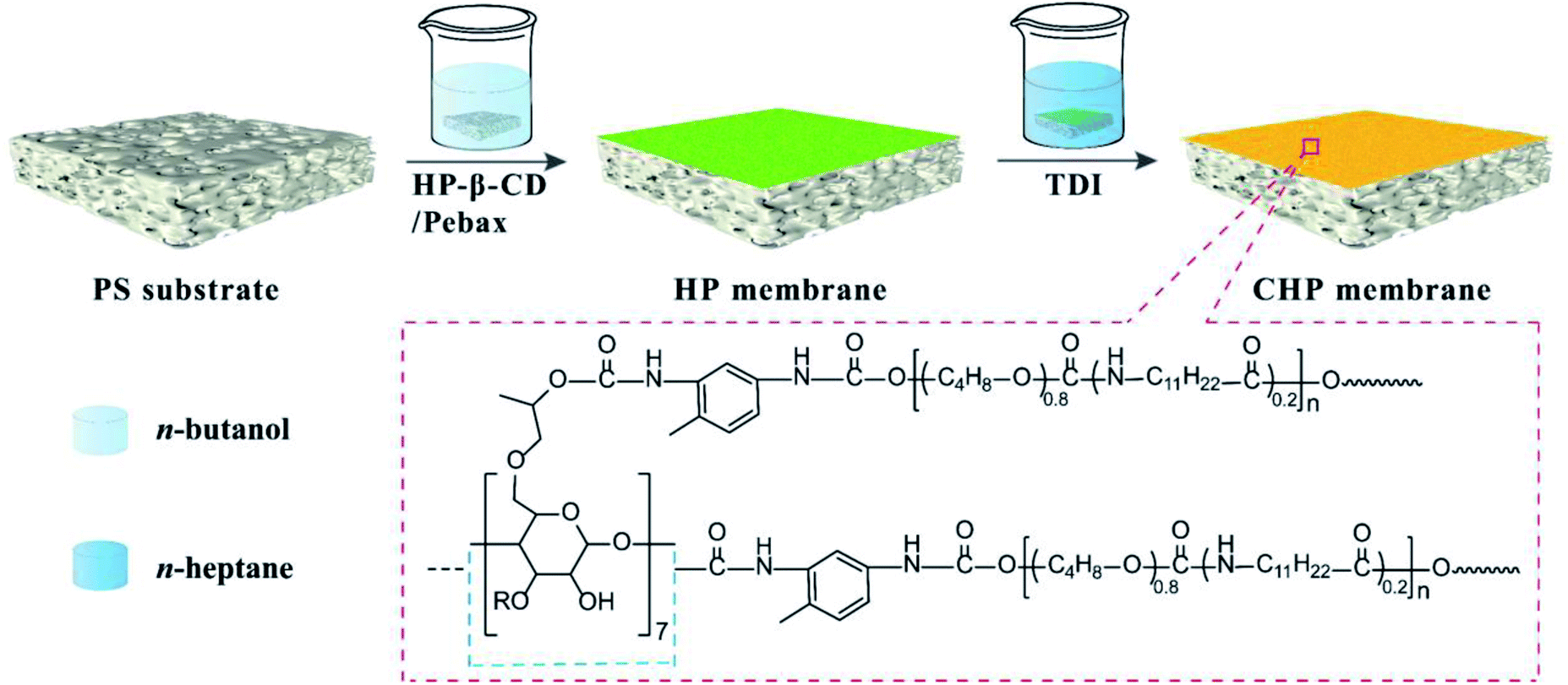
Consequently, in this work, HP-β-CD was incorporated into the Pebax layers on PS substrate and then crosslinked by TDI to form a nanocavity-contained HP-β-CD/Pebax (CHP) OSN membrane (Scheme 1). By adjusting the initial concentration (x) of HP-β-CD and the crosslinking reaction time (y), the composite, intrinsically microporous structure and surface morphology of CHPx–y (x = 0, 0.25, 0.5, 0.75; y = 5, 10, 15) membranes could be manipulated. By measuring the OSN performance of CHPx–y membranes for Evans blue and other dyes in methanol solution, CHP0.5–10 membrane was found to be the optimal membrane and displayed a high methanol permeance of 8.7 L per (m2 h bar), high dye rejection (>96%), and high stability (336 h continuous running), due to its intrinsically microporous structure and surface morphology. This work has inspired our further exploration of cyclodextrins and other macrocyclic molecules in the preparation of OSN membranes. The present work also provides a promising strategy to fabricate state-of-the-art membranes for the efficient separation of organic solvent for reclamation and for the removal of organic pollutants.
 |
| | Scheme 1 Schematic of the preparation of the crosslinked CHP membrane. | |
2 Experimental section
2.1 Materials and reagents
HP-β-CD was purchased from Shandong Binzhou Zhiyuan Biotechnology Co. Ltd. (Shandong, China). Pebax 2533 was commercially supplied by Arkema Inc. (France). TDI and n-heptane were obtained from Fuchen Chemical Reagent Co. Ltd. (Tianjin, China). Evans blue (EB), methyl blue (MB), Congo red (CR), acid fuchsin (AF), Eriochrome black T (EBT), and rhodamine B (RB) were purchased from Sigma-Aldrich (USA). Absolute ethanol, methanol, n-butanol, cyclohexane, and n-hexane were provided by Tianjin Kermel Chemistry Co., Ltd. (Tianjin, China). The commercial PS ultrafiltration membrane with a molecular weight cut-off (MWCO) of 2 × 10⁵ kDa was provided by Beijing Separate Equipment Co. Ltd. (Beijing, China) and used as a substrate membrane to fabricate the OSN membranes. Before being used, the PS substrate membrane was soaked in anhydrous ethanol for 24 h and dried naturally at room temperature. Deionized (DI) water (18.25 MΩ cm) was used throughout all the experiments.
2.2 Fabrication of the crosslinked HP-β-CD/Pebax (CHP) OSN membranes
The fabrication process of the CHP OSN membrane is depicted in Scheme 1. Briefly, Pebax 2533 in n-butanol was stirred at 70 °C for 4 h to prepare 1.0 wt% Pebax 2533 n-butanol solution. HP-β-CD powder with 0.25, 0.5, and 0.75 wt% to the total mass was then added into the Pebax solution at 70 °C under stirring to form a homogeneous and transparent solution. Subsequently, a well-cleaned PS membrane substrate was immersed into the HP-β-CD and Pebax in n-butanol solution for 3 min. This was then taken out and dried at room temperature to obtain the HP-β-CD/Pebax (HP) membrane on PS substrate. For the crosslinking reaction, the HP membrane was immersed into a 1.0 wt% TDI of n-heptane solution at room temperature for 5–15 min. After being taken out and dried, the crosslinked HP-β-CD/Pebax (CHP) membrane was obtained. Depending on the concentration (x) of HP-β-CD and the crosslinking reaction time (y) used, the obtained membranes were denoted as CHPx–y (x = 0, 0.25, 0.5, 0.75, y = 5, 10, 15).
2.3 Characterizations
The surface chemical compositions of the as-prepared membranes were characterized by Fourier transform infrared (FTIR) spectroscopy (Vertex-70, Bruker, Germany) and X-ray photoelectron spectrometry (XPS, Thermo Escalab 250, USA). The surface and cross-sectional morphologies of the membranes were imaged by field-emission scanning electron microscopy (SEM, SU8020, Japan). The surface roughness of the membranes was analyzed by atomic force microscopy (AFM, PicoScanTM2500, Agilent, USA) at 1 × 1 μm. The water contact angle (WCA) of the membranes was measured using a contact angle meter (DSA-100, Kruss, Germany).
2.4 OSN performance
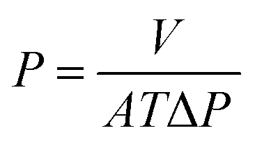
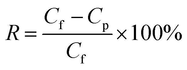
The OSN performance was measured using self-made cross-flow filtration equipment with an effective membrane area of 22 cm2. During the testing process, the membranes were pre-compacted at 4.0 bar for 3 h to reach a steady state, and then the OSN performance was tested at every 30 min interval. The permeance (P) and rejection rate (R) were calculated according to the following equations.| |
 | (1) |
where V is the permeate volume (L), A is the effective area of the membrane (m2), T is the filtration time, and ΔP is the operating pressure (bar).| |
 | (2) |
where Cf and Cp are the concentrations of the feed and permeate solution, respectively. The concentration of the dye feed solution was 10 ppm, while the concentration of the permeate solution was detected by a UV-vis spectrophotometer (UV-3200, Mapada, Shanghai, China).
3 Results and discussion
3.1 Structure and morphologies of the membranes
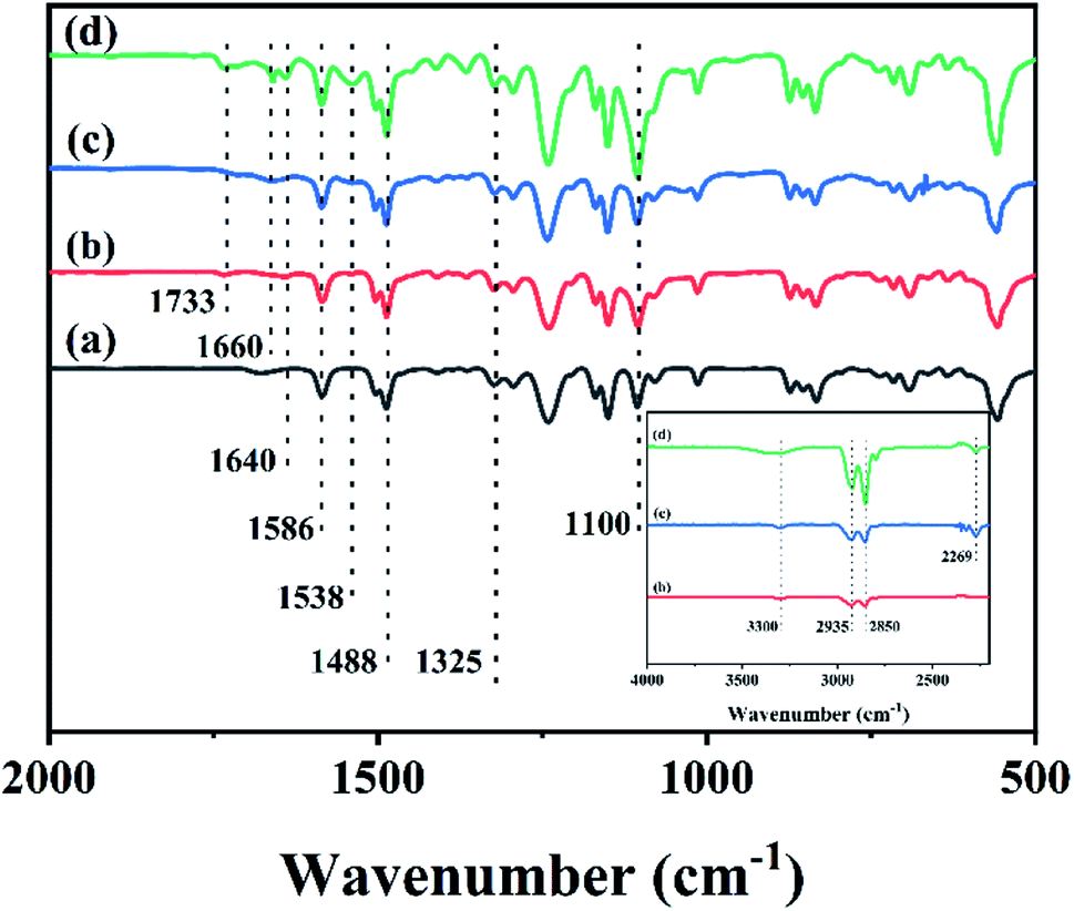
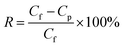
The FTIR spectra of different membranes including the PS substrate, Pebax 2533 membrane, and CHPx–10 (x = 0, 0.75) are shown in Fig. 1 and S1.† The FTIR spectrum of the PS substrate in Fig. 1a exhibited peaks at 1586 and 1488 cm−1, which were assigned to the stretching vibration of C![[double bond, length as m-dash]](https://www.rsc.org/images/entities/char_e001.gif) C from the aromatic ring and the bending and scissoring of C–H bonds from –CH(CH3)2 groups, respectively.48 The peak at 1325 cm−1 belonged to the characteristic vibration of a sulfone group from PS. The Pebax 2533 membrane on the PS substrate without TDI crosslinking (Fig. 1b) displayed a series of peaks at 1100 cm−1 (–C–O–C– stretching), 1538 cm−1 (bending of N–H in PA), 1640 cm−1 (stretching of –CO in H–N–CO), 1733 cm−1 (stretching of –CO in PA), 2850 cm−1 and 2935 cm−1 (–C–H bending), and 3300 cm−1 (stretching of N–H in PA) (inset, Fig. 1).26,27,49–51 Comparatively, after being crosslinked by TDI, the FTIR spectrum of the CHP0–10 membrane without HP-β-CD (Fig. 1c) exhibited a shift in the tiny peak of Pebax at 1640 cm−1 in Fig. 1b to 1660 cm−1, implying that the conjugation of the benzene ring of TDI would enhance the electron-donating ability of H–N–CO groups, leading to the spectral blue-shift. The signal at 2269 cm−1 was assigned to the –NCO group of TDI.26 After the incorporation of HP-β-CD into Pebax and following crosslinking with TDI, the spectrum of the CHP0.75–10 membrane obtained (Fig. 1d) showed that the peak at 1100 cm−1 assigned to C–O–C group was intensified, due to introduction of more C–O–C groups from HP-β-CD.44,45 Note that the intensity of the peak at 1660 cm−1 was slightly increased, but the peak at 2269 cm−1 attributed to –NCO bond of TDI was decreased, indicating the further crosslinking reaction between TDI and both Pebax as well as HP-β-CD. These results confirmed the formation of the crosslinked HP-β-CD/Pebax (CHP) layer on the PS substrate.
C from the aromatic ring and the bending and scissoring of C–H bonds from –CH(CH3)2 groups, respectively.48 The peak at 1325 cm−1 belonged to the characteristic vibration of a sulfone group from PS. The Pebax 2533 membrane on the PS substrate without TDI crosslinking (Fig. 1b) displayed a series of peaks at 1100 cm−1 (–C–O–C– stretching), 1538 cm−1 (bending of N–H in PA), 1640 cm−1 (stretching of –CO in H–N–CO), 1733 cm−1 (stretching of –CO in PA), 2850 cm−1 and 2935 cm−1 (–C–H bending), and 3300 cm−1 (stretching of N–H in PA) (inset, Fig. 1).26,27,49–51 Comparatively, after being crosslinked by TDI, the FTIR spectrum of the CHP0–10 membrane without HP-β-CD (Fig. 1c) exhibited a shift in the tiny peak of Pebax at 1640 cm−1 in Fig. 1b to 1660 cm−1, implying that the conjugation of the benzene ring of TDI would enhance the electron-donating ability of H–N–CO groups, leading to the spectral blue-shift. The signal at 2269 cm−1 was assigned to the –NCO group of TDI.26 After the incorporation of HP-β-CD into Pebax and following crosslinking with TDI, the spectrum of the CHP0.75–10 membrane obtained (Fig. 1d) showed that the peak at 1100 cm−1 assigned to C–O–C group was intensified, due to introduction of more C–O–C groups from HP-β-CD.44,45 Note that the intensity of the peak at 1660 cm−1 was slightly increased, but the peak at 2269 cm−1 attributed to –NCO bond of TDI was decreased, indicating the further crosslinking reaction between TDI and both Pebax as well as HP-β-CD. These results confirmed the formation of the crosslinked HP-β-CD/Pebax (CHP) layer on the PS substrate.
 |
| | Fig. 1 FTIR spectra for the (a) PS substrate, (b) Pebax 2533 membrane, (c) CHP0–10 membrane and (d) CHP0.75–10 membrane. | |
In addition, FTIR spectra on the reverse side of CHP0.5–10 membrane were also measured. As shown in Fig. S2 (ESI),† it was clear that the IR spectrum of CHP0.5–10 was consistent with the PS substrate. The characteristic absorption peaks of C–O–C at 1100 cm−1 from HP-β-CD and H–N–CO at 1640 cm−1 from Pebax 2533 could not be found in the FTIR spectra of the reverse side of the CHP0.5–10 membrane, clearly verifying that a selective layer mainly existed on the front side of the PS substrate.
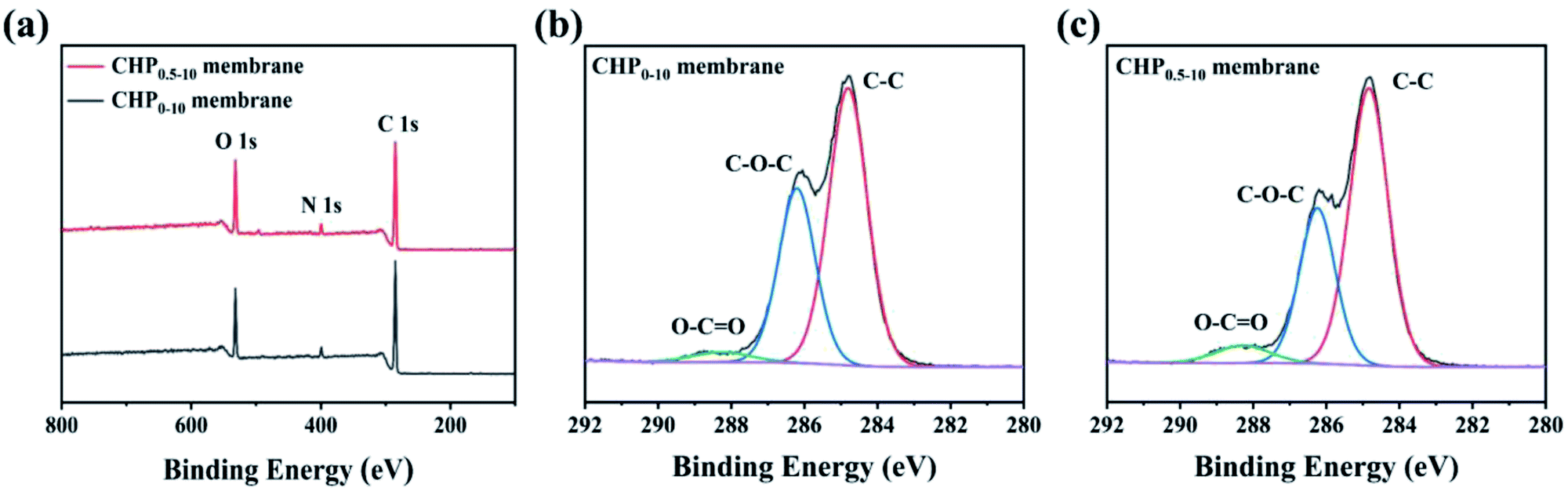
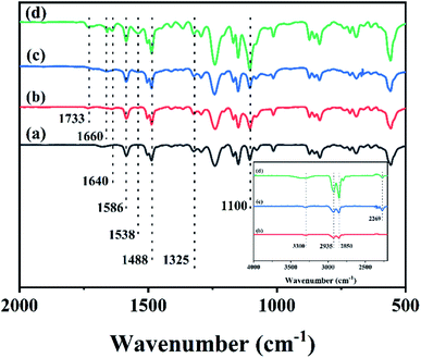
To further explicate the elemental compositions of the CHP0–10 and CHP0.5–10 membranes, XPS analysis was performed as shown in Fig. 2. As can be seen in Fig. 2a, both membranes presented three peaks at 531.92 (O 1s), 399.17 (N 1s), and 284.94 eV (C 1s). The elemental atomic percentages of carbon (C), oxygen (O), and nitrogen (N) on the membrane surface listed in Table 1 show that the O/N ratio increased from 3.96% for the CHP0–10 membrane to 4.25% for the CHP0.5–10 membrane. The increase in the O/N ratio of the HP-β-CD-incorporated membranes can be attributed to the high oxygen content of HP-β-CD (45.4 wt%). This indicated that HP-β-CD had been successfully incorporated into the Pebax selective layer. According to the high-resolution C 1s XPS spectra of the membranes (Fig. 2b, c and Table S1†), the proportion of O–CO from polyurethane was remarkably increased from 3.37% to 5.54%. Also, the high-resolution N 1s and O 1s XPS spectra were further analyzed. As can be seen in Fig. S3a and b,† the N 1s peak from the high-resolution XPS was deconvoluted into three peaks at 397.5, 399.4, and 399.8 eV, which were attributed to the corresponding –NCO and Calkyl–NH–CO and Cbenzyl–NH–CO groups, respectively.52 It is obvious that the N atom was bonded to three different C centres from the benzene ring, carbonyl, and saturated alkyl groups, respectively, showing slightly different binding energies. The proportion of Cbenzyl–NH–CO from polyurethane increased from 53.99% in the CHP0–10 membrane to 72.14% in the CHP0.5–10 membrane. Similarly, the high-resolution O 1s XPS spectra (Fig. S3c and d†) clearly showed two peaks at 533.0 and 534.7 eV, which were attributed to the binding energy of CO and C–O, respectively. Due to the addition of HP-β-CD, the proportion of CO bonds formed by the crosslinking reaction of TDI with hydroxyl groups on the membrane surface increased from 6.12% for the CHP0–10 membranes to 10.74% for the CHP0.5–10 membranes. All these results show that more TDI molecules participated in the crosslinking reaction to form the polyurethane structure with the incorporation of HP-β-CD, further verifying the successful crosslinking of TDI with HP-β-CD and Pebax.
 |
| | Fig. 2 (a) XPS survey spectra, (b and c) high-resolution C 1s spectra of the CHP0–10 and CHP0.5–10 membranes, respectively. | |
Table 1 XPS results of the CHP0–10 and CHP0.5–10 membranes
| Membrane |
C (%) |
O (%) |
N (%) |
O/N (%) |
| CHP0–10 |
77.63 |
17.86 |
4.51 |
3.96 |
| CHP0.5–10 |
76.26 |
19.22 |
4.52 |
4.25 |
The surface morphologies of the CHPx–10 (x = 0, 0.25, 0.5, 0.75) OSN membranes are shown in Fig. 3a. It was noted that the CHP0–10 membrane displayed a uniform textured surface, due to the nanoscale arrangement between the “soft” phase (polyether) and the glassy phase (polyamide) of Pebax caused by the crosslinking.53 After the incorporation of 0.25 wt% HP-β-CD, the textural morphology of the CHP0.25–10 membrane surface became more obvious. The texture image then became more compact with further increasing the HP-β-CD content to 0.50 and 0.75 wt% (Fig. 3a). The corresponding cross-sectional SEM images (Fig. 3b) indicated that the thickness of the CHP0–10 membrane without HP-β-CD was ∼0.27 μm; however, with increasing the HP-β-CD content from 0.25 to 0.75 wt%, the thickness of the CHPx–10 (x = 0.25, 0.5, 0.75) membranes was gradually elevated to ∼0.97, ∼3.92, and ∼3.99 μm, respectively. This result was mainly attributed to the host–guest interaction of HP-β-CD with the polyether chains and hydrogen bond interaction with Pebax.54 This would lead to an increased microphase separation, leading to a more obvious texture morphology (Fig. 3a).55 In addition, the crosslinking reaction would occur not only between TDI and Pebax but also between TDI and HP-β-CD, which was verified by the FTIR spectra in Fig. 1 and XPS results in Fig. 2. With increasing the HP-β-CD content, strong hydrogen bond interactions and crosslinking reactions induced the formation of a more compact layer of membranes (Fig. 3a). Hence, the thickness of the membranes CHPx–10 (x = 0.25, 0.5, 0.75) increased with the corresponding increase in the HP-β-CD concentration in the casting solution.
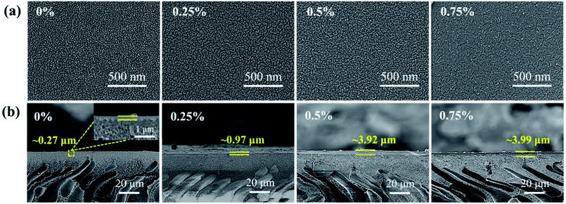 |
| | Fig. 3 (a) Surface and (b) cross-sectional SEM images of the CHP0–10, CHP0.25–10, CHP0.5–10, and CHP0.75–10 membranes. | |
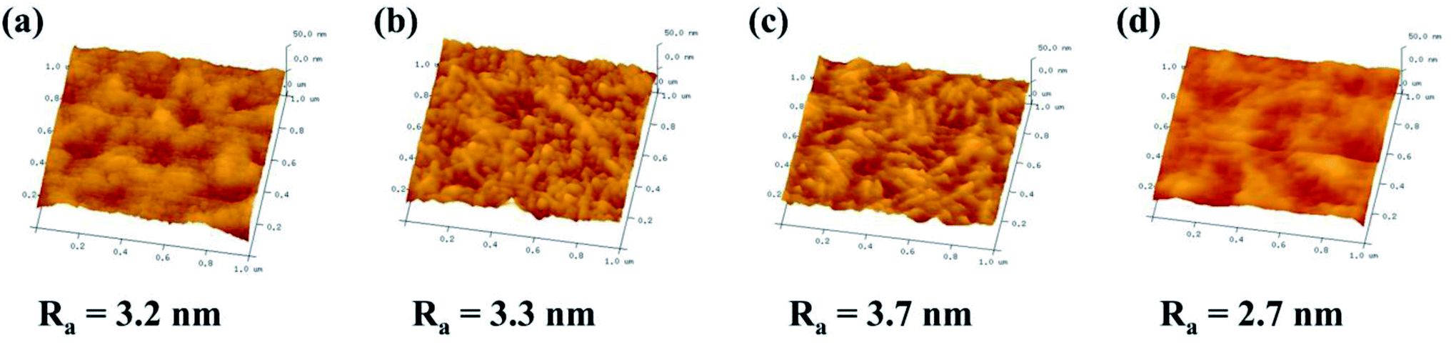
The three-dimensional (3D) topology of the CHPx–10 (x = 0, 0.25, 0.5, 0.75) membrane surface was further probed by AFM to detect the surface roughness (Ra). As shown in Fig. 4, the surface roughness displayed an initial increase and then decreased with the variation in the HP-β-CD amount. With increasing HP-β-CD from 0 to 0.50 wt%, the Ra value of the CHPx–10 (x = 0, 0.25, 0.5) membranes increased from 3.2 to 3.7 nm due to the promoted microphase separation between the Pebax segments and HP-β-CD crosslinked by TDI. When the HP-β-CD content was increased to 0.75%, the Ra value of the CHP0.75–10 membrane dropped sharply to 2.7 nm. This was probably due to HP-β-CD being relatively compatible with polyether chains and having a strong interaction with Pebax via hydrogen bonds, which drove the local regular arrangement of polymer chains,54 leading to the formation of a more smooth surface with reduced roughness.
 |
| | Fig. 4 AFM images of the: (a) CHP0–10, (b) CHP0.25–10, (c) CHP0.5–10, and (d) CHP0.75–10 membranes. | |
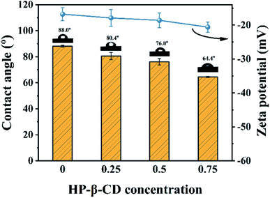
The surface wettability and electrical charges of the fabricated membranes were respectively characterized by their water contact angles (WCA) and zeta potential. As shown in Fig. 5, the WCA of the CHP0–10 membrane was around 88.0° due to the fewer hydroxyl groups on the membrane surface through the crosslinking. However, with increasing the HP-β-CD amount, the WCA decreased from 80.4° for the CHP0.25–10 membrane to 76.0° for the CHP0.5–10 membrane, and to 64.4° for the CHP0.75–10 membrane, indicating the significant improvement of the hydrophilicity of the CHPx–10 membrane, due to the existence of a great number of hydroxyl groups from HP-β-CD in the membrane. Moreover, with increasing the HP-β-CD content, the zeta potential of the membranes in Fig. 5 also gradually decreased from −16.8 mV for the CHP0–10 membrane to −18.6 mV for the CHP0.5–10 membrane and −20.6 mV for the CHP0.75–10 membrane, due to the introduction of more HP-β-CD, which would introduce more hydroxy groups into the membrane, leading to a more hydrophilic and more negative surface. Note that even when the crosslinking degree increased (TDI simultaneously reacted with hydroxyl groups from HP-β-CD and Pebax 2533), all the hydroxyl groups from HP-β-CD could not be completely consumed, and a great number of hydroxyl groups were still preserved in the membrane surface. As a result, the improvements in the hydrophilicity and surface electronegativity of the CHP0.75–10 membrane directly led to a remarkably declined WCA and a low negative zeta potential.
 |
| | Fig. 5 Surface wettability and zeta potential of the CHPx–10 membranes (x = 0, 0.25, 0.5, 0.75). | |
3.2 Optimization of the CHP membranes
The HP-β-CD concentration (x) and crosslinking time (y) of TDI were investigated to optimize the OSN performances of the CHP membranes. When the crosslinking reaction time was 10 min, the separation properties of the CHPx–10 membranes prepared with different HP-β-CD concentrations were tested using 10 ppm EB methanol solution at 20 °C under 4.0 bar. As shown in Fig. 6a, the methanol permeance of the CHP0–10 membrane was 5.1 L per (m2 h bar), with a rejection of 93%. When the mass ratio of HP-β-CD was 0.5 wt%, the CHP0.5–10 membrane exhibited a 96% rejection rate accompanied with the highest methanol permeance of 8.9 L per (m2 h bar). These results indicated that the incorporation of HP-β-CD into Pebax was conducive to the enhancement of the membrane rejection and methanol permeance. However, when further increasing the HP-β-CD mass ratio to 0.75 wt%, the methanol permeance of the CHP0.75–10 membrane decreased and the corresponding rejection rate increased. The reason for this was probably due to the more compact selective layer (Fig. 3a) and less rough membrane surface (Fig. 4d), leading to a decreased methanol permeability. The enhanced rejection of the CHPx–10 membranes could be assigned to the increased surface negatively charge (Fig. 5), which correspondingly increased the electrostatic repulsion between the solute and the membrane surface. In other words, the Donnan exclusion effects between the surface and the charged molecule played an important role. The high permeability of the as-prepared CHPx–10 membranes could be ascribed to the surface properties of the top selective layer and the inner cavity size of the membrane formed by the appropriate incorporation of HP-β-CD. First, the improvement of the surface hydrophilicity with increasing the HP-β-CD content, as shown in Fig. 5, was beneficial for polar solvent transport through the membrane.56 Second, the inner cavity size of HP-β-CD as a nanochannel on the membrane directly influenced the transport of methanol in the active layer.44 Third, increasing the surface roughness further increased the methanol permeance; thus, an increase in the methanol permeance was achieved. Though the increase in the thickness of the active layer, as shown in Fig. 4b, will increase the transport resistance, the limited increment was insufficient to hinder the permeance improvement. Therefore, the permeance of the CHPx–10 membranes showed an improvement under the combined effects of roughness, hydrophilicity, and the HP-β-CD content.
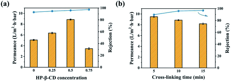 |
| | Fig. 6 OSN performances of the: (a) CHPx–10 membranes (x = 0, 0.25, 0.5, 0.75) and (b) CHP0.5–y membranes (y = 5, 10, 15) for EB in methanol solution. | |
When the mass ratio of HP-β-CD was fixed at 0.5 wt%, a series of CHP0.5–y membranes were prepared by controlling the crosslinking reaction times from 5 min to 15 min. The OSN performances of the resulting CHP0.5–y membranes were investigated as shown in Fig. 6b. It was found that a longer reaction time led to a high rejection rate with a low permeance, possibly due to a high crosslinking degree on the membrane.52 XPS spectroscopy was used to demonstrate the variation of the crosslinking degree of the CHP0.5–5 and CHP0.5–15 membranes.52 As shown in Fig. S4,† the high-resolution C 1s XPS spectra clearly showed that the proportion (5.97%) of O–CO species in the CHP0.5–15 membrane was higher than 3.40% in the CHP0.5–5 membrane, indicating a gradual increase in the degree of crosslinking with increasing the crosslinking time. Therefore, when the crosslinking time increased from 5 to 15 min, the methanol permeance of the membrane markedly decreased from 9.5 to 8.2 L per (m2 h bar), while the rejection rate increased from 89.76% to 96.87%. Based on the above-mentioned results, HP-β-CD concentration of 0.5 wt% and the crosslinking time of 10 min were optimal conditions for the preparation of the CHP0.5–10 membrane.
3.3 Separation performance of the CHP0.5–10 membrane
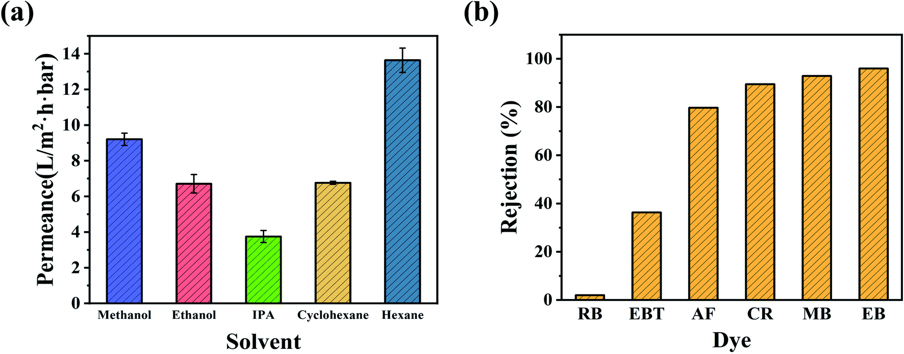
The OSN permeances of polar and nonpolar solvents, including methanol (MeOH), ethanol (EtOH), isopropanol (IPA), cyclohexane, and n-hexane, were further investigated using the CHP0.5–10 membrane at ambient conditions. As can be seen from Fig. 7a, the membrane exhibited considerable high permeance for nonpolar solvents, such as a cyclohexane permeance of 6.8 L per (m2 h bar) and n-hexane permeance of 13.6 L per (m2 h bar), meanwhile, for polar solvents, the permeance in order was: MeOH (9.2 L per (m2 h bar)) > EtOH (6.7 L per (m2 h bar)) > IPA (3.8 L per (m2 h bar)). The difference in permeance might be related to the solvent's intrinsic properties, such as viscosity, kinetic diameter, and solubility parameter, as shown in Table S2.† Generally, solvent molecules with a lower viscosity, smaller molar diameter, and solubility parameters similar to the separation layer can more easily penetrate through membranes. Also, the permeance of the hydrophobic membrane increased as the polarity of the solvent decreased, while the permeance of the hydrophilic membrane decreased as the polarity of the solvent decreased.56 Although the as-prepared CHP membranes were hydrophilic (Fig. 5), the high permeance for cyclohexane and n-hexane was mainly due to the hydrophobic inner cavity of HP-β-CD having an excellent affinity towards cyclohexane and n-hexane.44 However, the permeance of n-hexane was higher than that of cyclohexane, which was primarily attributed to the viscosity of n-hexane (0.29 (10−3 Pa s)) being much lower than that of cyclohexane (0.94 (10−3 Pa s)). For polar solvents, the kinetic diameters, following the trend of MeOH (0.51 nm) < EtOH (0.57 nm) < IPA (0.62 nm), was exactly the opposite order from their permeance. This may be due to the hydroxyl (–OH) groups on the exterior of HP-β-CD cavities forming a relatively hydrophilic space between HP-β-CD and Pebax with a high affinity towards polar organic solvents. Another important reason is that the cavity size of β-CD (0.60 nm) could allow MeOH (0.51 nm) and EtOH (0.57 nm) to migrate across but not IPA (0.62 nm),45 resulting in a high permeance for MeOH and EtOH.
 |
| | Fig. 7 (a) Nanofiltration performance of polar and nonpolar solvents for the CHP0.5–10 membrane. (b) Rejection of dyes with different molecular weights through the CHP0.5–10 membrane. | |
Furthermore, the separation performance of the CHP0.5–10 membrane was further investigated by MeOH solutions of different dyes, including Eriochrome black T (EBT), rhodamine B (RB), acid fuchsin (AF), Congo red (CR), methyl blue (MB), and Evans blue (EB). Table S3 (ESI)† illustrates the chemical structures and molecular weights of these dyes. As shown in Fig. 7b, the rejection order of the negatively charged dyes was EB (96.0%, Mw = 961 Da) > MB (92.9%, Mw = 800 Da) > CR (89.5%, Mw = 697 Da) > AF (79.7%, Mw = 585 Da) > EBT (36.3%, Mw = 461 Da). This indicated that the rejection of the CHP0.5–10 membrane generally increased with the increasing molecular weight of dyes. However, the rejection of RB (around 2.0%) was lower than that of EBT, although the molecular weight of RB (Mw = 479 Da) was larger than that of EBT (Mw = 461 Da, 36.3%). The low rejection of RB might be related to the positive charge of RB in methanol,57,58 which can more easily pass through the membrane. According to the electric charges of the dyes and zeta potential of the CHP membrane in Fig. 5, there was a Donnan effect between the negatively charged membrane and dye molecules. Thus, the rejection mechanism of the prepared membrane for dye molecules was mainly attributed to the molecular size effect and the Donnan effect. Fig. S5† further depicts the separation performance of the CHP0.5–10 membrane for EB in EtOH (97.0%) and IPA (97.1%). These high rejection rates indicated that the CHP0.5–10 membrane has excellent potential for organic solvent nanofiltration.
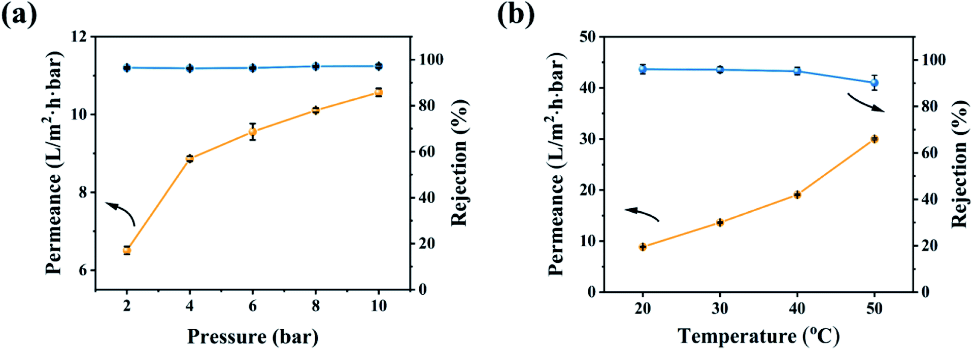
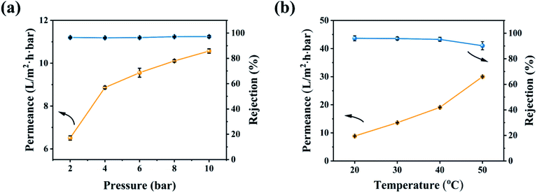
The effect of the operating conditions on the OSN performance was further investigated in Fig. 8. With increasing the operating pressure, the permeability of the CHP0.5–10 membrane increased and EB rejection was slightly changed (Fig. 8a), due to the increment of the operating pressure reinforcing the driving force of the membrane and thereby increasing the permeability.59 In general, an increase in pressure will cause the pores of the OSN membrane to shrink,7,59 so the basically unchanged rejection rate showed that the CHP0.5–10 membrane had excellent stability in a range of 2.0–10.0 bar. In addition, the increasing operating temperature could also increase the permeability (Fig. 8b). This behaviour may be explained by an enhancement of the methanol mass transfer coefficient,60 thanks to the decrease in the temperature-dependent viscosity of the methanol solution. Moreover, with increasing the operating temperature, a dilatation in the pore sizes occurred, which facilitated the transport of solutes through the membrane and reduced the concentrations in the membrane pores and on the membrane surfaces.60,61
 |
| | Fig. 8 OSN performance of the CHP0.5–10 membrane for EB in methanol solution under (a) various operating pressures and (b) different temperatures. | |
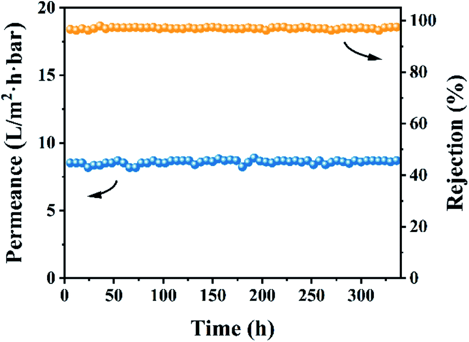
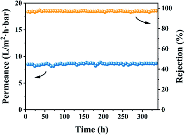
Based on the above-mentioned investigations, a comparison of the OSN performances among the optimal CHP0.5–10 membrane and the previously reported membranes62 is presented in Table 2. The results indicated that the CHP0.5–10 membranes were markedly superior to those in previous reports, revealing the outstanding effect of HP-β-CD in preparing an OSN membrane for potential application in the decolorization of textile dyeing industry effluent. Bruggen et al. reported previously that when the membrane was immersed in an organic solvent, the polymer chains might migrate on the membrane top layer, causing a change in the size and distribution of the membrane pores, thereby reducing the rejection rate.56 Therefore, the long-term stability of the membrane was evaluated in 10 ppm EB methanol solution for consecutive running of 336 h. As shown in Fig. 9, the CHP0.5–10 membrane still maintained a high rejection of about 96.0% and a high permeance of about 8.7 L per (m2 h bar) during the test period, revealing the superior stability of the membrane for EB in methanol solution.
Table 2 Comparison of the OSN performances among the crosslinked HP-β-CD/Pebax (CHP0.5–10) membrane and some reported OSN membranesa62
| Membrane |
Solvent |
Solute |
Solvent permeance (L per m2 per h per bar) |
Rejection (%) |
Reference |
| EB: Evans blue; BB: brilliant blue; RBB: Remazol brilliant blue; MO: methyl orange; MB: methyl blue. |
| CHP0.5–10 |
Methanol |
EB |
9.2 |
96.0 |
This work |
| Ethanol |
6.7 |
97.0 |
| Isopropanol |
3.8 |
97.1 |
| PBI/polyester support |
Ethanol |
RBB |
3.69 |
∼100 |
25 and 62 |
| Pebax 1657/GO/PAN |
Ethanol |
BB |
1.9 ± 0.012 |
95 |
26 and 62 |
| Pebax 2533/PS |
Methanol |
EB |
7.2 |
91.6 |
27 and 62 |
| β-CD-TMC/Matrimid |
Ethanol |
RBB |
3.1 |
95.7 |
44 and 62 |
| PEI/β-CD/PAN |
Isopropanol |
PEG 1000 |
2.2 |
>93 |
45 and 62 |
| β-CD-TC/PAN |
Methanol |
MO |
5.8 |
93 |
47 and 62 |
| PIM-1/PAN |
Ethanol |
Tetrazolium blue chloride |
4.3 |
∼92 |
62 and 63 |
| PDA/P84 |
Ethanol |
MB |
∼0.8–0.9 |
∼99 |
62 and 64 |
| PDA/β-CD/P84 |
Ethanol |
MB |
14.9 |
97.6 |
62 and 65 |
| Polyamide 6 hollow fibre |
Methanol |
VB-12 |
0.27 |
96.3 |
62 and 66 |
| PDA/PAN |
Methanol |
1.58–5.4 nm Au nanoparticles |
∼1.3 |
97.5 |
62 and 67 |
| TTSBI-TMC/cross-linked P84 co-polyimide/PP support |
Methanol |
Crystal violet |
6.0 |
98.7 |
62 and 68 |
 |
| | Fig. 9 Stability performance of the CHP0.5–10 membrane for EB in methanol solution. | |
4 Conclusions
In summary, HP-β-CD was successfully incorporated into the Pebax layer on the PS support, and further polymerized with TDI to prepare a crosslinked HP-β-CD/Pebax (CHP) membrane. By adjusting the initial concentration (x) of HP-β-CD and the crosslinking reaction time (y), the composite, structure, and surface morphology of the CHPx–y (x = 0, 0.25, 0.5, 0.75; y = 5, 10, 15) membranes obtained could be controlled, which was performed by the competitively interfacial crosslinking polymerizations of TDI with both HP-β-CD and Pebax 2533. Testing the OSN performance of the obtained CHPx–y membranes confirmed that the CHP0.5–10 membrane was an optimal membrane and indicated a high methanol permeance of 8.7 L per (m2 h bar), high rejection for dyes (96.0% for EB, 92.9% for MB), and high stability (at least consecutive running for 336 h) in methanol solution, thanks to the intrinsic microporous structure fabricated by the incorporation of HP-β-CD into the 3D networks of the membrane. Especially, the CHP0.5–10 membrane exhibited a higher rejection rate for the negatively charged dye EBT with a molecular weight of 461 Da compared to that of the positively charged dye RB with a molecular weight of 479 Da, revealing the excellent rejection rate of the resulting CHP0.5–10 membrane for the negatively charged solute. This work inspires the further development of cyclodextrins and other macrocyclic molecules for the preparation of OSN membranes and provides a promising strategy to fabricate state-of-the-art membranes for the efficient separation of solvents for reclamation, as well as organic pollutants removal and heavy metals, and drug purification.
Conflicts of interest
There are no conflicts to declare.
Acknowledgements
This work was financially supported by the National Natural Science Foundation of China (21878003, 22178007) and the Seed Foundation Project of International Cooperation from Beijing University of Technology (2021-A11). Also, the helpful and valuable discussion from Dr Wenhai Zhang is well appreciated.
Notes and references
- M. H. D. A. Farahani and T.-S. Chung, Chem. Eng. J., 2018, 345, 174–185 CrossRef.
- C. Jiménez-González, A. D. Curzons, D. J. Constable and V. L. Cunningham, Int. J. Life Cycle Assess., 2004, 9, 114–121 CrossRef.
- C. S. Slater, M. J. Savelski, W. A. Carole and D. J. Constable, Green Chemistry in the Pharmaceutical Industry, ed. P. J. Dunn, A. S. Wells and M. T. Williams, Wiley-VCH Verlag GmbH & Co. KGaA, Weinheim, Germany, 2010, ch. 3, pp. 49–82 Search PubMed.
- V. R. Veleva, B. W. Cue and S. Todorova, ACS Sustainable Chem. Eng., 2017, 6, 2–14 CrossRef.
- D. S. Sholl and R. P. Lively, Nature, 2016, 532, 435 CrossRef.
- S. Hermans, H. Mariën, C. Van Goethem and I. F. J. Vankelecom, Curr. Opin. Chem. Eng., 2015, 8, 45–54 CrossRef.
- P. Marchetti, M. F. Jimenez Solomon, G. Szekely and A. G. Livingston, Chem. Rev., 2014, 114, 10735–10806 CrossRef CAS.
- A. K. Hołda, B. Aernouts, W. Saeys and I. F. J. Vankelecom, J. Membr. Sci., 2013, 442, 196–205 CrossRef.
- J. da Silva Burgal, L. G. Peeva, S. Kumbharkar and A. Livingston, J. Membr. Sci., 2015, 479, 105–116 CrossRef CAS.
- K. Hendrix, M. Van Eynde, G. Koeckelberghs and I. F. J. Vankelecom, J. Membr. Sci., 2013, 447, 212–221 CrossRef CAS.
- Z. F. Gao, G. M. Shi, Y. Cui and T.-S. Chung, J. Membr. Sci., 2018, 565, 169–178 CrossRef CAS.
- M. F. J. Solomon, Y. Bhole and A. G. Livingston, J. Membr. Sci., 2012, 423–424, 371–382 CrossRef.
- Y. H. S. Toh, F. W. Lim and A. G. Livingston, J. Membr. Sci., 2007, 301, 3–10 CrossRef CAS.
- K. Vanherck, P. Vandezande, S. O. Aldea and I. F. J. Vankelecom, J. Membr. Sci., 2008, 320, 468–476 CrossRef CAS.
- S. H. Park, Y. J. Kim, S. J. Kwon, M. G. Shin, S. E. Nam, Y. H. Cho, Y. I. Park, J. F. Kim and J. H. Lee, ACS Appl. Mater. Interfaces, 2018, 10, 44050–44058 CrossRef CAS PubMed.
- L. E. Gevers, I. F. Vankelecom and P. A. Jacobs, Chem. Commun., 2005, 2500–2502 RSC.
- A. Karimi, A. Khataee, M. Safarpour and V. Vatanpour, Sep. Purif. Technol., 2020, 237, 11635 CrossRef.
- X. Li, S. De Feyter, D. Chen, S. Aldea, P. Vandezande, F. Du Prez and I. F. Vankelecom, Chem. Mater., 2008, 20, 3876–3883 CrossRef CAS.
- C. Linder, M. Perry, M. Nemas and R. Katraro, US Pat., 5039421, 1991-8-13 Search PubMed.
- N. W. Oh, J. Jegal and K. H. Lee, J. Appl. Polym. Sci., 2001, 80, 1854–1862 CrossRef CAS.
- D. Chen, S. Yu, M. Yang, D. Li and X. Li, RSC Adv., 2016, 6, 16925–16932 RSC.
- M. H. Davood, A. Farahani and T.-S. Chung, Sep. Purif. Technol., 2019, 209, 182–192 CrossRef.
- G. Székely, I. B. Valtcheva, J. F. Kim and A. G. Livingston, React. Funct. Polym., 2015, 86, 215–224 CrossRef.
- I. B. Valtcheva, P. Marchetti and A. G. Livingston, J. Membr. Sci., 2015, 493, 568–579 CrossRef CAS.
- D. Y. Xing, S. Y. Chan and T.-S. Chung, Green Chem., 2014, 16, 1383–1392 RSC.
- J. Aburabie and K.-V. Peinemann, J. Membr. Sci., 2017, 523, 264–272 CrossRef CAS.
- Z. Liu, Z. Qin, S. Cui, M. Jia, Q. An, N. Wang, Y. Liu and H. Guo, Chem. Ind. Eng. Prog., 2020, 39, 2715–2723 Search PubMed.
- M. Sforca, S. Nunes and K.-V. Peinemann, J. Membr. Sci., 1997, 135, 179–186 CrossRef CAS.
- P. Vandezande, L. E. Gevers and I. F. Vankelecom, Chem. Soc. Rev., 2008, 37, 365–405 RSC.
- R. Casadei, M. Giacinti Baschetti, M. J. Yoo, H. B. Park and L. Giorgini, Membranes, 2020, 10, 188 CrossRef CAS.
- H. Yuan, X. Liu, S. Zhang and J. Lu, Chem. Eng. Process., 2019, 144, 107632–107639 CrossRef CAS.
- N. L. Le, Y. Wang and T.-S. Chung, J. Membr. Sci., 2011, 379, 174–183 CrossRef.
- K. Liu, C.-J. Fang, Z.-Q. Li and M. Young, J. Membr. Sci., 2014, 451, 24–31 CrossRef CAS.
- A. E. Yildirim, N. D. Hilmioglu and S. Tulbentci, Desalination, 2008, 219, 14–25 CrossRef CAS.
- Y. Zhang, Z. Jiang, J. Song, J. Song, F. Pan, P. Zhang and X. Cao, Ind. Eng. Chem. Res., 2019, 58, 16911–16921 CrossRef CAS.
- R. Casadei, M. Giacinti Baschetti, B. G. Rerolle, H. B. Park and L. Giorgini, Polymer, 2021, 228, 123944 CrossRef CAS.
- M. Fakoori, A. Azdarpour, R. Abedini and B. Honarvar, Korean J. Chem. Eng., 2021, 38, 121–128 CrossRef CAS.
- J. Gao, H. Mao, H. Jin, C. Chen, A. Feldhoff and Y. Li, Microporous Mesoporous Mater., 2020, 297, 110030–110038 CrossRef.
- E. G. Estahbanati, M. Omidkhah and A. E. Amooghin, J. Ind. Eng. Chem., 2017, 51, 77–89 CrossRef.
- V. Nafisi and M. B. Hagg, ACS Appl. Mater. Interfaces, 2014, 6, 15643–15652 CrossRef CAS PubMed.
- M. S. A. Wahab and A. R. Sunarti, Int. J. Membr. Sci. Technol., 2015, 2, 78–84 CrossRef.
- P. D. Sutrisna, J. Hou, M. Y. Zulkifli, H. Li, Y. Zhang, W. Liang, D. M. D'Alessandro and V. Chen, J. Mater. Chem. A, 2018, 6, 918–931 RSC.
- W. Zhu, Y. Qin, Z. Wang, J. Zhang, R. Guo and X. Li, J. Energy Chem., 2019, 31, 1–10 CrossRef.
- J. Liu, D. Hua, Y. Zhang, S. Japip and T. S. Chung, Adv. Mater., 2018, 30, 1705933–1705939 CrossRef PubMed.
- H. Mao, H. Zhang, Y. Li, Y. Xue, F. Pei, J. Wang and J. Liu, ACS Sustainable Chem. Eng., 2015, 3, 1925–1933 CrossRef CAS.
- T. Huang, T. Puspasari, S. P. Nunes and K.-V. Peinemann, Adv. Funct. Mater., 2019, 30, 1906797–1906804 CrossRef.
- L. F. Villalobos, T. Huang and K.-V. Peinemann, Adv. Mater., 2017, 29, 1606641–1606647 CrossRef PubMed.
- Z. Yao, H. Guo, Z. Yang, W. Qing and C. Y. Tang, Desalination, 2018, 445, 115–122 CrossRef CAS.
- L. M. Gradinaru, M. Barbalata-Mandru, M. Drobota, M. Aflori, M. Spiridon, G. Gradisteanu Pircalabioru, C. Bleotu, M. Butnaru and S. Vlad, Nanomaterials, 2020, 10, 754–773 CrossRef CAS PubMed.
- J. Konieczny and K. Loos, Polymers, 2019, 11, 256–265 CrossRef.
- D. P. Nayak, A. M. Kotha, O. S. Yemul, S. Ponrathnam and R. C. Raman, Biomacromolecules, 2001, 2, 1116–1123 CrossRef CAS PubMed.
- T. Huang, B. A. Moosa, P. Hoang, J. Liu, S. Chisca, G. Zhang, M. AlYami, N. M. Khashab and S. P. Nunes, Nat. Commun., 2020, 11, 5882 CrossRef CAS PubMed.
- A. Car, C. Stropnik, W. Yave and K.-V. Peinemann, Adv. Funct. Mater., 2008, 18, 2815–2823 CrossRef CAS.
- S. Uenuma, R. Maeda, H. Yokoyama and K. Ito, Soft Matter, 2020, 16, 9035–9041 RSC.
- Y. Zhang, Y. Shen, J. Hou, Y. Zhang, W. Fam, J. Liu, T. D. Bennett and V. Chen, ACS Appl. Mater. Interfaces, 2018, 10, 20006–20013 CrossRef CAS PubMed.
- J. G. B. Van der Bruggen and C. Vandecasteele, Chem. Eng. Sci., 2002, 57, 2511–2518 CrossRef.
- B. Li, Y. Cui, S. Japip, Z. Thong and T.-S. Chung, Carbon, 2018, 130, 503–514 CrossRef CAS.
- Y. Lu, Z. Wang, W. Fang, Y. Zhu, Y. Zhang and J. Jin, Ind. Eng. Chem. Res., 2020, 59, 22533–22540 CrossRef CAS.
- W. Mickols, Z. Mai and B. van der Bruggen, Desalination, 2021, 501, 114905–114918 CrossRef CAS.
- C. F. Couto, W. G. Moravia and M. C. S. Amaral, Clean Technol. Environ. Policy, 2017, 19, 2057–2073 CrossRef CAS.
- S. R. Hosseinabadi, K. Wyns, V. Meynen, A. Buekenhoudt and B. Van der Bruggen, J. Membr. Sci., 2016, 513, 177–185 CrossRef CAS.
- G. M. Shi, Y. Feng, B. Li, H. M. Tham, J.-Y. Lai and T.-S. Chung, Prog. Polym. Sci., 2021, 123, 101470–101496 CrossRef CAS.
- J. Li, M. Zhang, W. Feng, L. Zhu and L. Zhang, J. Membr. Sci., 2020, 601, 117951–117958 CrossRef.
- Y. Xu, F. You, H. Sun and L. Shao, ACS Sustainable Chem. Eng., 2017, 5, 5520–5528 CrossRef CAS.
- Y. Zhang, H. Sun, H. Sadam, Y. Liu and L. Shao, Chem. Eng. J., 2019, 371, 535–543 CrossRef CAS.
- S. Jeon, A. Nishitani, L. Cheng, L.-F. Fang, N. Kato, T. Shintani and H. Matsuyama, RSC Adv., 2018, 8, 19879–19882 RSC.
- C. Zhang, Y. Lv, W. Z. Qiu, A. He and Z. K. Xu, ACS Appl. Mater. Interfaces, 2017, 9, 14437–14444 CrossRef CAS.
- M. F. Jimenez-Solomon, Q. Song, K. E. Jelfs, M. Munoz-Ibanez and A. G. Livingston, Nat. Mater., 2016, 15, 760–767 CrossRef CAS PubMed.
|
| This journal is © The Royal Society of Chemistry 2022 |
Click here to see how this site uses Cookies. View our privacy policy here. 
 Open Access Article
 This Open Access Article is licensed under a Creative Commons Attribution-Non Commercial 3.0 Unported Licence
 *b,
Ziyang Liua,
Yue Liu
*b,
Ziyang Liua,
Yue Liu