DOI:
10.1039/D2RA01125E
(Paper)
RSC Adv., 2022,
12, 12453-12462
Electronic, mechanical, optical and piezoelectric properties of glass-like sodium silicate (Na2SiO3) under compressive pressure
Received
20th February 2022
, Accepted 31st March 2022
First published on 25th April 2022
Abstract
The structural, mechanical, electronic, optical and piezoelectric properties of Na2SiO3 are studied under varying compressive unidirectional pressure (0–50 GPa with a difference of 10 GPa) using density functional theory (DFT). The calculated structural properties agree well with previously reported results. At 12 GPa, our calculation shows a structural phase transition from orthorhombic Cmc21 to triclinic P1. The mechanical profile of Na2SiO3 structures under different compressive unidirectional pressures are analysed by calculating the elastic moduli, Poisson’s ratio and eigenvalues of stiffness matrix. Our study shows the mechanical stability of the system up to a pressure of 40 GPa. Herein, we have obtained an indirect band gap of 2.97 eV at 0 GPa. Between 0–50 GPa, the band gaps are within the range 2.62 to 3.46 eV. The system in our study possesses a wide band gap and high optical absorption in the UV-Vis range of electromagnetic radiation. The calculated static refractive indices ηx,y,z(0) are close to unity suggesting its transparency. For piezoelectric properties, we have reported the total Cartesian polarization. Our calculations have revealed that Na2SiO3 is a promising candidate for optoelectronic devices while its application in ferroelectric and piezoelectric devices could be improved with further research.
1 Introduction
Theoretical and experimental insight into novel silica (SiO2) based glasses have become an interesting topic among researchers due to their wide-direct bandgap, high thermodynamic stability, low thermal conductivity and abundance in nature.1,2 Their flexibility and reliability towards different applications for different tasks has made them one of the most promising candidates for technological and commercial applications, such as battery and storage systems, fireproof fabrics, fiber optics, bio-active glasses for antibiotic-free antibacterial materials, optoelectronic devices, etc.3–7 Moreover, modifying such properties during the manufacturing process can enhance the resistivity towards thermal, chemical or pressure inputs, plus they are transparent, making silicate glasses promising materials over a wide range of applications.8–11 Most of the important glasses are silicate glass, based on the compound silica (SiO2) or quartz.12 The structure of silicate glass was thought to be well understood at a local level. Randall et al.13 have performed experimental investigations using X-ray diffraction and reported that the vitreous silica probably consists of small crystals of cristobalite.13 A later study on silica (SiO2) by Zachariasen et al.14 reported that the heat-treated specimens occurred in vitreous forms and showed relative tetrahedral orientation with two neighbouring oxygens. It has also been reported that silicon atoms surrounded by oxygen may vary within a wide limit, as the oxygen to oxygen bond angle varies throughout the whole network.14,15 This leads to more considerations while investigating the structure of silicate glass.
Pure silica is a three dimensional network of [SiO4] tetrahedrally arranged in a way that the silicon atom is bonded to four neighbouring oxygen atoms and in turn each oxygen atom is bonded to two silicon atoms.16 The structure is well described by the continuous random network (CRN).14 The addition of alkali Na+ cations disrupts the Si–O–Si bridging bonds (BO) and results in the formation of non-bridging oxygen (NBO) consisting of one half of the permanent broken oxygen bond. The Na+ ions sit close to the NBO forming weak ionic bonds producing the formation of glass-like sodium metasilicate (SiO2 + Na2O → Na2SiO3, ΔH773K = −235 kJ mol−1).17,18 Alkali silicates are the most studied glass materials due to their important chemical and physical properties which make them relevant materials in science and technology. A few decades ago, the structure, mechanical and electronic properties of glass-like sodium silicate (Na2SiO3) started being investigated through experimental as well as computational simulation methods. In the pioneering work of Grund and Pizy,19 they investigated the structure of Na2SiO3 and the atomic positions were determined by Patterson and Fourier–Bragg projections,20 which noted that the structure showed pseudo-hexagonal symmetry (as later refined by Richet et al.21 via Raman spectroscopy and X-ray diffraction). Later, an experimental investigation using single-energy Raman spectroscopy and energy-dispersive X-ray powder diffraction revealed a structural phase transition from the orthorhombic Cmc21 (space group) to the lower primitive symmetry space group at 850 K.21
Experimentally, different techniques and approaches have been implemented: Raman spectroscopy, X-ray diffraction (XRD), nuclear magnetic resonance (NMR), X-ray absorption fine structure and extended X-ray absorption fine structure (XAFS and EXAFS) are the most common experimental set-ups for structural determination and property studies.22–31 However, Na2SiO3 lacks long-range order (LRO) or transitional periodicity that causes complications, making it much more challenging to study the structural properties than for other crystalline solids.32 To generate useful data and necessary information, reverse Monte Carlo and Ab Initio Molecular Dynamics (AIMD) based on density functional theory (DFT) are the most useful simulation methods.33–35 Computational DFT-based AIMD has accurate inter-atomic potential and has become the major appliance to probe the details of amorphous solids, where the structure is generally controlled by short-range order (SRO) and medium range order (MRO).36
As far as we are aware, among the surveyed literature the theoretical and the experimental work is mainly focused on the structural and electronic properties of Na2SiO3. So, in this work in addition to the structural and electronic properties of Na2SiO3, we have also emphasised the unexplored properties like phase-transition, optical and piezoelectric properties under different unidirectional compressive pressures within the framework of DFT.
2 Computational details
All calculations were performed using density functional theory. A linear combination of the atomic orbital method (LCAO) employed in QuantumATK Q-2019.12 was adopted for all DFT calculations.37–39 For all electrons, an exchange-correlation functional of generalized gradient approximation (GGA) within the Perdew–Burke–Ernzerhof (PBE) scheme is adopted.40 Our sodium silicate unit cell consists of 24 atoms with 8-sodium, 4-silicon and 12-oxygen atoms. The space group of the Na8Si4O12 is Cmc21 or C122v. We have employed the force field method with limited-memory Broyden–Fletcher–Goldfarb–Shanno (LBFGS) algorithm coupled with the ReaxFF_CHOSiNa_2018 and Pedone_LiNaKSiO_2007 potentials for geometry optimization.41–43 These force field potentials are specially designed for alkali silicates and commonly used for their property calculations. The minimum criteria for Hellmann–Feynman force and stress tolerance were set to 0.01 eV Å−1 and 0.0001 eV Å−3, respectively, for geometry optimization. During geometry optimization, no constraints were imposed on the structure along any axes. The pseudopotential of Na, Si and O considering the medium basis set (similar to double zeta polarized) is used for our calculation.44 The density mesh cut off was set to 125.0 Ha. The self-consistent field (SCF) tolerance was set to 10−5 Ha. The above mentioned geometry convergence criteria were followed for all structures under a compressive stress of 0–50 GPa with a difference of 10 GPa. The Monkhorst–Pack method was used to sample the K-points45 within a first Brillouin zone. For all the electronic property calculations 5 × 3 × 6 K-points were sampled. Moreover, for the partial density of states and optical calculations a high k-mesh of 8 × 5 × 10 was taken into consideration.
3 Results and discussion
3.1 Structural properties
In this section, we discuss the structural properties of the Na2SiO3. The unit cell of Na8Si4O12 exists as an orthorhombic crystal structure with space group Cmc21. It is to be noted that for the convenience of our calculation we have swapped the x and z axis (a ↔ c) and applied the unidirectional compressive pressure along the longer axis (z-axis). The optimised lattice parameters are a = 6.158 Å, b = 4.876 Å, c = 10.630 Å. The optimised volume (V) of the unit cell is found to be 319.20 Å3. The optimised lattice parameters (a, b, c in Å unit) versus energy (in eV) are presented in Fig. 1. Table 1 shows the agreement between our results and the previously calculated results from Cuautli et al.46 using PBE as the exchange-correlation functional. Our calculated volume is 2.04% and 3.95% higher than the volume calculated using the Becke, 3-parameter, Lee–Yang–Parr (B3LYP) functional by Belmonte et al.47 and the one experimentally obtained by McDonald et al.,48 respectively. The difference in volume is due to the well-known effect of the generalized gradient approximation (GGA) exchange-correlation functional by PBE.
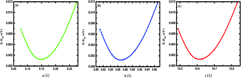 |
| | Fig. 1 Difference in energy (E–E0) in eV as a function of the lattice constants of Na2SiO3 (a) a (Å), (b) b (Å) and (c) c (Å). E0 indicates the minimum ground state energy. | |
Table 1 Calculated optimised lattice parameters of Na2SiO3 compared to B3LYP (Belmonte et al.47), PBE (Cuautli et al.46) and experimental (McDonald et al.48) results [swapped x and z axis (a ↔ c)]
| Parameters |
PBE–GGA (this work) |
B3LYP47 |
PBE46 |
Exp.48 |
| a (Å) |
6.158 |
6.0977 |
6.16 |
6.07 |
| b (Å) |
4.876 |
4.8523 |
4.88 |
4.82 |
| c (Å) |
10.630 |
10.5676 |
10.63 |
10.48 |
| V (Å3) |
319.20 |
312.673 |
319.546 |
306.6 |
The change in lattice parameters under unidirectional compressive pressure in the pressure range 0 → 50 GPa are reported in Table 2. The current work gives a thorough study of the structural deformation under the unidirectional compressive pressure (0–50 GPa). However, we do not have sufficient experimental or theoretical data to compare the results of pressure related studies for Na2SiO3. With the increase in pressure, the negative deformation along the lattice constant ‘Δc’ and the positive one along ‘Δa’ and ‘Δb’, indicates compression and tensile strain, respectively (see Table 2). On application of compressive pressure the change in lattice parameter ‘c’ is high as compared to ‘a’ and ‘b’ due to the unconstrained x and y-axes as a result of the dissipation of tensile stress along the x- and y-axes. This specifies that our compressive pressure is unidirectional acting along the lattice parameter ‘c’. The structural deformations at different pressures led to a change in the optimised unit cell volume as: at P = 0, 10, 20, 30, 40, 50 (in GPa), V = 319.2, 328.5, 319.4, 311, 305.1, 301.6 (in Å3), respectively.
Table 2 Calculated lattice parameters in Å and the change in lattice parameters with respect to the pristine cell in Å under different unidirectional pressure in GPa [swapped x and z axis (a ↔ c)]
| P |
a |
b |
c |
Δa |
Δb |
Δc |
| 0 |
6.158 |
4.876 |
10.630 |
0 |
0 |
0 |
| 10 |
6.157 |
5.221 |
10.22 |
−0.001 |
0.345 |
−0.41 |
| 12 |
6.198 |
5.233 |
10.08 |
0.040 |
0.357 |
−0.55 |
| 20 |
6.326 |
5.276 |
9.569 |
0.168 |
0.400 |
−1.061 |
| 30 |
6.446 |
5.316 |
9.077 |
0.288 |
0.440 |
−1.553 |
| 40 |
6.531 |
5.348 |
8.736 |
0.373 |
0.472 |
−1.894 |
| 50 |
6.588 |
5.388 |
8.497 |
0.430 |
0.512 |
−2.133 |
The hallmarks of the Na2SiO3 structure are the presence of [SiO4] tetrahedral chains and the existence of BO and the NBO bonds where the sodium atoms are attached. The presence of NBOs in the structure make a large distortion on the tetrahedral [SiO4] units.18 Initially, at 0 GPa pressure, our Na2SiO3 exists as an orthorhombic crystal structure with space group Cmc21. As shown in Fig. 2, Na2SiO3 experiences a structural phase transition from the orthorhombic Cmc21 space group to the lower primitive symmetry of a triclinic crystal structure with space group P1 at 12 GPa.
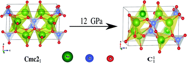 |
| | Fig. 2 Phase transition from Cmc21 → C11 under 12 GPa unidirectional compressive pressure. | |
3.2 Mechanical properties
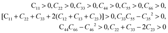
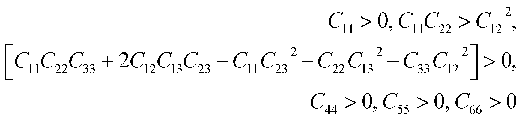
This section is about the mechanical properties of Na2SiO3. In order to perceive whether our compound meets the required stability and durability for practical applications, knowledge of its mechanical and elastic properties are essential. We have calculated the elastic constants and other mechanical properties for Na2SiO3 under different compressive unidirectional pressure. Our calculated elastic constants (as shown in Table 3) and the elastic constants calculated by Belmonte et al.47 (using LCAO DFT/B3LYP functionals) are different due to the difference in the exchange-correlation functionals employed. However, the two results satisfy the necessary and sufficient Born criteria of mechanical stability for an orthorhombic system:49| |
 | (1) |
Table 3 Calculated elastic constants Cij under different unidirectional pressure (both in GPa units). Here, at 0 and 10 GPa Na2SiO3 is in the orthorhombic (Cmc21) phase and between 12–50 GPa Na2SiO3 is in the triclinic (P1) phase
| P |
C11 |
C22 |
C33 |
C44 |
C55 |
C66 |
C12 |
C13 |
C23 |
C35 |
C46 |
C15 |
C25 |
| 0 |
57.36 |
43.76 |
59.70 |
24.32 |
51.91 |
27.74 |
43.47 |
19.38 |
10.51 |
— |
— |
— |
— |
| 10 |
52.60 |
157.37 |
111.47 |
38.05 |
21.60 |
50.56 |
29.81 |
34.62 |
42.08 |
— |
— |
— |
— |
| 12 |
45.27 |
154.18 |
135.71 |
36.35 |
26.58 |
48.35 |
34.21 |
43.54 |
53.20 |
−11.11 |
−9.94 |
−5.28 |
−6.08 |
| 20 |
80.36 |
179.37 |
188.73 |
27.41 |
18.38 |
55.80 |
53.81 |
45.66 |
60.86 |
−2.28 |
−2.62 |
−8.08 |
−4.58 |
| 30 |
118.92 |
189.26 |
196.31 |
20.92 |
16.46 |
59.71 |
71.84 |
58.66 |
62.90 |
1.24 |
−1.68 |
−2.48 |
−0.31 |
| 40 |
131.05 |
180.53 |
207.47 |
17.47 |
16.62 |
62.87 |
71.60 |
66.00 |
68.26 |
0.36 |
−0.82 |
−2.66 |
−1.47 |
| 50 |
5.25 |
180.28 |
169.59 |
22.00 |
30.47 |
53.31 |
19.14 |
41.27 |
57.20 |
5.05 |
5.32 |
−28.00 |
−13.01 |
From Table 3, it can be seen that the stability criteria for the orthorhombic system are satisfied at 0 and 10 GPa pressure showing the mechanical stability of the orthorhombic phase of Na2SiO3. In the previous sub-section, we have reported that there is a phase transition from orthorhombic Cmc21 to triclinic P1 at 12 GPa pressure. Further, for the triclinic system the Born criteria of mechanical stability are:49,50
| |
 | (2) |
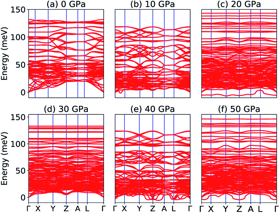
Our calculated elastic constants in the pressure range 12–50 GPa (as shown in Table 3) satisfy the above-mentioned mechanical stability criteria for the triclinic phase of Na2SiO3. The agreement of the stability criteria show that our system for Na2SiO3 is mechanically stable at the different compressive pressure ranges, 0–50 GPa. This is also confirmed by the fact that the stiffness matrix is positive at all pressures except at P = 50 GPa as can be seen in the eigenvalues reported in Table 5. At 50 GPa there is a mismatch between the Born criteria for mechanical stability and the stiffness matrix eigenvalues where we get a negative value at λ1. Mouhat et al.49 reported that when studying low-symmetry crystals like monoclinic and triclinic, it was usually more convenient to keep the stiffness coefficients in the matrix form and check whether all eigenvalues of C were positive. In Fig. 3, we present the calculated phonon dispersion curves of Na2SiO3 to test its dynamical stability between 0–50 GPa. Since, the unit cell consists of 24 atoms, there are 72 branches in the phonon dispersion curve. At 0 and 30 GPa [see Fig. 3(a and d)] we observe positive phonon spectra, this implies that Na2SiO3 is dynamically stable at these pressures. However, at 10, 20, 40 and 50 GPa [see Fig. 3(b, c, e and f)] we obtain small negative phonon spectra which could just be numerical noise in the calculation, as the lowest phonon curve does not cross the energy value of −10 meV in any of the four cases. This implies that the considered system i.e., Na2SiO3 is dynamically stable between the applied mechanical stress of 0–50 GPa. From Table 3, it is obvious that between P = 10–40 GPa our calculated C11, C22, C33 are considerably larger than C66, C55, C44 which shows that Na2SiO3 has more resistance to axial compression as compared to shear deformation. This can be confirmed by comparing the bulk modulus and shear modulus reported in Table 4. From the analysis of our calculated elastic constants (Cij), it can be seen that C11 and C22 decreases while C55 increases when pressure escalates from 10 GPa to 12 GPa, this suggests that there is a tendency of phase transition from orthorhombic Cmc21 to the lower symmetry phase (see Fig. 2).
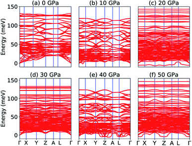 |
| | Fig. 3 Phonon dispersion curve of Na2SiO3 under (a) 0 GPa, (b) 10 GPa, (c) 20 GPa, (d) 30 GPa, (e) 40 GPa, (f) 50 GPa. | |
Table 4 Calculated elastic moduli (bulk modulus (B), Young’s modulus (Y), and shear modulus (G) all in GPa) and Poisson’s ratio (ν) (unitless) under varying unidirectional pressure (in GPa units). Here, the subscripts V, R and H represent Voigt, Reuss and Hill assumptions, respectively
| P |
BV |
BR |
BH |
YV |
YR |
YH |
GV |
GR |
GH |
νV |
νR |
νH |
| 0 |
34.171 |
26.067 |
30.119 |
63.406 |
27.146 |
45.921 |
26.625 |
10.233 |
18.429 |
0.19074 |
0.32643 |
0.24589 |
| 10 |
59.384 |
41.197 |
50.291 |
90.613 |
67.677 |
79.168 |
36.371 |
27.596 |
31.983 |
0.24569 |
0.22621 |
0.23763 |
| 12 |
66.34 |
42.744 |
54.542 |
91.177 |
67.057 |
79.182 |
35.87 |
27.071 |
31.471 |
0.27094 |
0.23853 |
0.25804 |
| 20 |
85.458 |
68.677 |
77.068 |
102.74 |
79.334 |
91.042 |
39.527 |
30.339 |
34.933 |
0.29963 |
0.30747 |
0.30311 |
| 30 |
99.032 |
93.485 |
96.259 |
106.13 |
79.365 |
92.894 |
40.157 |
29.21 |
34.684 |
0.32139 |
0.35851 |
0.33916 |
| 40 |
103.42 |
99.311 |
101.37 |
106.93 |
77.512 |
92.424 |
40.271 |
28.291 |
34.281 |
0.32767 |
0.36992 |
0.34803 |
| 50 |
65.593 |
−118.29 |
−26.349 |
93.411 |
601.82 |
−5549.5 |
36.99 |
128.16 |
82.574 |
0.26265 |
1.34790 |
−34.603 |
Table 5 Calculated eigenvalues of stiffness matrix (in GPa units) calculated from elastic constants under different unidirectional pressures
| P |
λ1 |
λ2 |
λ3 |
λ4 |
λ5 |
λ6 |
| 0 |
5.7103 |
19.843 |
28.63 |
47.31 |
50.672 |
112.62 |
| 10 |
16.694 |
32.253 |
41.275 |
54.111 |
90.336 |
196.98 |
| 12 |
23.039 |
25.862 |
32.821 |
54.016 |
93.228 |
217.47 |
| 20 |
16.984 |
27.313 |
54.458 |
56.227 |
123.93 |
271.14 |
| 30 |
15.739 |
20.84 |
60.16 |
70.957 |
131.56 |
302.32 |
| 40 |
15.909 |
17.629 |
63.062 |
77.369 |
127.3 |
314.75 |
| 50 |
−20.633 |
21.085 |
44.627 |
54.416 |
120.81 |
240.59 |
In Table 4, the calculated elastic moduli and the Poisson’s ratio under different compressive pressures are reported. Our reported bulk modulus (B), Young’s modulus (Y) and shear modulus (G) are estimated in Voigt (uniform strain assumption),51 Reuss (uniform stress assumption)52 and Hill assumption.53 It can be seen that there are regular or small fluctuations in our calculated elastic moduli from 0–40 GPa pressures indicating that our system is mechanically stable. At P = 50 GPa, the elastic moduli fluctuate very high or our calculated elastic moduli are out of order compared to lower pressures (i.e. 0–40 GPa), which might be due to the fact that our system (Na2SiO3) shows mechanical instability at 50 GPa. Glass-like Na2SiO3 materials are usually brittle.54 The brittleness or ductility is generally characterized by the values of Poisson’s ratio. We have reported our calculated Poisson’s ratio (ν) estimated using the Voigt, Reuss and Hill assumptions. From Table 4, it is obvious that the value of ν increases with pressure showing that Na2SiO3 becomes more ductile with pressure. Interestingly, between 0–40 GPa, one can find that our system undergoes tensile deformation which can be confirmed by the fact that all the Poisson’s ratios are positive in this range of pressure. However, at 50 GPa, the value of νH falls drastically to become negative. This negative Poisson’s ratio (at νH = −34.603, see Table 4) results in compressive deformation. Thus, at 50 GPa, Na2SiO3 shows auxetic material properties which have wide applications possibilities in biomedical field, surgical implants and even for piezoelectric sensors and actuators.55–58
3.3 Electronic properties
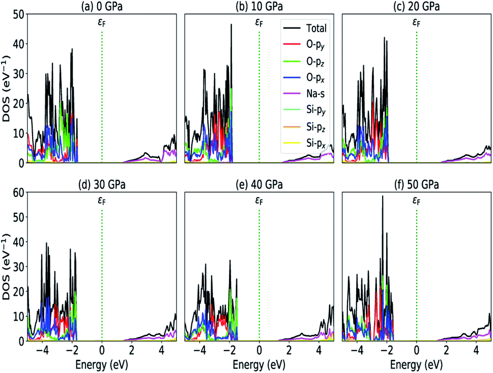
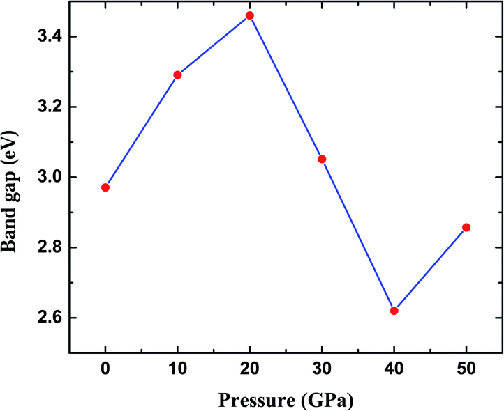
The most fundamental property while investigating atomic level interactions in any material is the electronic property. In this section, we present detailed results of the electronic properties of pristine Na2SiO3 (0 Gpa) and Na2SiO3 at five different pressures. Fig. 4 and 5 show the calculated electronic band structures and partial density of states (PDOS) for Na2SiO3, respectively. It is found that the top of the valence bands (VBs) have small dispersions while the bottom of the conduction bands (CBs) have large dispersions for all different compressive pressures (see Fig. 4). This is in good agreement with the electronic band structure result reported by Lui et al.59 using ab initio total-energy and force calculations within the local density approximation (LDA) via a preconditioned conjugate gradient algorithm. From our calculation, at P = 0 GPa [see Fig. 4(a)], the highest energy of the valence band is at the Z point, and the lowest energy of the conduction band is at the Γ point, and with an indirect (Z to Γ points) band gap of 2.97 eV. Experimentally, Sigel60 reported a band gap of 6 eV for silicate glasses. It is well known that PBE–GGA density functional theory calculations usually underestimate the band gap. An indirect (Z to Γ points) band gap was reported by Lui et al.59 but with a band gap value of 4 eV. Ching et al.18 reported band gap values of 6.46 eV with  and 9.98 eV with α = 1.0 and concluded that the band gap of Na2SiO3 is very dependent on the exchange parameter used. In this work, we have done electronic band structure calculations under compressive pressures in the pressure range 0–50 GPa with a difference of 10 GPa. It is found that the highest energy point of the valence band changes with pressure while the bottom of the conduction band is at Γ point at each pressure, see Fig. 4(a–f). It is obvious that the application of pressure changes the lattice parameters and so the average distance between electron or hole. This in turn changes the magnitude of the electron–hole ion potential. This change in the potential is significant as it plays an important role in determining the band gap at the Brillouin zone. In this work, we have found that the band gap fluctuates with the application of pressure. Initially, the band gap increases up to 20 GPa, and from 20–40 GPa the band gap decreases linearly. From 40–50 GPa, the band gap starts to increase again (see Fig. 6 for variation of band gap with the application of pressure). Obviously, the band gap should decrease with increasing applied pressure but, from our calculation, we can clarify that the variation in band gap with the application of pressure does not follow a specific trend (i.e., there is a rise and fall in the band gap value when the amount of applied pressure increases). This might be due to the nature of the material being investigating.
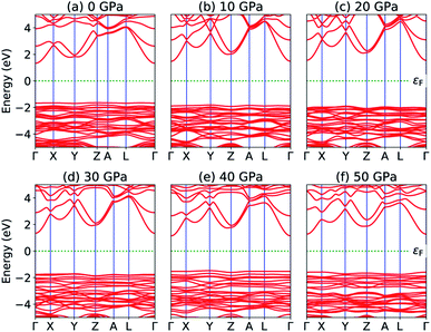 |
| | Fig. 4 Calculated band structure (a) P = 0 GPa, (b) P = 10 GPa, (c) P = 20 GPa, (d) P = 30 GPa, (e) P = 40 GPa and (e) P = 50 GPa. | |
 |
| | Fig. 5 Partial density of states (a) P = 0 GPa, (b) P = 10 GPa, (c) P = 20 GPa, (d) P = 30 GPa, (e) P = 40 GPa and (e) P = 50 GPa. | |
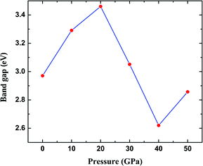 |
| | Fig. 6 Calculated band gap (in eV) versus pressure (in GPa) for Na2SiO3. Here, the red dots represent the corresponding band gaps at 0, 10, 20, 30, 40, 50 GPa. | |
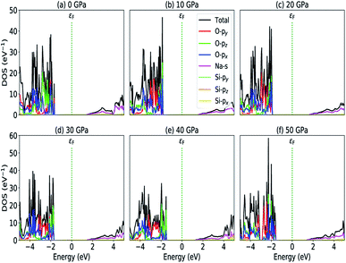
The calculated PDOS of Na2SiO3 at 0 GPa, 10 GPa, 20 GPa, 30 GPa, 40 GPa and 50 GPa are shown in Fig. 5 (a)–(f), respectively. The Fermi level (εF) is set at 0 eV which lies between the valence band and the conduction band. At 0 GPa, the energy states around the top of the valence band are mainly contributed by the states O-2px and O-2py orbitals. And, the valence band electronic states are mainly distributed in the energy range from −3.8 eV to −1.8 eV owing to the hybridization of O-2px, O-2py, O-2pz and Si-3px. The energy states around the bottom of the conduction band are composed mainly of the Na-3s orbitals and also, we could find a slight contribution from Si-3px orbitals. With the application of pressure, the main contributors of the energy state at the top of the valence band changes i.e., from the state O-2py to O-2pz until it reaches 40 GPa [see Fig. 5(b, c, d and e)] while, the energy states which contributed the bottom of the conduction band remains consistent. Clearly, we could find an overall shift of both the valence band and conduction band when pressure increases. At 10 and 20 GPa both the top of the valence band and the bottom of the conduction band shift away from the Fermi level (εF). Therefore, the band gap is large, and hence, light of a higher frequency and lower wavelength would be absorbed. Between 30–50 GPa, we observed the reverse characteristic where both the top of the valence band and the bottom of the conduction band shift towards the Fermi level (εF). As a result, there is a reduction in band gap and therefore light absorption in the visible range might be improved.
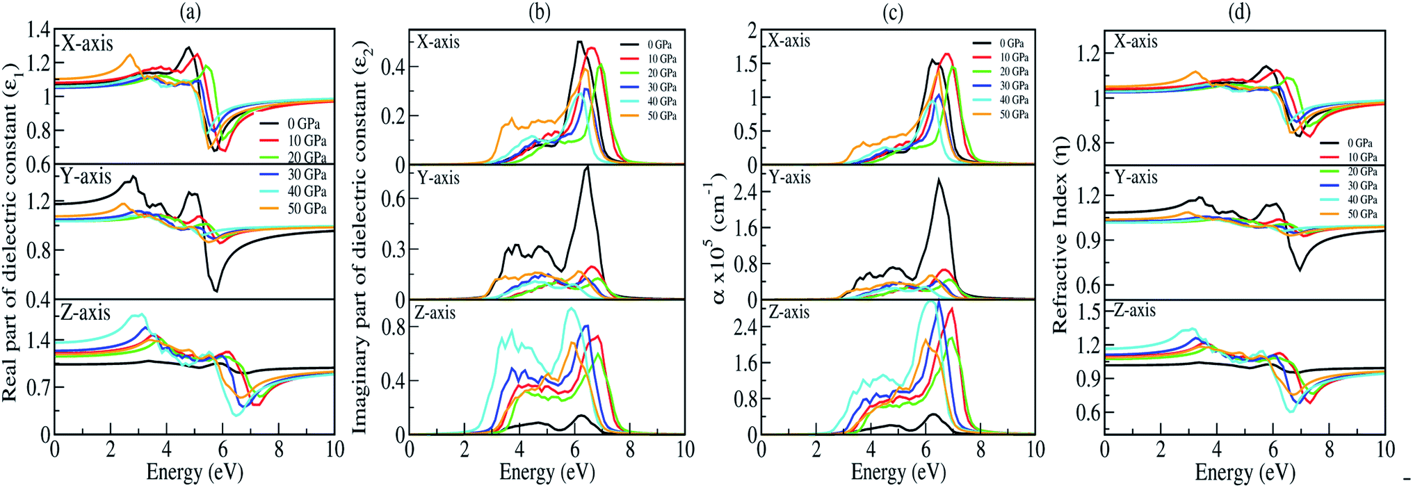
3.4 Optical properties
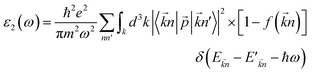
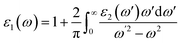
The optical properties of a material define how the material interacts with electromagnetic radiation.61 So, a detailed study of the optical properties is crucial in many industrial and scientific applications such as heat transfer, contactless temperature measurement, laser technology, optics industry for the productions of mirrors, lenses and optical windows, photovoltaic industry, the aerospace industry and so on.62,63 Therefore, we have studied the optical properties of Na2SiO3 at different compressive pressures by calculating the dielectric constant (ε), absorption coefficient (α) and refractive index (η) as a function of the photon energy (eV). We have calculated the optical properties of Na2SiO3 in terms of complex dielectric function which is closely related to the interaction between the photons (electromagnetic radiation) and the electrons (atoms), therefore it is represented by both the real and the imaginary parts given by:64–67where ε1 and ε2 are the real part and imaginary part of the dielectric constant, respectively. The above equation is mainly connected with the electronic structures and determines the linear response of the material to electromagnetic radiation. The imaginary part (ε2) is related to the electronic band and represents the optical absorption in the crystal and is given by:64–67| |
 | (4) |
where ![[p with combining right harpoon above (vector)]](https://www.rsc.org/images/entities/i_char_0070_20d1.gif) is the momentum operator, |
is the momentum operator, |![[k with combining right harpoon above (vector)]](https://www.rsc.org/images/entities/i_char_006b_20d1.gif) n〉 is the eigenfunction of the eigenvalue En and f(n) is the Fermi distribution function. The real part (ε1) is evaluated from the imaginary part (ε2) using the Kramers–Kronig transformation68 which is given by:
n〉 is the eigenfunction of the eigenvalue En and f(n) is the Fermi distribution function. The real part (ε1) is evaluated from the imaginary part (ε2) using the Kramers–Kronig transformation68 which is given by:| |
 | (5) |
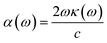
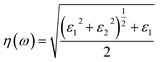
The optical constant, the refractive index (η) can be computed from the complex dielectric function (ε1). The absorption coefficient (α) and the refractive index (η) which are the optical properties related to the dielectric function and are given by:| |
 | (6) |
where κ(ω) is the extinction coefficient related to the imaginary part of the complex refractive index.| |
 | (7) |
The presence of discrete spikes in the electronic density of states influences the optical properties. The real part (ε1) and imaginary part (ε2) of the dielectric constant as a function of the photon energy up to 10 eV along the x, y, z-axes under P = 0, 10, 20, 30, 40, 50 GPa’s are presented in Fig. 7(a and b). The calculated static real dielectric function ε1(0) (at E = 0.0 eV) along the x, y, z-axes are presented in Table 6. The real dielectric function ε1 shows anisotropic behaviour up to 10 eV, beyond 10 eV the values of ε1 are ∼1 arb. unit under different applied pressures along different axes exhibiting negligible effects of pressure on the ε1 for high values of photon energy. Meanwhile, along the x-axis one could find one prominent peak for each different pressure, as shown in Fig. 7(a) (top). For 0 GPa the peak point is at around 5.0 eV with a value of 1.3 arb. unit. The peak points shifted to the higher energy region as pressure increases until it reaches 20 GPa, and from 30 GPa the peak points shift back to the lower energy region until the pressure reaches 50 GPa where the peak point is at around 2.85 eV with a peak value of 1.24 arb. unit. The value of ε1x goes to a lower value after reaching the maximum point. The minimum points for all different pressures are in the energy region where the photon energy is at 5–6.2 eV with the minimum value in the range of 0.65–0.80 arb. unit. However, along the y-axis, as shown in Fig. 7(a) (middle), we note two prominent peak points for 0 GPa where the first peak is at around 2.85 eV and the second peak is at around 4.8 eV with peak values of ∼1.4 and ∼1.3 arb. unit, respectively, and as the photon energy is increasing ε1y drops below 0.5 arb. unit at around 6 eV. The peak value as well as the lowest value of ε1y at 0 GPa are comparatively high and low, respectively, when comparing with the peak value and the lowest value at all other pressures being applied within the same energy range. This indicates that along the y-axis, the photon energy might have the greatest effect on the refractive index when the pressure is at 0 GPa. Considering the second peak, one can note that ε1y shows similar behaviour as that in the case of ε1x where the peak points shift to the higher photon energy region and go back to the lower photon energy when pressure is increased. Along the z-axis, as shown in Fig. 7(a) (bottom), the value of ε1z at 0 GPa almost remains the same throughout the energy range, it has a maximum peak value at around 6 eV with a value of ∼1.05 arb. unit. As pressure increases the peak points are shifted to the lower energy region within the energy range 3.0–4.0 eV. At 40 GPa one could find the highest peak for this axis which is at around 3.0 eV with a value of ∼1.75 arb. unit.
 |
| | Fig. 7 Optical parameters as a function of the photon energy (in eV) under 0, 10, 20, 30, 40, and 50 GPa pressures: (a) real part of the dielectric function (ε1), (b) imaginary part of the dielectric function (ε2), (c) absorption coefficient (α) and (d) refractive index (η). | |
Table 6 Calculated static real part of the dielectric constant ε1(0) and static refractive indices η(0) along the x, y, z-axes under 0, 10, 20, 30, 40 and 50 GPa pressures
| P |
ε1x(0) |
ε1y(0) |
ε1z(0) |
ηx(0) |
ηy(0) |
ηz(0) |
| 0 |
1.07 |
1.18 |
1.04 |
1.03 |
1.08 |
1.01 |
| 10 |
1.08 |
1.04 |
1.20 |
1.04 |
1.02 |
1.09 |
| 20 |
1.05 |
1.03 |
1.16 |
1.02 |
1.01 |
1.07 |
| 30 |
1.05 |
1.05 |
1.24 |
1.02 |
1.02 |
1.10 |
| 40 |
1.06 |
1.03 |
1.36 |
1.02 |
1.01 |
1.16 |
| 50 |
1.11 |
1.08 |
1.18 |
1.05 |
1.03 |
1.08 |
The imaginary part of the dielectric constant ε2 is interconnected with the dielectric loss, and also corresponds to the inter-band transition between the valence band and conduction band. It is highly correlated with the optical absorption (α) of a material [see Fig. 7(c)]. Plot of the imaginary part of the dielectric constant (ε2) as a function of the photon is shown in Fig. 7(b). Along the x and y-axes, one can note that the peak points of ε2x and ε2y [see Fig. 7(b) (top and middle)] are shifted to the higher photon energy region when pressure increases, until the pressure reaches 20 GPa but above this the peak points shift back towards the lower energy region which is very similar to the one we obtained in the real part. However, when analyzing our calculated data for ε2 along the z-axis, it clearly shows that within the same energy range the ε2z has a much higher value when comparing with ε2x and ε2y, except at 0 GPa. This is due to the fact that the pressure is applied along the z-axis. We have measured absorption coefficients (α) along the x, y, z-axes as a function of incident photon energy as shown in Fig. 7(c). Here, we can see very strong optical absorption along the x, y, z-axes (αx, αy, αz) under different pressures within the energy range 0–10 eV. The most active region is found between 2.5 eV to 8.0 eV. The absorption spectra is highly anisotropic in nature. Our main concern is to observe the variation of absorption spectra under the applied pressure for its potential application in optoelectronic devices. Our results of absorption spectra are very interesting because they fall within the UV-Vis range. Referring to Fig. 7(c) (bottom), the absorption spectra peaks show a blue shift up to 20 GPa pressure, after which there is a small red shift as compared to the one at 0 GPa. The intensity of absorption spectra increases as we keep increasing the pressure up to 40 GPa. The minimum threshold energy is found to be 2.5 eV which corresponds to an optical band gap in good agreement with the electronic band gap at 40 GPa [Fig. 7(c) (bottom)]. We have observed four prominent peaks at 3.2 eV, 3.8 eV, 4.5 eV and 6 eV. The optical band gap is a result of the first direct electron transition from the top of the valence band (O-pz) to the bottom of the conduction band (Na-s) along Γ-symmetry. The first peak at 3.2 eV is a result of the transition from the third band of the valence region to the bottom of the conduction band (Γ-symmetry). The second peak at 3.8 eV is a probability transition from the top of the valence band to the bottom of the conduction band along the z-symmetry point. The third peak at 4.5 eV is due to the outcome of the transition from the second band of the valence region to the first band of the conduction region along the x-symmetry point. The last peak at 6 eV having maximum intensity, is due to a transition from the third band of the valence region to the third band of the conduction region along the x-symmetry point. Interestingly, the maximum intensity peaks shift towards higher energy with increasing pressure for the x- and y-axes which is contrary to the absorption spectra peak measured along the z-axis. This discrepancy is due to the tensile strain along the x- and y-axes while the compressive strain is experienced by the atom along the z-axis on application of unidirectional pressure (along the z-axis).
The calculated spectra of refractive indices (η) along the x, y, z-axes are presented in Fig. 7(d). The static refractive indices ηx,y,z(0) are given in Table 6. Clearly, all the values are close to unity at 0 eV indicating that our system Na2Si03, is transparent in nature. Recently, Baral et al.69 reported the high refractive index of (Na2O)x (SiO2)1−x when sodium oxide concentration is increased. Using the orthogonal linear combination of atomic orbitals (OLCAO) method in the VASP-relaxed structures he reported an η value in the range of 1.415–1.530 when the concentration was x = 0–0.5. On analysing the variation of refractive indices (η) with respect to the incident photon energy (eV) under unidirectional pressure along the z-axis, one can find the change in refractive index is almost negligible along the x- and y-axes up to around 5.5 eV even when the pressure reaches 50 GPa [see Fig. 7(d) (top and middle)]. However, referring to Fig. 7(d) (bottom), along the z-axis we note isotropic behaviour. The refractive indices start increasing at around 3 eV as pressure escalates compared to at 0 GPa where the value almost remains at unity throughout the whole incident photon energy. Meanwhile, above 6 eV the values of all the refractive indices (i.e., along x, y, z) falls below 1 up to around 10 eV [see Fig. 7(d)]. This seems physically impossible as a refractive index of below 1 occurs only when the speed of light is exceeded by phase velocity of an electromagnetic wave (νp > c). In addition, this phenomenon arises due to the presence of plasmonic vibration.
3.5 Piezoelectric properties
It is well-known that the piezoelectric properties of a material arises as a result of the atomic scale polarization which could be due to the application of mechanical stress.70 The study of piezoelectric properties of a material has become an interesting topic among researchers as those materials have industrial applications – as actuators, sensors, microphones and so on – also they have applications in medical devices for monitoring heartbeats and breathing.71–78 To our knowledge this insight study of piezoelectric properties of a material are usually based on the study of piezoelectric tensors (dkij).79,80 Interestingly, in this section we are going to discuss the piezoelectric properties of glass-like Na2SiO3 by calculating the total Cartesian polarization under different compressive unidirectional pressure as shown in Table 7. Our calculations are simply based on modern theory of polarization where the spontaneous polarization of a material is calculated to understand its ferroelectric properties. Since quartz (SiO2) is a naturally occurring single crystalline piezoelectric material, our system of Na2SiO3 has the possibility of showing piezoelectric properties. In modern theory of polarization, polarization of a material is divided into two parts; electronic and ionic. The contribution of the electronic part to polarization is given as:81| |
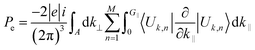 | (8) |
Here, the summation runs over occupied bands, and k‖ is parallel to the direction of polarization, and G‖ is a reciprocal lattice vector in the same direction. The states |Uk,n〉 are the cell-periodic parts of the Bloch functions, ψk,n = Un,k(r)![[thin space (1/6-em)]](https://www.rsc.org/images/entities/char_2009.gif) eik.r.
eik.r.
Table 7 Calculated total Cartesian polarization Pt(c) in cm−2 along the x, y, z-axes under different compressive unidirectional pressures
| P |
0 |
10 |
20 |
30 |
40 |
50 |
| x |
−2.97064990 × 10⁻³ |
−2.66488487 × 10⁻² |
2.36226850 × 10⁻² |
−7.18990850 × 10⁻³ |
−9.0549006 × 10⁻³ |
1.77675552 × 10⁻² |
| y |
−2.29594955 × 10⁻² |
4.11457135 × 10⁻² |
6.31891403 × 10⁻² |
7.57134265 × 10⁻² |
6.49859613 × 10⁻² |
−6.33370486 × 10⁻² |
| z |
1.00901047 × 10⁻¹ |
1.64564653 × 10⁻² |
8.47809484 × 10⁻³ |
−5.85834073 × 10⁻³ |
−3.35035488 × 10⁻³ |
1.39032451 × 10⁻³ |
The electronic polarization part is simply calculated by the classical electrostatic sum of point charges given as:
| |
 | (9) |
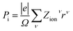
where the summation runs over all the ions in the unit cell, and
Zionν and
rν are the valence charge and position vector of atom
ν, and
Ω is the unit cell.
The total Cartesian polarization (Pt(c)) is calculated by taking the product of total fractional polarization (Pt) and polarization quantum (Pq), i.e.,
where
Pt =
Pe +
Pi is the sum of electronic and ionic polarization parts and

is the polarization quantum, here, |
e| is the electronic charge,
Rj is the lattice vector,
j and
Ω the unit cell volume.
Our calculated total Cartesian polarization in cm−2 under different compressive unidirectional pressures are given in Table 7. From our calculations, one can see that at 0 GPa the Cartesian polarization is maximum along the z-direction with a value of ∼ 0.1 cm−2. This indicates that Na2SiO3 shows some ferroelectric properties. However, when pressure is applied along the z-axis, it is obvious that one will notice compressive stress along the z-axis with tensile stress observed along both the x- and y-axes. This structural change with pressure will patently distort the negative cloud of electrons around the positive atomic nuclei. This slight separation will result in an electric field between them, and consequently polarization is created which can be manipulated to give novel piezoelectric properties. Our biggest concern is to obtain the Cartesian polarization of Na2SiO3 for its potential application in piezoelectric materials. Interestingly, from Table 7 we have observed that the maximum polarization axis changes from z to y-axes as pressure increases from 0 GPa to 40 GPa. At 50 GPa the Cartesian polarization has its highest value along the x-axis. The calculated Cartesian polarization for 10, 20, 30, 40 and 50 GPa are ∼ 0.041, 0.063, 0.076, 0.065 and 0.018 (in cm−2) which are fairly low. Therefore, to use Na2SiO3 in practical ferroelectric and piezoelectric devices, rigorous research is necessary which could further enhance its polarizability.
4 Conclusions
In summary, we have studied the properties of Na2SiO3 using DFT calculations under varying unidirectional compressive pressure. Our findings reveal that Na2SiO3 is a stable structure which shows mechanical stability up to 40 GPa. And at 12 GPa, our system experiences a structural phase transition from orthorhombic Cmc21 to a lower primitive symmetry triclinic P1 structure. Also, at 50 GPa Na2SiO3 is found to be an auxetic material which opens up its potential application in the field of biomedical and other electronic devices. Interestingly, Na2SiO3 is also found to have its optical absorbance within the UV-Vis range. The value of ηx,y,z(0) ∼1 has revealed that Na2SiO3 is transparent in nature. Therefore, it is a promising material for optoelectronic devices.
Conflicts of interest
There are no conflicts to declare.
Acknowledgements
D. P. Rai acknowledges the Government of India, Ministry of Science and Technology, Department of Science & Technology (International Bilateral Cooperation Division) for supporting the Indo-Uzbek joint project via Sanction No. INT/UZBEK/P-02. M.P.G. acknowledges the Alexander von Humboldt Foundation, Germany, for the equipment grants; and IFW-Dresden, Germany, for providing the large-scale computing hardware to Tribhuvan University for the scientific computations.
References
- L.-g. Liu, Geophys. Res. Lett., 1987, 14, 1079–1082 CrossRef CAS.
- J. M. D. Coey, Mössbauer Spectroscopy Applied to Inorganic Chemistry, Springer US, Boston, MA, 1984, pp. 443–509 Search PubMed.
- L. Zhu, Y. R. Zeng, J. Wen, L. Li and T. M. Cheng, Electrochim. Acta, 2018, 292, 190–198 CrossRef CAS.
- Y. Ren, Y. Zhang, Y. Gu and Q. Zeng, Prog. Org. Coat., 2017, 112, 225–233 CrossRef CAS.
- M. Lancry, E. Régnier and B. Poumellec, Prog. Mater. Sci., 2012, 57, 63–94 CrossRef CAS.
- S. Kaya, M. Cresswell and A. R. Boccaccini, Mater. Sci. Eng. C, 2018, 83, 99–107 CrossRef CAS PubMed.
- E. Borsella, E. Cattaruzza, G. De Marchi, F. Gonella, G. Mattei, P. Mazzoldi, A. Quaranta, G. Battaglin and R. Polloni, J. Non-Cryst. Solids, 1999, 245, 122–128 CrossRef CAS.
- J. O. Bockris, J. D. Mackenzie and J. A. Kitchener, Trans. Faraday Soc., 1955, 51, 1734 RSC.
- C. A. Faick and A. N. Finn, J. Am. Ceram. Soc., 1931, 14, 518–528 CrossRef CAS.
- L. Shartsis, S. Spinner and W. Capps, J. Am. Ceram. Soc., 1952, 35, 155–160 CrossRef CAS.
- T. Uchino, M. Iwasaki, T. Sakka and Y. Ogata, J. Phys. Chem., 1991, 95, 5455–5462 CrossRef CAS.
- A. K. Varshneya and J. C. Mauro, Fundam. Inorg. Glas., 2019, 1–18 Search PubMed.
- J. T. Randall, H. P. Rooksby and B. S. Cooper, Z. Kristallogr. Cryst. Mater., 1930, 75, 196–214 CrossRef.
- W. H. Zachariasen, J. Am. Chem. Soc., 1932, 54, 3841–3851 CrossRef CAS.
- I. Farnan, Nature, 1997, 390, 14–15 CrossRef CAS.
- K. Baral, A. Li and W.-Y. Ching, J. Phys. Chem. A, 2017, 121, 7697–7708 CrossRef CAS PubMed.
- S. Kikuchi, N. Koga, H. Seino and S. Ohno, J. Nucl. Sci. Technol., 2016, 53, 682–691 CrossRef CAS.
- W. Y. Ching, R. A. Murray, D. J. Lam and B. W. Veal, Phys. Rev. B, 1983, 28, 4724–4735 CrossRef CAS.
- A. Grund and M. Pizy, Acta Crystallogr., 1952, 5, 837–840 CrossRef CAS.
- D. D. Le Pevelen, Encycl. Spectrosc. Spectrom., 2010, 2559–2576 Search PubMed.
- P. Richet, B. O. Mysen and D. Andrault, Phys. Chem. Miner., 1996, 23, 157–172 CrossRef CAS.
- G. Greaves, J. Non-Cryst. Solids, 1985, 71, 203–217 CrossRef CAS.
- Y. Cao, A. N. Cormack, A. G. Clare, B. Bachra, A. C. Wright, R. N. Sinclair and A. C. Hannon, J. Non-Cryst. Solids, 1994, 177, 317–323 CrossRef CAS.
- D. W. Matson, S. K. Sharma and J. A. Philpotts, J. Non-Cryst. Solids, 1983, 58, 323–352 CrossRef CAS.
- H. Maekawa, T. Maekawa, K. Kawamura and T. Yokokawa, J. Non-Cryst. Solids, 1991, 127, 53–64 CrossRef CAS.
- G. N. Greaves, S. J. Gurman, C. R. A. Catlow, A. V. Chadwick, S. Houde-Walter, C. M. B. Henderson and B. R. Dobson, Philos. Mag. A, 1991, 64, 1059–1072 CrossRef CAS.
- M. G. Mortuza, R. Dupree and D. Holland, J. Non-Cryst. Solids, 2001, 281, 108–116 CrossRef CAS.
- L. Olivier, X. Yuan, A. N. Cormack and C. Jäger, J. Non-Cryst. Solids, 2001, 53–66 CrossRef CAS.
- A. Meyer, J. Horbach, W. Kob, F. Kargl and H. Schober, Phys. Rev. Lett., 2004, 93, 027801 CrossRef CAS PubMed.
- B. Gee and H. Eckert, J. Phys. Chem., 1996, 100, 3705–3712 CrossRef CAS.
- G. N. Greaves, A. Fontaine, P. Lagarde, D. Raoux and S. J. Gurman, Nature, 1981, 293, 611–616 CrossRef CAS.
- Y. Kowada and D. E. Ellis, Adv. Quantum Chem., 1998, 29, 233–251 CrossRef.
- A. Bunde, M. Ingram, P. Maass and K. Ngai, J. Non-Cryst. Solids, 1991, 131–133, 1109–1112 CrossRef CAS.
- R. L. McGreevy and L. Pusztai, Mol. Simul., 1988, 1, 359–367 CrossRef.
- S. Ispas, M. Benoit, P. Jund and R. Jullien, Phys. Rev. B, 2001, 64, 214206 CrossRef.
- Z. Q. Hu, A. M. Wang and H. F. Zhang, Mod. Inorg. Synth. Chem., 2017, 641–667 CAS.
- S. Smidstrup, T. Markussen, P. Vancraeyveld, J. Wellendorff, J. Schneider, T. Gunst, B. Verstichel, D. Stradi, P. A. Khomyakov, U. G. Vej-Hansen, M.-E. Lee, S. T. Chill, F. Rasmussen, G. Penazzi, F. Corsetti, A. Ojanperä, K. Jensen, M. L. N. Palsgaard, U. Martinez, A. Blom, M. Brandbyge and K. Stokbro, J. Phys. Condens. Matter, 2020, 32, 015901 CrossRef CAS PubMed.
- S. Smidstrup, D. Stradi, J. Wellendorff, P. A. Khomyakov, U. G. Vej-Hansen, M.-E. Lee, T. Ghosh, E. Jónsson, H. Jónsson and K. Stokbro, Phys. Rev. B, 2017, 96, 195309 CrossRef.
- M. Schlipf and F. Gygi, Comput. Phys. Commun., 2015, 196, 36–44 CrossRef CAS.
- J. P. Perdew, K. Burke and M. Ernzerhof, Phys. Rev. Lett., 1996, 77, 3865–3868 CrossRef CAS PubMed.
- D. C. Liu and J. Nocedal, Math. Program., 1989, 45, 503–528 CrossRef.
- S. H. Hahn, J. Rimsza, L. Criscenti, W. Sun, L. Deng, J. Du, T. Liang, S. B. Sinnott and A. C. T. van Duin, J. Phys. Chem. C, 2018, 122, 19613–19624 CrossRef CAS.
- A. Pedone, G. Malavasi, A. N. Cormack, U. Segre and M. C. Menziani, Chem. Mater., 2007, 19, 3144–3154 CrossRef CAS.
- M. van Setten, M. Giantomassi, E. Bousquet, M. Verstraete, D. Hamann, X. Gonze and G.-M. Rignanese, Comput. Phys. Commun., 2018, 226, 39–54 CrossRef CAS.
- H. J. Monkhorst and J. D. Pack, Phys. Rev. B, 1976, 13, 5188–5192 CrossRef.
- C. Cuautli, I. Romero-Ibarra, J. Vazquez-Arenas and M. Galvan, Fuel, 2021, 298, 120840 CrossRef CAS.
- D. Belmonte, C. Gatti, G. Ottonello, P. Richet and M. V. Zuccolini, J. Phys. Chem. A, 2016, 120, 8881–8895 CrossRef CAS PubMed.
- W. S. McDonald and D. W. J. Cruickshank, Acta Crystallogr., 1967, 22, 37–43 CrossRef CAS.
- F. Mouhat and F.-X. Coudert, Phys. Rev. B, 2014, 90, 224104 CrossRef.
- Q. Guo, K. C. Lau and R. Pandey, J. Phys. Chem. C, 2019, 123, 4674–4681 CrossRef CAS.
- W. Voigt, Lehrbuch der Kristallphysik. Teubner Verlag, Leipzig, 1928. References - Scientific Research Publishing Search PubMed.
- A. Reuss, Z. Angew. Math. Mech., 1929, 9, 49–58 CrossRef CAS.
- R. Hill, Proc. Phys. Soc. Sect. A, 1952, 65, 349–354 CrossRef.
- S. Chokka and K. Traipanya, Suranaree J. Sci. Technol., 2017, 24, 407–414 Search PubMed.
- M. Sanami, PhD thesis, Institute for Materials Research and Innovation, University of Bolton, Deane Road, Bolton BL3 5AB, UK, 2015.
- E. P. Hadjigeorgiou and G. E. Stavroulakis, Comput. Methods Sci. Technol., 2004, 10, 147–160 CrossRef.
- S. Farhangdoust, S. M. Aghaei, M. Amirahmadi, N. Pala and A. Mehrabi, Sensors Smart Struct. Technol. Civil, Mech. Aerosp. Syst., 2020, 2020, 36 Search PubMed.
- T. Fey, F. Eichhorn, G. Han, K. Ebert, M. Wegener, A. Roosen, K. I. Kakimoto and P. Greil, Smart Mater. Struct., 2015, 25, 015017 CrossRef.
- F. Liu, S. H. Garofalini, R. D. King-Smith and D. Vanderbilt, Chem. Phys. Lett., 1993, 215, 401–404 CrossRef CAS.
- G. H. SIGEL, TREATISE Mater. Sci. Technol., ACAdemic Press, INC., 1977, vol. 12, pp. 5–89 Search PubMed.
- V. Sudarsan, Funct. Mater., 2012, 285–322 CAS.
- L. Barnett, Dev. Agric. Eng., 1986, 8, 48–55 Search PubMed.
- A. K. Varshneya and J. C. Mauro, Dev. Agric. Eng., 1986, 8, 48–55 Search PubMed.
- C. Ambrosch-Draxl and J. O. Sofo, Comput. Phys. Commun., 2006, 175, 1–14 CrossRef CAS.
- D. P. Rai, T. V. Vu, A. Laref, M. P. Ghimire, P. K. Patra and S. Srivastava, Nano-Struct. Nano-Objects, 2020, 21, 100404 CrossRef CAS.
- B. Chettri, P. K. Patra, L. Lalhriatzuala, S. Verma, B. K. Rao, M. L. Verma, V. Thakur, N. Kumar, N. N. Hieu and D. P. Rai, Int. J. Quantum Chem., 2021, 121, e26680 CrossRef CAS.
- B. Chettri, P. K. Patra, T. V. Vu, C. Q. Nguyen, Lalrinkima, A. Yaya, K. O. Obodo, N. T. T. Tran, A. Laref and D. P. Rai, Phys. E, 2021, 126, 114436 CrossRef CAS.
- P. C. Martin, Phys. Rev., 1967, 161, 143–155 CrossRef CAS.
- K. Baral and W.-Y. Ching, J. Appl. Phys., 2017, 121, 245103 CrossRef.
- Y. J. Lu, Z. F. Shi, C. X. Shan and D. Z. Shen, Nanoscale Semicond. Lasers, 2019, 75–108 Search PubMed.
- D. Damjanovic and R. E. Newnham, J. Intell. Mater. Syst. Struct., 1992, 3, 190–208 CrossRef.
- J. Nuffer and T. Bein, Glob. Symp. Innov. Solut. Adv. Transp. Ind., 2006, 4–6 Search PubMed.
- E. Aksel and J. L. Jones, Advances in lead-free piezoelectric materials for sensors and actuators, 2010 Search PubMed.
- M. T. Chorsi, E. J. Curry, H. T. Chorsi, R. Das, J. Baroody, P. K. Purohit, H. Ilies and T. D. Nguyen, Adv. Mater., 2019, 31, 1802084 CrossRef PubMed.
- G. Gautschi, Piezoelectric Sensorics, Springer Berlin Heidelberg, Berlin, Heidelberg, 2002, pp. 73–91 Search PubMed.
- S. Zhang and F. Yu, J. Am. Ceram. Soc., 2011, 94, 3153–3170 CrossRef CAS.
- Y. Y. Chiu, W. Y. Lin, H. Y. Wang, S. B. Huang and M. H. Wu, Sens. Actuators, A, 2013, 189, 328–334 CrossRef CAS.
- A. Zaszczyńska, A. Gradys and P. Sajkiewicz, Polymers, 2020, 12, 2754 CrossRef PubMed.
- P. Labéguerie, M. Harb, I. Baraille and M. Rérat, Phys. Rev. B: Condens. Matter Mater. Phys., 2010, 81, 045107 CrossRef.
- X. Meng, X. Wen and G. Qin, Comput. Mater. Sci., 2010, S372–S377 CrossRef.
- R. D. King-Smith and D. Vanderbilt, Phys. Rev. B: Condens. Matter Mater. Phys., 1993, 47, 1651–1654 CrossRef CAS PubMed.
|
| This journal is © The Royal Society of Chemistry 2022 |
Click here to see how this site uses Cookies. View our privacy policy here. 
 Open Access Article
 This Open Access Article is licensed under a Creative Commons Attribution-Non Commercial 3.0 Unported Licence
 de,
M. P. Ghimire
de,
M. P. Ghimire


 and 9.98 eV with α = 1.0 and concluded that the band gap of Na2SiO3 is very dependent on the exchange parameter used. In this work, we have done electronic band structure calculations under compressive pressures in the pressure range 0–50 GPa with a difference of 10 GPa. It is found that the highest energy point of the valence band changes with pressure while the bottom of the conduction band is at Γ point at each pressure, see Fig. 4(a–f). It is obvious that the application of pressure changes the lattice parameters and so the average distance between electron or hole. This in turn changes the magnitude of the electron–hole ion potential. This change in the potential is significant as it plays an important role in determining the band gap at the Brillouin zone. In this work, we have found that the band gap fluctuates with the application of pressure. Initially, the band gap increases up to 20 GPa, and from 20–40 GPa the band gap decreases linearly. From 40–50 GPa, the band gap starts to increase again (see Fig. 6 for variation of band gap with the application of pressure). Obviously, the band gap should decrease with increasing applied pressure but, from our calculation, we can clarify that the variation in band gap with the application of pressure does not follow a specific trend (i.e., there is a rise and fall in the band gap value when the amount of applied pressure increases). This might be due to the nature of the material being investigating.


 is the polarization quantum, here, |e| is the electronic charge, Rj is the lattice vector, j and Ω the unit cell volume.