 Open Access Article
Effect of a self-assembling La2(Ni0.5Li0.5)O4 and amorphous garnet-type solid electrolyte composite on a layered cathode material in all-solid-state batteries
Kookjin Heoab,
Young-Woong Songab,
Dahee Hwangab,
Min-Young Kima,
Jang-Yeon Hwang b,
Jaekook Kimb and
Jinsub Lim
 *a
*a
aKorea Institute of Industrial Technology (KITECH), 6, Cheomdan-gwagiro 208-gil, Gwangju 61012, Buk-gu, Republic of Korea. E-mail: jinsub@kitech.re.kr; Fax: +82-62-600-6179; Tel: +82-62-600-6430
bDepartment of Materials Science and Engineering, Chonnam National University, 300 Yongbongdong, Gwangju 61186, Buk-gu, Republic of Korea
First published on 11th May 2022
Abstract
In this article, we report the effect of a Li6.75La3Zr2Al0.25O12 (LLZAO) composite Li(Ni0.8Co0.1Mn0.1)O2 (NCM811) cathode material on the performance of all-solid-state batteries (ASSBs) with oxide-based organic/inorganic hybrid solid electrolytes. The layered structure of Ni-rich cathode material Li(NixCo(1−x)/2Mn(1−x)/2)O2 (x > 0.6) (NCM) exhibiting a high specific capacity is among the suitable cathode materials for next-generation energy storage systems, particularly electric vehicles and portable devices for all-solid-state batteries. However, the ASSBs present a problem—the resistance at the interface between a cathode and solid electrolyte is larger than that with a liquid electrolyte because of point contact. To solve this problem, using a simultaneous co-precipitation method, we composited various amounts of LLZAO material and an ion conducting material on the cathode material's surface. Therefore, to optimize the value of the LLZAO material in the composite cathode material, the structure, cycling stability, and rate performance of the NCM–LLZAO composite cathode material in ASSBs with oxide-based inorganic/organic-hybrid electrolytes were investigated using powder X-ray diffraction analysis, field-emission scanning electron microscopy, electrochemical impedance spectroscopy, and galvanostatic measurements.
Introduction
In recent decades, lithium ion secondary batteries (LIBs) have been widely used as a power source in portable electric devices, such as mobile phones, laptops, and electric vehicles, because of their high energy and power density. However, nowadays, popular commercial LIBs are exposed to risks, such as leakage, fire, and explosion, which are due to flammable organic liquid electrolytes.1–3 These safety issues can cause serious issues for LIBs in developing large-scale batteries, such as energy storage systems (ESS) and electric vehicles (xEV). Hence, all-solid-state batteries (ASSBs) are attracting attention as next-generation secondary batteries because they can replace flammable organic liquid electrolytes with non-flammable organic solid electrolytes, which can improve their safety and energy density.4–6Despite exhibiting promising potential properties, a major bottleneck for the successful development of ASSBs is the decreasing interfacial resistance of the solid electrolyte (SE) and electrode, particularly the interface between cathode material/solid electrolytes. Interfacial impedance is related to cyclability and rate capability. The performance of these parameters can be improved by forming a good ion conduction pathway through the solid interface between the positive electrode and SE.
Among various SEs, oxide-based solid electrolytes are safe and chemically stable owing to their low reactivity with gaseous components in the air. Among them, garnet-type structure of Li7−3x+2y−zMxLa3−y Zr2−z
Zr2−z O12 (Mx,
  ,
,  = Al, Ta, Ga, etc.) exhibits chemical stability and ionic conductivity of approximately 10−4 s cm−1 at 25 °C.7–12 However, oxide-based SE has high interfacial resistance between LLZO solid electrolyte and electrode owing to its hard ceramic properties and poor contact at the interface particularly at room temperature. Therefore, the interface resistance between the SE and cathode material has become a major task in the development of oxide based solid electrolyte.13–15
Recently, to solve the aforementioned issues, strategic approaches such as composite solid electrolyte, composite cathode, intermediate coating, and thermal annealing are being actively pursued.16–19 Among them, composite solid electrolytes (CSEs) composed of an inorganic SE and a flexible polymer electrolyte can synergistically combine the beneficial properties of both ceramics and polymers.20–22 Polyethylene oxide (PEO)-based CSE is widely studied as a most promising candidate for ASSBs because of its ease of fabrication, low cost, and excellent compatibility with lithium salt. Further, Li+ ions can move within the free volume of the polymer host assisted by the movement of the polymer chains when the temperature exceeds the Tg (glass transition temperature). Li+ ions were coordinated by ether oxygen and transported via the breaking/forming of Li–O bonds.23
Organic–inorganic CSEs, which are produced through combining polymers and inorganic ceramics, are considered a viable strategy for obtaining high performance solid electrolytes. CSEs are generally composed of a polymer matrix, mixed Li salt, and an inorganic inert ceramic filler or rapid ceramic ionic conductor and can incorporate the beneficial properties exhibited by both inorganic SEs and solid polymer electrolytes. Sun. et al. reported an inorganic-polymer composite SE that was synthesized by adding Li1.3Al0.3Ti1.7(PO4)3 (LATP) nanoparticles to PEO-LiClO4 matrix that shows high lithium ionic conductivity of 1.6 × 10⁻³ s cm−1 at 80 °C.24 D. H. Kim et al. reported that the composited nano-sized LLZO in an inorganic–organic hybrid composite membrane exhibits high ionic conductivity (1.93 × 10⁻³ S cm−1 at 70 °C) due to the synergy of the LLZO inorganic filler in the composite membrane.25 Therefore, CSEs exhibit excellent mechanical properties, high ionic conductivity, and strong interfacial stability.
The design of the cathode material used in ASSBs is also an approach to improve the characteristics of the ASSBs. The composite cathode material, which contains SE on the cathode active material to improve ionic and electric conductivity, is another way to obtain a low electrolyte/electrode interfacial resistance. Kim et al. reported the preparation of Li2CO3- and Li2CO3/LiNbO3-coated NCM622 [Li(Ni0.6Co0.2Mn0.2)O2] for their application in pelletized ASSB cells while using β-Li3PS4 as the SE.26 The surface carbonate contaminants help improve the cell cyclability; the combination of carbonate and niobate species in a type of hybrid or solid-solution coating is particularly beneficial for achieving a stable performance of Ni-rich NCM composite cathodes. M. He et al. fabricated LiFePO4 based flexible composite cathodes by introducing conductive frameworks consisting of succinonitrile and lithium salt LiTFSI. The cathodes significantly improved the contact performance and interface stability between garnet solid electrolyte and LiFePO4 cathode.27 The introduction of such flexible frameworks enables close contact between the cathode and stiff garnet-structured Li6.375La3Zr1.375Nb0.625O12 SE, and bridges every electrode and electrolyte particles to form interconnected three dimensional ionic conductive paths.
Our previous paper reported an Ni-rich cathode material designed using surface modification of an ionic conductor material for an ASSBs system to improve the lithium ionic conductivity between the cathode material and SE.28 Further, structure and electrochemical performance of an NCM–LLZAO composite cathode material synthesized via simultaneous co-precipitation method encapsulated by amorphous garnet-type SE and self-assembled La2(Ni0.5Li0.5)O4 nanoparticles were investigated. The cathode material was used in ASSBs with oxide-based organic/inorganic composite SE to address the interface issue in ASSBs.28
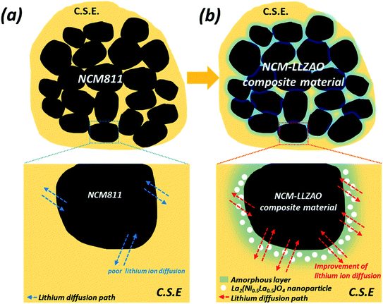
Therefore, in this study, the structure and electrochemical performance of NCM811 and NCM–LLZAO composite cathode material (LLZAO-0.2, LLZAO-0.5, and LLZAO-1.0) were investigated to study the effect of improving ionic and electrical conductivity encapsulated by amorphous garnet-type LLZAO SE and self-assembled La2(Ni0.5Li0.5)O4 nanoparticles to be used in ASSBs with oxide-based organic/inorganic CSE to address the interface issues. To optimize the amount of LLZAO, the composite cathode material was synthesized using the co-precipitation method with a LLZAO composition of 0.2, 0.5, and 1.0 wt%. A schematic diagram of the ASSBs using NCM811 and NCM–LLZAO composite cathode material is illustrated in Fig. 1. We manufactured the positive electrode and SE sheet using the organic/inorganic SE based on PEO binder to reduce the interfacial resistance, which is a drawback of ASSBs. Fig. 1 illustrates our concept about the NCM811 and NCM–LLZAO composite active material mixed CSEs present in the positive electrode. In ASSBs, lithium ion transfer occurs through the contact between SE and active material. The CSE mixed with the polymer and oxide-based SE leads to improved interfacial contact when compared with pellet type ASSBs composed of oxide-based SE. However, the lithium ion mobility is limited, as shown in Fig. 1(a) that shows the NCM811 sample. However, Fig. 1(b) demonstrates that the NCM–LLZAO cathode material exhibits an increased lithium ion mobility due to the synergy effect. This effect arises from the ionic conduction of amorphous LLZAO coating layer and La2(Ni0.5Li0.5)O4 nanoparticle with electrical conductivity. These materials were examined using powder X-ray diffraction (PXRD), field-emission scanning electron microscopy (FE-SEM), electrochemical impedance spectroscopy (EIS), and galvanostatic measurements to optimize the composition of LLZAO in the cathode material and determine the rationale to improve the electrochemical characteristic.
Experimental
Materials
Synthesis of NCM811 cathode material Ni0.8Co0.1Mn0.1(OH)2 (NCM811) precursor was synthesized using the co-precipitation method. The spherical precursor NCM811 was synthesized using the continuous-type co-precipitation method with LCTR-tera 3100 model equipment manufactured by Laminar Co., Ltd. The detailed synthesis conditions were presented in our previous paper.28,29 NCM–LLZAO composite cathode material The spherical composite precursor Ni0.8Co0.1Mn0.1(OH)2 and La3Zr2Al0.25(OH)x (NCM811–LZAOH) were synthesized using continuous-type co-precipitation method via a LCTR-tera 3100 system (Laminar Co., Ltd.). An NCM811–LZA aqueous solution consisting of NiSO4·6H2O, CoSO4·7H2O, MnSO4·5H2O, La(NO3)3·6H2O, ZrO(NO3)•xH2O, and Al(NO3)3·9H2O (molar ratio of Ni![[thin space (1/6-em)]](https://www.rsc.org/images/entities/char_2009.gif) :
:![[thin space (1/6-em)]](https://www.rsc.org/images/entities/char_2009.gif) Co
Co![[thin space (1/6-em)]](https://www.rsc.org/images/entities/char_2009.gif) :
:![[thin space (1/6-em)]](https://www.rsc.org/images/entities/char_2009.gif) Mn = 8
Mn = 8![[thin space (1/6-em)]](https://www.rsc.org/images/entities/char_2009.gif) :
:![[thin space (1/6-em)]](https://www.rsc.org/images/entities/char_2009.gif) 1
1![[thin space (1/6-em)]](https://www.rsc.org/images/entities/char_2009.gif) :
:![[thin space (1/6-em)]](https://www.rsc.org/images/entities/char_2009.gif) 1 and 0.2, 0.5, and 1.0 wt% of La
1 and 0.2, 0.5, and 1.0 wt% of La![[thin space (1/6-em)]](https://www.rsc.org/images/entities/char_2009.gif) :
:![[thin space (1/6-em)]](https://www.rsc.org/images/entities/char_2009.gif) Zr
Zr![[thin space (1/6-em)]](https://www.rsc.org/images/entities/char_2009.gif) :
:![[thin space (1/6-em)]](https://www.rsc.org/images/entities/char_2009.gif) Al = 3
Al = 3![[thin space (1/6-em)]](https://www.rsc.org/images/entities/char_2009.gif) :
:![[thin space (1/6-em)]](https://www.rsc.org/images/entities/char_2009.gif) 2
2![[thin space (1/6-em)]](https://www.rsc.org/images/entities/char_2009.gif) :
:![[thin space (1/6-em)]](https://www.rsc.org/images/entities/char_2009.gif) 0.25) was gradually pumped into a 1 L continuous-type reactor, where a suitable amount of a D.I. water, NH4OH, and NaOH solution was added without using an inert gas. Simultaneously, 4 mol L−1 NaOH solution (aq.) and NH4OH solution mixed with D.I water at a ratio of 1
0.25) was gradually pumped into a 1 L continuous-type reactor, where a suitable amount of a D.I. water, NH4OH, and NaOH solution was added without using an inert gas. Simultaneously, 4 mol L−1 NaOH solution (aq.) and NH4OH solution mixed with D.I water at a ratio of 1![[thin space (1/6-em)]](https://www.rsc.org/images/entities/char_2009.gif) :
:![[thin space (1/6-em)]](https://www.rsc.org/images/entities/char_2009.gif) 1 (aq.), as chelating agents, were separately pumped into the reactor. An NCM–LLZAO aqueous solution and NH4OH aqueous solution were pumped into the reactor at a flow rate of 2 ml min−1 and 0.5 ml min−1, respectively. The NaOH aqueous solution pump was connected to the sensor that adjusted the flow rate according to the pH value. We set the pH value at 11 and maintained 4 h of residence time. The pH, flow rate, and precipitate morphology were checked every 4 h. The precursor powder was obtained after washing, filtering, and drying at 100 °C for 6 h. The dried powder (NCM–LLZAO composite precursor) was calcined at 500 °C for 10 h, mixed with LiOH, and further calcined at 850 °C for 10 h in O2 atmosphere.
1 (aq.), as chelating agents, were separately pumped into the reactor. An NCM–LLZAO aqueous solution and NH4OH aqueous solution were pumped into the reactor at a flow rate of 2 ml min−1 and 0.5 ml min−1, respectively. The NaOH aqueous solution pump was connected to the sensor that adjusted the flow rate according to the pH value. We set the pH value at 11 and maintained 4 h of residence time. The pH, flow rate, and precipitate morphology were checked every 4 h. The precursor powder was obtained after washing, filtering, and drying at 100 °C for 6 h. The dried powder (NCM–LLZAO composite precursor) was calcined at 500 °C for 10 h, mixed with LiOH, and further calcined at 850 °C for 10 h in O2 atmosphere.
Structural and physical characterization
Electrochemical measurements
The electrochemical properties of the NCM811 and NCM–LLZAO composite cathode material were examined using lithium metal as reference and counter electrodes. The active material (NCM811 and NCM–LLZAO composite material), solid electrolyte (LLZAO), conductive carbon (super P), and polyethylene oxide (PEO, Mv: 200![[thin space (1/6-em)]](https://www.rsc.org/images/entities/char_2009.gif) 000) binder were used in a stoichiometric ratio of 70
000) binder were used in a stoichiometric ratio of 70![[thin space (1/6-em)]](https://www.rsc.org/images/entities/char_2009.gif) :
:![[thin space (1/6-em)]](https://www.rsc.org/images/entities/char_2009.gif) 5:5
5:5![[thin space (1/6-em)]](https://www.rsc.org/images/entities/char_2009.gif) :
:![[thin space (1/6-em)]](https://www.rsc.org/images/entities/char_2009.gif) 20/75
20/75![[thin space (1/6-em)]](https://www.rsc.org/images/entities/char_2009.gif) :
:![[thin space (1/6-em)]](https://www.rsc.org/images/entities/char_2009.gif) 0:5
0:5![[thin space (1/6-em)]](https://www.rsc.org/images/entities/char_2009.gif) :
:![[thin space (1/6-em)]](https://www.rsc.org/images/entities/char_2009.gif) 20 to fabricate the electrode. LLZAO in the positive electrode improves the lithium ion conductivity of the electrode and provides a path through which lithium ion can move. The stoichiometrically mixed slurry was cast onto Al foil and then dried at 25 °C over 12 h to form the cathode. A 2032 coin-type cell, consisting of the cathode (14ϕ) and lithium-metal anode (16ϕ) separated by the composite membrane sheet (19ϕ) (prepared as described earlier), was fabricated in a dry room and aged for 12 h prior to the electrochemical experiment. The charge–discharge measurements of the fabricated coin-type cell were performed over the potential range 2.5–4.0 V vs. Li0/Li+ at different current densities using Wonatech WBCS 3000 L.
20 to fabricate the electrode. LLZAO in the positive electrode improves the lithium ion conductivity of the electrode and provides a path through which lithium ion can move. The stoichiometrically mixed slurry was cast onto Al foil and then dried at 25 °C over 12 h to form the cathode. A 2032 coin-type cell, consisting of the cathode (14ϕ) and lithium-metal anode (16ϕ) separated by the composite membrane sheet (19ϕ) (prepared as described earlier), was fabricated in a dry room and aged for 12 h prior to the electrochemical experiment. The charge–discharge measurements of the fabricated coin-type cell were performed over the potential range 2.5–4.0 V vs. Li0/Li+ at different current densities using Wonatech WBCS 3000 L.
Electrochemical impedance spectroscopy (EIS) was conducted at room temperature using a Bio-Logic Science instrument (SP-240) to determine variations in resistance in the assembled coin cell. The cell was tested at the 1st and 50th cycles and examined at each cycle over 100 MHz–1.0 MHz frequency range.
Lithium diffusion properties in the NCM811 and NCM–LLZAO composite positive electrode were investigated using the galvanostatic intermittent titration technique (GITT). The GITT steps consist of galvanostatic pulses of 10 mAg−1 for 10 min between 2.5 V–4.0 V vs. Li/Li+. Rests were included with a 10 min interval rests, and no current passing through the cell. All the electrochemical measurements were conducted at 70 °C using the Bio-Logic Science instrument (SP-240).
Results and discussion
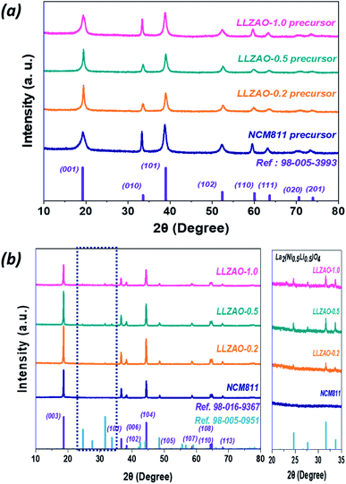
Fig. 2 shows the PXRD pattern of the NCM811 and NCM–LLZAO composite (LLZAO-0.2, LLZAO-0.5, and LLZAO-1.0) samples. Fig. 2(a) shows the PXRD of precursor samples synthesized using simultaneous co-precipitation method. All samples are indexed to a hexagonal structure and space group of p3m1, respectively. In the precursor samples demonstrate no impurity and peak shift. The PXRD patterns of the NCM811 and NCM–LLZAO composite material (LLZAO-0.2, LLZAO-0.5, and LLZAO-1.0) samples after calcination of 850 °C are shown in Fig. 2(b). NCM811 and NCM–LLZAO composite cathode materials are indexed to a hexagonal structure (space group: R3-m). Among them, NCM811 sample indicates no impurity and peak shift. This result shows that all conditions are suitable for the synthesis of NCM811. However, in the NCM–LLZAO composite samples, between 20 and 35°, there are four minor peaks that can only be found in LLZAO-0.2, LLZAO-0.5, and LLZAO-1.0, which are indexed to the La2(Li0.5Ni0.5)O4 with the K2NiF4-type structure. Further, as the LLZAO content of composite cathode material increases, magnitude of intensity for the minor impurity peak increases. During the calcination at a high temperature using mixed LLZAO precursor powder, Ni ion present on the surface of the NCM811 and La ion arising from the LLZAO precursor combined with residual lithium materials from excess amount of lithium source to form the La2(Ni0.5Li0.5)O4 material. The K2NiF4-type La2(Ni0.5Li0.5)O4 material with A2BO4 crystal structure has better electrical conductivity than perovskite ABO3 crystal structure.30 P. Ghosh et al. reported that La3+ doping induces structural stability of the LiCoO2 cathode material and serves as a solid electrolyte for Li+ ions dye in the presence of La2(Li0.5Co0.5)O4 in the ion conducting phase.31 Furthermore, A2BO4 crystal structure-type La2(Li0.5Co0.5)O4 material with high ionic conductivity of 1.1 × 10⁻³ s cm−1 contributes to improving the electrochemical performance by promoting lithium ion diffusion in the bulk cathode material. Table 1 shows the Rietveld refinement result of NCM811 and NCM–LLZAO composite cathode material XRD pattern. The c/3a ratio and I(003)/I(104) ratio have been reported to be an indication of cation ordering of the layered structure cathode materials.32 For a pure hexagonal closed packed structure in which Ni and Li atoms are fully disordered, the value of c/3a is 1.633. A greater c/3a ratio suggests a more ordered structure. Further, the intensity ratio, R-factor, of I(003)/I(104) represents the degree of cation disorder for Ni-based cathode material due to similar ionic radius of Ni2+ (0.69 Å). Li+ (0.76 Å) causes the cation mixing during the Li+ intercalation/de-intercalation. When the R-factor is less than 1.2, Ni2+ ions occupy the Li+ ion site, which indicates that the material exhibits poor structural characteristics.32,33| Sample | a (Å) | c (Å) | c/a | I003/I104 ratio |
|---|---|---|---|---|
| NCM811 | 2.8694 | 14.1957 | 4.9472 | 1.5046 |
| LLZAO-0.2 | 2.8696 | 14.1984 | 4.9478 | 1.5128 |
| LLZAO-0.5 | 2.8707 | 14.2012 | 4.9469 | 1.5896 |
| LLZAO-1.0 | 2.8752 | 14.2107 | 4.9426 | 1.5037 |
The potentiometric titration experiment was conducted to confirm the effect of the K2NiF4-type La2(Ni0.5Li0.5)O4 material on the reduction of residual lithium compounds of Li2CO3 and LiOH on the surface of NCM811 and NCM–LLZAO composite cathode materials. The corresponding results are shown in Table 2. The value of residual lithium on the cathode material surface was analyzed using potentiometric titration at 25 °C. The values of Li2CO3 and LiOH, which represent residual lithium on the cathode material surface, tend to decrease in the NCM–LLZAO composite cathode material when compared to that of the NCM811 cathode material. XRD pattern showed that the La2(Ni0.5Li0.5)O4 material was present as an impurity phase in the NCM811 cathode material. However, it contributed to removing residual lithium on the cathode material surface because La2(Ni0.5Li0.5)O4 material is formed with Ni in the cathode material, and La in the LLZAO and the excess Li sources arising from lithium volatilization during calcination process. It may improve the electrochemical properties of the NCM–LLZAO composite cathode material owing to its electrical conductivity.
| Sample | Li2CO3 (ppm) | LiOH (ppm) |
|---|---|---|
| NCM811 | 647 | 520 |
| LLZO-0.2 | 244 | 350 |
| LLZO-0.5 | 219 | 280 |
| LLZO-1.0 | 228 | 320 |
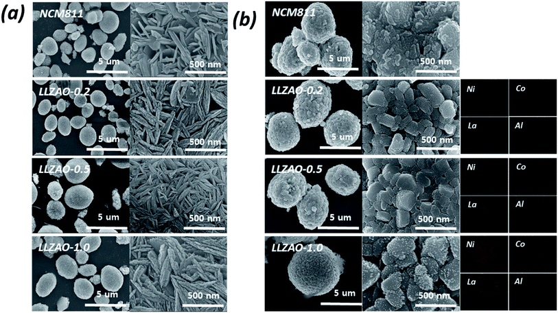
The morphology and homogeneous distribution of the NCM811 and NCM–LLZAO composite materials (LLZAO-0.2, LLZAO-0.5, and LLZAO-1.0) were investigated using FE-SEM (Fig. 3(a) and (b)); Fig. 3(a) shows the precursor sample synthesized via co-precipitation. All cathode material precursor produced via co-precipitation reaction form spherical secondary particles of approximately 5 μm size. Needle-shaped primary particles of 2–300 nm aggregate to form spherical secondary particles. The shape of the primary particles of the composite cathode material precursor obtained through simultaneous co-precipitation with the NCM811 precursor did not change significantly. The particle shape of the cathode material after calcination at 850 °C is shown in Fig. 3(b). After the calcination process, the shape of the primary particle grows while the spherical shape of the secondary particle is maintained. In addition, as a result of EDX mapping analysis, Ni and Co elements from the cathode material and La and Al elements from the ion conductive material were mixed in the composite cathode material obtained through simultaneous co-precipitation.
To further analyze the crystallographic characteristic of NCM811 and NCM–LLZAO composite cathode materials, FE-TEM images under low and high magnification were obtained as shown in Fig. 4. Primary particles of 100–200 nm were aggregated in the NCM811 and NCM–LLZAO composite cathode materials. Fig. 4 shows the characteristic crystal plane of the Li(Ni0.8Co0.1Mn0.1)O2 (NCM811) layered structure; the calculated planes were similar to those of the XRD patterns. An interplanar distance of 0.23 nm, calculated from the highly magnified images, corresponds to the (012) plane. This demonstrates that the NCM811 material was synthesized well using the co-precipitation method. TEM images of the NCM–LLZAO composite cathode material samples indicated an interplanar distance of 0.47 nm, which corresponds to the (003) plane. The TEM images at high magnification showed a difference in the surface area between NCM811 and NCM–LLZAO composite cathode materials. As the LLZAO content in the NCM–LLZAO composite cathode material increases, the thickness of amorphous coating layer on surface tends to gradually grow. Moreover, when the content of LLZAO is more than 0.5 wt% in the composite cathode material, small spherical nanoparticles with a size of 1–2 mm and an amorphous layer on the composite cathode material surface were observed. The interplanar distance of the nanoparticles was calculated to be 0.283 nm, which corresponds to the (103) plane of the La2(Ni0.5Li0.5)O4 material. The cathode materials synthesized via the simultaneous co-precipitation were investigated using dark field images and EDS mapping to obtain the distribution of component chemical element. The signal of Ni and Co appeared in the NCM811 cathode material, while the signal of La and Zr, which are components of LLZAO material, were additionally displayed in the composite cathode materials. This result indicates that the LLZAO material coating was present uniformly. LLZAO peak was not found in the XRD pattern of the composite cathode material. However, through FE-TEM and EDX mapping, the LLZAO material was directly confirmed through the uniform presence of La and Zr elements on the surface. This result confirms the presence of an amorphous coating layer on the surface of the LLZAO material and the composite cathode material with an ionic conductive material was synthesized satisfactorily.
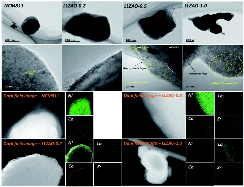 | ||
| Fig. 4 TEM images under low and high magnification of NCM811 and NCM–LLZAO composite cathode material calcined at 850 °C, showing dark field images of NCM811 and NCM–LLZAO composite cathode. | ||
The XPS analysis of the NCM811 and NCM–LLZAO composite cathode material was performed to investigate the chemical effect of the K2NiF4-type La2(Ni0.5Li0.5)O4 on NCM811 cathode material, as shown in Fig. 5. Fig. 5 shows the XPS peaks for Ni (2p) and La (3d) of NCM811 and NCM–LLZAO composite cathode material. Ni 2p 3/2 peaks show the chemical states for binding energy of the Ni2+ (853.6 eV) and Ni3+ (855.7 eV) ions, respectively. The XPS result shows that the ratio of Ni3+![[thin space (1/6-em)]](https://www.rsc.org/images/entities/char_2009.gif) :
:![[thin space (1/6-em)]](https://www.rsc.org/images/entities/char_2009.gif) Ni2+ in Ni 2p3/2 gradually increases as the LLZAO content in the composite cathode material increases when compared with that of the NCM811 material. Because of the La2(Ni0.5Li0.5)O4 material, Ni ion forms +3 valence on the NCM811 cathode material by combining with the La ion from the LLZAO. Further, Ni arises from NCM811 during the high temperature calcination process. This enlarged Ni3+ ion contributes in reducing the proportion of Ni2+/Li+ cation mixing during the synthesis process, which is similar to the Rietveld refinement shown in Table 1. The XPS signal of La 3d shows that NCM811 does not show binding energy signal for La 3 d. However, the peak of the La 3 d binding energy gradually appears as the content of the LLZAO in cathode material increases. La 3 d represents the binding energy of La2O3; it is represented by the bonding between La–O present in the La2(Ni0.5Li0.5)O4 material on the composite cathode material surface.
Ni2+ in Ni 2p3/2 gradually increases as the LLZAO content in the composite cathode material increases when compared with that of the NCM811 material. Because of the La2(Ni0.5Li0.5)O4 material, Ni ion forms +3 valence on the NCM811 cathode material by combining with the La ion from the LLZAO. Further, Ni arises from NCM811 during the high temperature calcination process. This enlarged Ni3+ ion contributes in reducing the proportion of Ni2+/Li+ cation mixing during the synthesis process, which is similar to the Rietveld refinement shown in Table 1. The XPS signal of La 3d shows that NCM811 does not show binding energy signal for La 3 d. However, the peak of the La 3 d binding energy gradually appears as the content of the LLZAO in cathode material increases. La 3 d represents the binding energy of La2O3; it is represented by the bonding between La–O present in the La2(Ni0.5Li0.5)O4 material on the composite cathode material surface.
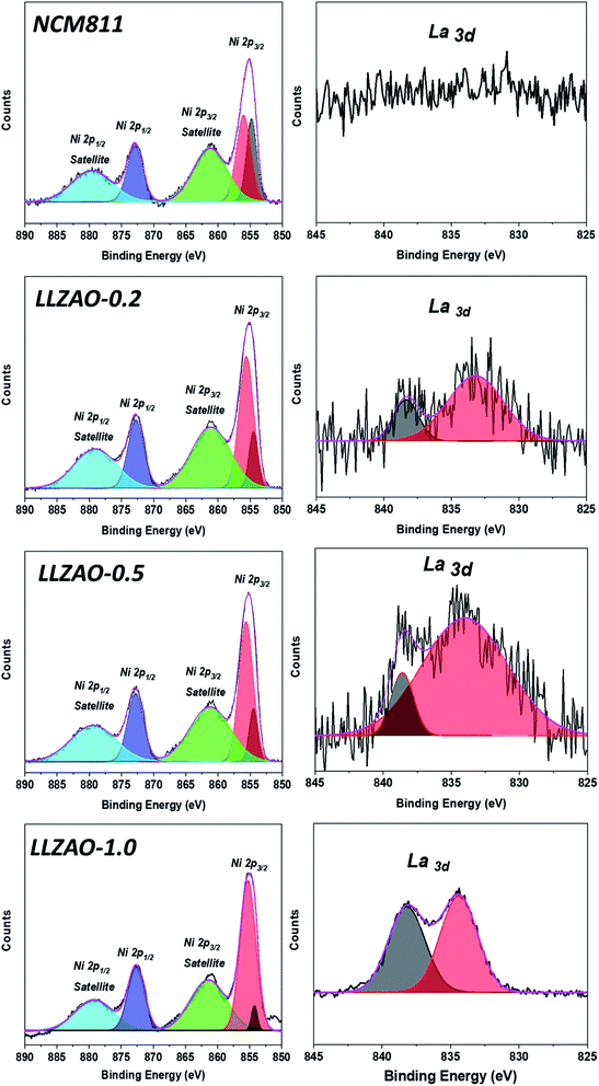 | ||
| Fig. 5 XPS spectra for Ni 2p and La 3d of NCM811 and NCM–LLZAO composite cathode materials. The black line represents the experimental data while the other lines represent the fitting result. | ||
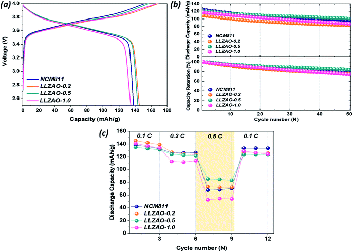
Electrochemical properties were evaluated by assembling 2032 coin cell with the positive electrode that is composed of NCM811 and NCM–LLZAO composite electrode vs. Li0/Li+. To exclude the unfavorable influence of the PEO binder in the positive electrode, Li+ ion had to be extracted from the NCM811 and NCM–LLZAO composite electrodes at less than 4.0 V vs. Li0/Li+ owing to the restricted stability of the PEO binder in ASSBs, which cannot exceed 4.0 V vs. Li0/Li+.23 Considering the LiB system that contains liquid electrolyte, lithium ions move freely throughout the positive electrode owing to the fluid properties of liquid electrolyte. However, in ASSBs system that does not use a liquid electrolyte, a solid electrolyte is added to increase the lithium ion mobility into the positive electrode because lithium ions move in the lattice. Fig. 6 demonstrates the electrochemical performance of positive electrode synthesized by combining NCM811 and NCM–LLZAO composite active material, conductive material, LLZAO solid electrolyte, and PEO binder at a ratio of 70![[thin space (1/6-em)]](https://www.rsc.org/images/entities/char_2009.gif) :
:![[thin space (1/6-em)]](https://www.rsc.org/images/entities/char_2009.gif) 5
5![[thin space (1/6-em)]](https://www.rsc.org/images/entities/char_2009.gif) :
:![[thin space (1/6-em)]](https://www.rsc.org/images/entities/char_2009.gif) 5
5![[thin space (1/6-em)]](https://www.rsc.org/images/entities/char_2009.gif) :
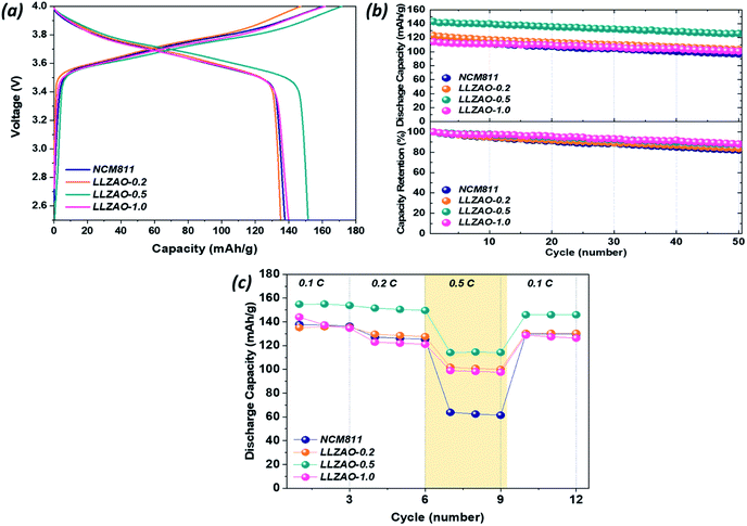
:![[thin space (1/6-em)]](https://www.rsc.org/images/entities/char_2009.gif) 20. Fig. 6(a) shows initial charge/discharge curves of all positive electrodes measured at 0.1C (1C = 170 mA h g−1) and indicates their initial discharge capacities of 138.17, 145.34, 143.51, and 134.78 mA h g−1, respectively. The initial discharge capacity of composite cathode material is higher than that of NCM811. Fig. 6(b) shows the cyclability of NCM811 and composite cathode material at a current density at 0.2C. After 50 cycles, all cathode materials show a high discharge capacity retention over 70%. Among them, LLZAO-0.5 showed a capacity retention rate of 83.78%, which is much higher than that of NCM811 (77.45%). The rate capability of all positive electrodes were measured at various current density at 0.1–0.5C and presented in Fig. 6(c). This result indicates that the discharge capacity of all cathode materials is gradually decreasing. As the current density increases, the composite cathode material exhibits higher discharge capacity than that of the NCM811 material. Particularly, the LLZAO-0.5 material demonstrates improved electrochemical performance when compared to the NCM811 sample under various current densities. As the current density increases at 0.5C, the capacity retention ratio of the two electrodes shows a large difference. In the NCM811 sample, the discharge capacity retention is shown to be approximately 50%. However, in the LLZAO-0.5 sample, the discharge capacity retention was 63%, which indicates better discharge capacity retention; all values are listed in Table 3. Because an LLZAO with high ionic conductivity is present on the NCM811 surface and contributes to improving the lithium ion diffusion from the active material to CSE in the positive electrode.28,29 In addition, La2(Ni0.5Li0.5)O4 nanoparticles present on the cathode material surface exhibit electrical conductivity, which seems to contribute to the increase in the initial discharge capacity of the NCM–LLZAO composite cathode material.30
20. Fig. 6(a) shows initial charge/discharge curves of all positive electrodes measured at 0.1C (1C = 170 mA h g−1) and indicates their initial discharge capacities of 138.17, 145.34, 143.51, and 134.78 mA h g−1, respectively. The initial discharge capacity of composite cathode material is higher than that of NCM811. Fig. 6(b) shows the cyclability of NCM811 and composite cathode material at a current density at 0.2C. After 50 cycles, all cathode materials show a high discharge capacity retention over 70%. Among them, LLZAO-0.5 showed a capacity retention rate of 83.78%, which is much higher than that of NCM811 (77.45%). The rate capability of all positive electrodes were measured at various current density at 0.1–0.5C and presented in Fig. 6(c). This result indicates that the discharge capacity of all cathode materials is gradually decreasing. As the current density increases, the composite cathode material exhibits higher discharge capacity than that of the NCM811 material. Particularly, the LLZAO-0.5 material demonstrates improved electrochemical performance when compared to the NCM811 sample under various current densities. As the current density increases at 0.5C, the capacity retention ratio of the two electrodes shows a large difference. In the NCM811 sample, the discharge capacity retention is shown to be approximately 50%. However, in the LLZAO-0.5 sample, the discharge capacity retention was 63%, which indicates better discharge capacity retention; all values are listed in Table 3. Because an LLZAO with high ionic conductivity is present on the NCM811 surface and contributes to improving the lithium ion diffusion from the active material to CSE in the positive electrode.28,29 In addition, La2(Ni0.5Li0.5)O4 nanoparticles present on the cathode material surface exhibit electrical conductivity, which seems to contribute to the increase in the initial discharge capacity of the NCM–LLZAO composite cathode material.30
![[thin space (1/6-em)]](https://www.rsc.org/images/entities/char_2009.gif) :
:![[thin space (1/6-em)]](https://www.rsc.org/images/entities/char_2009.gif) 5
5![[thin space (1/6-em)]](https://www.rsc.org/images/entities/char_2009.gif) :
:![[thin space (1/6-em)]](https://www.rsc.org/images/entities/char_2009.gif) 5
5![[thin space (1/6-em)]](https://www.rsc.org/images/entities/char_2009.gif) :
:![[thin space (1/6-em)]](https://www.rsc.org/images/entities/char_2009.gif) 20
20
| Sample | 1st capacity (mA h g−1) | Capacity retention (%) | Capacity retention (%) | ||
|---|---|---|---|---|---|
| 0.1C | 0.2C | 0.5C | |||
| NCM 811 | 138.17 | 77.45 | 100 | 90.67 | 51.05 |
| LLZAO-0.2 | 145.34 | 75.84 | 100 | 97.32 | 50.17 |
| LLZAO-0.5 | 143.51 | 83.78 | 100 | 91.92 | 63.12 |
| LLZAO-1.0 | 134.78 | 73.99 | 100 | 79.72 | 37.22 |
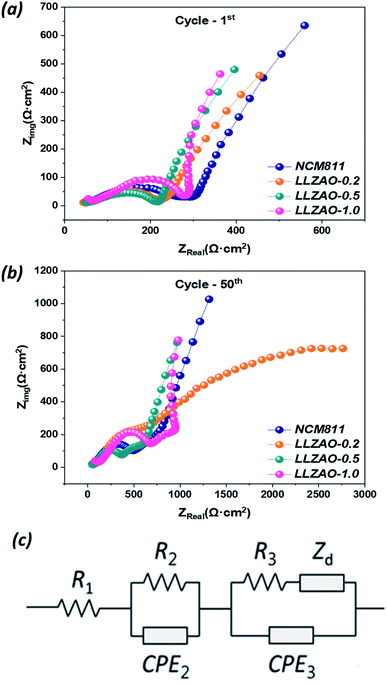
To further understand the effect of the La2(Ni0.5Li0.5)O4 nanoparticles and LLZAO coating layer on the cathode surface during the cycling in an assembled coin cell, the following analysis has been conducted. Fig. 7 shows the EIS spectra of the assembled coin cell (Al/NCM811 or NCM–LLZAO composite material//PEO–LLZO–LiClO4//Li-metal) recorded in the 100 MHz–1 MHz range, for the 1st and 50th cycles. The Nyquist plots show conventional semicircles at high and medium frequencies and an inclined line in the low-frequency region that corresponds to the interfacial resistance associated with the lithium-ion diffusion in the bulk material. Rb, Rs, and Rct represent the bulk resistance of the cell (electrolyte and electrode), interfacial resistance, and charge transfer resistance, respectively. The lithium-ion diffusion through the interface between the cathode and SE (Rs) is reflected in the first semicircle. The second semicircle is associated with charge-transfer resistance (Rct). The measured impedance spectra were quantitatively analyzed using the equivalent circuit in Fig. 7. In the equivalent circuit, R1 represents the contact resistance, R2 and CPE2 represent the resistance and constant phase element for surface films, respectively, R3 and CPE3 represent the charge-transfer resistance and constant phase element for double-layer charging/discharging, respectively, and Zd represents the diffusion impedance.34 Fig. 7 demonstrates that the interfacial resistance of composite cathode material is gradually lowered in both initial cycle and after 50 cycles as the content of LLZAO material increases when compared to that of NCM811 cathode material. This impedance result reveals that electrochemical properties of ASSBs are significantly related to the cathode material; this was observed in terms of the significant reduction in impedance of the cell with LLZAO-0.5 cathode material. This result shows that the interfacial resistance between the active material and solid electrolyte is reduced because of the presence of the La2(Ni0.5Li0.5)O4 nanoparticles with electrical conductivity and LLZAO coating layer with high ionic conductivity on the composite cathode material surface.
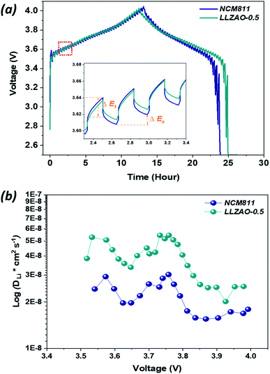
To further analyze the difference in the electrochemical performance of LLZAO-0.5 and NCM811, which have excellent electrochemical properties among composite cathode materials, GITT analysis was performed at the rate of 10 mA g−1 in the specified working voltage region (OCV = 4.0 V) for the first cycle (Fig. 8(a)), with an equal interval of pulses (10 min); the rest time was fixed as 10 min to reach a quasi–electrochemical equilibrium voltage measured at SP-240 equipment. The result of single titration output during the cycling process for the NCM811 and LLZAO-0.5 cathodes are illustrated in the inset of Fig. 8. The transient potential response demonstrated in the GITT results can be used to calculate the lithium ion diffusion coefficient according to Fick's second law:
| D*Li = 4/(π × τ)((mb × Vm)/(Mb × S))2(ΔEs/ΔEτ)2 | (1) |
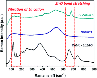
To analyze the LLZAO layer present on the composite cathode material surface, Raman spectroscopy was conducted to confirm the crystalline structure of the NCM811 and LLZAO-0.5 cathode material as shown in Fig. 9. To gain specific information regarding the NCM811, LLZAO-0.5, and LLZAO, the cubic-LLZAO material (manufactured by TOSIMA) were investigated. Considering the LLZAO-0.5 sample, the corresponding peaks of NCM811 and cubic-LLZAO signal were mixed. First, a Raman shift at 550 cm−1 assigned to NCM811 appeared in the LLZAO-0.5 sample.37 Then, the intensity associated with the La cation vibration was observed at 100–150 cm−1 Raman shift; the signal corresponding to the stretching of the Zr–O bond occurred at approximately 640 cm−1.38,39 Although, the intensity is low in the LLZAO-0.5 sample, the signal for cubic-LLZAO can be observed. Raman spectroscopy results indicate that LLZAO and NCM811 were mixed and the layer present on the LLZAO-0.5 surface is an amorphous LLZAO layer.
The presence of an SE in the positive electrode is related to the electrochemical performance in an ASSBs system. The SE within the positive electrode plays an important role for lithium ions to efficiently migrate from the positive electrode to the negative electrode similar to a liquid electrolyte in LiBs system. To confirm the improvement of electrochemical performance due to the effect of increasing ionic conductivity on the LLZAO coating layer present on the cathode material surface; with the absence of the solid electrolyte in the positive electrode, the ratio of active material, solid electrolyte, conductive material and binder was designed to 75![[thin space (1/6-em)]](https://www.rsc.org/images/entities/char_2009.gif) :
:![[thin space (1/6-em)]](https://www.rsc.org/images/entities/char_2009.gif) 0:5
0:5![[thin space (1/6-em)]](https://www.rsc.org/images/entities/char_2009.gif) :
:![[thin space (1/6-em)]](https://www.rsc.org/images/entities/char_2009.gif) 20, as shown in Fig. 10. Fig. 10(a) shows the initial charge/discharge curves of NCM811 and composite cathode material samples measured at 0.1C (1C = 170 mA h g−1) and indicates their initial discharge capacities of 137.04, 135.16, 151.50, and 139.85 mA h g−1, respectively. The initial discharge capacity of composite cathode material is higher than that of the NCM811. Fig. 10(b) shows the cyclability of the NCM811 and composite cathode material at a current density at 0.2C. After 50 cycles, all cathode materials showed a high discharge capacity retention of more than 80%. Among them, the LLZAO-0.5 showed a capacity retention rate of 87.98%, which was much higher than that of the NCM811 (82.06%). The rate capability of all positive electrodes were measured at various current densities of 0.1–0.5C and are presented in Fig. 10(c). This result indicated that the discharge capacity of all cathode materials is gradually decreasing. As the current density increases, the composite cathode material exhibits higher discharge capacity than that of the NCM811 material even though solid electrolyte was absent in the electrode. Particularly, the LLZAO-0.5 material showed improved electrochemical performance when compared to the NCM811 sample under various current densities. As the current density increases at 0.5C, the capacity retention ratio of the two electrodes shows a large difference. In the NCM811 sample, the discharge capacity retention is shown to be approximately less than 50%. However, in the LLZAO-0.5, the discharge capacity retention was 73%, which indicates better discharge capacity retention; all values are listed in Table 4. Because of the presence of LLZAO with high ionic conductivity on the NCM811 surface, there is an improved lithium ion diffusion from the active material to CSE in the positive electrode. Moreover, La2(Ni0.5Li0.5)O4 nanoparticles present on the cathode material surface exhibit electrical conductivity, which seems to contribute to the improvement of rate capability of NCM–LLZAO composite cathode material, particularly the LLZAO-0.5 sample without an SE in the positive electrode.31
20, as shown in Fig. 10. Fig. 10(a) shows the initial charge/discharge curves of NCM811 and composite cathode material samples measured at 0.1C (1C = 170 mA h g−1) and indicates their initial discharge capacities of 137.04, 135.16, 151.50, and 139.85 mA h g−1, respectively. The initial discharge capacity of composite cathode material is higher than that of the NCM811. Fig. 10(b) shows the cyclability of the NCM811 and composite cathode material at a current density at 0.2C. After 50 cycles, all cathode materials showed a high discharge capacity retention of more than 80%. Among them, the LLZAO-0.5 showed a capacity retention rate of 87.98%, which was much higher than that of the NCM811 (82.06%). The rate capability of all positive electrodes were measured at various current densities of 0.1–0.5C and are presented in Fig. 10(c). This result indicated that the discharge capacity of all cathode materials is gradually decreasing. As the current density increases, the composite cathode material exhibits higher discharge capacity than that of the NCM811 material even though solid electrolyte was absent in the electrode. Particularly, the LLZAO-0.5 material showed improved electrochemical performance when compared to the NCM811 sample under various current densities. As the current density increases at 0.5C, the capacity retention ratio of the two electrodes shows a large difference. In the NCM811 sample, the discharge capacity retention is shown to be approximately less than 50%. However, in the LLZAO-0.5, the discharge capacity retention was 73%, which indicates better discharge capacity retention; all values are listed in Table 4. Because of the presence of LLZAO with high ionic conductivity on the NCM811 surface, there is an improved lithium ion diffusion from the active material to CSE in the positive electrode. Moreover, La2(Ni0.5Li0.5)O4 nanoparticles present on the cathode material surface exhibit electrical conductivity, which seems to contribute to the improvement of rate capability of NCM–LLZAO composite cathode material, particularly the LLZAO-0.5 sample without an SE in the positive electrode.31
![[thin space (1/6-em)]](https://www.rsc.org/images/entities/char_2009.gif) :
:![[thin space (1/6-em)]](https://www.rsc.org/images/entities/char_2009.gif) 0
0![[thin space (1/6-em)]](https://www.rsc.org/images/entities/char_2009.gif) :
:![[thin space (1/6-em)]](https://www.rsc.org/images/entities/char_2009.gif) 5
5![[thin space (1/6-em)]](https://www.rsc.org/images/entities/char_2009.gif) :
:![[thin space (1/6-em)]](https://www.rsc.org/images/entities/char_2009.gif) 20
20
| Sample | 1st capacity (mAh g−1) | Capacity retention (%) | Capacity retention (%) | ||
|---|---|---|---|---|---|
| 0.1C | 0.2C | 0.5C | |||
| NCM 811 | 137.04 | 82.06 | 100 | 92.35 | 46.35 |
| LLZAO-0.2 | 135.16 | 86.68 | 100 | 95.85 | 75.29 |
| LLZAO-0.5 | 151.50 | 87.98 | 100 | 97.87 | 73.70 |
| LLZAO-1.0 | 139.85 | 88.17 | 100 | 85.37 | 68.75 |
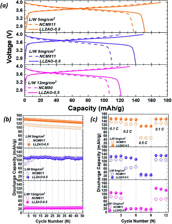
ASSBs with high energy density must satisfy various requirements, such as high capacity cathode materials, positive electrode manufactured with high loading weight, and high proportion of an active material in the positive electrode, etc. The electrochemical properties of the cathode material improved even when the ratio of the SE in the positive electrode was zero. To realize the high energy density characteristic of ASSBs, the loading weight of NCM811 and LLZAO-0.5 electrodes were designed as 5, 8, and 12 mg cm−2. The active material ratio in positive electrode was prepared at 75 wt% (75![[thin space (1/6-em)]](https://www.rsc.org/images/entities/char_2009.gif) :
:![[thin space (1/6-em)]](https://www.rsc.org/images/entities/char_2009.gif) 0
0![[thin space (1/6-em)]](https://www.rsc.org/images/entities/char_2009.gif) :
:![[thin space (1/6-em)]](https://www.rsc.org/images/entities/char_2009.gif) 5
5![[thin space (1/6-em)]](https://www.rsc.org/images/entities/char_2009.gif) :
:![[thin space (1/6-em)]](https://www.rsc.org/images/entities/char_2009.gif) 20) to evaluate the electrochemical properties and shown in Fig. 11. Fig. 11(a) shows the initial charge/discharge curves for the NCM811 and LLZAO-0.5 samples as the loading weight increased. In ASSBs, as the loading weight increases, the thickness of positive electrode increases; hence, the initial discharge capacity gradually decreases. In addition, LLZAO-0.5 sample exhibited a higher initial discharge capacity when compared to the NCM811 sample for all loading weights. This result shows that the initial discharge capacity has increased owing to the improved lithium ion diffusion with LLZAO material present on the cathode material surface even when the loading weight was increased. Fig. 11(b) shows the result of comparing the cyclability of the NCM811 and LLZAO-0.5 samples with a current density of 0.2C during 50 cycles. The figure demonstrates that the discharge capacity gradually decreases as the loading weight increases. Consider the loading weight of 5 mg cm−2, the discharge capacity of NCM811 and LLZAO-0.5 were found to be 117.95 mA h g−1 and 143.18 mA h g−1, respectively, and discharge capacity retention were maintained at 82.06% and 87.98% after 50 cycles, respectively. However, in the increased load weight of 8 mg cm−2, initial discharge capacity of NCM811 and LLZAO-0.5 decreased to 81.62 mA h g−1 and 111.81 mA h g−1, respectively. At the higher loading weight of 12 mg cm−2 for NCM811 and LLZAO-0.5, the initial discharge capacity for the measured current density of 0.1C showed discharge capacities of 107.19 and 121.65 mA h g−1 (Fig. 11(a)), respectively; however, both samples showed significant capacity loss of approximately 32.25 and 22.73 mA h g−1, respectively. As the loading weight of positive electrode increases, the concentration gradient of lithium ions becomes larger as it moves away from the surface of positive electrode. From this phenomenon, a lithium ion deficiency occurs and resistance increases rapidly; a dead zone is formed in the positive electrode where the lithium ion are present but cannot participate in the charge/discharge process. This causes deterioration due to internal resistance, resulting in a decrease in the discharge capacity. The rate capability of NCM811 and LLZAO-0.5 for various current densities at 0.1–0.5C are shown in Fig. 11(c). In 5 mg cm−2, the difference in the discharge capacity does not appear significantly at low current densities of 0.1–0.2C. However, discharge capacity of NCM811 is significantly reduced when compared to LLZAO-0.5. At the increased loading weight of 8 mg cm−2, discharge capacity of NCM811 and LLZAO-0.5 indicate a large difference at a low current density of 0.2C unlike in the case where the loading weight is 5 mg cm−2. At a current density of 0.5C, both samples show a low capacity of approximately 22.06 and 29.61 mA h g−1, respectively. For the loading weight of 12 mg cm−2, the difference in capacity between the NCM811 and LLZAO-0.5 was large at a discharge capacity of 0.1C, and both samples deteriorated at the current density of more than 0.2C. This phenomenon shows that an inactive zone was formed inside the positive electrode, and the effect of internal resistance increases with an increase in the loading weight. However, LLZAO coating layer and La2(Ni0.5Li0.5)O4 nanoparticles present on the surface of the composite anode material exhibiting ionic and electrical conductivity show an improvement in the mobility of lithium ions for LLZAO-0.5 sample. The electrochemical properties improved even if there was no SE in the electrode with an increase in the loading weight owing to the high lithium ion mobility. The NCM–LLZAO composite cathode material synthesized using co-precipitation is expected to be a starting point for improving the energy density characteristics of ASSBs.
20) to evaluate the electrochemical properties and shown in Fig. 11. Fig. 11(a) shows the initial charge/discharge curves for the NCM811 and LLZAO-0.5 samples as the loading weight increased. In ASSBs, as the loading weight increases, the thickness of positive electrode increases; hence, the initial discharge capacity gradually decreases. In addition, LLZAO-0.5 sample exhibited a higher initial discharge capacity when compared to the NCM811 sample for all loading weights. This result shows that the initial discharge capacity has increased owing to the improved lithium ion diffusion with LLZAO material present on the cathode material surface even when the loading weight was increased. Fig. 11(b) shows the result of comparing the cyclability of the NCM811 and LLZAO-0.5 samples with a current density of 0.2C during 50 cycles. The figure demonstrates that the discharge capacity gradually decreases as the loading weight increases. Consider the loading weight of 5 mg cm−2, the discharge capacity of NCM811 and LLZAO-0.5 were found to be 117.95 mA h g−1 and 143.18 mA h g−1, respectively, and discharge capacity retention were maintained at 82.06% and 87.98% after 50 cycles, respectively. However, in the increased load weight of 8 mg cm−2, initial discharge capacity of NCM811 and LLZAO-0.5 decreased to 81.62 mA h g−1 and 111.81 mA h g−1, respectively. At the higher loading weight of 12 mg cm−2 for NCM811 and LLZAO-0.5, the initial discharge capacity for the measured current density of 0.1C showed discharge capacities of 107.19 and 121.65 mA h g−1 (Fig. 11(a)), respectively; however, both samples showed significant capacity loss of approximately 32.25 and 22.73 mA h g−1, respectively. As the loading weight of positive electrode increases, the concentration gradient of lithium ions becomes larger as it moves away from the surface of positive electrode. From this phenomenon, a lithium ion deficiency occurs and resistance increases rapidly; a dead zone is formed in the positive electrode where the lithium ion are present but cannot participate in the charge/discharge process. This causes deterioration due to internal resistance, resulting in a decrease in the discharge capacity. The rate capability of NCM811 and LLZAO-0.5 for various current densities at 0.1–0.5C are shown in Fig. 11(c). In 5 mg cm−2, the difference in the discharge capacity does not appear significantly at low current densities of 0.1–0.2C. However, discharge capacity of NCM811 is significantly reduced when compared to LLZAO-0.5. At the increased loading weight of 8 mg cm−2, discharge capacity of NCM811 and LLZAO-0.5 indicate a large difference at a low current density of 0.2C unlike in the case where the loading weight is 5 mg cm−2. At a current density of 0.5C, both samples show a low capacity of approximately 22.06 and 29.61 mA h g−1, respectively. For the loading weight of 12 mg cm−2, the difference in capacity between the NCM811 and LLZAO-0.5 was large at a discharge capacity of 0.1C, and both samples deteriorated at the current density of more than 0.2C. This phenomenon shows that an inactive zone was formed inside the positive electrode, and the effect of internal resistance increases with an increase in the loading weight. However, LLZAO coating layer and La2(Ni0.5Li0.5)O4 nanoparticles present on the surface of the composite anode material exhibiting ionic and electrical conductivity show an improvement in the mobility of lithium ions for LLZAO-0.5 sample. The electrochemical properties improved even if there was no SE in the electrode with an increase in the loading weight owing to the high lithium ion mobility. The NCM–LLZAO composite cathode material synthesized using co-precipitation is expected to be a starting point for improving the energy density characteristics of ASSBs.
Conclusions
In summary, we investigated a NCM811 and NCM–LLZAO composite cathode material to be assembled in ASSBs with an oxide-based solid electrolyte. The XRD patterns of the NCM811 and NCM–LLZAO composite samples were indexed to a hexagonal structure each. However, in the 20°–35° region, the K2NiF4-type structure of the La2(Ni0.5Li0.5)O4 material was observed in NCM–LLZAO composite cathode material synthesized using simultaneous co-precipitation. Further, the potentiometric titration result shows that the ratio of residual lithium on the cathode material surface of the NCM–LLZAO composite cathode material decreases when compared with that of the NCM811. During calcination at a high temperature, the Ni ion present on the surface of NCM811 and the La ion from the LZAOH precursor combined with the residual lithium materials forming the La2(Ni0.5Li0.5)O4 material. In addition, a LLZAO coating layer exhibiting ion conductivity was present on the surface of composite cathode material; TEM images confirmed that the coating layer thickness increased as the LLZAO content in the composite cathode material increased. In the NCM–LLZAO composite cathode material, the electrochemical performance improved when compared with that of the NCM811 sample because L2(Ni0.5Li0.5)O4, which exists as a spherical nanoparticles on the surface of the composite cathode material, facilitates the movement of lithium ions at the interface between the solid electrolyte and cathode material within the positive electrode due to its high electrical conductivity. In particular, NCM–LLZAO composite cathode material demonstrated improved electrochemical properties when compared to that of the NCM811 even in the composition without a solid electrolyte in the electrode (75![[thin space (1/6-em)]](https://www.rsc.org/images/entities/char_2009.gif) :
:![[thin space (1/6-em)]](https://www.rsc.org/images/entities/char_2009.gif) 0
0![[thin space (1/6-em)]](https://www.rsc.org/images/entities/char_2009.gif) :
:![[thin space (1/6-em)]](https://www.rsc.org/images/entities/char_2009.gif) 5
5![[thin space (1/6-em)]](https://www.rsc.org/images/entities/char_2009.gif) :
:![[thin space (1/6-em)]](https://www.rsc.org/images/entities/char_2009.gif) 20). Among them, LLZAO-0.5 showed significantly enhanced electrochemical performance owing to high lithium ion diffusion coefficient. The electrochemical properties improved, even in the absence of solid electrolyte in the electrode, with an increase in the loading weight owing to the high lithium ion mobility. The NCM–LLZAO composite cathode material synthesized using co-precipitation is expected to be a starting point for improving the energy density characteristics of ASSBs. For ASSBs with high energy density, electrochemical characteristics are required even under high loading weight of positive electrode conditions. It has been confirmed that the composite cathode material contributes to the improvement of the characteristics of the ASSBs even if the amount of solid electrolyte is reduced in the electrode composition, which is a great advantage in realizing high energy density. However, at present, there is a limit to cell driving at electrode loading weight of 10 mg cm−2. For the high energy density of all-solid-state batteries, we believe that future research on high energy density of ASSBs is necessary by designing a cell composition that can be driven at over the loading weight of 10 mg cm−2.
20). Among them, LLZAO-0.5 showed significantly enhanced electrochemical performance owing to high lithium ion diffusion coefficient. The electrochemical properties improved, even in the absence of solid electrolyte in the electrode, with an increase in the loading weight owing to the high lithium ion mobility. The NCM–LLZAO composite cathode material synthesized using co-precipitation is expected to be a starting point for improving the energy density characteristics of ASSBs. For ASSBs with high energy density, electrochemical characteristics are required even under high loading weight of positive electrode conditions. It has been confirmed that the composite cathode material contributes to the improvement of the characteristics of the ASSBs even if the amount of solid electrolyte is reduced in the electrode composition, which is a great advantage in realizing high energy density. However, at present, there is a limit to cell driving at electrode loading weight of 10 mg cm−2. For the high energy density of all-solid-state batteries, we believe that future research on high energy density of ASSBs is necessary by designing a cell composition that can be driven at over the loading weight of 10 mg cm−2.
Conflicts of interest
There are no conflicts to declare.Acknowledgements
This work was supported by the Technology Development Program of the National Research Foundation (NRF). This work was funded by the Ministry of Science, ICT, and Future Planning (NRF-2020M3H4A3081885).References
- J. Jo, S. Nam, S. Han, V. Mathew, M. H. Alfaruqi, D. T. Pham, S. Kim, S. Park, S. Park and J. Kim, RSC Adv., 2019, 9, 24030–24038 RSC
.
- S. Chen, T. He, Y. Su, Y. Lu, L. Bao, L. Chen, Q. Zhang, J. Wang, R. Chen and F. Wu, ACS Appl. Mater. Interfaces, 2017, 9, 29732–29743 CrossRef CAS PubMed
.
- D. Ren, Y. Shen, Y. Yang, L. Shen, B. D. A. Levin, Y. Yu, D. A. Muller and H. D. Abruña, ACS Appl. Mater. Interfaces, 2017, 9, 35811–35819 CrossRef CAS PubMed
.
- S. Yu, A. Mertens, H. Tempel, R. Schierholz, H. Kungl and R. Eichel, ACS Appl. Mater. Interfaces, 2018, 10, 22264–22277 CrossRef CAS PubMed
.
- S. A. Pervez, M. A. Cambaz, V. Thangadurai and M. Fichtner, ACS Appl. Mater. Interfaces, 2019, 11, 22029–22050 CrossRef CAS PubMed
.
- Z. Ding, J. Li, J. Li and C. An, J. Electrochem. Soc., 2020, 167, 070541 CrossRef
.
- S. H. Yang, M. Y. Kim, D. H. Kim, H. Y. Jung, H. M. Ryu, J. H. Han, M. S. Lee and H. S. Kim, J. Ind. Eng. Chem., 2017, 56, 422–427 CrossRef CAS
.
- S. Ohta, J. Seki, Y. Yagi, Y. Kihira, T. Tani and T. Asaoka, J. Power Sources, 2014, 265, 40–44 CrossRef CAS
.
- J. Wolfenstine, J. Ratchford, E. Rangasamy, J. Sakamoto and J. L. Allen, Mater. Chem. Phys., 2012, 134, 571–575 CrossRef CAS
.
- M. Huang, A. Dumon and C. W. Nan, Electrochem. Commun., 2012, 21, 62–64 CrossRef CAS
.
- K. W. Kim, S. H. Yang, M. Y. Kim, M. S. Lee, J. Lim, D. R. Chang and H. S. Kim, J. Ind. Eng. Chem., 2016, 36, 279–283 CrossRef CAS
.
- S. Ohta, T. Kobayashi, J. Seki and T. Asaoka, J. Power Sources, 2012, 202, 332–335 CrossRef CAS
.
- Z. Jiang, Q. Han, S. Wang and H. Wang, ChemElectroChem, 2019, 6, 2970–2983 CrossRef CAS
.
- K. Nie, Y. Hong, J. Qiu, Q. Li, X. Yu, H. Li and L. Chen, Front. Chem., 2018, 6, 616 CrossRef CAS PubMed
.
- K. Park, B. C. Yu, J. W. Jung, Y. Li, W. Zhou, H. Gao, S. Son and J. B. Goodenough, Chem. Mater., 2016, 28, 8051–8059 CrossRef CAS
.
- S. Hao, H. Zhang, W. Yao and J. Lin, J. Power Sources, 2018, 393, 128–134 CrossRef CAS
.
- K. H. Kim, Y. Iriyama, K. Yamamoto, S. Kumazaki, T. Asaka, K. Tanabe, C. A. J. Fisher, T. Hirayama, R. Murugan and Z. Ogumi, J. Power Sources, 2011, 196, 764–767 CrossRef CAS
.
- B. Liu, K. Fu, Y. Gong, C. Yang, Y. Yao, Y. Wang, C. Wang, Y. Kuang, G. Pastel, H. Xie, E. D. Wachsman and L. Hu, Nano Lett., 2017, 17, 4917–4923 CrossRef CAS PubMed
.
- W. Zha, Y. Xu, F. Chen, Q. Shen and L. Zhang, Solid State Ionics, 2019, 330, 54–59 CrossRef CAS
.
- C. Wang, K. Fu, S. P. Kammampata, D. W. McOwen, A. J. Samson, L. Zhang, G. T. Hitz, A. M. Nolan, E. D. Wachsman, Y. Mo, V. Thangadurai and L. Hu, Chem. Rev., 2020, 120, 4257–4300 CrossRef CAS
.
- Y. Li, B. Xu, H. Xu, H. Duan, X. Lü, S. Xin, W. Zhou, L. Xue, G. Fu, A. Manthiram and J. B. Goodenough, Angew. Chem., Int. Ed., 2017, 56, 753–756 CrossRef CAS PubMed
.
- Y. C. Jung, M. S. Park, C. H. Doh and D. W. Kim, Electrochim. Acta, 2016, 218, 271–277 CrossRef CAS
.
- W. Zha, F. Chen, D. Yang, Q. Shen and L. Zhang, J. Power Sources, 2018, 397, 87–94 CrossRef CAS
.
- X. Ban, W. Zhang, N. Chen and C. Sun, J. Phys. Chem. C, 2018, 122, 9852–9858 CrossRef CAS
.
- D. H. Kim, M. Y. Kim, S. H. Yang, H. M. Ryu, H. Y. Jung, H. J. Ban, S. J. Park, J. S. Lim and H. S. Kim, J. Ind. Eng. Chem., 2019, 71, 445–451 CrossRef CAS
.
- A. Y. Kim, F. Stauss, T. Bartsch, J. H. Teo, J. Janek and T. Brezesinski, Sci. Rep., 2021, 11, 5367 CrossRef CAS
.
- M. He, Z. Cui, F. Han and X. Guo, J. Alloys Compd., 2018, 762, 157–162 CrossRef CAS
.
- K. Heo, J. Lee, J. Im, M. Y. Kim, H. S. Kim, D. Ahn, J. Kim and J. Lim, J. Mater. Chem. A, 2020, 8, 22893–22906 RSC
.
- K. Heo, J. S. Lee, H. S. Kim, M. Y. Kim, H. Jeong, J. Kim and J. Lim, J. Electrochem. Soc., 2018, 165, A2955–A2960 CrossRef CAS
.
- F. Wu, Q. Li, L. Chen, Q. Zhang, Z. Wang, Y. Lu, L. Bao, S. Chen and Y. Su, ACS Appl. Mater. Interfaces, 2019, 11, 36751–36762 CrossRef CAS PubMed
.
- P. Ghosh, S. Mahanty and R. N. Basu, Electrochim. Acta, 2009, 24, 1654–1661 CrossRef
.
- K. Heo, J. S. Lee, H. S. Kim, J. Kim and J. Lim, J. Electrochem. Soc., 2017, 164, A2398–A2402 CrossRef CAS
.
- K. Heo, J. Lee, Y. Song, M. Kim, H. Jeong, A. DoCheon, K. Jaekook and J. Lim, J. Electrochem. Soc., 2021, 168, 010521 CrossRef CAS
.
- W. Choi, H. C. Shin, J. M. Kim, J. Y. Choi and W. S. Yoon, J. Electrochem. Sci. Technol., 2020, 11, 1–13 CrossRef CAS
.
- V. Soundharrajan, M. H. Alfaruqi, S. Lee, B. Sambandam, S. Kim, S. Kim, V. Mathew, D. T. Pham, J. Y. Hwang, Y. K. Sun and J. Kim, J. Mater. Chem. A, 2020, 8, 12055–12068 RSC
.
- V. Soundharrajan, B. Sambandam, M. H. Alfaruqi, S. Kim, J. Jo, S. Kim, V. Mathew, Y. K. Sun and J. Kim, J. Mater. Chem. A, 2020, 8, 770–778 RSC
.
- E. Flores, P. Novák and E. J. Berg, Front. Energy Res., 2018, 6, 82 CrossRef
.
- G. Larraz, A. Orera and M. L. Sanjuán, J. Mater. Chem. A, 2013, 1, 11419 RSC
.
- K. B. Dermenci and S. Turan, Int. J. Energy Res., 2019, 43, 141–149 CrossRef CAS
.
| This journal is © The Royal Society of Chemistry 2022 |

