 Open Access Article
Preparation of lignin nanospheres based superhydrophobic surfaces with good robustness and long UV resistance
Mengmeng Li†
a,
Wentao Huang†a,
Changying Rena,
Qiang Wua,
Siqun Wang *ab and
Jingda Huang
 *a
*a
aCollege of Chemistry and Materials Engineering, Zhejiang A&F University, Hangzhou 311300, China. E-mail: hjd1015@163.com
bCenter for Renewable Carbon, University of Tennessee, Knoxville, Tennessee 37996, USA
First published on 13th April 2022
Abstract
Lignin is an ideal substance for preparation of functional materials. Specifically, lignin nanospheres (LNPs) are formed by self-assembly of lignin molecules and show great application prospects in drug delivery, electrochemistry, catalysis, etc. At present, most superhydrophobic surfaces are mainly built using non-degradable inorganic particles and are still beset by defects such as poor environmental performance, easy aging, and low mechanical strength. In this study, an aqueous mixture containing LNPs, cellulose nanocrystals (CNCs) and polyvinyl alcohol (PVA) was sprayed onto wood surfaces and then modified by 1H,1H,2H,2H-perfluorooctyltrichlorosilane (FOTS) to obtain a superhydrophobic surface. In the superhydrophobic surface, LNPs were used as the main structural materials instead of inorganic particles, CNC was used as a reinforcement material and PVA was used as an adhesive. The resulting superhydrophobic surface showed a water contact angle (WCA) of 162°, good robustness resistance and long UV resistance in which the superhydrophobicity was still retained after exposure to ultra-high UV light (power of 1000 W) for 7 h, providing more directions for high-value application of lignin.
Introduction
Lignin is a natural polymer second only to cellulose in carbon storage capacity. It is mainly composed of three phenylpropane units, containing rich aromatic ring structures, aliphatic, aromatic hydroxyl groups and quinone active groups.1–3 As a by-product of the chemical industry of forest products, lignin is mainly used as a fuel with low utilization value. In recent years, lignin nanospheres (LNPs) have become a research hotspot and showed great potential applications in drug delivery, electrochemistry, catalysis and other fields.4,5 A superhydrophobic surface with a water contact angle (WCA) greater than 150° and a slide angle less than 10° has properties such as self-cleaning,6 waterproofing,7 anti-fouling,8 anti-fogging,9 anti-corrosion,10 oil–water separation,11 etc. and attracts scholars' interest. Superhydrophobic surfaces are usually prepared by spraying,10 CVD,12 template methods,13 etching methods,14,15 electrospinning,16 layer-by-layer self-assembly,17 etc. and have a good application potential in daily life, agriculture and industry fields, for example, textiles and furniture with waterproofing, self-cleaning and so on. To form a superhydrophobic surface, both requirements of low surface free energy and reasonably rough surface structure must be met.18At present, the substances for the construction of the surface rough structure are generally inorganic particles including SiO2,19 TiO2,20 ZnO,21,22 etc. For example, Liu et al.23 reported a method of covalent bonding modification to SiO2 nanoparticles, followed by treating onto the polyurethane layer to prepare a superhydrophobic coating with good stability. The Cd–Si-co-doped TiO2 particles prepared by sol–gel was coated on the surface of a glass slide and then performed for hydrophobic modification, the resulting coating showed excellent superhydrophobicity.24 For the last few years, superhydrophobic surfaces have achieved some goals of high WCA, good transparency, and multi-functionality such as conductivity, magnetism, etc.,25,26 but still suffering from low mechanical strength. To overcome the problem, many schemes have been tried from the strength of the materials themselves,27 strengthening with high strength materials18 and selection of different adhesive. In our previous study,28 some progress has been made in an organic–inorganic combined superhydrophobic surfaces. The cellulose nanocrystal (CNC)/SiO2 robs were prepared by in situ growth of SiO2 on CNC under alkaline conditions and used to build surface rough structures after hydrophobic modification. The resulting CNC/SiO2 superhydrophobic surface showed an outstanding mechanical abrasion resistance than the pure SiO2 surface, proving that CNC had an excellent enhancement effect on the abrasion resistance of superhydrophobic surfaces.
Aging resistance is also a key indicator of superhydrophobic surfaces. Lignin as a non-toxic natural polymer material is only few reports found in superhydrophobic application. A study reported that a mixture containing beeswax and lignin was used to conduct a superhydrophobic cotton, which could be used for efficient separation of oil and water.29 There are also scholars preparing a highly efficient superhydrophobic coating on a filter paper with SiO2 and lignin extracted by acetonitrile.30 However, the study on UV resistance, enhancement of wear resistance, and systematic characterization on lignin-based superhydrophobic surfaces is lacked in the reports. LNPs have a natural advantage in the development and application of superhydrophobic surfaces due to the low content of active hydroxyl group and excellent UV resistance,31 which is beneficial to prevent substrates from aging to some extent. And from our previous study,28 CNC from plant fibers could greatly enhance the abrasion resistance of superhydrophobic surfaces.
In this paper, to prepare a superhydrophobic surface with long UV-resistance and good mechanical abrasion resistance, LNPs as the main structural materials were mixed with PVA as the adhesive and CNC as the enhancement material. The preparing LNP/CNC/PVA mixture was sprayed onto wood surfaces and performed for hydrophobic modification by CVD to get the LNP/CNC/PVA superhydrophobic surface. The resulting superhydrophobic surface has the following three obvious advantages: (1) LNPs, as the main structural material instead of inorganic particles, has the advantages of abundant raw materials, low cost and renewability; (2) the superhydrophobic surfaces show excellent UV resistance due to the ultraviolet absorption property and light stability of Lignin; (3) the preparation process is simple and there is no restriction on the shape of the substrate.
Experiment
Materials
The enzymatic hydrolysis lignin raw material was purchased from Hong Kong Laihe biotechnology Co. Ltd. The cellulose nanocrystal (solid of ∼12%, diameter of 3–5 nm) was purchased from the process development center, the University of Maine, USA. 1H,1H,2H,2H-Perfluorooctyltrichlorosilane (FOTS, CF3(CF2)5(CH2)2SiCl3, 97%) was purchased from Sigma-Aldrich, China. Polyvinyl alcohol (PVA, white powder, Mw ∼ 27![[thin space (1/6-em)]](https://www.rsc.org/images/entities/char_2009.gif) 000) and tetrahydrofuran (THF, >99%) were purchased from Aladdin, China. Glutaraldehyde (50% in H2O) was purchased from Mecklin, China. Pine wood as the base material was purchased from Yunnan Hongrun Trading limited company. All reagents were used without further treatment and purification.
000) and tetrahydrofuran (THF, >99%) were purchased from Aladdin, China. Glutaraldehyde (50% in H2O) was purchased from Mecklin, China. Pine wood as the base material was purchased from Yunnan Hongrun Trading limited company. All reagents were used without further treatment and purification.
Purification of lignin raw material
The lignin raw material of 20 g was added in THF of 500 mL by stirring at 600 rpm for 5 h to make it sufficiently dissolve and then separated by centrifugation at 8000 rpm, followed by removing the insoluble precipitate. The supernatant was taken out and separated out by a rotary evaporator to obtain pure enzymatic hydrolysis lignin until completely dried.Preparation of LNPs
LNPs was prepared as described in the report,32 the pure enzymatic hydrolysis lignin was redissolved in THF and kept stirring at 600 rpm. And then the deionized water was dropped into the lignin THF solution to 80 vol% by 20 mL min−1 with an automatic feed pump. Subsequently, the solution was continued stirring in the fume hood for 24 h until the THF was absolutely evaporated. Finally, the deionized water was removed by freezing-dry to obtain LNPs.Preparation of LNPs based superhydrophobic surface
PVA powder was added to deionized water under by stirring for 4 h until completely dissolved to prepare into PVA solution of 10 wt%. LNPs were mixed with PVA solution (containing glutaraldehyde which took up 1 wt% of PVA) by mass ratio of LNPS to PVA = 15![[thin space (1/6-em)]](https://www.rsc.org/images/entities/char_2009.gif) :
:![[thin space (1/6-em)]](https://www.rsc.org/images/entities/char_2009.gif) 1 and stirred at 600 rpm for 4 h to form uniform LNPs/PVA (marked as LNPs/P) mixture. Subsequently, a certain quality of CNC (mass ratio of LNPS to CNC = 10
1 and stirred at 600 rpm for 4 h to form uniform LNPs/PVA (marked as LNPs/P) mixture. Subsequently, a certain quality of CNC (mass ratio of LNPS to CNC = 10![[thin space (1/6-em)]](https://www.rsc.org/images/entities/char_2009.gif) :
:![[thin space (1/6-em)]](https://www.rsc.org/images/entities/char_2009.gif) 1) was added to the LNPs/P mixture and kept stirring for 1 h to form stable LNPs/CNC/PVA (marked as LNPs/C/P) mixture. And then a spray gun (Uxcell mini 0.5 K3 HVLP, Aotl Tools Guangzhou Co., LTD., China) was used to evenly spray the LNPs/CNC/PVA mixture on the wood surfaces under the air pressure of 0.2–0.4 MPa, the spray distance of 30–60 cm and spray quantity of 0.25–0.35 g. Finally, the coated woods were dried at 105 °C for 1 h and modified with FOTS by CVD. Briefly, the coated woods and a small glass bottle (20 mL) containing FOTS were placed in a big glass bottle (500 mL) and then sealed, keeping at 90 °C for 4 h. To remove the unreacted FOTS, the samples were taken out and heated at 100 °C for 30 min to get the LNPs/C/P superhydrophobic surfaces. As a control group, the pure LNPs, CNC/PVA (marked as C/P) and LNPs/P surfaces were prepared by the same method.
1) was added to the LNPs/P mixture and kept stirring for 1 h to form stable LNPs/CNC/PVA (marked as LNPs/C/P) mixture. And then a spray gun (Uxcell mini 0.5 K3 HVLP, Aotl Tools Guangzhou Co., LTD., China) was used to evenly spray the LNPs/CNC/PVA mixture on the wood surfaces under the air pressure of 0.2–0.4 MPa, the spray distance of 30–60 cm and spray quantity of 0.25–0.35 g. Finally, the coated woods were dried at 105 °C for 1 h and modified with FOTS by CVD. Briefly, the coated woods and a small glass bottle (20 mL) containing FOTS were placed in a big glass bottle (500 mL) and then sealed, keeping at 90 °C for 4 h. To remove the unreacted FOTS, the samples were taken out and heated at 100 °C for 30 min to get the LNPs/C/P superhydrophobic surfaces. As a control group, the pure LNPs, CNC/PVA (marked as C/P) and LNPs/P surfaces were prepared by the same method.
Characterization
The diameter of LNPs was measured by a particle size analyzer (90Plus/BI-MAS, Brookhaven Instruments Corporation, USA). Transmission electron microscopy (TEM, FEI Tecnai G2 F20, FEI Company, USA) was used to analyze microstructure before and after LNPs. Surface morphology images of different LNPs based surfaces were obtained using a scanning electron microscopy (SEM, Hitachi S-4800). The chemical compositions of the LNPs based surfaces before and after modification with FOTS were analyzed using a Fourier transform infrared spectroscopy (FTIR, PerkinElmer, USA) with range of 400–4000 cm−1 by scanning of 32 times. The surface elemental composition of the samples was determined by X-ray photoelectron spectroscopy (XPS) (PHI 5300 photoelectron spectroscopy, PerkinElmer Instruments Inc., USA). The WCA of the surfaces were measured using 4–8 μL liquid droplets and a commercial contact angle meter (Shanghai Zhongchen JC2000D, China) with a rotatable sample platform which could be used to measure the slide angle value with liquid droplets of ∼8 μL. The WCA and slide angle values reported are the means of five measurements performed at different points.Results and discussions
Forming mechanism of LNPs based superhydrophobic surface
As shown in Fig. 1, LNPs could be prepared by the gradual increase of the deionized water as a nucleating agent. This was because lignin molecules have a tendency towards aggregates by a layer-by-layer self-assembly way and their driving force was from interaction of π–π bonds of aromatic rings.32,33 Subsequently, LNPs were mixed with PVA as the adhesive and CNC as the reinforcer to get the LNPs/C/P mixture. And the LNPs/C/P mixture was sprayed onto wood surfaces and then dried into a coating. In the composite coating, the surface rough structure was constructed by the accumulation of LNPs, and PVA was cross-linked into a stable network structure by glutaraldehyde and formed amounts of hydrogen bonds with adjacent both lignin molecules and CNCs. So PVA could supply adhesion enough among LNPs and between the LNPs and the wood surface and CNC could effectively enhance the wear resistance of the composite coating due to its high crystal structure. To reduce the surface free energy of the LNPs/C/P composite coating, FOTS as a modifier was assembled onto the coating surface by CVD. In the modification process, FOTS was hydrolyzed into FOTS-OH, followed by possible dehydration condensation reaction34,35 with the hydroxyl group on the surface of all three LNPs, CNC and PVA or being directly attached to their surfaces. F in FOTS is the element with the lowest surface energy known at present and could supply low surface free energy enough. Based on the above, the LNPs based superhydrophobic surface could be successfully prepared.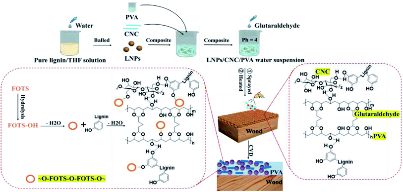 | ||
| Fig. 1 Schematic of the fabrication process for LNPs based superhydrophobic surface and possible chemical reactions during preparation. | ||
Wettability
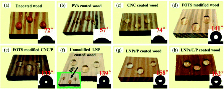
As shown in Fig. 2a–c, the pure wood, PVA coated wood, and CNC coated wood before modification were hydrophilic due to the presence of abundant hydroxyl groups on their surfaces. The pure wood and C/P coated wood after modification by FOTS showed WCAs of only 141° and 133° (Fig. 2d–e), respectively, proving that the surface rough structure of the pure wood and C/P coated wood could not meet the requirements of superhydrophobicity. So LNPs were used to construct surface rough structures on the wood surface (Fig. 2f). While the unmodified LNPs coated wood showed a WCA of 139° at the beginning, and the WCA would decrease rapidly and became hydrophilic after 30 s due to the poor hydrophobic stability of the unmodified LNPs. As shown in Fig. 2g–h, the WCAs of the LNPs/P coated wood and LNPs/C/P coated wood were up to 158° and 162° and the slide angles down to 6° and 5°, respectively, reaching superhydrophobic. Even after ∼30 min, both LNPs/P coated wood and LNPs/C/P coated wood had no significant change in WCAs, showing excellent water resistance. This was because FOTS could provide stable low surface free energy. There was no distinct difference in WCAs between the LNPs/P and LNPs/C/P ones and mainly an obvious distinction in wear resistance, which would be described in detail in the section “Mechanical strength test” below.Surface morphology
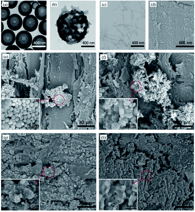
The diameter of LNPs could be controlled by changing the initial concentration of the enzymatic hydrolysis lignin in THF and the adding rate of the deionized water.32 When the initial concentration of the solution was 0.5 mg mL−1 and the adding rate was 20 mL min−1, the average diameter of LNPs was 337.8 nm. The result was consistent to its TEM image (Fig. 3a). After modification (Fig. 3b), the FOTS was fixed to the LNPs surfaces by a dehydration condensation reaction or direct attaching and LNPs became irregular, which built a micro/nano layered structure. The CNC was a material with rod structure (Fig. 3c) and the pure wood showed an uneven surface formed by destruction of the wood ducts during processing (Fig. 3d). As shown in Fig. 3e–f, the unmodified and modified LNPs coatings were not homogeneous because they would be easy to fall off due to lack of adhesion with woods, proving an adhesive was necessary to fix LNPs to wood surface. So PVA was used as the adhesive, the LNPs/P and LNPs/C/P coatings could be uniformly fixed onto the wood surfaces by one-step spray (Fig. 3g–h). In the LNPs/C/P coating, CNCs were not directly observed because the most of them were embedded in the PVA membrane due to their good compatibility with PVA. This was beneficial to the improvement of mechanical properties.Chemical composition analysis
The FTIR spectra of the unmodified LNPs, CNC and PVA is shown in the Fig. 4a. The absorption peak at 3445 cm−1 was caused by the stretching vibration of –OH in the LNP, CNC and PVA, these hydroxyls were the basis for hydrophobic modification. Of all, the peak intensity of LNPs was weaker than that of both CNC and PVA because there are fewer hydroxyl groups in LNPs. In the unmodified LNPs, the absorption peaks at 1602 cm−1 and 1512 cm−1 were caused by the vibration and tensile vibration of benzene ring skeleton, respectively, and they were the characteristic peaks of lignin;36 the tensile vibration and plane deformation stretching vibration of C–H bond of benzene ring skeleton contributed to the absorption peaks at 1462 cm−1 and 1427 cm−1, respectively.31 In the unmodified CNC, the peak at 1060 cm−1 was caused due to the vibrations of C–C, C–OH, and C–H ring and side group; the plane bending of C–H results in the peak at 1375 cm−1 and the peaks at 1433 cm−1 and 1646 cm−1 were resulted from the plane bending vibrations of HCH and OCH and the bending of OH in absorbed water, respectively. In the unmodified PVA, the characteristic peak of carbon chain caused by the stretching vibration of C–C appears at 850 cm−1 and the stretching vibration of C–O led to the peak at 1096 cm−1. As shown in Fig. 4b, in the unmodified LNPs/C/P coating, the peaks caused by the vibration and tensile vibration of the benzene ring skeleton of LNPs could be found at 1602 cm−1 and 1512 cm−1. The plane bending of C–H in CNC was located at 1375 cm−1, the vibrations of C–C, C–OH, and C–H ring and side group in CNC was found at 1060 cm−1 and the peak caused by stretching vibration of C–C in PVA was found at 850 cm−1. At this time, no new absorption peaks were found as opposed to the FTIR spectra of individual LNPs, CNC and PVA, proving that there was no chemical bond among the three, which is consistent to the above forming mechanism analysis. After modification with FOTS, in addition to the presence of the above characteristic peaks, the FOTS modified LNPs/C/P coating showed two new absorption peaks at 1239 cm−1 and 1143 cm−1, which were caused by the stretching vibration of C–F, suggesting that FOTS was successfully attached to the surface of the LNPs/C/P coating.16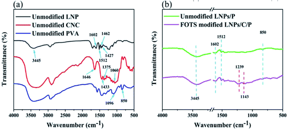 | ||
| Fig. 4 FTIR spectra of (a) the unmodified LNP, CNC and PVA and (b) the unmodified LNPs/C/P and LNPs/C/P after modification. | ||
To further determine whether FOTS was successfully attached to the surface of the composite coatings, the elements on the composite coatings before and after modification were analyzed by XPS. As shown in the Fig. 5a, the LNPs/C/P coating before modification showed the characteristic peaks of only both C (284 eV) and O (533 eV) elements, respectively. Because there are only both C, H and O elements in all three compositions and H element cannot be not detected by XPS. The modified LNPs/C/P coating shows the new characteristic peaks from F and Si elements which were found at 687 eV and 99 eV, respectively, suggesting that there was FOTS existing. As shown in Table 1, before modification, there were only C, O and H elements in the LNPs/C/P coating and the C/O ratio was 3.71. After modification by FOTS, both Si and F elements were present in the surface of the modified LNPs/C/P and the C/O ratio is up to 4.01 due to the higher content of C in the FOTS after hydrolysis than that of O. This also indirectly suggested the existence of FOTS. Peaks analysis was performed on C1s of the unmodified LNPs/C/P coating (Fig. 5b). The peak areas of C–C, C–H, C–O–C, C–OH, and O–C–O bonds could be seen because lignin is mainly composited of three phenylpropane units. In addition, the F–C–F, F–C(–F)–F peaks (Fig. 5c) and Si–O bond (Fig. 5d) formed by the dehydration condensation reaction between FOTS and water in air (or FOTS-OH and hydroxyl groups on the coating surface) could also be found, indicating that FOTS were successfully attached to the surface of the LNPs/C/P coating.
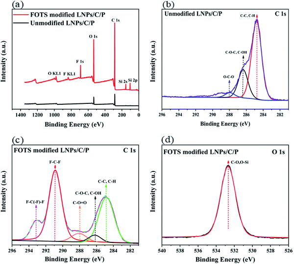 | ||
| Fig. 5 XPS spectra of (a) the LNPs/C/P before and after modification, (b) C1s of unmodified LNPs/C/P, (c) O1s and (d) C1s of FOTS modified LNPs/C/P. | ||
| Atomic | Atomic percent (%) | |
|---|---|---|
| Unmodified LNPs/C/P | Modified LNPs/C/P | |
| C | 78.79 | 73.01 |
| O | 21.21 | 18.09 |
| F | — | 8.84 |
| Si | — | 0.06 |
| C/O | 3.71 | 4.04 |
Thermal stability analysis
Thermal stability is an important indicator for superhydrophobic surfaces. The decomposition process usually is composed of three stages including dehydration, rapid decomposition, and slow carbonization. As shown in Fig. 6a, the weight loss before 100 °C was mainly caused by the evaporation of the water absorbed by the materials due to their hydrophilia. In the unmodified CNC, the mass decreased slightly with the removal of C2 hydroxyl groups in the temperature range of 100–224 °C; during 224–405 °C, the fast weight loss was caused by the removal of the C4 alcohol hydroxyl group; during 405–480 °C, due to the slow decomposition and carbonization of the remaining residue, the final mass residual of CNC was about 35%. In the unmodified LNPs, there was a high decomposition temperature of about 280 °C, showing good thermal stability; during 280–451 °C, the devolatilization stage of organic matter such as the decomposition of methoxy (–OCH3), methyl (–CH3) and methylene (–CH2) and the decarboxylation or decomposition of carbonyl (–C![[double bond, length as m-dash]](https://www.rsc.org/images/entities/char_e001.gif) O) led to the mass loss; after the carbonization stage (451–800 °C), the final mass residual of LNPs reached 43% due to its high carbon content.37,38 In the unmodified PVA, during 237–350 °C, the hydroxy group was dehydrated and forms volatile organic compounds and conjugated unsaturated polyene, leading to rapid mass decline; during 350–450 °C, polyene residue was degraded into alkanes and aromatics by intramolecular cyclization, resulting in continuous degradation of PVA mass; after 450 °C, the PVA mass gradually tend to be stable and the final residual mass was about 25%.39 According to the DTG (Fig. 6c), the fastest degradation rate of all three LNPs, CNC and PVA occurred at 363 °C, 243 °C and 265 °C, respectively. After mixing LNPs, CNC and PVA, the decomposition temperature of the LNPs/C/P was up to 293 °C and higher than that of the single component (Fig. 6b). This might be because the hydrogen bonding among the three components improved the thermal stability. After the LNPs/C/P coating was modified by FOTS, large numbers of hydroxyl groups were replaced by the fluorosilane chains, which had much better thermal stability than the hydroxyl groups. Therefore, pyrolysis did not take place until 329 °C, and the carbonization stage occurred after 441 °C. Compared with the unmodified one, the thermal stability of the modified LNPs/C/P coating was significantly enhanced. Due to LNPs as the main component, the fastest decomposition rate of the LNP/C/P coatings before and after modification occurred at 360 °C and 370 °C, respectively, close to that of LNPs (Fig. 6d).
O) led to the mass loss; after the carbonization stage (451–800 °C), the final mass residual of LNPs reached 43% due to its high carbon content.37,38 In the unmodified PVA, during 237–350 °C, the hydroxy group was dehydrated and forms volatile organic compounds and conjugated unsaturated polyene, leading to rapid mass decline; during 350–450 °C, polyene residue was degraded into alkanes and aromatics by intramolecular cyclization, resulting in continuous degradation of PVA mass; after 450 °C, the PVA mass gradually tend to be stable and the final residual mass was about 25%.39 According to the DTG (Fig. 6c), the fastest degradation rate of all three LNPs, CNC and PVA occurred at 363 °C, 243 °C and 265 °C, respectively. After mixing LNPs, CNC and PVA, the decomposition temperature of the LNPs/C/P was up to 293 °C and higher than that of the single component (Fig. 6b). This might be because the hydrogen bonding among the three components improved the thermal stability. After the LNPs/C/P coating was modified by FOTS, large numbers of hydroxyl groups were replaced by the fluorosilane chains, which had much better thermal stability than the hydroxyl groups. Therefore, pyrolysis did not take place until 329 °C, and the carbonization stage occurred after 441 °C. Compared with the unmodified one, the thermal stability of the modified LNPs/C/P coating was significantly enhanced. Due to LNPs as the main component, the fastest decomposition rate of the LNP/C/P coatings before and after modification occurred at 360 °C and 370 °C, respectively, close to that of LNPs (Fig. 6d).
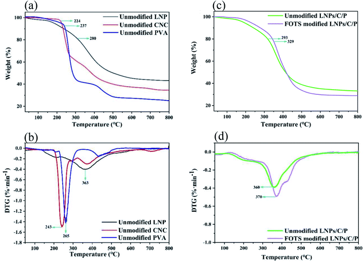 | ||
| Fig. 6 (a) TG and (b) DTG curves of the unmodified LNPs, CNC and PVA; (c) TG and (d) DTG curves of the LNPs/C/P before and after modification. | ||
Mechanical strength test
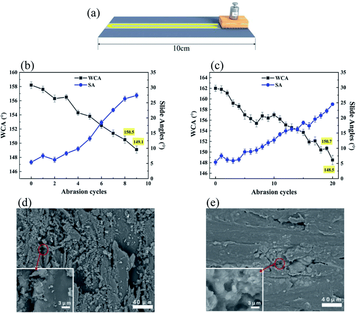
The mechanical strength of superhydrophobic surfaces could be evaluated by a sandpaper abrasion test, where the coated wood was placed on the sandpaper (800-grit) and moved for 10 cm along the sandpaper under a loading of 50 g, followed by going back in the same way (Fig. 7a). Such is considered as one abrasion cycle. As shown in Fig. 7b, before the WCA is lower than 150°, the modified LNPs/P coating without CNC could withstand eight abrasion cycles, showing a good stability. This was because PVA could provide good adhesion. During abrasion, the WCAs gradually dropped and the slide angles steadily went up, resulting from the constant destroy of the surface rough structure (Fig. 7d) and the increase of the actual contact area between the water droplets and coating surface.The FOTS attached to the coating would be also removed when the coating was scratched off from the wood surface. At the same time, a larger exposure of the unmodified wood surface also led to a reduction in the superhydrophobic properties. The number of abrasion cycles went up to nineteen after addition of CNC, proving the LNPs/C/P coating had better abrasion resistance than the LNPs/P one (Fig. 7c). This is mainly because CNC is of high crystal structure and has good compatibility with PVA and in the composite system, being able to form large numbers of hydrogen bonds with surrounding PVA chains and LNPs (as shown in Fig. 1) and further enhance the mechanical strength of the coating. As the increase of the abrasion cycles, the surface rough structure of the LNPs/P and LNPs/C/P coatings was seriously destroyed and the most of the LNPs were worn off, only some LNPs left in the pit of the wood surface (Fig. 7e), resulting in the loss of superhydrophobicity.
UV resistance test
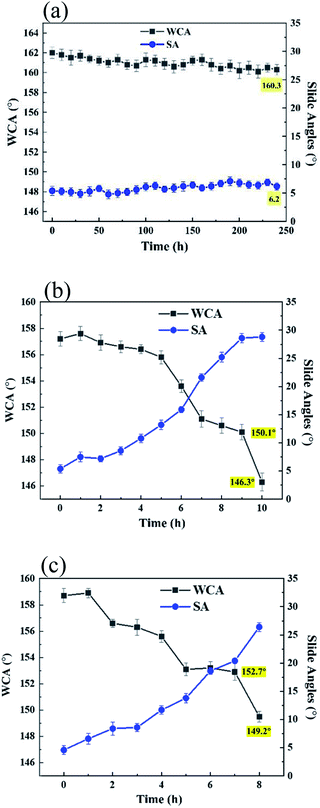
As we know, lots of materials would tend to age when exposed to the sun light, which is mainly caused by the role of UV rays of sun light. To detect the aging resistance of the coatings, two kinds of UV light (one is power of 15 W and wavelength of 254 nm and the other one is power of 1000 W, wavelength of 365 nm) were used to test UV resistance of the coatings and the radiation distance is 20 cm. When the coatings were exposed to the UV light with the power of 15 W and the WCAs were measured each 12 h, the WCAs of LNPs/C/P coatings have no significant reduction after 240 h (Fig. 8a), which was comparable to that (∼175 h) of the silica/epoxy resin superhydrophobic surface in this report40 where there were similar test conditions, showing excellent UV resistance. To imitate some occasions with super intense UV light, the one with power of 1000 W and wavelength of 365 nm was selected and the WCAs and slide angles were measured each 1 h. As shown in Fig. 8a and b, both the LNPs/P and LNPs/C/P coatings could still retain superhydrophobic for 7 h, showing a strong UV resistance. This was because lignin as the main material contains large numbers of benzene rings, carbonyl, double bonds, and other conjugated structures, which are good for absorption of UV light.30 Both the LNPs/P and LNPs/C/P coatings showed similar results, indicating that CNC mainly affected the strength of coating and had no effect on UV resistance. However, with increase of UV radiation time, the WCAs kept falling and the slide angles kept rising. This might be because the used UV light was too strong, leading to the cracking of the adhesive and the loss of superhydrophobicity. However, it would be a long enough time if used in the ordinary sunlight.Conclusions
Lignin is an environmentally friendly biomass material. LNPs prepared by self-assembly of lignin molecule were used to build surface rough structures for superhydrophobic surfaces, thus extending application of lignin. The preparation process of the LNPs/C/P superhydrophobic surface was simple. And in addition to excellent superhydrophobic properties, the resulting surface showed good sandpaper abrasion resistance due to the high strength of CNC and good compatibility between CNC and PVA, as well as long UV resistance due to large numbers of benzene rings, carbonyl, double bonds, and other conjugated structures in lignin, which are beneficial to UV absorption. The LNPs/C/P superhydrophobic surface has a great potential application in the production and preparation of outdoor superhydrophobic materials due to its advantages of low cost, renewability and good UV resistance.Conflicts of interest
There are no conflicts to declare.Acknowledgements
This work was supported by the National Natural Science Foundation of China (No. 31901246), Natural Science Foundation of Zhejiang Province (No. LY21C160002), Scientific Research Development Foundation of Zhejiang A&F University (No. 2021KX0042).References
- W. Yang, H. Ding and G. Qi, et al., Biomacromolecules, 2021, 22, 2693–2701 CrossRef CAS PubMed.
- M. G. Saborio, K. Privat and B. N. Tran, et al., ACS Appl. Nano Mater., 2022, 5, 3686–3700 CrossRef CAS.
- J. Jeon, J. k. Yoo and S. Yim, et al., ACS Sustain. Chem. Eng., 2019, 7, 17580–17586 CrossRef CAS.
- L. Eneko, M. Imízcoz and J. X. Toh, et al., ACS Sustain. Chem. Eng., 2018, 6, 9037–9046 CrossRef PubMed.
- K. A. Mahmoud and M. Zourob, Analyst, 2013, 138, 2712–2719 RSC.
- S. S. Latthe, R. S. Sutar and V. S. Kodag, et al., Prog. Org. Coat., 2019, 128, 52–58 CrossRef CAS.
- J. Sheng, Y. Xu and J. Yu, et al., ACS Appl. Mater. Interfaces, 2017, 9, 15139–15147 CrossRef CAS PubMed.
- X. Yin, S. Yu and K. Wang, et al., Chem. Eng. J., 2020, 394, 124925 CrossRef CAS.
- Y. Lai, Y. Tang and J. Gong, et al., J. Mater. Chem., 2012, 22, 7420–7426 RSC.
- B. Han, H. Wang and S. Yuan, et al., Prog. Org. Coat., 2020, 149, 105922 CrossRef CAS.
- J. Huang, S. Wang and S. Lyu, et al., Ind. Crop. Prod., 2018, 122, 438–447 CrossRef CAS.
- X. Zheng and S. Fu, Colloid. Surface., 2019, 560, 171–179 CrossRef CAS.
- P. Peng, Q. Ke and G. Zhou, et al., J. Colloid Interface Sci., 2013, 395, 326–328 CrossRef CAS PubMed.
- W. Xu, P. Yi and J. Gao, et al., ACS Appl. Mater. Interfaces, 2020, 12, 3042–3050 CrossRef CAS PubMed.
- P. Nguyen-Tri, F. Altiparmak and N. Nguyen, et al., ACS Omega, 2019, 4, 7829–7837 CrossRef CAS PubMed.
- X. Wang, B. Ding and J. Yu, et al., Nano Today, 2011, 6, 510–530 CrossRef CAS.
- C. Zhang, S. Zhang and P. Gao, et al., Thin Solid Films, 2014, 570, 27–32 CrossRef CAS.
- J. Huang, S. Lyu and F. Fu, et al., RSC Adv., 2016, 6, 106194–106200 RSC.
- Z. Wu, H. Wang and X. Tian, et al., Polymer, 2014, 55, 187–194 CrossRef CAS.
- X. Chen, Y. Gong and D. Li, et al., Colloid. Surface., 2016, 492, 19–25 CrossRef CAS.
- C. Ma, Y. Li and J. Zhang, et al., J. Coat. Technol. Res., 2021, 18, 415–433 CrossRef CAS.
- M. I. Rahmah, R. S. Sabry and W. J. Aziz, Int. J. Min. Met. Mater., 2021, 28, 1075 Search PubMed.
- H. Liu, X. Li and L. Lv, et al., Mater. Res. Express, 2020, 7, 116403 CrossRef CAS.
- S. Abad, N. N. Ilkhechi and M. Adel, et al., Appl. Surf. Sci., 2020, 147495 CrossRef.
- L. Wu, L. Li and B. Li, et al., ACS Appl. Mater. Interfaces, 2015, 7, 4936–4946 CrossRef CAS PubMed.
- D. Li, H. Wang and Y. Liu, et al., Chem. Eng. J., 2019, 367, 169–179 CrossRef CAS.
- A. B. Gurav, Q. Guo and Y. Tao, et al., Mater. Lett., 2016, 182, 106–109 CrossRef CAS.
- J. Huang, S. Lyu and Z. Chen, et al., J. Colloid Interface Sci., 2019, 536, 349–362 CrossRef CAS PubMed.
- Y. Zhang, Y. Zhang and Q. Cao, et al., Sci. Total Environ., 2020, 706, 135807 CrossRef CAS PubMed.
- X. Gong, Y. Meng and J. Zhu, et al., Ind. Crop. Prod., 2021, 166, 113471 CrossRef CAS.
- W. Yang, M. Rallini and D. Wang, et al., Compos. Appl. Sci. Manuf., 2018, 107, 61–69 CrossRef CAS.
- F. Xiong, Y. Han and S. Wang, et al., ACS Sustain. Chem. Eng. J., 2017, 5, 2273–2281 CrossRef CAS.
- F. Xiong, Y. Han and S. Wang, et al., Ind. Crop. Prod., 2017, 100, 146–152 CrossRef CAS.
- Y. Yang, Q. Liu and H. Wang, et al., Chin. J. Chem. Eng., 2017, 25, 1395–1401 CrossRef CAS.
- F. Su and K. Yao, ACS Appl. Mater. Interfaces, 2014, 6, 8762–8770 CrossRef CAS PubMed.
- A. Casas, M. V. Alonso and M. Oliet, et al., J. Chem. Technol. Biot., 2012, 87, 472–480 CrossRef CAS.
- X. Lu, X. Zhu and H. Guo, et al., Biomass Convers. Biorefin., 2020, 1–10 Search PubMed.
- X. Zhu, Y. Dong and X. Lu, et al., Cell. Chem. Technol., 2019, 53, 53–61 CrossRef CAS.
- A. A. Rowe, M. Tajvidi and D. J. Gardner, J. Therm. Anal. Calorim., 2016, 126, 1371–1386 CrossRef CAS.
- D. Zhi, Y. Lu and S. Sathasivam, et al., J. Mater. Chem. A, 2017, 5, 10622–10631 RSC.
Footnote |
| † The authors contributed equally to the article. |
| This journal is © The Royal Society of Chemistry 2022 |

